

Page 1
SPECIFICATIONS
DIMENSION
Width 13 inches (330 mm)
Depth 26 inches (660 mm)
Height (without legs) 20 3/4 inches (520 mm)
WEIGHT
Shipping 140 pounds (63.6 kg)
Empty 125 pounds (56.8 kg)
Operating 163 pounds (74.1 kg)
WATER REQUIREMENTS
CAUTION
IF WATER SOURCE EXCEEDS 50 PSIG (3.52 KG/CM2), A WATER
REGULATOR ASSEMBLY MUST BE USED TO LIMIT WATER
PRESSURE TO 50 PSIG (3.52 KG/CM2). FAILURE TO USE A WATER
REGULATOR WILL RESULT IN IMPROPER PERFORMANCE OF
DISPENSER.
Minimum flowing pressure of zero (0) PSIG (0 kg/cm
2
, 0 BAR)
Maximum static pressure of 50 PSIG (3.52 kg/cm
2
, 3.45 BAR)
CARBON DIOXIDE (CO
2) REQUIREMENTS
Minimum pressure of 70 PSIG (4.92 kg/cm
2
, 4.83 BAR)
Maximum pressure of 80 PSIG (5.62 kg/cm2, 5.52 BAR)
ICE BANK WEIGHT
11 to 13 pounds (5.0 to 5.9 kg)
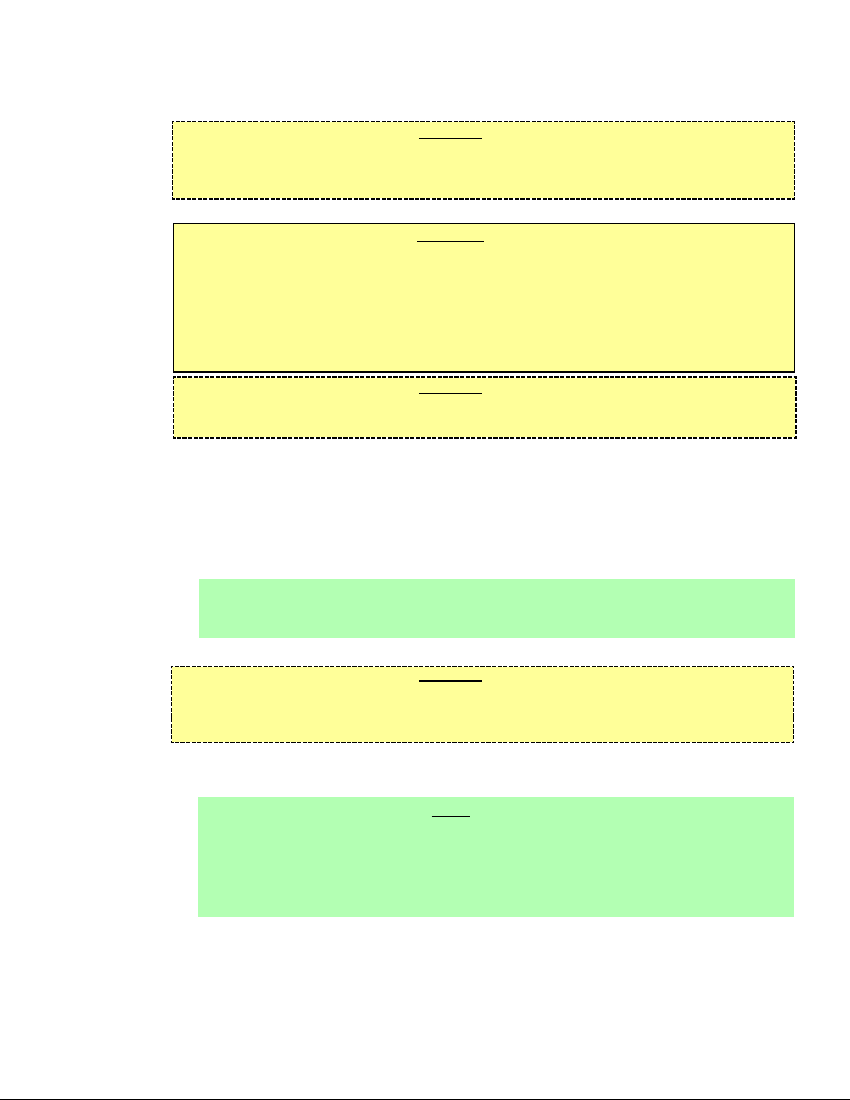
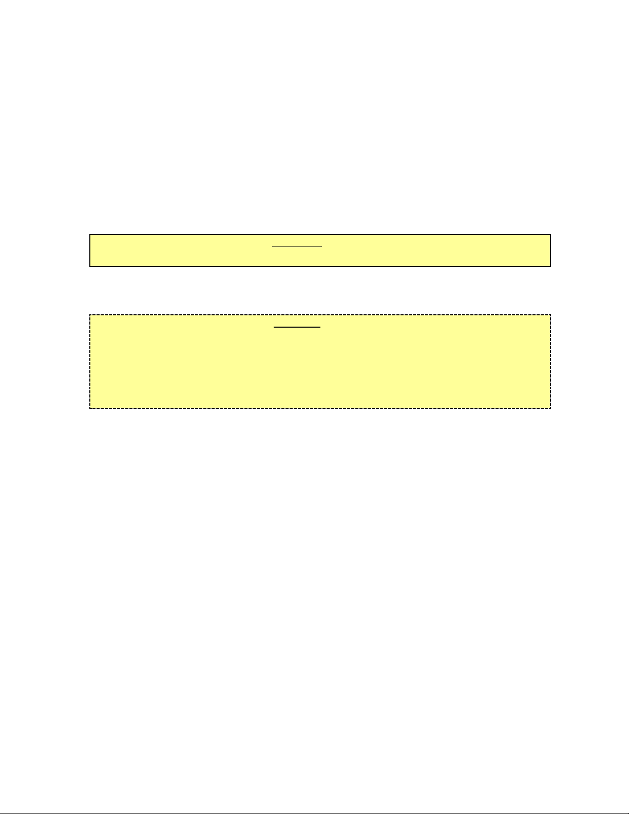
INSTALLATION AND SERVICE MANUAL
LANCER SERIES 600, LFCV
COLD CARBONATED DISPENSER
This manual is an initial issue
DATE: 03/29/02
P.N. 28–0517
• FAX ENGINEERING: • 210-310-7096 •
• "Lancer" is the registered trademark of Lancer •
• Copyright — 2002 by Lancer, all rights reserved. •
Please refer to the Lancer web site (www.lancercorp.com) for
information relating to Lancer Installation and Service Manuals,
Instruction Sheets, Technical Bulletins, Service Bulletins, etc.
6655 LANCER BLVD. • SAN ANTONIO, TEXAS 78219 USA • (210) 310-7000
FAX SALES
• NORTH AMERICA – 210-310-7245 • INTERNATIONAL SALES – 210-310-7242 • CUSTOMER SERVICE – 210-310-7242 •
• LATIN AMERICA – 210-310-7245 • EUROPE – 32-2-755-2399 • PACIFIC – 61-8-8268-1978 •
Page 2

TABLE OF CONTENTS
SPECIFICATIONS......................................................................................................................................Cover
DISPENSER INSTALLATION HIGHLIGHTS......................................................................................................i
TABLE OF CONTENTS ......................................................................................................................................i
1. INSTALLATION ...........................................................................................................................................1
1.1 RECEIVING .......................................................................................................................................1
1.2 UNPACKING ......................................................................................................................................1
1.3 UNPACKING INSTALLATION KITS ...................................................................................................1
1.4 SELECTING A COUNTER LOCATION .............................................................................................1
1.5 MOUNTING THE DISPENSER..........................................................................................................1
1.6 CONNECTING THE DRAIN...............................................................................................................1
1.7 FILLING UNIT WITH WATER ............................................................................................................1
1.8 CONNECTING TO ELECTRICAL POWER .......................................................................................2
1.9 CONNECTING TO WATER SUPPLY.................................................................................................2
1.10 CONNECTING THE CO2 SUPPLY....................................................................................................3
1.11 CONNECTING TO BAG-IN-BOX (BIB) SYRUP SUPPLY (UNITS WITH
BUILT-IN SYRUP PUMPS) ................................................................................................................3
1.12 CONNECTING TO REMOTE BIB SYRUP PUMPS...........................................................................3
1.13 REMOTE PRESSURIZED SYRUP SUPPLY.....................................................................................3
1.14 PURGING THE CARBONATION SYSTEM .......................................................................................4
2. SCHEDULED MAINTENANCE ...................................................................................................................4
2.1 DAILY .................................................................................................................................................4
2.2 WEEKLY.............................................................................................................................................4
2.3 MONTHLY ..........................................................................................................................................4
2.4 EVERY SIX (6) MONTHS ..................................................................................................................4
2.5 YEARLY..............................................................................................................................................4
i
DISPENSER INSTALLATION HIGHLIGHTS
Listed below are eight (8) critical elements which will aid in a successful installation.
1. Fill water bath until water over flows from tank overflow tube.
2. The carbonator pump motor must be disconnected from the power supply (refer to Section 1.8A) prior to
connection to water supply for initial build up of ice bank. Failure to do so will result in automatic shut off of
carbonator (see Item 6 below) or damage to the pump.
3. If this dispenser is installed in an area that is susceptible to ±10% variation of the nominal line voltage,
consider installing a surge protector or similar protection device.
4. There is a five (5) minute delay which prevents the compressor and condenser fan from starting until the delay
has lapsed. If electrical current is interrupted, there is always a five (5) minute delay before the compressor starts.
5. The unit is equipped with a protective timer for the carbonator pump motor, set for three (3) minutes. If the
carbonator motor has timed out, it must be manually reset by either momentarily unplugging the unit or switching
off the ON/OFF switch. Once power is restored, the five (5) minute compressor delay would be in effect.
6. Supply Water Pressure: Minimum – Zero (0) Flowing PSIG (0 kg/cm
2
)
[25 PSIG (1.76 kg/cm
2
)
Flowing in quiet
mode]; Maximum static– 50 PSIG (3.5 kg/cm2). If pressure is over 50 PSIG, a water pressure regulator must be
used.
7. CO
2 Pressure: Recommend nominal pressure 75 PSIG (5.27 kg/cm
2
, 5.17 BAR). Pressure may be reduced to a
minimum of 70 PSIG (4.92 kg/cm
2
, 4.83 BAR) if double acting syrup pumps are being used. It may be increased
to a maximum of 80 PSIG (5.62 kg/cm
2
, 5.52 BAR) only when internal syrup pumps are being used with highly
viscous syrups. Important: Internal syrup pumps may not work at pressures less than 70 PSIG. CO
2 pressure over 80 PSIG
may result in damage or leakage from the syrup pump system or may cause excessive foam in the drink.
8. Valve Adjustment: Make sure drink temperature is below 40°F (4.4°C) before checking or adjusting brix.
Page 3

3. DISPENSER CLEANING AND SANITIZING ..............................................................................................4
3.1 AMBIENT PROCESS.........................................................................................................................4
4. CONNECTION FOR PLAIN WATER PRODUCT........................................................................................6
4.1 PROCEDURE.....................................................................................................................................6
5. SETTING MEMBRANE SWITCH AND PLUMBING CONFIGURATIONS .................................................6
5.1 GENERAL ..........................................................................................................................................6
5.2 CARB/PLAIN WATER CONFIGURATION .........................................................................................7
5.3 PORTION CONTROL FEATURE .......................................................................................................7
6. LANCER FLOW CONTROL MODULE (LFCV) ADJUSTMENT AND MAINTENANCE............................7
6.1 GENERAL ..........................................................................................................................................7
6.2 ADJUSTING WATER FLOW..............................................................................................................8
6.3 ADJUSTING SYRUP FLOW ..............................................................................................................8
6.4 CLEANING AND SANITIZING PROCEDURES.................................................................................8
6.5 DAILY NOZZLE/DIFFUSER CLEANING............................................................................................8
6.6 MONTHLY NOZZLE/DIFFUSER SANITIZING...................................................................................9
6.7 VALVE (SYRUP MODULE OR SODA MODULE) ..............................................................................9
6.8 NOZZLE HOUSING .........................................................................................................................10
6.9 NOZZLE BODY AND FITTINGS ......................................................................................................10
7. WATER PUMP ...........................................................................................................................................11
8. TROUBLESHOOTING...............................................................................................................................12
8.1 MISCELLANEOUS LEAKAGE .........................................................................................................12
8.2 INSUFFICIENT WATER FLOW........................................................................................................12
8.3 INSUFFICIENT SYRUP FLOW........................................................................................................21
8.4 NO PRODUCT DISPENSED ...........................................................................................................12
8.5 WATER ONLY DISPENSED; NO SYRUP; OR SYRUP ONLY DISPENSED; NO WATER.............12
8.6 VALVE WILL NOT SHUT OFF .........................................................................................................12
8.7 SYRUP ONLY DISPENSED. NO WATER, BUT CO2 GAS DISPENSED WITH SYRUP ..............13
8.8 DISPENSER DOES NOT DISPENSE PROPER SYRUP AND/OR
WATER FROM PROPER NOZZLE..................................................................................................13
8.9 EXCESSIVE FOAMING ...................................................................................................................13
8.10 WATER CONTINUALLY OVERFLOWS FROM WATER BATH INTO DRIP TRAY .........................13
8.11 COMPRESSOR STARTS AND CONTINUES TO RUN UNTIL FREEZE UP AND
WILL NOT CUT OFF........................................................................................................................13
8.12 WARM DRINKS................................................................................................................................13
8.13 COMPRESSOR DOES NOT START (NO HUM), CONDENSER FAN MOTOR DOES
NOT RUN AND NO ICE BANK ........................................................................................................14
8.14 COMPRESSOR DOES NOT START (NO HUM), BUT CONDENSER FAN MOTOR RUNS..........14
8.15 COMPRESSOR DOES NOT START BUT HUMS ...........................................................................14
8.16 COMPRESSOR STARTS BUT DOES NOT SWITCH OFF START WINDING ...............................14
8.17 COMPRESSOR STARTS AND RUNS A SHORT TIME BUT SHUTS OFF ON OVERLOAD .........14
8.18 COMPRESSOR RUNS NORMALLY, BUT WATER LINE IS FROZEN............................................15
8.19 COMPRESSOR CYCLES ON AND OFF FREQUENTLY DURING THE
INITIAL PULLDOWN AND/OR NORMAL OPERATIONS ................................................................15
8.20 PLAIN WATER FLOW IS INSUFFICIENT........................................................................................15
8.21 SUSPECT FAULTY PCB..................................................................................................................15
8.22 CIRCUIT BREAKER TRIPPING.......................................................................................................15
8.23 BIB PUMP DOES NOT OPERATE WHEN DISPENSING VALVE IS OPENED..............................15
8.24 BIB PUMP OPERATES BUT NO FLOW..........................................................................................15
8.25 BIB PUMP CONTINUES TO OPERATE WHEN BAG IS EMPTY ...................................................15
8.26 BIB PUMP FAILS TO RESTART AFTER BAG REPLACEMENT ....................................................16
8.27 BIB PUMP FAILS TO STOP WHEN DISPENSING VALVE IS CLOSED.........................................16
8.28 LOW OR NO CARBONATION .........................................................................................................16
8.29 CARBONATOR PUMP NOT RUNNING ..........................................................................................16
9. ILLUSTRATIONS, PARTS LISTINGS, AND WIRING DIAGRAMS ..........................................................17
9.1 COMPRESSOR DECK ASSEMBLY ...........................................................................................17-18
9.2 MINIPUMP ASSEMBLY (FIVE FLAVOR, PN 82-3095; FOUR FLAVOR, PN 82-3095-04) ........19-20
9.3 SERIES 600 LFCV CABINET ASSEMBLY.................................................................................21-22
9.4 CARBONATOR PUMP BRACKET ASSEMBLY...............................................................................23
9.5 CONTROL HOUSING (PN 52-2593) ...............................................................................................24
9.6 SERIES 600 LFCV CARBONATOR, WATER/SYRUP LINES ASSEMBLIES ............................25-26
9.7 WIRING DIAGRAM, 600 LFCV, PN 06-2451...................................................................................27
ii
TABLE OF CONTENTS (CONTINUED)
Page 4

1
1. INSTALLATION
1.1 RECEIVING
Each unit is tested and thoroughly inspected before shipment. At the time of shipment, the carrier
accepts the unit and any claim for damages must be made with the carrier. Upon receiving units
from the delivering carrier, carefully inspect carton for visible indication of damage. If damage
exists, have carrier note same on bill of lading and file a claim with the carrier.
1.2 UNPACKING
A. Cut banding and remove.
B. Remove top portion of carton by lifting up.
C. Remove accessory kit and loose parts from top packaging.
D. Remove side inserts.
E. Lift unit up by plywood shipping base and remove lower portion of carton.
F. Inspect unit for concealed damage and if evident notify delivering carrier and file a claim against
same.
G. Remove plywood shipping base from unit by moving unit so that one side is off the counter top
or table allowing access to screws on the bottom of the plywood shipping base.
NOTE
If unit is to be transported, it is advisable to leave the unit secured to the plywood base.
H. If unit is to be installed with optional feet, assemble feet to unit by tilting unit. DO NOT LAY UNIT
ON ITS SIDE OR BACK.
1.3 UNPACKING INSTALLATION KITS
A. Inspect kits for concealed damage and if evident, notify delivering carrier and file a claim against
same.
B. Each kit contains a list of the parts and a drawing showing the proper assembly of the parts.
1.4 SELECTING A COUNTER LOCATION
A. Select a location close to a properly grounded electrical outlet and water supply that meet the
requirements as scheduled on the specification page.
CAUTION
FAILURE TO MAINTAIN SPECIFIED CLEARANCE WILL CAUSE THE COMPRESSOR TO
OVERHEAT AND WILL RESULT IN PREMATURE COMPRESSOR FAILURE.
B. Condenser air is drawn in the top of the unit and discharged out the top of the unit. A minimum
of eight (8) inches (203 mm) clearance must be maintained over the top of the unit.
1.5 MOUNTING THE DISPENSER
A. The dispenser is designed to be permanently mounted and sealed to the counter.
NOTE
NSF listed units must be sealed to the counter using FDA approved Silicone or be elevated
above the counter in accordance with NSF directives.
B. When the dispenser is to be permanently bolted to the counter top, seal dispenser base to
counter top with a bead of clear, FDA approved, silicone caulk or sealant which provides a
smooth and easily cleaned bond to the counter.
1.6 CONNECTING THE DRAIN
A. Remove cup rest. Lift splash plate up and pull out and down on the bottom to remove.
B. Remove the drip tray from the unit and connect the drain tube to the drain fitting located on the
back.
C. Route the drain tube to a suitable drain.
D. Reinstall the drip tray, splash plate, and cup rest.
1.7 FILLING UNIT WITH WATER
A. Remove the top cover from the unit.
Page 5
2
B. Locate the fill tube. It is located next to the carbonator relief valve.
C. Using a funnel or tube, fill the water bath compartment with water until it flows out of the
overflow tube into the drip tray.
CAUTION
THE WATER BATH COMPARTMENT MUST BE FILLED WITH WATER BEFORE PLUGGING IN
THE UNIT. OTHERWISE, THE COMPRESSOR DECK AND CONDENSER FAN WILL NOT
OPERATE.
1.8 CONNECTING TO ELECTRICAL POWER
WARNING
THIS UNIT MUST BE PROPERLY ELECTRICALLY GROUNDED TO AVOID POSSIBLE FATAL
ELECTRICAL SHOCK OR SERIOUS INJURY TO THE OPERATOR. THE POWER CORD IS
PROVIDED WITH A THREE PRONG GROUNDED PLUG. IF A THREE-HOLE GROUNDED
ELECTRICAL OUTLET IS NOT AVAILABLE, USE AN APPROVED METHOD TO GROUND THE
UNIT.
DO NOT USE EXTENSION CORDS WITH THIS UNIT. DO NOT “GANG” TOGETHER WITH
OTHER ELECTRICAL DEVICES ON THE SAME OUTLET.
CAUTION
FAILURE TO DISCONNECT THE MOTOR POWER SUPPLY WILL DAMAGE THE CARBONATOR
MOTOR AND PUMP AND VOID THE WARRANTY.
A. Disconnect the power supply to the carbonator motor by disconnecting the three pin connector
located near the top left corner of the control board located under the valve shroud.
B. Check the dispenser serial number plate for unit’s correct electrical requirements. Do not plug
into wall electrical outlet unless serial number plate voltage shown agrees with local current
available.
C. Route the power supply cord to a grounded electrical outlet of the proper voltage and amperage
rating, and plug in the unit. This will turn on the refrigeration system and allow it to start cooling
while completing the rest of the installation.
NOTE
The agitator motor will start immediately, but the compressor and fan motor will not start until the
five (5) minute delay has elapsed.
1.9 CONNECTING TO WATER SUPPLY
CAUTION
IF WATER SOURCE EXCEEDS 50 PSIG (3.52 KG/CM2), A WATER REGULATOR KIT MUST BE
USED TO LIMIT WATER PRESSURE TO 50 PSIG (3.52 KG/CM2). FAILURE TO USE
REGULATOR WILL RESULT IN IMPROPER PERFORMANCE OF DISPENSER.
A. Using appropriate tubing and fittings, connect tubing assembly to water source. DO NOT
CONNECT TO DISPENSER AT THIS TIME.
B. Flush water supply line thoroughly.
NOTE
If the water source is above 50 PSIG (3.52 kg/cm2), cut tubing assembly and install a Water
Regulator.
This unit meets NSF requirements for backflow prevention for internally carbonated beverage
dispensers. It is the responsibility of the installer to ensure compliance with any additional Federal,
state or local codes.
C. Route tubing through hole in counter or through opening in rear of dispenser and through area
behind splash plate to carbonator area. Connect to water inlet fitting.
D. Leave 12 inches (304.8 mm) of extra tubing length below the counter for servicing and moving
the dispenser.
E. Turn on water supply. Check for leaks.
F. Set to 50 PSIG (3.52 kg/cm
2
) static pressure.
Page 6
3
1.10 CONNECTING THE CO
2 SUPPLY
A. Connect high pressure CO
2 regulator assembly to CO2 cylinder. Use a new CO2 tank washer
if regulator does not have built-in o-ring seal.
B. Place CO2 cylinder in service location under counter, etc., and secure it with a safety chain.
C. Using appropriate tubing and fittings, connect tubing assembly to tank mount regulator using
flare seal washer (PN 05-0011). Use a back-up wrench to prevent damage to regulator
assembly.
D. Route gas line through hole in counter or through opening in the rear of the dispenser into area
behind splash plate.
E. Leave 12 inches (304.8 mm) of extra tubing length below the counter for servicing and moving
the dispenser.
F. Remove the protective cap from the elbow on the back of the CO
2 manifold (located on top of
mini pumps on left side of unit) and connect the CO2 supply line for units with internal syrup
pumps.
W
ARNING
DO NOT TURN ON THE CO2 SUPPLY AT THIS TIME.
G. If dispenser does not have built in syrup pumps, remove cap from CO
2 barb on carbonator relief
valve and connect to tubing.
1.11 CONNECTING TO BAG-IN-BOX (BIB) SYRUP SUPPLY (Units with built-in Syrup Pumps)
CAUTION
THE SYRUP INLET TUBING SHIPPED WITH THE INSTALLATION KIT SHOULD BE CUT INTO
PIECES EIGHT (8) FEET (2.4 M) LONG. THESE LINES CAN BE EXTENDED UP TO A MAXIMUM
OF 12 FEET (3.7 M). THE MAXIMUM HEIGHT OF THE PUMPS ABOVE THE LOWEST BIB
PACKAGE SHOULD NOT EXCEED EIGHT (8) FEET (2.4 M). IF EITHER THE HEIGHT OF PUMPS
OR LENGTH OF INLET LINE LIMITATIONS ARE EXCEEDED, REMOTE SYRUP PUMPS OR
PRESSURIZED SYRUP CONTAINERS SHOULD BE USED.
A. Remove the protective caps from the syrup pump inlets and connect syrup inlet tube assemblies
furnished in the installation kit to the syrup pumps. Lubricate o-rings before installation using an
FDA approved lubricant or water. Be careful not to cut o-rings when installing in pump.
B. Mark syrup tube assemblies at BIB hose connector end with product ID tape.
C. Route the syrup supply tubes from the unit through hole in counter, or through opening in rear
of dispenser, to the BIB syrup supply.
D. Dip hose connectors in a cup of warm water.
E. Attach the BIB hose connectors to the appropriate syrup flavor.
1.12 CONNECTING TO REMOTE BIB SYRUP PUMPS
A. Locate the remote BIB, syrup supply and pumps in a convenient location.
B. Attach the syrup supply tubes to the dispensers syrup inlet fittings (located behind the splash
plate) using a 1/4” Oetiker clamp for each syrup flavor.
C. Route the syrup supply tubes to the remote syrup pumps.
D. Complete installation of the remote syrup pump system following the manufacturer’s
instructions.
1.13 REMOTE PRESSURIZED SYRUP SUPPLY
A. Connect high pressure CO
2 regulator assembly to CO2 cylinder. Use a new CO2 tank washer if
regulator does not have built-in o-ring seal.
B. Place CO2 cylinder in service location (for example, under counter) and secure CO2 cylinder
with a safety chain.
C. Using tubing and fittings from installation kit connect tubing assembly to tank mount regulator
using flare seal washer (PN 05-0011). Use a back-up wrench to prevent damage to regulator
assembly.
D. Locate the five gallon (figal) syrup containers and the CO
2 cylinder and regulator set in a
convenient location.
E. Attach the syrup supply tube assembly to the dispenser’s syrup inlet fittings (located behind the
Page 7

4
splash plate) using a 21/32 inch (17.0 mm) Oetiker clamp for each syrup flavor.
F. Route the syrup supply tubes to the figal syrup containers and attach them to the appropriate
syrup flavor.
G. Attach a CO
2 supply line from each of the figal syrup containers to the low pressure regulator
and pressurize the containers.
1.14 PURGING THE CARBONATION SYSTEM
A. The relief valve for the built-in carbonator is located under the top cover behind the faucet plate
on the right side of the dispenser. Lift the yellow lever on the top of the relief valve until water
flows from the holes in the relief valve. Then release the relief valve. If supply pressure is low,
it may be necessary to reconnect power to the pump and unplug the carbonator probe from the
board until water flows from the relief valve.
B. Reconnect the power supply to the carbonator pump.
C. Back off on the CO
2 regulator pressure adjusting screw all the way. Open the CO2 cylinder
handle slowly. Turn the CO2 pressure regulator up slowly to 75 PSIG (5.1 BAR).
D. Open a dispensing valve until water and syrup are flowing steadily from the valve.
E. Repeat Step “D” for each flavor.
F. Check all of the unit’s syrup, water and CO
2 connections for leaks and repair if necessary.
NOTE
To check for CO2 leaks, close the valve on the CO2 cylinder and observe if the pressure to the
system drops with the cylinder valve closed for five (5) minutes. Open the cylinder valve after
check.
G. Replace the unit’s top cover, splash plate and cup rest.
2. SCHEDULED MAINTENANCE
2.1 DAILY
A. Remove the cup rest and wash in warm soapy water.
B. Pour warm soapy water into the drip tray and wipe with a clean cloth.
C. Using a clean cloth and warm soapy water, wipe off all exterior surfaces of the unit and nozzles.
D. Replace the cup rest.
2.2 WEEKLY
A. Remove the unit’s top cover and check the level of water in the water bath. Replenish as
required, and replace the top cover.
2.3 MONTHLY
A. Unplug the dispenser from power source.
B. Remove the top cover, and clean the dirt from the unit’s condenser using a soft brush.
C. Replace the top cover and plug the unit into the power source.
2.4 EVERY SIX (6) MONTHS
A. Clean and sanitize the unit using the appropriate procedures outlined in Section 3.
2.5 YEARLY
A. Clean water bath interior, including evaporator coils and refrigeration components.
B. Clean the entire exterior of the unit.
C. Sanitize syrup lines.
D. Check water pump screen for debris and/or clogging.
NOTE
Because of difficulty in rinsing, detergent solution should not be introduced into the carbonator.
3. DISPENSER CLEANING AND SANITIZING
3.1 AMBIENT PROCESS
A. The ambient process is the most common method for cleaning and sanitizing dispenser
equipment. The detergent should be as recommended and the sanitizer should be low pH
Page 8
5
(7.0) chlorine solution.
B. Disconnect syrup containers and remove product from tubing.
C. Rinse the lines and fittings with clean, room temperature water to remove all traces of
residual product.
D. Fill lines with a low-sudsing, non-perfumed, and easily rinsed detergent solution. The solution
should be prepared in accordance with the manufacturer’s recommendations. Make sure the
lines are completely filled and allow to stand for at least ten (10) minutes.
E. Flush the detergent solution from the lines with clean water. Continue rinsing until testing with
phenolphthalein shows that the rinse water is free of residual detergent.
F. Fill the lines with a low pH (7.0) chlorine solution containing at least 100 PPM (100 mg/L)
available chlorine. Flow sanitizing solution through dispenser until output tests to full 100 PPM
concentration. Allow to stand for 15 minutes.
G. Nozzle/Diffuser Sanitizing
Use the following procedure to sanitize the nozzle housing during the dispenser sanitization
procedure.
1. Cleaning Solution - Prepare a low sudsing, non-perfumed, and easily rinsed detergent
solution and clean, potable water at a temperature of 90° to 110°F.
2. Sanitizing Solution - Prepare a chlorine solution (less than pH 7.0) containing 100 PPM
available chlorine with clean, potable water at a temperature of 90° to 110°F. Any
sanitizing solution may be used as long as it is prepared in accordance with the
manufacturer's written recommendations and safety guidelines, and provides 100 PPM
available chlorine.
3. Cleaning Procedure
CAUTION
BE CAREFUL NOT TO GET SANITIZING SOLUTION ON THE CIRCUIT BOARD.
a. Disconnect power, so the valve will not be inadvertently activated while cleaning.
b. Remove nozzle housing by twisting it counter-clockwise and pulling it down.
c. Wash the nozzle housing with the cleaning solution.
d. Immerse the nozzle housing in a bath of the sanitizing solution for 15 minutes.
e. While the parts are in the sanitizing solution, visually inspect around the nozzle
mounting area for syrup residue. Using a cloth or nozzle brush and sanitizing
solution, clean this area and the bottom of the nozzle body.
f. Wipe off the valve shroud assembly and any other areas that may have been
splashed by syrup.
g. Wearing sanitary gloves, remove, drain, and air dry the nozzle housing.
h. Make certain the nozzle o-ring is in place around the nozzle mounting area on the
valve. If necessary, slide a new nozzle o-ring (PN 02-0228) onto the nozzle
mounting area. (Wear sanitary gloves while handling the o-ring.) If needed, apply 111
lubricant (or another FDA approved lubricant) to the o-ring.
i. Wearing sanitary gloves, install the nozzle housing by inserting it into the nozzle body
and twisting it clockwise to lock it in place.
j. Connect power and replace cover.
H. Reconnect syrup containers and ready Unit for operation.
WARNING
REMOVE SANITIZING SOLUTION FROM DISPENSER AS INSTRUCTED. RESIDUAL
SANITIZING SOLUTION LEFT IN SYSTEM COULD CREATE HEALTH HAZARD.
I. Draw drinks to refill lines and flush the chlorine solution from the dispenser.
NOTE
Please note that a fresh water rinse cannot follow sanitization of equipment. Purge only with
the end use product. This is an NSF requirement.
J. Taste the beverage to verify that there is no off taste.
Page 9
4. CONNECTION FOR PLAIN WATER PRODUCT
4.1 PROCEDURE
If a plain water product is desired, make sure the center water module is connected to the center
plug (marked “WATER”) on the PCB. Then follow the procedure in Section 5.2 which follows.
5. SETTING MEMBRANE SWITCH AND PLUMBING CONFIGURATIONS
5.1 GENERAL
Depending on the number of finished products available (4 or 5), unused switches on the right side
of the membrane switch panel can be configured to operate a common syrup module (see
Figure 1). The center column of switches is used for Portion Control, which is standard on all units
(see Section 5.3). There are no unused switches on the left side in any configuration. The small
button on the top left will always dispense soda, and the large button on the bottom left will always
dispense plain water.
6
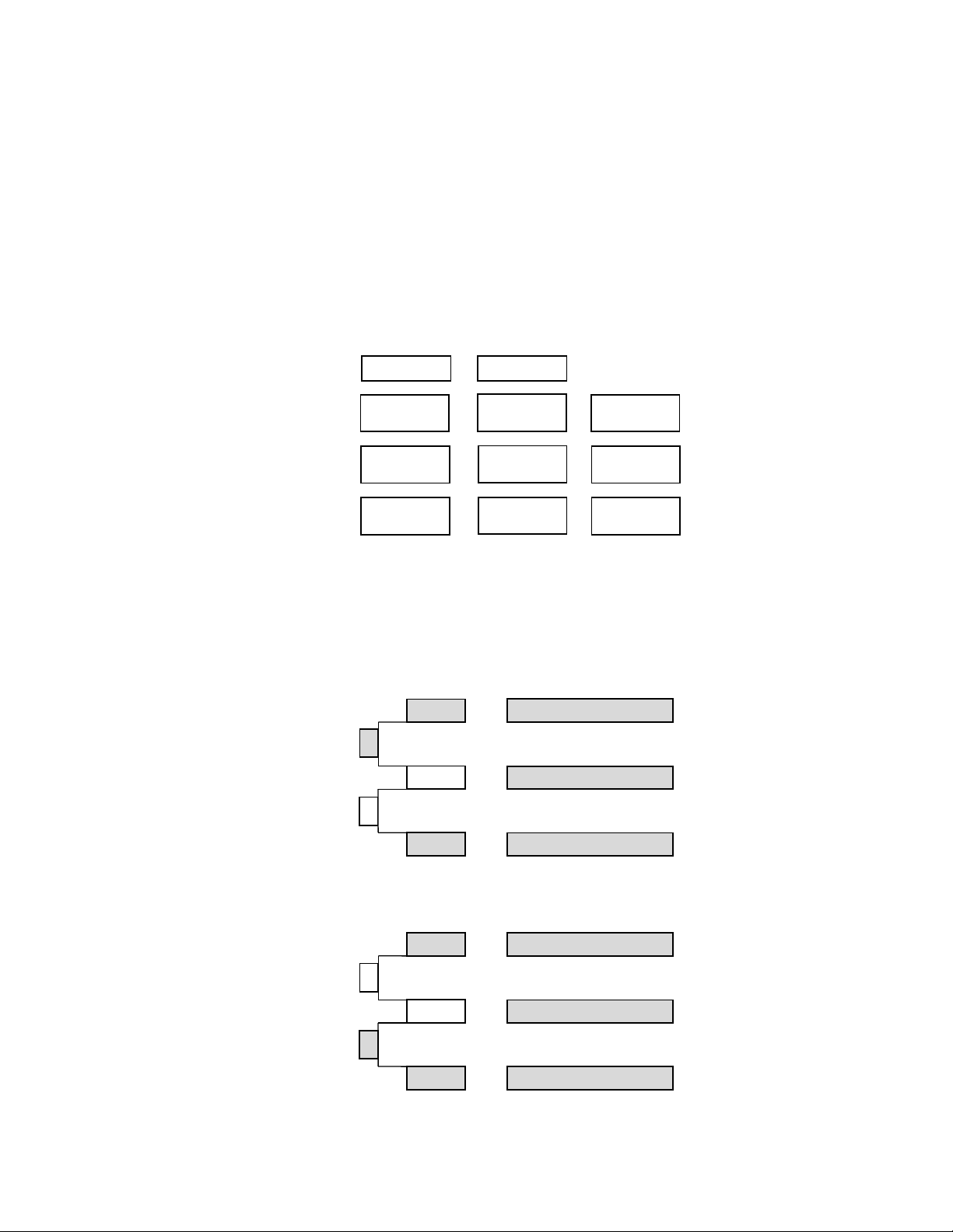
Membrane Switch Panel Configuration
Figure 1
To configure a common module to two switches, place the jumper on the PCB at the location
indicated and plug the syrup module into the respective connector as shown by the shaded squares
in Figure 2. For a unit where three modules are plumbed to a single nozzle, no jumper is used. The
module connectors on the PCB correspond to the switches on the membrane panel as shown above
when no jumpers are used.
Membrane / PCB Jumper Configurations
Figure 2
SODA
SW 4
SW 5
WATER
SW 1
POUR CANCEL
SMALL
MEDIUM
LARGE SW 3
SW 1 = MOD 1
SW 1
SW 2
JP1
SW 2
SW 2 = MOD 1
JP2
SW 3
SW 1
SW 3 = MOD 2
SW 1 = MOD 1
JP1
SW 2
SW 2 = MOD 2
JP2
SW 3
SW 3 = MOD 2
Page 10

5.2 CARB/PLAIN WATER CONFIGURATION
The following plumbing configurations are possible. Plain water is dispensed from the left nozzle
only. To select whether a flavor is carbonated or not, plug the respective syrup module into the
connector marked "Carb" or "PW" for that switch (SW4 or SW5, see Figure 1 and Section 9.7).
A. Four Flavor
4-0: All flavors are carbonated; plain water available from water button only; unused switch on
right side may be jumpered per Section 5.1;
3-1: Two (2) flavors on right nozzle carbonated; one (1) flavor on left nozzle carbonated;
one (1) flavor on left nozzle plain water; unused switch on right side may be jumpered per
Section 5.1;
2-2: Two (2) flavors on right nozzle carbonated; two (2) flavors on left nozzle plain water;
unused switch on right side may be jumpered per Section 5.1.
B. Five Flavor
5-0: All flavors are carbonated; plain water available from water button only; no jumper used;
4-1: Three (3) flavors on right nozzle carbonated; one (1) flavor on left nozzle carbonated;
one (1) flavor on left nozzle plain water; no jumper used;
3-2: Three (3) flavors on right nozzle carbonated; two (2) flavors on left nozzle plain water; no
jumper used.
5.3 PORTION CONTROL FEATURE
The middle column of switches selects portion control sizing when programmed (see Figure 1). The
pour size is selected by pressing and releasing the desired size first, and then the desired flavor
switch is pressed and released to start the dispense. The LED will light up until the flavor button is
pressed. Size preference is given to the last switch pressed. Pressing pour cancel at any time
deselects the size and stops the dispense. The individual flavor switches will operate manually if no
size selection is made.
A. PROGRAMMING PROCEDURE
1. To turn the Portion Control feature on, enter the programming mode by simultaneously
pressing and holding the lower two switches (Medium and Large, see Figure 1) until the
LED starts blinking, then release the switches. The LED will continue blinking while in
programming mode.
2. Put desired amount of ice in cup. Place cup under nozzle, press and release selected size
switch (Small, Medium, or Large), press and hold a flavor switch until the cup fills to the
desired level, then release the switch.
3. Wait for the foam to settle, then actuate the flavor switch again to set Top-Off.
4. Repeat Steps 2 and 3 for the other two drink sizes.
5. Repeat Steps 2, 3 and 4 for all other flavors.
6. After programming all drink sizes, press and release the Pour Cancel switch to return to the
operational mode. The LED will stop blinking.
7. To turn the Portion Control feature off, enter the programming mode (Step 5.3.A.1), and then
press and hold the Small and Medium switches until the LED stops blinking.
8. If Top-Off is not desired or required, the following steps must be followed:
a. Follow steps 5.3.A.1 and 5.3.A.2 above.
b. Repeat Step 5.3.A.2 for remaining drink sizes.
c. After actuating the last selected size switch, momentarily actuate one of the other size
switches. This will signal the microprocessor that all selected sizes are complete.
d. Repeat Step 5.3.A.6 above.
9. To change a dispense size, use the above procedure for the selected size; it is not
necessary to reprogram every size.
6. LANCER FLOW CONTROL VALVE MODULE (LFCV) ADJUSTMENT AND MAINTENANCE
6.1 GENERAL
The water flow for the Model 600 with Flow Control Modules may be adjusted from 1.20 oz/sec
(36 ml/sec) to 2.00 oz/sec (59 ml/sec) and the syrup flow may be adjusted from .25 oz/sec
7
Page 11

(7.4 ml/sec) to .40 oz/sec (11.8 ml/sec) to obtain a finished drink flow rate from 1.45 oz/sec
(41 ml/sec) to 2.40 oz/sec (71 ml/sec). Adjusting the flow control clockwise will increase the flow,
while turning it counter-clockwise will decrease the flow. The water flow control modules are gray
in color and are plumbed to the center fitting on the nozzle. The syrup flow control modules are
black and are plumbed to the three outer fittings on the nozzle. The unit should have been running
for at least one hour before attempting to set ratio. The drink temperature should be no higher than
40° F (4.4° C) when the ratio is set.
6.2 ADJUSTING WATER FLOW
A. Remove screws under Valve Shroud and open the Valve Shroud to expose the valve modules.
B. Disconnect the syrup modules from the PCB to disable syrup flow.
C. Hold a Lancer brix cup under the nozzle and dispense water into the cup for four seconds.
Divide number of ounces (ml) of water in cup by four to determine water flow rate per second.
D. To obtain desired flow, use a screwdriver to adjust the water flow control. Recheck as
necessary.
E. Repeat process for other nozzle and water flow controls.
6.3 ADJUSTING SYRUP FLOW
A. Reconnect syrup modules to PCB.
B. Remove nozzle by twisting counter-clockwise and pulling down.
C. Install the Model 600 syrup separator (54-0282) by engaging tangs on nozzle body and turning
clockwise. Lubrication of the separator seal is recommended (use 111 lubricant or another FDA
approved lubricant). Activate valves momentarily to fill the separator tube.
D. Hold the brix cup under the separator and dispense syrup and water into the cup.
E. Use a screwdriver to obtain the proper brix by adjusting the syrup flow control. Recheck as
necessary.
F. Repeat process for other syrup modules plumbed to the nozzle.
G. Remove separator, replace nozzle, and repeat for other nozzle.
H. After all modules are brixed, close Valve Shroud and replace screws.
6.4 CLEANING AND SANITIZING PROCEDURES
A. VALVE AND SYSTEM SANITIZING
1. The complete valve and dispenser system must be sanitized during initial installation.
Follow the manufacturer’s instructions when scheduling and conducting dispenser
sanitizing. The valve may remain on the dispenser during the sanitizing process.
2. To purge syrup, shut off water at backblock and hold keypad switch down for five (5)
seconds. Syrup will purge for as long as the keypad switch is held down.
6.5 DAILY NOZZLE/DIFFUSER CLEANING (SEE FIGURE 3)
A. The Multiflavor Nozzles (MFN) supplied on your Lancer 600 dispenser require low
maintenance. They are “mix in air” nozzles which means that the syrup/soda water interaction
begins after each of the two fluids leave the confines of the nozzle. Therefore, bacterial growth
should not occur within the syrup portion of the nozzle. The Lancer MFN is a “wipe clean”
design.
B. Use the following procedure to clean the nozzle assembly each day:
1. Remove nozzle housing by twisting it counter-clockwise and pulling it down.
2. Wash the nozzle with warm water.
3. Wet a clean cloth in warm, soapy water.
4. While the nozzle housing is removed, wipe down the perimeter and end of the nozzle body.
5. Rinse nozzle body with clean warm water and towel dry.
CAUTION
USE CARE TO INSURE O-RING IS NOT TORN OR OTHERWISE DAMAGED. IF DAMAGED,
REPLACE O-RING.
6. Make certain the nozzle o-ring is in place around the nozzle mounting area on the valve. If
necessary, slide a new nozzle o-ring (PN 02-0228) onto the nozzle mounting area.
7. If needed, apply 111 lubricant (or another FDA approved lubricant) to the o-ring on the
8
Page 12

nozzle body.
8. Install the nozzle by inserting it into the bottom plate and twisting it clockwise to lock it in
place.
6.6 MONTHLY NOZZLE/DIFFUSER SANITIZING
Use the following procedure to sanitize the nozzle housing once a month (see also Section 3).
A. Cleaning Solution
Prepare a caustic-based (low sudsing, non-perfumed, and easily rinsed) detergent solution and
clean, potable water at a temperature of 90° to 110°F. The cleaning solution should be 2%
sodium hydroxide.
B. Sanitizing Solution
Prepare a chlorine solution (less than pH 7.0) containing 100 PPM available chlorine with clean,
potable water at a temperature of 90° to 110°F. Any sanitizing solution may be used as long as
it is prepared in accordance with the manufacturer’s written recommendations and safety
guidelines, and provides 100 PPM available chlorine.
C. Cleaning Procedure
CAUTION
BE CAREFUL NOT TO GET SANITIZING SOLUTION ON THE CIRCUIT BOARD.
1. Disconnect power, so the valve will not be inadvertently activated while cleaning.
2. Remove nozzle housing by twisting it counter-clockwise and pulling it down.
3. Wash the nozzle housing with the cleaning solution.
4. Immerse the nozzle housing in a bath of the sanitizing solution for 15 minutes.
5. While the parts are in the sanitizing solution, visually inspect around the nozzle mounting
area on the valve for syrup residue. Using a cloth or nozzle brush and warm water, clean
this area.
6. Wipe off the valve shroud assembly and any other areas that may have been splashed by
syrup.
7. Wearing sanitary gloves, remove, drain, and air dry the nozzle housing.
8. Make certain the nozzle o-ring, is in place around the nozzle mounting area on the valve. If
necessary, slide a new nozzle o-ring (PN 02-0228) onto the nozzle mounting area. (Wear
sanitary gloves while handling the o-ring.) If needed, apply 111 lubricant (or another FDA
approved lubricant) to the o-ring.
9. Wearing sanitary gloves, install the nozzle housing by inserting it into the nozzle body and
twisting it clockwise to lock it in place.
10. Connect power and replace cover.
11. Draw drinks to flush residual sanitizing solution. Taste the beverage to verify that there is
no off taste. If an off taste is found, additional flushing may be required.
6.7 VALVE (SYRUP MODULE OR SODA MODULE)
A. Removal from Back Block
1. Raise valve shroud and lock in place.
2. Turn back block shut-off to the closed position (counter clockwise rotation).
3. Lower shroud and activate the valve pushbutton to relieve pressure.
4. Again, raise valve shroud and lock in place.
5. Unplug valve harness from PCB.
6. Raise valve retainer.
NOTE
The retainer cannot be pulled up until the back block shut-off is properly closed.
7. Pull the valve off of the back block.
9
Page 13

10
B. Mounting on Back Block
CAUTION
USE CARE TO INSURE O-RING IS NOT TORN OR OTHERWISE DAMAGED. IF DAMAGED,
REPLACE O-RING.
1. Check o-ring on back block. Replace o-ring, if necessary.
2. Apply 111 Lubricant (or another FDA approved lubricant) to o-ring, if necessary.
3. Press valve into the back block.
4. Lower the valve retainer to lock the valve in place.
5. Turn the back block shut-off to the open position (clockwise rotation).
6. Connect the valve harness to the proper position on the PCB.
7. Lower valve shroud.
6.8 NOZZLE HOUSING (SEE FIGURE 3)
A. Removal
1. Remove nozzle housing, by twisting it counter-clockwise and
pulling it in a downward direction.
2. Remove nozzle o-ring, if needed.
B. Assembly
1. Slide nozzle o-ring over the nozzle mount on the underside of
the valve.
2. Slide o-ring into the groove on the end of the nozzle body
assembly, if necessary.
3. Apply 111 Lubricant to o-ring, as required.
4. Install nozzle housing by inserting it onto the nozzle body and
twisting it in a clockwise direction to lock it into place.
Multiflavor Nozzle (MFN)
Figure 3
6.9 NOZZLE BODY AND FITTINGS (SEE FIGURES 4 AND 5)
A. To access the top of the nozzle body, remove screws under valve plate, raise valve shroud and
lock into place.
B. Each nozzle accepts four (4) fittings. The center nozzle port must always have the water fitting
installed. The outer ports (numbered 1 through 3) are for syrup fittings.
NOTE
When using thicker viscosity syrups, do NOT install syrup in Port #1. To achieve the
proper ratio, it may be necessary to use a fitting with an orifice larger than the standard
fitting.
C. Use a plug (PN 01-2004) in all unused syrup ports to keep debris from entering the unused
ports.
Water
Fitting
Syrup
Fitting
Water
Fitting
Syrup
Fitting
Water and Syrup Fittings
Figure 4
View Looking Down at Nozzle Ports
Figure 5
Page 14

7. WATER PUMP
7.1 The water pump contains a screen to prevent debris from entering the dispenser. Periodically,
according to the local water quality, the screen should be removed and cleaned.
A. To clean the screen, remove the water pump.
B. Remove screen from the outlet port.
C. Clean screen and reinstall screen in the outlet port.
D. Reinstall water pump in dispenser.
NOTES
11
Page 15

12
8. TROUBLESHOOTING
TROUBLE
CAUSE REMEDY
8.1 Miscellaneous leakage. A. Gap between parts. A. Tighten appropriate retaining
screws.
B. Damaged or improperly B. Replace or adjust appropriate
installed o-rings or seals. o-rings and/or seals.
8.2 Insufficient water flow. A. Insufficient incoming supply A. Verify incoming supply water
water and/or pressure. pressure is at zero (0) PSI flowing.
B. Reduced Flow B. Remove water pump. Remove
screen from outlet port and check
for debris/clogging. Clean screen,
as necessary, and reinstall screen
in outlet port. Reinstall water
pump.
8.3 Insufficient syrup flow. A. Insufficient CO
2 pressure to A. Adjust CO
2 pressure to 80 PSI for
syrup pumps or figals. internal BIB pumps. For remote
pumps, check manufacturer’s
recommendations or guidelines for
highest allowable CO
2 pressure.
8.4 No product dispensed. A. Water and syrup shutoffs on A. Open shutoffs fully.
mounting block not fully open.
B. The key switch on an electric B. Turn key switch to ON position.
valve is in the OFF position.
C. Dispenser supply sufficient C. Check dispenser for freeze-up
but no flow at back block. or other problems.
D. Power to circuit board D. Reset circuit breaker on top of.
interrupted. control box. If breaker trips again,
refer to Section 8.22. Also, check
connection J10 on circuit board and
check Fuse F2 on PCB.
E. Valves not receiving power. E. Check connectors J2 and J6 on
circuit board. Check connections at
valve.
F. Keypad inoperative. F. Check connection J13 on circuit
board. Configure valve to different
switch. If product dispenses at the
new switch but not the old switch,
replace keypad.
8.5 Water only dispensed; A. Water or syrup shutoff on A. Open shutoff fully.
no syrup; or syrup only mounting block not fully open.
dispensed; no water. B. Improper or inadequate water B. Remove valve from mounting block
or syrup supply. and open shutoffs slightly and
check water and syrup supply. If
no supply, check dispenser for
freeze-up or other problems.
Ensure BIB connection is engaged.
C. BIB supply too far from C. Check that BIB supply is within
dispenser. eight (8) feet (2.4 m) of the
dispenser.
D. CO2 pressure too low. D. Check the CO2 pressure to the
pump manifold to ensure it is
between 70-80 PSI.
E. Stalled or inoperative BIB E. Check CO2 pressure and/or
pump. replace pump.
F. Kinked line. F. Remove kink or replace line.
8.6 Valve will not shut off. A. Keypad may be sticking. A. Correct or replace keypad. Check
for entrapped air behind keypad.
Gently raise key pad and roll down
to remove trapped air.
Page 16

TROUBLE CAUSE REMEDY
13
8.7 Syrup only dispensed. A. Improper water flow to A. Check for water flow to dispenser
No water, but CO2 gas dispenser. (see Section 8.2).
dispensed with syrup. B. Carbonator pump motor has B. Reset by turning the unit OFF and
timed out. then ON, by using the ON/OFF
switch on top of the unit, or
unplugging unit momentarily.
C. Blown fuse on circuit board. C. Check Fuse F1 on circuit board.
D. Liquid level probe not D. Check connections of liquid level
connected properly to PCB. probe to PCB assembly.
E. Faulty PCB assembly. E. Replace PCB assembly.
F. Faulty liquid level probe. F. Replace liquid level probe.
G. Water bath frozen. G. Thaw water bath and repair faulty
component. (See refrigeration
related symptoms.)
H. Water line frozen. H. See Section 8.11.
8.8 Dispenser does not A. Membrane switch A. Reconfigure membrane switch
dispense proper syrup configuration is wrong. following steps in Section 5.
and/or water from B. Tubing is improperly routed B. Move water and syrup fittings to
proper nozzle. from module to nozzles. proper nozzle.
8.9 Excessive foaming. A. Incoming water or syrup A. Correct prior to dispenser.
temperature too high. Consider larger dispenser or
pre-cooler.
B. CO
2 pressure too high. B. Adjust CO
2 pressure downward,
but not less than 70 PSI.
C. Air in BIB lines. C. Bleed air from BIB lines.
D. Poor quality ice. D. Check quality of ice used in drink.
E. High beverage temperature. E. Check refrigeration system.
8.10 Water continually A. Loose water connection(s). A. Tighten water connection(s).
overflows from water B. Flare seal washer leaks. B. Replace flare seal washer.
bath into drip tray. C. Faulty water coil. C. Replace water coil.
8.11 Compressor starts and A. PCB malfunctioning or faulty A. Disconnect ice bank probe from
continues to run until ice bank probe. PCB.
freeze up and will not 1. If compressor continues to run,
cut off. check relay in control box on
refrigeration deck. If stuck
closed, replace relay. If not
stuck, replace circuit board.
2. If compressor stops, replace
ice bank probe.
B. Ice bank probe positioned B. Check positioning of ice bank
improperly. probe, and replace if needed.
C. Ice bank probe shorted to ground. C. Replace ice bank probe.
NOTE
: First check to ensure that the three (3) minute carbonator timer has not timed out. Turn unit
OFF and then ON. If the pump shuts off in less than 30 seconds, the dispenser is not frozen.
8.12 Warm drinks. A. Restricted airflow. A. Check clearance around sides,
top, and inlet of unit. Remove
objects blocking airflow through
grill.
B. Dispenser connected to hot B. Switch to cold water supply.
water supply.
C. Refrigeration system not C. See Sections 8.13 - 8.17.
running.
D. Refrigerant leak. D. Repair and recharge.
E. Condenser fan motor not E. Replace condenser fan motor.
working.
F. Dirty condenser. F. Clean condenser.
G. Dispenser capacity exceeded. G. Add pre-cooler or replace with
larger dispenser.
Page 17

TROUBLE CAUSE REMEDY
8.13 Compressor does not A. There is a five (5) minute A. Allow for five (5) minute delay to
start (no hum), compressor and condenser lapse.
condenser fan motor fan delay.
does not run and no B. Faulty refrigeration relay PCB. B. Replace refrigeration relay PCB in
ice bank. control box.
C. Ice bank probe not completely C. Fill water reservoir until water
submerged. flows from overflow tube.
D. Circuit breaker tripped. D. Reset breaker. If problem persists:
1. Determine reason and correct.
2. Electrical circuit overloaded;
switch to another circuit.
E. Inadequate voltage. E. Measure voltage across common
and run terminal on compressor.
Voltage must not drop below 90%
of rated voltage.
F. PCB malfunctioning. F. Replace PCB assembly.
G. Incorrect wiring. G. Refer to wiring diagram and
correct.
H. Faulty ice bank probe. H. Replace ice bank probe.
I. Transformer failure. I. Reset circuit breaker on top of
control box. If breaker trips again,
see Section 8.22.
J. Ice bank probe not connected J. Connect ice bank probe to PCB.
properly to PCB.
8.14 Compressor does not A. Compressor relay or A. Replace compressor relay or
start (no hum), but overload malfunctioning. overload.
condenser fan motor B. Inadequate voltage. B. Measure voltage across common
runs. and run terminal on compressor.
Voltage must not drop below 90%
of rated voltage.
C. Incorrect wiring. C. Refer to wiring diagram and correct.
D. Compressor malfunctioning. D. Replace compressor.
8.15 Compressor does not A. Inadequate voltage. A. Measure voltage across common
start but hums. and run terminal on compressor.
Voltage must not drop below 90%
of rated voltage.
B. Incorrect wiring. B. Refer to wiring diagram and correct.
C. Compressor relay C. Replace compressor relay. Be sure
malfunctioning. to use correct relay. Failure to use
correct relay will cause compressor
failure.
D. Compressor malfunctioning. D. Replace compressor or deck.
8.16 Compressor starts but A. Inadequate voltage. A. Measure voltage across common
does not switch off start and run terminal on compressor.
winding (will run for only B. Incorrect wiring. B. Refer to wiring diagram and correct.
a few seconds before C. Compressor relay C. Replace compressor relay. Be sure
internal overload malfunctioning. to use correct relay. Failure to use
switches compressor correct relay will cause compressor
off). failure.
8.17 Compressor starts and A. Dirty condenser. A. Clean the condenser.
runs a short time but B. Insufficient or blocked air B. Remove all obstructions and allow
shuts off on overload. flow. for minimum clearances of eight (8)
inches (20.3 cm) over top.
C. Inadequate voltage. C. Measure voltage across common
and run terminal on compressor.
Voltage must not drop below 90%
of rated voltage.
D. Incorrect wiring. D. Refer to wiring diagram and correct.
E. Defective condenser fan E. Replace condenser fan motor.
motor.
Section 8.17 continued next page.
14
Page 18

Section 8.17 continued from previous page.
F. Refrigerant leak. F. Repair and recharge.
G. Compressor malfunctioning. G. Replace compressor.
8.18 Compressor runs A. Low water level in water A. Add water to water bath until water
normally, but water bath. runs out of overflow into drip tray.
line is frozen. B. Syrup in water bath. B. Drain water from water bath and
refill with clean water.
C. Water cage is out of position. C. Reposition water cage.
D. Low refrigerant charge/slow D. Find and repair leak. Recharge
refrigerant leak system.
8.19 Compressor cycles A. PCB malfunctioning A. Replace PCB assembly.
on and off frequently B. Defective probe. B. Replace probe.
during the initial C. Air flow blocked. C. Check to ensure proper air
pulldown and/or clearance is provided (see
normal operations. Section 1.4).
8.20 Plain water flow is A. Insufficient incoming supply A. Verify incoming supply water
insufficient. water and/or pressure. pressure is a minimum of zero (0)
PSI flowing.
8.21 Suspect faulty PCB. A. PCB not receiving proper A. Check power from transformer on
input voltage. pins 4 and 5 of J10.
B. Green light not flashing (off B. Replace PCB.
or continuously on).
C. Yellow lights off and green light C. Check fuses F1 and F2, and also
is on when key switch is on. connection at J10.
8.22 Circuit breaker tripping. A. Pump is shorted. A. Disconnect pump and restore
power. If breaker does trip, then
pump is OK. If breaker does not
trip, replace pump.
B. Refrigeration relay is bad. B. Detect short by disconnecting J10
connector (24VAC input) from
PCB. Restore power. If breaker
doesn’t trip, then replace
refrigeration relay. If breaker does
trip, then refrigeration relay is OK.
Reconnect J10 connector.
C. Secondary wire harness is C. Detect short by disconnecting both
bad. secondary transformer fastons and
restore power. If it does not trip,
locate short in secondary harness
between transformer and PCB.
D. Transformer failure. D. Detect short by disconnecting both
primary transformer fastons and
restore power. If breaker doesn’t
trip, replace transformer.
8.23 BIB pump does not A. Out of CO2, CO2 not turned A. Replace CO2 supply, turn on CO2
operate when on, or low CO2 pressure. supply, or adjust CO2 pressure to
dispensing valve is 70-80 PSI.
opened. B. Out of syrup. B. Replace syrup supply.
C. BIB connector not tight. C. Fasten connector tightly.
D. Kinks in syrup or gas lines. D. Straighten or replace lines.
8.24 BIB pump operates but A. Leak in syrup inlet or outlet A. Replace line.
no flow. line.
B. Defective BIB pump check B. Replace BIB pump.
valve.
8.25 BIB pump continues to A. Leak in suction line. A. Replace line.
operate when bag is B. Leaking o-ring on pump inlet B. Replace o-ring.
empty. fitting.
15
TROUBLE CAUSE REMEDY
Page 19

8.26 BIB pump fails to restart A. BIB connector not on tight. A. Tighten BIB connector.
after bag replacement. B. BIB connector is stopped up. B. Clean out or replace BIB
connector.
C. Kinks in syrup line. C. Straighten or replace line.
8.27 BIB pump fails to stop A. Leak in discharge line or A. Repair or replace discharge line.
when dispensing valve fittings.
is closed. B. Empty BIB. B. Replace BIB.
C. Air leak on inlet line or bag C. Repair or replace.
connector.
8.28 Low or no carbonation. A. Low or no CO
2. A. Check CO2 supply. Adjust CO
2
pressure to 70 PSI.
B. Excessive water pressure. B. Water regulator should be set at
50 PSI.
C. Low water pressure. C. Must be 25 PSIG flowing with
carbonator pump running.
D. Worn or defective carbonator D. Replace carbonator pump.
pump.
8.29 Carbonator pump not A. Timed out. A. Check water supply; turn machine
running. off and on.
B. Fuse blown on PCB. B. Replace fuse F1 on PCB.
C. Faulty carbonator probe. C. Disconnect J14 connector from
PCB. If pump runs with probe
disconnected but will not run with
carbonator empty and probe
connected, replace probe.
D. Air in carbonator. D. Purge carbonator (see
Section 1.14).
E. Faulty PCB. E. Replace PCB.
NOTES
16
TROUBLE CAUSE REMEDY
Page 20

17
9. ILLUSTRATIONS, PARTS LISTINGS, AND WIRING DIAGRAMS
9.1 COMPRESSOR DECK ASSEMBLY
32
39
47
13
20
17
10
38
18
22
29
31
6
8
34
35
36
28
5
1
27
2
42
37
46
33
45
40
48
3
4
7
25
12
11
43
30
14
9
24
49
44
16
21
19
41
15
23
26
Page 21

ITEM P
ART NO. DESCRIPTION
- 82-2738 Deck Assy, Refrigeration,
115V/60Hz
- 82-2739 Deck Assy, Refrigeration,
220V/60Hz
- 82-1961 Deck Assy, Refrigeration,
230V/50Hz
- 82-2737 Deck Assy, Refrigeration,
100V/50-60Hz
1 23-1194 Plate Assy, Compressor Deck,
600
2 50-0288 Insulation, Compressor Deck,
600
3 82-1950 Coil Assy, Evaporator, 600
CCD
4 52-1773 EIBC Probe Assy with Springs
5 02-0114 Grommet, Compressor
6 04-0537 Washer, 0.467 ID x 0.923 OD
x 0.060 THK
7 04-0394 Screw, 6 - 32 x 0.500, Phillips
8 03-0150 Retainer, Clip, Convertible
9 23-1112 Condenser, CCD, 600
10 82-2731 Agitator Assy, 230V/50-60Hz
- 82-2730 Agitator Assy, 115V/60Hz
- 82-2729 Agitator Assy, 100V/50-60Hz
11 04-0504 8 - 18 x 0.375, Phillips
12 25-0073 Transformer, 275VA,
220-240V/50-60Hz
- 25-0072 Transformer, 275VA,
115V/60Hz
- 25-0074 Transformer, 275VA,
100V/50-60Hz
13 52-2593 Control Box Assy, 600 CCD
14 51-5380 Shroud Assy, Fan, 600
15 82-2735 Fan Assy, 230V/50-60Hz, 600
- 82-2734 Fan Assy, 115V/60Hz
- 82-2733 Fan Assy, 100V/50-60Hz
REF 07-0532 Fan Blade, 7.75”, CW, UB,
30 Degree
REF 02-0413 Silencer, 9W, Fan Motor
REF 04-0060 Nut, Flat
16 23-1144 Dryer/Cap Assy, 72”
17 47-2238 Tube, Process, Compressor,
600
18 47-2237 Tube, Suction, 600 CCD
19 47-0344 Process Tube, Dryer, 600
20 47-1655 Tube, High Side, 600
21 47-1656 Tube, Condenser, Out, 600
22 51-0061 Accumulator, 0.375 Holes
23 30-6844 Retainer, Baffle, Condenser,
600
24 50-0322 Baffle, Condenser, Side, 600
25 50-0325 Baffle, Condenser, Top, 600
26 04-0518 Rivet, 0.125 DIA x 0.328 LG,
DH
27 02-0040 Seal, Extrusion
28 02-0041 Seal
29 50-0211 Boot, 6”, Delta II
30 04-0059 Screw, 8 - 36 x 0.375, Phillips
31 51-5423 Handle, Deck, Compressor,
600
32 88-0013 Insulation, Tubular, 0.375 ID x
0.250 Wall
33 04-0754 Nut, Torq-Patch, 5/16 - 18 with
Washer
34 04-0576 Washer, Lock, Internal Tooth,
No. 8, Type A, Steel
35 04-0110 Nut, 8 - 32
36 06-0877 Label, GROUND
37 04-0753 Nut, Torq-Patch, 1/4 - 20 with
Washer
38 83-0047 Compressor Assy, 1/4HP,
240 - 220V/50Hz
REF 12-0250 Overload
REF 12-0060 Relay
- 83-0045 Compressor Assy, 1/4HP,
115V/60Hz
REF 12-0250 Overload
REF 12-0026 Relay
- 83-0046 Compressor Assy, 1/4HP,
208 - 230V/60Hz
REF 12-0251 Overload
REF 12-0252 Relay
REF 12-0261 Start Capacitor
- 83-0043 Compressor Assy, 1/4HP,
100V/50-60Hz
REF 12-0248 Overload
REF 12-0249 Relay
39 12-0330 Circuit Breaker, PNL MNT, 3
Amp (230V)
- 12-0345 Circuit Breaker, PNL MNT, 5
Amp (115V, 100V)
40 50-0287 Insulation, Carbonator Deck
41 50-0347 Baffle, Condensor, Bottom
42 04-0574 Washer, Lock, 5/16
43 30-6864 Bracket, Pump
44 02-0438 Grommet, Pump Bracket
45 04-0605 Washer, #8, Flat
46 04-0339 Screw, 10 - 32 x 0.750
47 52-2206 Lead Assy, Primary to Circuit
Breaker
- 50-0348 Insulation, Fill Hole
48 30-8228/01 Plate, Fill, 600CCD
49 50-0362 Insulation Plate, Fill, 600CCD
18
9.1 COMPRESSOR DECK ASSEMBLY (CONTINUED)
ITEM PART NO. DESCRIPTION
Page 22

9.2 MINIPUMP ASSEMBLY (FIVE FLAVOR, PN 82-3095; FOUR FLAVOR, 82-3095-04)
2
19
1
18
10
17
16
9
6
10
15
14
9
5
7
3
3
3
4
5
9
8
10
6
7
5
3
11
12
13
11
Page 23

9.2 MINIPUMP ASSEMBLY (FIVE FLAVOR, PN 82-3095; FOUR FLAVOR, 82-3095-04)
(CONTINUED)
20
ITEM PART NO. DESCRIPTION
1 30-7857 Plate, Minipump Base
2 04-0504 Screw, 8 - 18 x 0.375
3 04-0275 Screw, 8 - 16 x 0.427
4 01-0215 Stem, 5/32, Hose
5 07-0409 Clamp, Oetiker, 31/64
6 08-0029 Tubing, Inner Braided, 0.250 ID x
0.437 OD
7 01-1483 Elbow Assy, Syrup, 1/4 Barb
8 01-0222 Nut, Swivel, 7/16 - 20
9 07-0441 Clamp, Oetiker, 9/32
10 08-0036 Tube, CO
2
11 04-0359 Screw, 8 - 32 x 3.100
12 02-0005 O-Ring, 2-010
13 54-0091 Manifold SubAssy, 5 Flavor,
Black
-- 54-0093 Manifold SubAssy, 4 Flavor,
Natural
14 01-1325/01 Fitting Assy, CO2, Check
15 82-0251 Pump Assy, Mini
16 01-1072 Adaptor Assy, Elbow
17 54-0092 Manifold SubAssy, Gray
18 05-0604 Plug, CO
2 Manifold
Page 24

9.3 SERIES 600 LFCV CABINET ASSEMBLY
21
15
1
25
2
13
12
11
10
26
14
15
26
9
25
20
3
17
29
30
4
15
5
6
15
22
23
28
18
21
19
27
26
24
7
25
8
16
Page 25

ITEM PART NO. DESCRIPTION
1 82-2728 Top Cover Assy
2 42-0082 Foamed Tank Assy
3 51-5412/01 Cabinet Wrapper Assy
4 30-6783/01 Tubing Cover Plate
5 30-6790 Front Support Plate
6 30-6479 Drip Tray Bracket
7 05-1341 Drip Tray
8 05-1573 Cup Rest
9 30-8152 Faucet Plate
10 05-0679 Drain Retainer
11 05-0677 Drain Plug
12 02-0221 O-Ring
13 02-0089 O-Ring
14 08-0100 Overflow Tube
15 04-1071 Screw, Taptite, 8 - 32 x 0.375
16 30-6481 Splash Plate
17 12-0097 Key Switch (Optional)
-- 05-1502 Plug, Key Hole
18 54-0271 Shroud Assy
19 05-1360 Plate, Valves
20 05-1464 Pin, Hinge, Shroud Assy
21 05-1465 Arm, Hinge, Shroud Assy
22 12-0281/01 Membrane Switch
23 04-0571 Screw, 4 - 20 x 0.375, PHD, PH
24 54-0260 Nozzle Assy, Multi-Flavor
25 04-0780 Screw, 6 - 32 x 0.750, PH, MS,
SS, PL
26 04-0470 Screw, 6 - 19 x 0.500
27 19-0266 Valve Assy, Syrup
28 19-0267 Valve Assy, Water
29 82-2317/01 Block, Mounting Assy
30 04-1089 Screw, 10 - 32 x 1.000
- 52-2255 Harness Assy, Key Switch
(Optional)
- 50-0362 Insulation, Fill Hole
- 01-2004 Plug Assy, Nozzle
- 30-8228/01 Fill Plate
- 52-2591 PCB Assy
9.3 SERIES 600 LFCV CABINET ASSEMBLY (CONTINUED)
22
Page 26

23
9.4 CARBONATOR PUMP BRACKET ASSEMBLY
ITEM
PART NO. DESCRIPTION
1 52-2212 Pump Assy Carbonator
2 02-0047 O-Ring
3 17-0512 Valve Assy, Ball, Water Inlet
4 02-0089 O-Ring
5 48-1795 Tube Assy, Inlet, Ball Valve
6 48-1674 Tube Assy, Inlet, Pump Inlet
7 30-6865 Mount, Carbonator Motor
8 04-0865 Screw, 10 - 24 x 0.375, HHD, SL
-- 48-2001 Tube Assy, Inlet, Pump, without
Ball Valve
7
6
8
4
5
3
4
2
1
Page 27

9.5 CONTROL HOUSING (PN 52-2593)
NOTE: Some full wire assemblies not
shown for clarity.
ITEM PART NO. DESCRIPTION
1 30-6810 Cover, Control Box
2 30-6809/02 Control Box
3 04-0504 Screw, 8 - 18 x 0.375
4 12-0089 Switch, Kill, SPDT
5 12-0418 Power Inlet
6 04-0477 Screw, 8 - 32 x 0.375
7 52-2594 Lead Assy, Fan Motor
8 52-2595 Lead Assy, Agitator Motor
9 52-2597 Lead Assy, Comp #2
10 52-2208 Lead Assy, Comp #1
11 52-2596 Lead Assy, 5 Pin, Control
- 52-2365 Lead Assy, Switch/Relay/Breaker
- 52-2366 Lead Assy, Terminal Block, Power
Inlet
- 52-2207 Lead Assy, Terminal Block/Primary
- 52-2367 Lead Assy, Terminal Block/Ground
- 12-0330 Circuit Breaker, 3A (230V)
- 12-0345 Circuit Breaker, 5A (115V)
12 13-0047 Standoff, Circuit Board
13 52-2592 PCB Assy, Relay
24
3
1
5
12
13
4
2
7
8
6
11
9
10
Page 28

9.6 SERIES 600 LFCV CARBONATOR, WATER/SYRUP LINE ASSEMBLIES
25
17
15
16
15
3
11
13
14
2
12
1
10
15
9
9
6
7
8
9
9
9
4
5
Page 29

26
ITEM PART NO. DESCRIPTION
1 82-1962/01 Carbonator Assy
2 02-0096 Washer, Flat Plastic Probe
3 52-2224 Carbonator Probe Assy
4 48-1807 Tube Assy, Syrup #1, with
Pumps
-- 48-1848 Tube Assy, Syrup #1, without
Pumps
5 48-1808 Tube Assy, Syrup #2, with
Pumps
-- 48-1849 Tube Assy, Syrup #2, without
Pumps
6 48-1809 Tube Assy, Syrup #3, with
Pumps
-- 48-1850 Tube Assy, Syrup #3, without
Pumps
7 48-1810 Tube Assy, Syrup #4, with
Pumps
-- 48-1851 Tube Assy, Syrup #4, without
Pumps
8 48-1811 Tube Assy, Syrup #5, with
Pumps
-- 48-1852 Tube Assy, Syrup #5, without
Pumps
9 02-0005 O-Ring
10 23-1259 Cage Assy
11 48-1405 Tube Assy, Water Option
12 17-0341 Check Valve Assy
- 01-0669 Body, Check Valve
- 01-0689 Sleeve
- 02-0003 O-Ring
- 03-0021 Spring
- 01-1466 Fitting, Check Valve
13 02-0047 O-Ring
14 05-0017 Flare Seal, 3/8
15 05-0011 Flare Seal, 7/16
16 17-0469 Relief Valve Assy, Carbonator
17 01-0424 Elbow, SS, 1/4 Barb x 1/4 S
Nut (No Pump Version Only)
- 88-0013 Insulation, Tube, 6.750
(Not Shown)
9.6 SERIES 600 LFCV CARBONATOR, WATER/SYRUP LINE ASSEMBLIES (CONTINUED)
Page 30

27
9.7 WIRING DIAGRAM, 600 LFCV, PN 06-2451
fi
PROBE
PROBE
ICE BANK
ELECTRONIC
CARBONATOR
KEYPAD
B
G
R
IMPORTANT
B
G
W
G
B
W
G
B
R
PUMP
J13
J14
J15
F2
F1
J11
SW1
SW4
J10
G
JP1
O
R
SW2
SW5
W
B
JP2
PW
CARB
SW3
J6
SODA
J7
WATER
J8
SODA
SM1
SM2
SM3
WM1
WM2
WM3
WATER AND SYRUP MODULES
SM4
SM5
600 LFCV
B
INLET WATER
B
G POWER
R
B
J1
B
BREAKER
CIRCUIT
O
B
B
B
T3T5T7
FAN
AGITATOR
T4
T6
COMPRESSOR
B / W
B / W
B
B / W
2
FAN
MOTOR
B
B
T9
T8
T10
TRANSFORMER
B / W
B / W
B
2
1
MOTOR
AGITATOR
NEUTRAL LINE
B / W
1
T1
T2
B / W
B
B
IS A 5 MINUTE DELAY BEFORE THE COMPRESSOR / FAN STARTS.
MOTOR. IF THE MOTOR HAS TIMED OUT, CHECK WATER SUPPLY AND
RESET BY MOMENTARILY DISCONNECTING POWER.
1. WHEN STARTING UNIT OR IF CURRENT IS INTERRUPTED, THERE
2. THERE IS A 3 MINUTE PROTECTION TIMER ON THE CARBONATION PUMP
LABEL, WIRING DIAGRAM
06-2514
B / W
POWER
B
SWITCH
B / W
COMPRESSOR
C
S
E
I
P
R
B
W
B / W
Page 31

(Continued from previous page)
EcuaLancer S.A. - Ecuador
Lancer Sales Company
Contact: Luciano Lopez
Sector Las Acacias
Luis De Beethoven #958
Y Capitan Rafael Ramos
Quito, Ecuador
Phone: 593-22-401-598, 400-937, 406-418
FAX: 593-22-400-535
e-mail: Llopez@ecnet.ec
Lancer Authorized Distributors
Eximport & Barter Co. - Caribbean
2101 S.W. 56th Terrace
Hollywood, FL 33023 USA
Phone: (954) 967-9999
FAX: (954) 967-9900
e-mail: edbrandao@aol.com
PromoVen, S.A. - Argentina
Contact: Rafael Mendoza
Juncal 858 - Piso 3 Depto. “L”
(1062) Buenos Aires
Argentina
Phone: (54.11)4394.7654
FAX: (54.11)4394.1193
e-mail: promoven@customw.com.ar
Bras Sulamericana LTDA. - Brasil
Contact: Fabio Queiroz
Rua. Dr. Ladislau Retti, 1400
Parque Alexandre
Cotia Sao Paulo - Brasil
CEP: 06714-150
Phone: 55-11-4612-1122
FAX: 55-11-4612-2219
e-mail: fabio.queiroz@bras.com.br
Lancer Chile Ltda. - Chile
Contact: Heriberto Concha
Vicuna Mackenna 3019, San Joaquin
Santiago, Chile
Phone: 56-2-552-1657
FAX: 56-2-552-1961
e-mail: hconcha@lancer-intl.com
Lancer Pacific
International Sales
6655 Lancer Blvd.
San Antonio, TX 78219
Phone: (210) 310-7000
FAX: (210) 310-7242
1-800-729-1500
e-mail: asia@lancercorp.com
Australia
Lancer Pacific Pty Ltd
5 Toogood Avenue
Beverley SA 5009
Australia
Phone: 61-8-8268-1388
FAX: 61-8-8268-1978
e-mail: ian-lunniss@lancer-pacific.com.au
steve-sotiriou@lancer-pacific.com.au
Lancer Pacific Pty Ltd
7 Slough Avenue
Silverwater, NSW, 2128
Sydney, Australia
Phone: 61-2-9648-6840
FAX: 61-2-9648-6850
e-mail: richard-abraham@lancer-
pacific.com.au
fiore-alvaro@lancer-pacific.com.au
(for Beer)
rob-burdock@lancer-pacific.com.au
(Senior Director - Asia)
R.B.P. Industrial Sales Inc - Philippines
Unit 20, Facilities Centre Bldg.
548 Shaw Blvd
Mandaluyong City, Philippines
Phone: 632-531-1215/1221/1289
FAX: 632-531-1271
e-mail: rbpsales@info.com.ph
Freser (S) Pte Ltd - Singapore
Blk 998 Toa Payoh North
#04-12/14
Singapore 318993
Phone: 65-6352-0943
FAX: 65-6352-8594
e-mail: fresersin@pacific.net.sg
Freser International Corporation - Taiwan
No. 76, Gui-Sui Street
Taipei 103, Taiwan R.O.C.
Phone: 886-2-2553-1555
FAX: 886-2-2553-2742
e-mail: allen@intl.freser.com.tw
Freser (Thailand) Co Ltd - Thailand
3/15 Moo 3, Soi Ruammitr
Tivanont Road, Banmai
Pakkred, Nonthaburi, 11120
Thailand
Phone: 662-961-9543
FAX: 662-961-9550
e-mail: prachat@asianet.co.th
Lancer - Indian Sub-Continent
India
Shabbir Shafiqui - Area Manager
India and Sub-Continent
B-7, Pannalal Silk Mill Compounds
78, LBS Marg, Bhandup (W)
Mumbai 400-078, India
Phone: 91-22-2561-6665
Cel No.: 91-98-2029-5252
FAX: 91-22-5637-4018
e-mail: shafiquis@vsnl.com
Lancer Authorized Distributors
Western Refrigeration Ltd - India
B-7, Pannalal Silk Mill Compounds
78 L.B.S. Marg, Bhandup (W)
Mumbai 400-078, India
Phone: 91-22-2561-6665
FAX: 91-22-2562-2257
e-mail: western@bom5.vsnl.net.in
Bengal Marketing Company - Bangladesh
Skylark Point (6th Floor)
Room #G-2
24/A Bijoy Nagar,
Dhaka-1000, Bangladesh
Phone: 880-2-934-2987
FAX: 880-2-935-0127
e-mail: bmc@dhaka.agni.com
Dynamic Equipment - Pakistan
Dynamic Equipment and Controls (Pvt.) Ltd.
F-1/23, Canal Cottages, Block-D.
New Muslim Town.
Lahore. Pakistan.
Phone: 0092-42-583-6737
0092-42-583-6787
FAX: 0092-42-586-7924
e-mail: info@dynamic-eqpt.com.pk
Lancer Pacific Pty Ltd
55 Keele Street
Collingwood
Melbourne Victoria 3066
Australia
Phone: 03 8415 1920
FAX: 03 8415 1929
e-mail: glenn-blakiston@lancer-pacific.com.au
Lancer Pacific Pty Ltd
Unit 31, 284 Musgrave Drive
Coopers Plains 4108
Queensland
Australia
Phone: 61-7-3274-5700
FAX: 61-7-3875-1805
e-mail: brett-thomson@lancer-pacific.com.au
New Zealand
Lancer Pacific Ltd
9 O’Rorke Street
Onehunga, Auckland
New Zealand
Phone: 64-9-634-3612
FAX: 64-9-634-1472
e-mail: phil-mason@lancer-pacific.com.au
Hong Kong
Patrick Co - Area Manager - Asia
Phone: 852-29670900
FAX: 852-30105882
e-mail: patrickco@lancer-asia.com
Lancer Authorized Distributors
Shanghai Freser International Co Ltd. China
1856, Hu Tai Road
Shanghai, 200436, China
Phone: 86-21-5650-3555
FAX: 86-21-5650-2666
e-mail: daniel@freser.com.cn
Freser (HK) Company Ltd - Hong Kong
Flat A, 24/F., Houston Industrial Bldg.
32-40 Wang Lung Street
Tsuen Wan, N. T., Hong Kong
Phone: 852-2408-2595
FAX: 852-2408-2605
e-mail: freserhk@netvigator.com
P.T. Ciptapratama Sentosamakmur Indonesia
JI. Anggrek Nelly Murni, Blok A - 39, Slipi
Jakarta 11480, Indonesia
Phone: 62-21-532-3737
FAX: 62-21-532-3666
e-mail: ciptasm@indosat.net.id
Hayakawa Sanki - Japan
Hayakawa Sanki, Inc.
1-13-13, Kayaba-cho
Nihonbashi, Chuo-ku
Tokyo, 103-0025
Japan
Phone: 03-5651-1481
FAX: 03-5651-1445
e-mail: SANKI10217@aol.com
Tahoe Corporation - Korea
Tahoe Corporation
2FL, 835-66 Yocksam-dong
Kangnam-Ku
Seoul, Korea
Phone: 82-2-557-5612, -5614
FAX: 82-2-557-5615
e-mail: tahoepark@netsgo.com
Freser (MALAYSIA) SDN. BHD. - Malaysia
No. 31, Jalan TPP 5/13, Taman
Perindustrian Puchong, Seksyen 5,
47100 Puchong, Selangor, Malaysia
Phone: 60-3-8061-6666
FAX: 60-3-8062-1007
e-mail: freser@tm.net.my
Directory of USA - Canada Offices,
International Offices, and Authorized Distributors (Continued)
28
Page 32

Lancer USA
Manufacturing Locations
Foster Road Facilities
6655 Lancer Blvd
San Antonio, TX 78219
Phone: (210) 310-7000
MFG FAX: (210) 310-7088
ENG FAX: (210) 310-7096
ACCT FAX: (210) 310-7091
PURCH FAX: (210) 310-7094
Lancer FBD
5620 Business Park
San Antonio, TX 78218
Phone: (210) 666-0544
FAX: (210) 666-2044
Lancer Ice Link
6655 Lancer Blvd
San Antonio, TX 78219
Phone: (210) 310-7174
FAX: (210) 310-7245
Remanufacturing
6655 Lancer Blvd
San Antonio, TX 78219
Phone: (210) 310-7356
FAX: (210) 310-7261
1-800-729-1550
Lancer North America
USA - Canada Sales
6655 Lancer Blvd.
San Antonio, TX 78219
Phone: (210) 310-7000
SALES FAX: (210) 310-7245
CUSTOMER SERVICE FAX: (210) 310-7250
1-800-729-1500
Georgia Office
1125 Northmeadow Parkway, Suite 116
Roswell, GA 30076
Phone: (770) 343-8828
FAX: (770) 475-8646
1-800-729-1750
Lancer Authorized Distributors
Advanced Beverage Solutions (ABS)
1425 South Wright Blvd.
Schaumburg, IL 60193
Phone: (847) 524-1707
(877) 814-2271
FAX: (847) 524-1710
www.absone.com
Bevco
6900 Camille Avenue
Oklahoma City, OK 73149
Phone: (405) 672-7770
FAX: (405) 672-7443
e-mail: info@bevcoinc.com
Joe Kirwan Company
119 White Oak Lane
Old Bridge, NJ 08857
Phone: (732) 679-1900
FAX: (732) 679-9236
e-mail: sales@jkirwan.com
L & M Beverage Equipment Co. Inc.
12510 Santa Fe Trail Drive
Lenexa, KS 66215
Phone: (913) 888-8988
FAX: (913) 888-9137
e-mail: L7mco@aol.com
(Update #43 - as of March 05, 2003)
Lancer Russia
Lancer Sales Company
Vyatskaya Street 27
Building 15, 4th Floor
125015 Moscow, Russia
Phone: 7-095-745-7108
FAX: 7-095-745-7109
Mobile Phone: 7-095-991-7778
7-095-139-0335
e-mail: lancer@online.ru
vdemkin@ktv.ru
Lancer Middle East / Africa
Elsayed Moniem - Technical Manager
Lancer Middle East/Africa
7 Mubarak Street
East Ain Shams 11311
Cairo, Egypt
Phone/FAX: 2-02-49-35-395
Mobile Phone (GSM): 2-010-500-4007
e-mail: elsayed_lancer@msn.com
Lancer Authorized Distributor
DispenseTech - South Africa
P.O. Box 17495
Sunward Park, 1470
South Africa
Phone: 27-11-397-7455
FAX: 27-11-397-7648
e-mail: david@dispensetech.co.za
Lancer Latin America
Latin America Sales
6655 Lancer Blvd.
San Antonio, TX 78219
Phone: (210) 310-7000
FAX: (210) 310-7245
1-800-729-1500
e-mail: latinamerica@lancercorp.com
Lancer de México, S.A. de C.V.
Contact: Gerardo Canales
Calle Lerdo De Tejada #544 PTE.
Col. Las Villas
San Nicolas De Los Garza, N.L.
Monterrey, N. L., México C.P. 66422
Phone: (52)-81-83-52-85-32
Phone: (52)-81-83-52-85-34
Phone: (52)-81-83-52-53-60
FAX: (52)-81-83-32-54-10
e-mail: direccion@lancer.com.mx
Lancer de México, S.A. de C.V.
Branch Office, Mexico City
Contact: Carlos Lopez
Lancer de Mexico S.A. de C.V.
Sucursal Mexico D.F.
Calle: Centeotl No. 112
Colonia: La Preciosa
Delegacion: Azcapotzalco
Mexico D.F. C.P. 02460
Phone: (52)-55-53-53-89-28
Phone: (52)-55-53-53-89-26
Phone: (52)-55-53-53-88-60
Phone: (52)-55-53-53-88-21
FAX: (52)-55-53-52-46-30
e-mail: lancer@prodigy.net.mx
Lancer de México, Branch Office, Cd. Juarez
Contact: Yolanda Puga
Lancer de Mexico
Camino de la Lomas # 4380
Col. Partido Iglesias
Cd. Juarez, CHIH, C.P. 32617
México
Phone and FAX: 521-605-00-86
Phone: 521-605-00-87
e-mail: cdjuarez@lancer.com.mx
(Continued on reverse)
Ernest F. Mariani Company
614 West 600 South
Salt Lake City, UT 84104
Phone: (801) 359-3744
FAX: (801) 531-9615
e-mail: febell@efmco.com, or
clay@efmco.com
Mark Powers & Company, Inc.
P.O. Box 72
1821 Henry Street
Guntersville, AL 35976
Phone: (256) 582-6620
FAX: (256) 582-8533
e-mail: sales@markpowers-and-company.com
Maurer Supply, Inc.
843 Rainier Avenue South
Seattle, WA 98144
Phone: (206) 323-8640
FAX: (206) 323-9286
e-mail: maurersupply@qwest.net
Simgo Ltd.
5122 Timberlea Blvd.
Mississauga, Ontario L4W 2S5
Canada
Phone: 905-602-5800
FAX: 905-602-5804
e-mail: simgo@simgo.com
Simgo (B.C.) Ltd.
16-8125 - 130th Street
Surrey, B.C. V3W 7X4
Canada
Phone: 604-590-4022
FAX: 604-590-1601
Lancer Europe
Belgium - European Central Office
Lancer Europe, S.A.
Mechelsesteenweg 592
B-1930 Zaventem
Belgium
Phone: 32-2-755-2390
FAX: 32-2-755-2399
e-mail: lancer.europe@glo.be
England
17 Bembridge Gardens
Ruislip, Middlesex
HA4 7ER, England
Phone: 44-1895672667
FAX: 44-1895637537
e-mail: court4lancer@msn.com
Hungary
H-2100 Gödöllõ
Isaszegi út 67
Hungary
Phone: 36-28-417-179
FAX: 36-28416-881
e-mail: bodolai@compuserve.com
Lancer Authorized Distributors
Complete Beverage Services, Ltd.
Republic of Ireland and Northern Ireland
Gortrush Industrial Estate
Omagh County Tyrone
Northern Ireland
Office: 44-1662 250 008
FAX: 44-1662-252-991
Intercom - Spain
Intercom
Avda. Concha Espina 8
28036 Madrid Spain
Phone: 34-91-564 6900
FAX: 34-91-564 3065
e-mail: jmorales@bevserv.com
29
Directory of USA - Canada Offices,
International Offices, and Authorized Distributors
Corporate Office
6655 Lancer Blvd. • San Antonio, Texas 78219 • 210-310-7000 • 1-800-729-1500 • FAX 210-310-7250
 Loading...