

Page 1
INSTALLATION AND SERVICE MANUAL
FOR
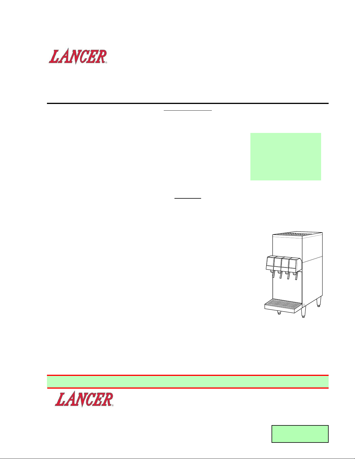
COUNTER ELECTRIC DISPENSER
LANCER SERIES 500
REV: 04/20/00
P.N. 28–0449
This manual is an initial issue
FAX ENGINEERING: • 210-310-7096
"Lancer" is the registered trademark of Lancer • Copyright — 2000 by Lancer, all rights reserved.
SPECIFICATIONS
DIMENSION
Width 10 3/8 inches (264 mm)
Depth 25 1/4 inches (641 mm)
Height (without legs) 22 15/16 inches (583 mm)
WEIGHT
Shipping 108 pounds (49.0 kg)
Empty 89 pounds (40.4 kg)
Operating 125 pounds (55.4 kg)
WATER REQUIREMENTS
CAUTION
IF WATER SOURCE EXCEEDS 60 PSIG (4.22 KG/CM2), A RECOMMENDED WATER REGULATOR
ASSEMBLY (PN 18-0253) MUST BE USED TO LIMIT WATER PRESSURE TO 60 PSIG (4.22 KG/CM2).
FAILURE TO USE REGULATOR WILL RESULT IN IMPROPER PERFORMANCE OF DISPENSER.
Minimum flowing pressure of 35 PSIG (2.46 kg/cm
2
, 2.41 BAR)
Maximum static pressure of 60 PSIG (4.22 kg/cm2, 4.14 BAR)
CARBON DIOXIDE (CO
2) REQUIREMENTS
Minimum pressure of 70 PSIG (4.92 kg/cm
2
, 4.83 BAR)
Maximum pressure of 80 PSIG (5.62 kg/cm2, 5.52 BAR)
ICE BANK WEIGHT 16 pounds (17.26 kg)
WATER BATH CAPACITY 5.1 gallons (19.3 liters)
COMPRESSOR ¼ HP Tecumseh, 115V/60Hz
AGITATOR MOTOR 15W, 115V
CONDENSER FAN MOTOR 9W, 115V
ICE BANK CONTROL Lancer Electronic Ice Bank Control
TRANSFORMER Basler, 115V (Primary)/24V (Secondary)
Optional 230V/50Hz and 240V/60Hz systems available.
DRINK CAPACITY
57 – 12 ounce drinks under 40°F (4.4°C) at four (4) drinks per minute with 75°F (23.9°C) ambient, inlet
water, and inlet syrup.
Please refer to the Lancer web
site (www.lancercorp.com)
for information relating to
Lancer Installation and
Service Manuals, Instruction
Sheets, Technical Bulletins,
Service Bulletins, etc.
6655 LANCER BLVD. • SAN ANTONIO, TEXAS 78219 USA • (210) 310-7000
FAX SALES
• NORTH AMERICA – 210-310-7245 • INTERNATIONAL SALES – 210-310-7242 • CUSTOMER SERVICE – 210-310-7242 •
• LATIN AMERICA – 210-310-7245 • EUROPE – 32-2-755-2399 • PACIFIC – 61-8-8268-1978 •
Page 2

TABLE OF CONTENTS
SPECIFICATIONS ...................................................................................................................................COVER
TABLE OF CONTENTS .....................................................................................................................................1
1. INSTALLATION ...........................................................................................................................................1
1.1 RECEIVING........................................................................................................................................1
1.2 UNPACKING ......................................................................................................................................2
1.3 INSTALLATION ..................................................................................................................................2
1.4 CONNECTING TO ELECTRICAL POWER .......................................................................................2
1.5 CONNECTING SUPPLY LINES TO SOURCES ................................................................................2
2. SCHEDULED MAINTENANCE ...................................................................................................................3
2.1 DAILY .................................................................................................................................................3
2.2 WEEKLY .............................................................................................................................................3
2.3 MONTHLY ..........................................................................................................................................3
2.4 EVERY SIX MONTHS........................................................................................................................3
2.5 YEARLY..............................................................................................................................................3
3. DISPENSER CLEANING AND SANITIZING ..............................................................................................3
3.1 AMBIENT PROCESS.........................................................................................................................3
3.2 VALVES ..............................................................................................................................................4
4. TROUBLESHOOTING.................................................................................................................................4
4.1 WATER LEAKAGE AROUND NOZZLE .............................................................................................4
4.2 LEAKAGE BETWEEN UPPER AND LOWER BODIES.....................................................................4
4.3 MISCELLANEOUS LEAKAGE ...........................................................................................................4
4.4 INSUFFICIENT WATER FLOW..........................................................................................................4
4.5 INSUFFICIENT SYRUP FLOW..........................................................................................................5
4.6 ERRATIC RATIO ................................................................................................................................5
4.7 NO PRODUCT DISPENSED .............................................................................................................5
4.8 WATER ONLY DISPENSED; NO SYRUP; OR SYRUP ONLY DISPENSED, NO WATER ...............5
4.9 VALVE WILL NOT SHUT OFF ...........................................................................................................5
4.10 EXCESSIVE FOAMING .....................................................................................................................5
4.11 COMPRESSOR DOES NOT START (NO HUM), BUT CONDENSER FAN
MOTOR RUNS...................................................................................................................................6
4.12 COMPRESSOR STARTS AND CONTINUES TO RUN UNTIL FREEZE UP
AND WILL NOT CUT OFF .................................................................................................................6
4.13 COMPRESSOR DOES NOT START BUT HUMS .............................................................................6
4.14 COMPRESSOR STARTS BUT DOES NOT SWITCH OFF START WINDING .................................6
4.15 COMPRESSOR STARTS AND RUNS A SHORT TIME BUT SHUTS OFF
ON OVERLOAD .................................................................................................................................6
4.16 COMPRESSOR AND CONDENSER FAN MOTOR WILL NOT START AFTER
FIVE (5) MINUTE POWER OFF DELAY (LANCER EIBC EXPORT ONLY) .....................................6
4.17 COMPRESSOR AND CONDENSER FAN MOTOR WILL NOT START AFTER
FIVE (5) MINUTE POWER OFF DELAY (LANCER EIBC USA ONLY).............................................6
4.18 WARM DRINKS..................................................................................................................................6
5. ILLUSTRATIONS, PARTS LISTINGS, AND WIRING DIAGRAMS............................................................7
5.1 500 CED WIRING DIAGRAM, 220-240V/50-60HZ, LANCER ELECTRONIC ICE
BANK CONTROL (INTERNATIONAL ONLY).....................................................................................7
5.2 500 CED WIRING DIAGRAM, 115V/60HZ, LANCER ELECTRONIC ICE BANK
CONTROL AND CONTROL HOUSING CONNECTIONS (USA ONLY) ............................................8
5.3 CABINET ASSEMBLY...................................................................................................................9-10
5.4 COMPRESSOR DECK ASSEMBLY ...........................................................................................11-12
1. INSTALLATION
1.1 RECEIVING
Each unit is completely tested under operating conditions and thoroughly inspected before
shipment. At the time of shipment, the carrier accepts the unit and any claim for damage must be
made with the carrier. Upon receiving unit(s) from the delivering carrier, carefully inspect carton for
visible indication of damage. If damage exists, have carrier note same on bill of lading and file a
claim with the carrier.
1
Page 3

1.2 UNPACKING
A. Remove cup rest by lifting out.
B. Remove splash plate by pulling forward at the bottom. Drip tray can be removed before
removing splash plate.
C. Remove drip tray by lifting out.
D. Remove shipping base. DO NOT LAY UNIT ON ITS SIDE OR BACK. DO NOT USE DRIP
TRAY FRAME FOR A HANDLE.
NOTE
If unit is to be transported, it is advisable to leave unit secured to plywood shipping base.
E. Inspect unit for concealed damage. If damage exists, notify delivering carrier note and file a
claim against the carrier.
1.3 INSTALLATION
The dispenser is designed to sit on a flat, supported surface capable of supporting a minimum
weight of 200 pounds (90.7 kg). It may be either counter or leg mounted. When the dispenser is to
be permanently bolted to the counter top, seal dispenser base to counter top with a silicone sealant
which provides a smooth and easily cleanable bond to the counter.
NOTE
NSF listed units must be sealed to the counter or have four (4) inch legs installed.
W
ARNING
FAILURE TO MAINTAIN PROPER AIR CLEARANCE WILL CAUSE THE COMPRESSOR TO
OVERHEAT AND WILL RESULT IN PREMATURE COMPONENT FAILURE.
Locate dispenser to allow approximately 15 inches (380 mm) of unobstructed space above and six
(6) inches (152 mm) of unobstructed space in back of the unit for proper air circulation and removal
of bonnet. Air is drawn in through the back grill and is exhausted out the top grill.
A. Position dispenser on counter.
B. Remove bonnet from the dispenser.
C. Remove insulation strip from in front of refrigeration deck. Fill tank with water until water comes
out of overflow tube. Replace insulation. Use bottled water where a water problem exists.
1.4 CONNECTING TO ELECTRICAL POWER
W
ARNING
THIS UNIT MUST BE PROPERLY ELECTRICALLY GROUNDED TO AVOID POSSIBLE FATAL
ELECTRICAL SHOCK OR SERIOUS INJURY TO THE OPERATOR. THE POWER CORD IS
PROVIDED WITH A THREE PRONG GROUNDED PLUG. IF A THREE-HOLE GROUNDED
ELECTRICAL OUTLET IS NOT AVAILABLE, USE AN APPROVED METHOD TO GROUND THE
UNIT.
DO NOT USE EXTENSION CORDS WITH THIS UNIT. DO NOT “GANG” TOGETHER WITH
OTHER ELECTRICAL DEVICES ON THE SAME OUTLET.
A. Check the dispenser serial number plate for unit's correct electrical requirements. Do not plug
into electrical outlet unless unit electrical configuration, located on serial plate, agrees with local
available power supply.
B. Route the power supply cord to a grounded electrical outlet of the proper voltage and amperage
rating, and plug in the unit. This will turn on the refrigeration system and allow it to start cooling
and allow ice bank to form while completing installation. Approximately four (4) hours are
required to form a full ice bank.
NOTE
Units equipped with an electronic ice bank control contain a five (5) minute delay. Compressor
and fan motor will not begin running until five (5) minutes after the unit is energized.
1.5 CONNECTING SUPPLY LINES TO SOURCES
A. Connect free end of plain water lines to water supply [must be 35 PSI (2.4 BAR) or more].
2
Page 4

B. Mark both ends of product and water lines and route to dispenser. Flush lines to be sure each
is clean. Failure to do so may result in clogging of valve(s), resulting in improper operation.
Connect lines to dispenser and secure using Oetiker clamps.
C. Route drain tube to dispenser.
D. Connect drain tube to drip tray and install on dispenser.
E. Turn on water supply.
F. Open all dispenser valves until air is bled from system.
G. Actuate valve until a smooth flow of water is obtained.
H. Check for leaks.
I. Connect free ends of product lines to proper tanks or bag-in-box.
J. Check for syrup leaks.
K. Adust the water flow.
L. Install splash plate on dispenser.
M. Install cup rest on dispenser.
N. Replace bonnet on dispenser.
2. SCHEDULED MAINTENANCE
2.1 DAILY
A. Remove the nozzle and diffuser from each valve and rinse well in warm water. Do NOT use
soap or detergent. This will cause foaming and off taste in finished product.
B. Remove the cup rest and wash in warm soapy water.
C. Pour warm soapy water into the drip tray and wipe with a clean cloth.
D. With a clean cloth and warm water, wipe off all of the unit's exterior surfaces. DO NOT USE
ABRASIVE SOAPS OR STRONG DETERGENTS.
E. Replace the cup rest, valve diffusers, and valve nozzles.
2.2 WEEKLY
A. Taste each product for off tastes and/or brix changes.
B. Remove the bonnet and check the level of water in the water bath. Replenish as required, and
replace the bonnet.
2.3 MONTHLY
A. Unplug the dispenser from power source.
B. Remove the bonnet and clean the dirt from the condenser using a soft brush.
C. Replace the bonnet and plug in the unit.
2.4 EVERY SIX MONTHS
A. Clean and sanitize the unit using the appropriate procedures outlined in Section 3 of this
manual.
2.5 YEARLY
A Clean water bath interior, including evaporator coils and refrigeration components.
B. Clean the entire exterior of the unit.
C. Sanitize syrup lines.
3. DISPENSER CLEANING AND SANITIZING
3.1 AMBIENT PROCESS
A. The ambient process is the most common method for cleaning and sanitizing dispenser
equipment. The detergent should be caustic-based and the sanitizer should be low pH (7.0)
chloride solution.
B. Disconnect syrup containers and remove product from tubing by purging with carbon dioxide.
C. Rinse the lines and fittings with clean, room temperature water to remove all traces of residual
product.
D. Fill lines with a caustic-based (low-sudsing, non-perfumed, and easily rinsed) detergent solution.
The solution should be prepared in accordance with the manufacturer’s recommendations, but
should be at least two (2) percent sodium hydroxide. Make sure the lines are completely filled
and allow to stand for at least ten (10) minutes.
E. Flush the detergent solution from the lines with clean water. Continue rinsing until testing with
3
Page 5
phenolpthalein shows that the rinse water is free of residual detergent.
F. Fill the lines with a low pH (7.0) chlorine solution containing at least 50 parts per million (PPM)
(50 mg/L) available chlorine. Make sure that lines are completely filled and allow to stand for
ten (10) minutes.
G. Reconnect syrup containers and ready Unit for operation.
W
ARNING
REMOVE SANITIZING SOLUTION FROM DISPENSER AS INSTRUCTED. RESIDUAL
SANITIZING SOLUTION LEFT IN SYSTEM COULD CREATE HEALTH HAZARD.
H. Draw drinks to refill lines and flush the chlorine solution from the dispenser.
NOTE
Please note that a fresh water rinse cannot follow sanitization of equipment. Purge only with the
end use product. This is an NSF requirement.
I. Taste the beverage to verify that there is no off taste.
3.2 VALVES
A. Valves may be cleaned and sanitized in the same manner
1. Remove cover and disconnect power so not to activate the valve while cleaning. Remove
nozzle and diffuser. Wash these parts in cleaning solution, then immerse them in a bath of
sanitizing solution for 15 minutes.
2. Visually inspect around nozzle area for syrup residue. This area may be cleaned with warm
water and cloth or with the nozzle brush supplied. Wipe off dispensing lever.
3. Wearing sanitary gloves, remove, drain and air dry the nozzle and diffuser.
4. Wearing sanitary gloves, replace diffuser and twist nozzle into place.
5. Draw drinks to flush the chlorine solution from the valves.
NOTE
Please note that a fresh water rinse cannot follow sanitization of equipment. Purge only with
the end use product. This is an NSF requirement.
6. Taste the beverage to verify that there is no off taste.
7. Connect power and replace cover. Valve is ready for operation.
4. TROUBLESHOOTING
TROUBLE
CAUSE REMEDY
4.1 Water leakage around A. Damaged or improperly A. If damaged, replace. If improperly
nozzle. installed o-ring above diffuser. installed, adjust.
4.2 Leakage between upper A. Gap between upper and lower A. Tighten all six (6) retaining screws.
and lower valve bodies. valve bodies.
B. Worn or damaged paddle arm B. Replace paddle arm assemblies.
assemblies.
4.3 Miscellaneous leakage. A. Gap between parts. A. Tighten appropriate retaining
screws.
B. Damaged or improperly B. Replace or adjust appropriate
installed o-rings. o-rings.
4.4 Insufficient water flow. A. Insufficient incoming supply A. Verify incoming supply water
water pressure. pressure is a minimum of
35 PSI (2.4 bar).
B. Shutoff on mounting block not B. Open shutoff fully.
fully open.
C. Foreign debris in water flow C. Remove water flow control from
control. upper body and clean out any
foreign material to ensure smooth
free spool movement.
4
Page 6

4.5 Insufficient syrup flow. A. Insufficient CO2 pressure to A. Adjust CO2 pressure to 80 PSI
BIB pumps. (5.5 bar) [minimum 70 PSI
(4.8 bar)] for BIB pumps.
B. Shutoff on mounting block not B. Open shutoff fully.
fully open.
C. Foreign debris in syrup flow C. Remove syrup flow control from
control. upper body and clean out any
foreign material to ensure smooth
free spool movement.
4.6 Erratic ratio. A. Incoming water and/or syrup A. Check pressure and adjust.
supply not at minimum flowing
pressure.
B. Foreign debris in water and/or B. Remove flow controls from upper
syrup flow controls. body and clean out any foreign
material to ensure smooth free
spool movement.
4.7 No product dispensed. A. Water and syrup shutoffs on A. Open shutoffs fully.
mounting block not fully open.
B. The key switch on an electric B. Turn key switch to ON position.
valve is in the OFF position.
C. Cup lever arm or ID panel C. Repair.
actuator on electric valve is not
actuating the switch.
D. Electric current not reaching D. Check electric current supplied to
Valve. valve. If current is adequate, check
solenoid coil and switch, and
replace if necessary.
E. Improper or inadequate water E. Remove valve from mounting block
or syrup supply. and open shutoffs slightly and
check water and syrup flow. If no
flow, check dispenser for freeze-up
or other problems.
4.8 Water only dispensed; A. Water or syrup shutoff on A. Open shutoff fully.
no syrup; or syrup only mounting block not fully open.
dispensed, no water. B. Improper or inadequate water B. Remove valve from mounting block,
or syrup flow. open shutoffs slightly and check
water and syrup flow. If no flow
check dispenser for freeze-up or
other problems. Ensure BIB
connection is engaged.
C. Kinked line. C. Remove kink or replace line.
4.9 Valve will not shut off. A. Cup lever may be sticking or A. Correct or replace lever.
binding.
B. Switch not actuating freely. B. Check switch for free actuation.
C. Solenoid armature not C. Replace defective armature or
returning to bottom position. spring.
4.10 Excessive foaming. A. Incoming water or syrup A. Correct prior to dispenser.
temperature too high. Consider larger dispenser or
precooler.
B. Water flow rate too high. B. Readjust and reset ratio. Refer to
Sections 1.5.K and 1.5.L.
C. Nozzle and diffuser not C. Remove and reinstall properly.
properly installed.
D. Nozzle and diffuser not clean. D. Remove and clean.
E. Air in BIB lines. E. Bleed air from BIB lines.
F. Poor quality ice. F. Check quality of ice used in drink.
G. High beverage temperature. G. Check refrigeration system.
5
TROUBLE CAUSE REMEDY
Page 7

4.11 Compressor does not A. Compressor relay or overload A. Replace compressor relay or
start (no hum), but malfunctioning. overload.
condenser fan motor B. Inadequate voltage. B. Measure voltage across common
runs. and run terminal on compressor.
Voltage must not drop below 90%
of rated voltage.
C. Incorrect wiring. C. Refer to wiring diagram and correct.
D. Compressor malfunctioning. D. Replace compressor.
4.12 Compressor starts and A. Ice bank control failure. A. Replace ice bank control.
continues to run until B. Incorrect wiring. B. Refer to wiring diagram and correct.
freeze up and will not C. Probe shorted. C. Check probe for foreign material or
cut off. damage.
4.13 Compressor does not A. Inadequate voltage. A. Measure voltage across common
start but hums. and run terminal on compressor.
Voltage must not drop below 90%
of rated voltage.
B. Incorrect wiring. B. Refer to wiring diagram and correct.
C. Starting relay malfunctioning. C. Replace starting relay. Be sure to
use correct relay. Failure to use
correct relay will cause compressor
failure.
D. Compressor malfunctioning. D. Replace compressor.
4.14 Compressor starts but A. Inadequate voltage. A. Measure voltage across common
does not switch off start and run terminal on compressor.
winding (will run for only B. Incorrect wiring. B. Refer to wiring diagram and correct.
a few seconds before C. Starting relay malfunctioning. C. Replace starting relay. Be sure to
internal overload use correct relay. Failure to use
switches compressor off). correct relay will cause compressor
failure.
4.15 Compressor starts and A. Dirty condenser. A. Clean the condenser.
runs a short time but B. Insufficient or blocked air flow. B. Remove all obstructions and allow
shuts off on overload. for minimum clearances of 15
inches (380 mm) over top.
C. Inadequate voltage. C. Measure voltage across common
and run terminal on compressor.
Voltage must not drop below 90%
of rated voltage.
D. Incorrect wiring. D. Refer to wiring diagram and correct.
E. Defective condenser fan E. Replace condenser fan motor.
motor.
F. Refrigerant leak. F. Repair and recharge.
G. Compressor malfunctioning. G. Replace compressor.
4.16 Compressor and A. Transformer tripped. A. Reset transformer.
Condenser Fan Motor B. Relay will not turn on B. Failed relay. Replace Control
will not start after compressor. Board.
five (5) minute Power C. Probe unplugged. C. Check probe connection at PCB.
Off delay (Lancer EIBC
Export only).
4.17 Compressor and A. Improper Wiring. A. Check Power Indicator Lamp;
Condenser Fan Motor check wiring per Wiring Diagram.
will not start after B. Probe unplugged. B. Check Probe connection at PCB.
five (5) minute Power C. Damaged electronics. C. Replace Control.
Off delay (Lancer EIBC,
USA Only).
4.18 Warm drinks. A. Restricted airflow. A Check clearances around sides,
top, and inlet of unit. Remove
objects blocking airflow through
grill.
B. Dispenser connected to hot B. Switch to cold water supply.
water supply.
(Section 4.18 continued on next page)
6
TROUBLE CAUSE REMEDY
Page 8

(Section 4.18 continued from previous page)
C. Refrigeration system not C. Refer to Sections 4.11 - 4.15.
running.
D. Refrigerant leak. D. Repair and recharge.
E. Condenser fan motor not E. Replace condenser fan motor.
working.
F. Dirty condenser. F. Clean condenser.
G. Dispenser capacity exceeded. G. Add pre-chiller.
5. ILLUSTRATIONS, PARTS LISTINGS, AND WIRING DIAGRAMS
5.1 500 CED WIRING DIAGRAM, 220-240V/50-60HZ,
LANCER ELECTRONIC ICE BANK CONTROL (INTERNATIONAL ONLY)
TROUBLE CAUSE REMEDY
7
IMPORTANT
WHEN STARTING UNIT OR IF CURRENT IS INTERRUPTED, THERE IS
A FIVE (5) MINUTE DELAY BEFORE THE COMPRESSOR/FAN STARTS.
GREEN
BLACK
WHITE
220-240V /
50-60HZ AC
AGITATOR
MOTOR
24V LEADS
TRANSFORMER
JCT
LANCER
ICE
BANK
CONTROL
FAN
MOTOR
OVERLOAD
PROBE
COMPRESSOR
RELAY
C
M
M
L
LABEL, WIRING, 500,
REDUNDANT CONTROL
06-2093
S
S
06-2093 USED ON PN 82-2665 (230V/50HZ) AND PN 82-2666 (240V/60HZ)
Page 9

5.2 500 CED WIRING DIAGRAM, 115V/60HZ, LANCER ELECTRONIC ICE BANK CONTROL
AND CONTROL HOUSING CONNECTIONS, USA ONLY
LABEL, WIRING DIAGRAM, CED, PN 06-0031/01
CONTROL HOUSING CONNECTIONS
8
IMPORTANT
WHEN STARTING UNIT OR IF CURRENT IS INTERRUPTED, THERE IS
A FIVE (5) MINUTE DELAY BEFORE THE COMPRESSOR/FAN STARTS.
OVERLOAD
GREEN
BLACK
WHITE
120 AC
AGITATOR
MOTOR
24V LEADS
TRANSFORMER
JCT.
FAN
MOTOR
COMPRESSOR
RELAY
LANCER
ICE
BANK
CONTROL
PROBE
C
M
L
LABEL, WIRING
500 / 2500, CED
06-0031/01
S
M
S
EIBC PROBE CONNECTION
POWER INDICATOR LAMP
HOT OUT
HOT IN
POWER
CONNECTIONS
Page 10

5.3 CABINET ASSEMBLY
9
9
1
2
22
26
21
25
22
18
27
19
16
22
20
15
22
16
24
5
3
4
10
11
23
24
6
7
8
15
17
13
12
14
Page 11

5.3 CABINET ASSEMBLY (CONTINUED)
ITEM PART NO. Description
1 30-5260/01 Wrapper, Cabinet
2 07-0347 Plate, Cover
3 23-1111 Cup Rest
4 51-0735 Drip Tray Assy
5 30-5037 Frame, Drip Tray
6 52-0843 Wire Harness, 2 Valve
- 52-2103 Wire Harness, 3 Valve
- 52-0842 Wire Harness, 4 Valve
7 52-0849/01 Wire Harness, Key Lock
(Optional)
8 42-0017 Tank Assy, Insulated
9 23-0687 Bonnet Assy, White
10 30-5038 Front Support Plate
11 30-5257 Faucet Plate, 2 Valve
- 30-7212 Faucet Plate, 3 Valve
- 30-5255/01 Faucet Plate, 4 Valve
12 30-6746 Splash Plate
13 30-5469 Front Plate, Chiller
14 30-6612 Splash Plate, Extended
(No Drip Tray)
15 51-0494/01 Support, Leg
16 81-0112 Leg, Adjustable
17 04-0529 Screw, 8 - 32 x 0.750
18 08-0100 Tubing
19 12-0097 Keylock Switch (Optional)
20 07-0405 Hole Plug (Optional)
21 03-0036 Clip
22 04-0061 Screw, 8 - 18 x 0.500
23 04-0077 Screw, 4 - 20 x 0.250
24 04-0477 Screw, 8 - 32 x 0.375
25 04-0429 Rivet
26 01-1824 Spacer
27 01-0450 Tube Support
- REF CAGE ASSY Part Numbers
- 23-0796/01 2 Valve, Cold, Split
- 23-0905 2 Valve, Hot, Split
- 23-1224/02 3 Valve, Cold, Flooded
- 23-1225/02 3 Valve, Cold, Split
- 23-0891/01 4 Valve, Cold, Split, 2 and 2
- 23-0892 4 Valve, Hot, Split, 2 and 2
- 23-0718-01 4 Valve, Hot, Flooded
- 23-0705-01/01 4 Valve, Cold, Flooded
- 23-0774 4 Valve, Pre-Mix
- 23-0903 1 Circuit, Chiller
- 23-0896 2 Circuit, Chiller
- 23-1125/01 3 Circuit, Chiller
10
Page 12

11
5.4 COMPRESSOR DECK ASSEMBLY
30
20
11
6
30A,30B,30C
27,28
17
22
16
23
4
29A
29C
29
29D
29B
29E
34
18
13
9
15
33
14
31
10C
4
10A
4
10
10D
31
10B
19
26
25
8
1
32
24
21
12
7
3
5
6
4
2
Page 13

ITEM PART NO. DESCRIPTION
- 82-2662 Compressor Deck Assy, 115V/60Hz
- 82-2665 Compressor Deck Assy, 230V/50Hz
- 82-2666 Compressor Deck Assy, 240V/60Hz
1 82-2096 Deck SubAssy, with Insulation
2 23-0955 Condensor
3 30-5884 Fan Shroud
4 04-0504 Screw, 8 - 18 X 0.375
5 23-0982 Dryer/Capillary Assy
6 47-0344 Process Tube
7 06-0031/01 Wiring Diagram, 115V/60Hz Only
- 06-2093 Wiring Diagram, 220v/50-60Hz Only
8 02-0040 Seal
9 02-0114 Compressor Grommet
10 52-0845 Agitator Motor Assy, 115V/60Hz
- 52-0916 Agitator Motor Assy, 220V/50-60Hz
10A 91-0021 Agitator Motor, 115V/60Hz
- 91-0022 Agitator Motor, 220V/50-60Hz
10B 05-0502 Propeller, 2.25 Inch
10C 06-0552/01 Label, 115V/60Hz, 15W
- 06-0661 Label, 220V/50-60Hz, 15W
10D 02-0032 Washer, Rubber
11 47-0607/01 High Side Tube
12 51-0061 Accumulator
13 04-0537 Washer, 0.467 ID X 0.923 OD
14 51-0659/03 Fan Motor Bracket Assy
15 52-1882 Electronic Ice Bank Control, 115V/60Hz
ONLY
- 52-2153 Electronic Ice Bank Control, 220V/5060Hz ONLY
16 52-0100 Power Junction Box Assy
17 25-0039 Transformer, 115V/60Hz, 24V, 50VA
- 25-0047 Transformer, 115V/60H, 24V, 75VA
- 25-0048 Transformer, 220V/50-60Hz, 24V, 75VA
18 03-0150 Retainer Clip, Compressor
19 03-0028 Retainer Clip, Evaporator Coil
20 06-0431 Label, 115V/60Hz, 1/4 HP
- 06-0461 Label, 230V/50Hz, 1/4 HP
- 06-0744 Label, 240V/60Hz, 1/4 HP
21 47-0746/02 Low Side Tube
22 04-0237 Screw, 8-32 X .250
23 04-0070 Screw, 10-24 X 1.312
24 50-0268 Insulation Tube
25 52-1897 EIBC Probe Assy, 115V/60Hz ONLY
- 52-2053 EIBC Probe Assy, 220V/50-60Hz ONLY
26 04-0394 Screw, 6 - 32 X 0.500, SS
27 52-0878 Lead Assy, Primary, BLK/WHITE
28 52-0879 Lead Assy, Primary, BLK
29 52-1258 Fan Motor Assy, 115V/60Hz, 9W
- 52-0915 Fan Motor Assy, 220V/50-60Hz, 5W
29A 91-0007 Fan Motor, 115V/60Hz, 9W
- 91-0035 Fan Motor, 220V/50-60Hz, 5W
29B 07-0389 Fan Blade
29C 06-0433/01 Label, 115V/60Hz, 9W
- 06-0725 Label, 230V/50-60Hz, 5W
29D 02-0413 Fan Blade Silencer
29E 04-0060 Fan Blade Nut
12
5.4 COMPRESSOR DECK ASSEMBLY (CONTINUED)
ITEM PART NO. DESCRIPTION
30 83-0045 Compressor, 115V/60Hz, 1/4
HP
- 83-0047 Compressor, 230V/50Hz, 1/4
HP
- 83-0046 Compressor, 240V/60Hz, 1/4
HP
30A 12-0026 Relay, 115V/60Hz
- 12-0060 Relay, 230V/50Hz
- 12-0252 Relay, 240V/60Hz
30B 12-0150 Overload, 115V/60Hz
- 12-0250 Overload, 230V/50Hz
- 12-0251 Overload, 240V/60Hz
30C 12-0261 Start Capacitor, 240V/60Hz
ONLY
- - - - - - - Refrigerant, R134A ONLY,
115V/60Hz, 240V/60Hz - 5.5
Ounces; 230V/50Hz - 5.75
Ounces
31 04-0059 Screw, 8 - 36 X 0.375
32 23-1148 Evaporator Coil Assy
33 52-2004 Harness Assy, EIBC
34 52-2151 Harness Assy, EIBC-
Transformer, 220-240V/5060Hz ONLY
Page 14

13
NOTES
Page 15

(Continued from previous page)
EcuaLancer S.A. - Ecuador
Lancer Sales Company
Contact: Luciano Lopez
Sector Las Acacias
Luis De Beethoven #958
Y Capitan Rafael Ramos
Quito, Ecuador
Phone: 593-22-401-598, 400-937, 406-418
FAX: 593-22-400-535
e-mail: Llopez@ecnet.ec
Lancer Authorized Distributors
Eximport & Barter Co. - Caribbean
2101 S.W. 56th Terrace
Hollywood, FL 33023 USA
Phone: (954) 967-9999
FAX: (954) 967-9900
e-mail: edbrandao@aol.com
PromoVen, S.A. - Argentina
Contact: Rafael Mendoza
Juncal 858 - Piso 3 Depto. “L”
(1062) Buenos Aires
Argentina
Phone: (54.11)4394.7654
FAX: (54.11)4394.1193
e-mail: promoven@customw.com.ar
Bras Sulamericana LTDA. - Brasil
Contact: Fabio Queiroz
Rua. Dr. Ladislau Retti, 1400
Parque Alexandre
Cotia Sao Paulo - Brasil
CEP: 06714-150
Phone: 55-11-4612-1122
FAX: 55-11-4612-2219
e-mail: fabio.queiroz@bras.com.br
Lancer Chile Ltda. - Chile
Contact: Heriberto Concha
Vicuna Mackenna 3019, San Joaquin
Santiago, Chile
Phone: 56-2-552-1657
FAX: 56-2-552-1961
e-mail: hconcha@lancer-intl.com
Lancer Pacific
International Sales
6655 Lancer Blvd.
San Antonio, TX 78219
Phone: (210) 310-7000
FAX: (210) 310-7242
1-800-729-1500
e-mail: asia@lancercorp.com
Australia
Lancer Pacific Pty Ltd
5 Toogood Avenue
Beverley SA 5009
Australia
Phone: 61-8-8268-1388
FAX: 61-8-8268-1978
e-mail: ian-lunniss@lancer-pacific.com.au
steve-sotiriou@lancer-pacific.com.au
Lancer Pacific Pty Ltd
7 Slough Avenue
Silverwater, NSW, 2128
Sydney, Australia
Phone: 61-2-9648-6840
FAX: 61-2-9648-6850
e-mail: richard-abraham@lancer-
pacific.com.au
fiore-alvaro@lancer-pacific.com.au
(for Beer)
rob-burdock@lancer-pacific.com.au
(Senior Director - Asia)
Lancer Pacific Pty Ltd
55 Keele Street
Collingwood
Melbourne Victoria 3066
Australia
Phone: 03 8415 1920
FAX: 03 8415 1929
e-mail: glenn-blakiston@lancerpacific.com.au
Lancer Pacific Pty Ltd
Unit 31, 284 Musgrave Drive
Coopers Plains 4108
Queensland
Australia
Phone: 61-7-3274-5700
FAX: 61-7-3875-1805
e-mail: brett-thomson@lancer-
pacific.com.au
New Zealand
Lancer Pacific Ltd
9 O’Rorke Street
Onehunga, Auckland
New Zealand
Phone: 64-9-634-3612
FAX: 64-9-634-1472
e-mail: phil-mason@lancer-pacific.com.au
Hong Kong
Patrick Co - Area Manager - Asia
Phone: 852-29670900
FAX: 852-30105882
e-mail: patrickco@lancer-asia.com
Lancer Authorized Distributors
Shanghai Freser International Co Ltd. China
1856, Hu Tai Road
Shanghai, 200436, China
Phone: 86-21-5650-3555
FAX: 86-21-5650-2666
e-mail: daniel@freser.com.cn
Freser (HK) Company Ltd - Hong Kong
Flat A, 24/F., Houston Industrial Bldg.
32-40 Wang Lung Street
Tsuen Wan, N. T., Hong Kong
Phone: 852-2408-2595
FAX: 852-2408-2605
e-mail: freserhk@netvigator.com
P.T. Ciptapratama Sentosamakmur Indonesia
JI. Anggrek Nelly Murni, Blok A - 39, Slipi
Jakarta 11480, Indonesia
Phone: 62-21-532-3737
FAX: 62-21-532-3666
e-mail: ciptasm@indosat.net.id
Hayakawa Sanki - Japan
Hayakawa Sanki, Inc.
1-13-13, Kayaba-cho
Nihonbashi, Chuo-ku
Tokyo, 103-0025
Japan
Phone: 03-5651-1481
FAX: 03-5651-1445
e-mail: SANKI10217@aol.com
Tahoe Corporation - Korea
Tahoe Corporation
2FL, 835-66 Yocksam-dong
Kangnam-Ku
Seoul, Korea
Phone: 82-2-557-5612, -5614
FAX: 82-2-557-5615
e-mail: tahoepark@netsgo.com
Freser (MALAYSIA) SDN. BHD. Malaysia
No. 31, Jalan TPP 5/13, Taman
Perindustrian Puchong, Seksyen 5,
47100 Puchong, Selangor, Malaysia
Phone: 60-3-8061-6666
FAX: 60-3-8062-1007
e-mail: freser@tm.net.my
Directory of USA - Canada Offices,
International Offices, and Authorized Distributors (Continued)
R.B.P. Industrial Sales Inc - Philippines
Unit 20, Facilities Centre Bldg.
548 Shaw Blvd
Mandaluyong City, Philippines
Phone: 632-531-1215/1221/1289
FAX: 632-531-1271
e-mail: rbpsales@info.com.ph
Freser (S) Pte Ltd - Singapore
Blk 998 Toa Payoh North
#04-12/14
Singapore 318993
Phone: 65-6352-0943
FAX: 65-6352-8594
e-mail: fresersin@pacific.net.sg
Freser International Corporation - Taiwan
No. 76, Gui-Sui Street
Taipei 103, Taiwan R.O.C.
Phone: 886-2-2553-1555
FAX: 886-2-2553-2742
e-mail: allen@intl.freser.com.tw
Freser (Thailand) Co Ltd - Thailand
3/15 Moo 3, Soi Ruammitr
Tivanont Road, Banmai
Pakkred, Nonthaburi, 11120
Thailand
Phone: 662-961-9543
FAX: 662-961-9550
e-mail: prachat@asianet.co.th
Lancer - Indian Sub-Continent
India
Shabbir Shafiqui - Area Manager
India and Sub-Continent
B-7, Pannalal Silk Mill Compounds
78, LBS Marg, Bhandup (W)
Mumbai 400-078, India
Phone: 91-22-2561-6665
Cel No.: 91-98-2029-5252
FAX: 91-22-5637-4018
e-mail: shafiquis@vsnl.com
Lancer Authorized Distributors
Western Refrigeration Ltd - India
B-7, Pannalal Silk Mill Compounds
78 L.B.S. Marg, Bhandup (W)
Mumbai 400-078, India
Phone: 91-22-2561-6665
FAX: 91-22-2562-2257
e-mail: western@bom5.vsnl.net.in
Bengal Marketing Company - Bangladesh
Skylark Point (6th Floor)
Room #G-2
24/A Bijoy Nagar,
Dhaka-1000, Bangladesh
Phone: 880-2-934-2987
FAX: 880-2-935-0127
e-mail: bmc@dhaka.agni.com
Dynamic Equipment - Pakistan
Dynamic Equipment and Controls (Pvt.) Ltd.
F-1/23, Canal Cottages, Block-D.
New Muslim Town.
Lahore. Pakistan.
Phone: 0092-42-583-6737
0092-42-583-6787
FAX: 0092-42-586-7924
e-mail: info@dynamic-eqpt.com.pk
14
Page 16

Lancer USA
Manufacturing Locations
Foster Road Facilities
6655 Lancer Blvd
San Antonio, TX 78219
Phone: (210) 310-7000
MFG FAX: (210) 310-7088
ENG FAX: (210) 310-7096
ACCT FAX: (210) 310-7091
PURCH FAX: (210) 310-7094
Lancer FBD
5620 Business Park
San Antonio, TX 78218
Phone: (210) 666-0544
FAX: (210) 666-2044
Lancer Ice Link
6655 Lancer Blvd
San Antonio, TX 78219
Phone: (210) 310-7174
FAX: (210) 310-7245
Remanufacturing
6655 Lancer Blvd
San Antonio, TX 78219
Phone: (210) 310-7356
FAX: (210) 310-7261
1-800-729-1550
Lancer North America
USA - Canada Sales
6655 Lancer Blvd.
San Antonio, TX 78219
Phone: (210) 310-7000
SALES FAX: (210) 310-7245
CUSTOMER SERVICE FAX: (210) 310-
7250
1-800-729-1500
Georgia Office
1125 Northmeadow Parkway, Suite 116
Roswell, GA 30076
Phone: (770) 343-8828
FAX: (770) 475-8646
1-800-729-1750
Lancer Authorized Distributors
Advanced Beverage Solutions (ABS)
1425 South Wright Blvd.
Schaumburg, IL 60193
Phone: (847) 524-1707
(877) 814-2271
FAX: (847) 524-1710
www.absone.com
Bevco
6900 Camille Avenue
Oklahoma City, OK 73149
Phone: (405) 672-7770
FAX: (405) 672-7443
e-mail: info@bevcoinc.com
Joe Kirwan Company
119 White Oak Lane
Old Bridge, NJ 08857
Phone: (732) 679-1900
FAX: (732) 679-9236
e-mail: sales@jkirwan.com
L & M Beverage Equipment Co. Inc.
12510 Santa Fe Trail Drive
Lenexa, KS 66215
Phone: (913) 888-8988
FAX: (913) 888-9137
e-mail: L7mco@aol.com
(Update #43 - as of March 05, 2003)
Ernest F. Mariani Company
614 West 600 South
Salt Lake City, UT 84104
Phone: (801) 359-3744
FAX: (801) 531-9615
e-mail: febell@efmco.com, or
clay@efmco.com
Mark Powers & Company, Inc.
P.O. Box 72
1821 Henry Street
Guntersville, AL 35976
Phone: (256) 582-6620
FAX: (256) 582-8533
e-mail: sales@markpowers-andcompany.com
Maurer Supply, Inc.
843 Rainier Avenue South
Seattle, WA 98144
Phone: (206) 323-8640
FAX: (206) 323-9286
e-mail: maurersupply@qwest.net
Simgo Ltd.
5122 Timberlea Blvd.
Mississauga, Ontario L4W 2S5
Canada
Phone: 905-602-5800
FAX: 905-602-5804
e-mail: simgo@simgo.com
Simgo (B.C.) Ltd.
16-8125 - 130th Street
Surrey, B.C. V3W 7X4
Canada
Phone: 604-590-4022
FAX: 604-590-1601
Lancer Europe
Belgium - European Central Office
Lancer Europe, S.A.
Mechelsesteenweg 592
B-1930 Zaventem
Belgium
Phone: 32-2-755-2390
FAX: 32-2-755-2399
e-mail: lancer.europe@glo.be
England
17 Bembridge Gardens
Ruislip, Middlesex
HA4 7ER, England
Phone: 44-1895672667
FAX: 44-1895637537
e-mail: court4lancer@msn.com
Hungary
H-2100 Gödöllõ
Isaszegi út 67
Hungary
Phone: 36-28-417-179
FAX: 36-28416-881
e-mail: bodolai@compuserve.com
Lancer Authorized Distributors
Complete Beverage Services, Ltd.
Republic of Ireland and Northern Ireland
Gortrush Industrial Estate
Omagh County Tyrone
Northern Ireland
Office: 44-1662 250 008
FAX: 44-1662-252-991
Intercom - Spain
Intercom
Avda. Concha Espina 8
28036 Madrid Spain
Phone: 34-91-564 6900
FAX: 34-91-564 3065
e-mail: jmorales@bevserv.com
Lancer Russia
Lancer Sales Company
Vyatskaya Street 27
Building 15, 4th Floor
125015 Moscow, Russia
Phone: 7-095-745-7108
FAX: 7-095-745-7109
Mobile Phone: 7-095-991-7778
7-095-139-0335
e-mail: lancer@online.ru
vdemkin@ktv.ru
Lancer Middle East / Africa
Elsayed Moniem - Technical Manager
Lancer Middle East/Africa
7 Mubarak Street
East Ain Shams 11311
Cairo, Egypt
Phone/FAX: 2-02-49-35-395
Mobile Phone (GSM): 2-010-500-4007
e-mail: elsayed_lancer@msn.com
Lancer Authorized Distributor
DispenseTech - South Africa
P.O. Box 17495
Sunward Park, 1470
South Africa
Phone: 27-11-397-7455
FAX: 27-11-397-7648
e-mail: david@dispensetech.co.za
Lancer Latin America
Latin America Sales
6655 Lancer Blvd.
San Antonio, TX 78219
Phone: (210) 310-7000
FAX: (210) 310-7245
1-800-729-1500
e-mail: latinamerica@lancercorp.com
Lancer de México, S.A. de C.V.
Contact: Gerardo Canales
Calle Lerdo De Tejada #544 PTE.
Col. Las Villas
San Nicolas De Los Garza, N.L.
Monterrey, N. L., México C.P. 66422
Phone: (52)-81-83-52-85-32
Phone: (52)-81-83-52-85-34
Phone: (52)-81-83-52-53-60
FAX: (52)-81-83-32-54-10
e-mail: direccion@lancer.com.mx
Lancer de México, S.A. de C.V.
Branch Office, Mexico City
Contact: Carlos Lopez
Lancer de Mexico S.A. de C.V.
Sucursal Mexico D.F.
Calle: Centeotl No. 112
Colonia: La Preciosa
Delegacion: Azcapotzalco
Mexico D.F. C.P. 02460
Phone: (52)-55-53-53-89-28
Phone: (52)-55-53-53-89-26
Phone: (52)-55-53-53-88-60
Phone: (52)-55-53-53-88-21
FAX: (52)-55-53-52-46-30
e-mail: lancer@prodigy.net.mx
Lancer de México, Branch Office, Cd.
Juarez
Contact: Yolanda Puga
Lancer de Mexico
Camino de la Lomas # 4380
Col. Partido Iglesias
Cd. Juarez, CHIH, C.P. 32617
México
Phone and FAX: 521-605-00-86
Phone: 521-605-00-87
e-mail: cdjuarez@lancer.com.mx
(Continued on reverse)
15
Directory of USA - Canada Offices,
International Offices, and Authorized Distributors
Corporate Office
6655 Lancer Blvd. • San Antonio, Texas 78219 • 210-310-7000 • 1-800-729-1500 • FAX 210-310-7250
 Loading...