

Page 1
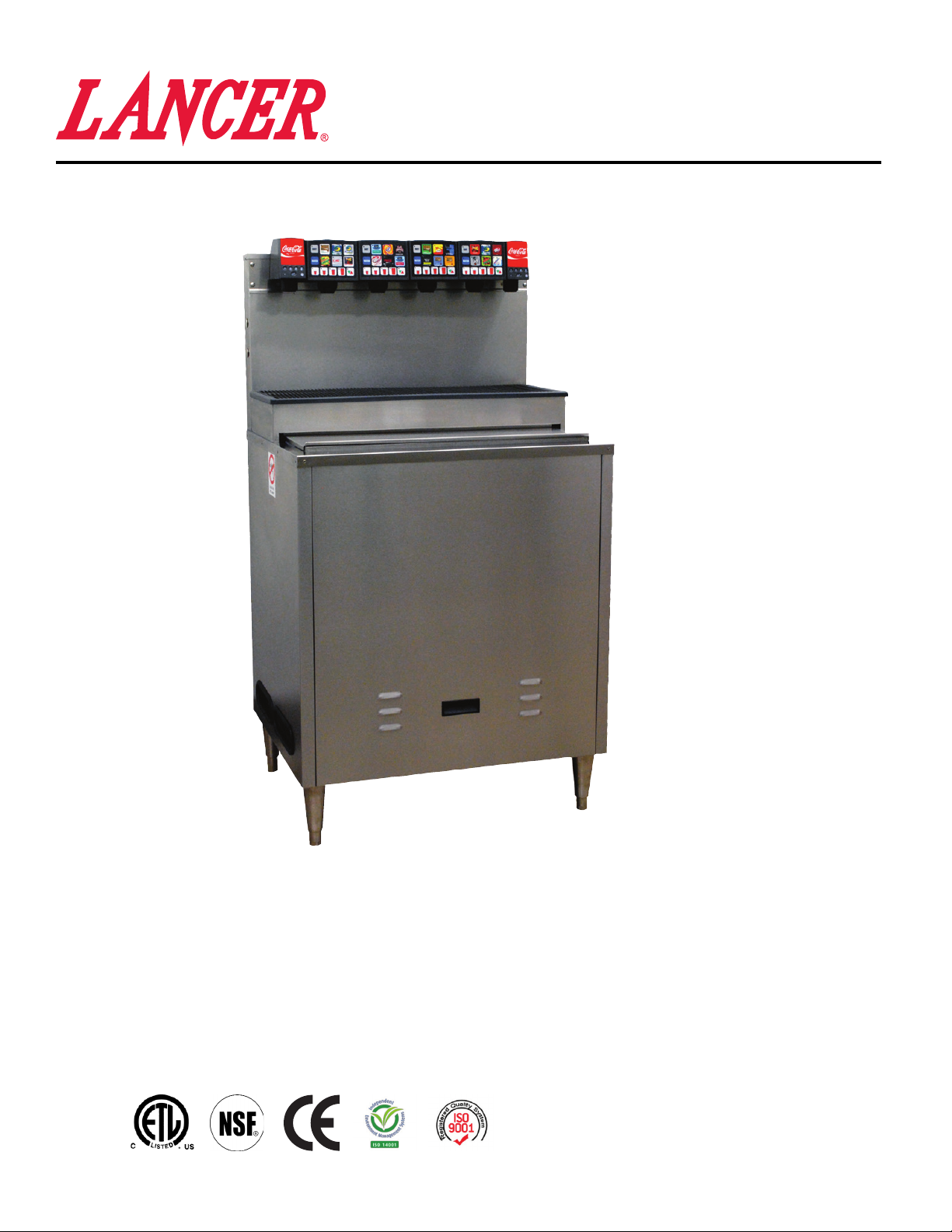
ICE COOLED DISPENSER SERIES 23308
Operation Manual
PN: 28-0752/03
23300
Lancer Corp.
6655 Lancer Blvd.
San Antonio, Texas 78219
800-729-1500
Technical Support/Warranty: 800-729-1550
custserv@lancercorp.com
lancercorp.com
Manual PN: 28-0752/03
FEBRUARY 2013
FOR QUALIFIED INSTALLER ONLY
“Lancer” is the registered trademark of Lancer © 2014 by Lancer, all rights reserved.
Page 2

ABOUT THIS MANUAL
This booklet is an integral and essential part of the product and should be handed over to the operator after the installation and preserved for any further consultation that may be necessary. Please read carefully the guidelines and warnings contained herein as they are intended to provide the user with essential information for the continued safe use
and maintenance of the product. In addition, it provides GUIDANCE ONLY to the user on the correct services and site
location of the unit.
The installation and relocation, if necessary, of this product must be carried out by qualied personnel with up-to-date
safety and hygiene knowledge and practical experience, in accordance with current regulations.
TABLE OF CONTENTS
SPECIFICATIONS...............................................................................................................................................3
PRE-INTALLATION CHECKLIST.......................................................................................................................4
WARNINGS/CAUTIONS..................................................................................................................................5-8
1. INSTALLATION............................................................................................................................................8
1.1 UNPACKING.......................................................................................................................................8
1.2 WATER SUPPLY.................................................................................................................................8
1.3 CARBONATOR SUPPLY.....................................................................................................................9
1.4 ELECTRIC SUPPLY............................................................................................................................9
1.5 CONNECTION OF THE EQUIPMENT................................................................................................9
1.6 START UP......................................................................................................................................9-10
1.7 ADJUSTING WATER FLOW FOR LEV.............................................................................................10
1.8 ADJUSTING WATER TO SYRUP RATIO (BRIX) FOR LEV.............................................................10
2. MVU OPERATION......................................................................................................................................11
2.1 MVU PLUMBING DIAGRAM - MAKING CONNECTIONS TO THE MVU.........................................11
2.2 SYSTEM START UP..........................................................................................................................11
2.3 PROGRAM THE MULTI VALVE UNIT (MVU)..............................................................................11-13
2.4 SET MVU FOR FLAVOR SHOTS.................................................................................................13-14
2.5 VIRTUAL BRAND PROGRAMMING.................................................................................................14
2.6 PROGRAM BRANDS FOR SOLD-OUT............................................................................................15
2.7 FLOW RATE CHECK........................................................................................................................16
2.8 RATIO PROCESS.............................................................................................................................17
2.9 PORTION CONTROL PROGRAMMING (MVU) (NO TOP-OFF).................................................17-18
2.10 PORTION CONTROL PROGRAMMING WITH TOP OFF (MVU)....................................................19
2.11 SHOT SIZE PROGRAMMING...........................................................................................................20
2.12 DISPENSER OPERATION................................................................................................................21
2.13 FINAL ASSEMBLY.............................................................................................................................21
3. RECOMMENDED SERVICE AND MAINTENANCE..................................................................................22
3.1 SCHEDULED.....................................................................................................................................22
3.2 CLEANING AND SANITIZING SYSTEMS.........................................................................................22
3.3 CLEANING AND SANITIZING BAG-IN-BOX (BIB) SYSTEMS.........................................................23
3.4 DAILY CLEANING - VALVES............................................................................................................23
3.5 MONTHLY CLEANING - ICE BIN COMPARTMENT ON ALL ICE CHESTS.....................................24
4. TROUBLESHOOTING...........................................................................................................................24-25
5. DISPENSER DISPOSAL............................................................................................................................25
6. ILLUSTRATIONS, PARTS LISTINGS, AND WIRING DIAGRAMS............................................................26
6.1 ICD SERIES 23308 FREESTANDING..........................................................................................26-27
6.2 ICD SERIES 23308 FREESTANDING TOWER ASSEMBLY........................................................28-29
6.3 NOZZLE SUB-ASSEMBLY................................................................................................................30
6.4 NOZZLE HYBRID MULTI-FLAVOR...................................................................................................30
6.5 VALVE ASSEMBLY 2-PACK, MVU....................................................................................................31
6.6 BODY FLOW CONTROL 2-PACK, MVU...........................................................................................31
6.7 BODY ASSEMBLY SOLENOID 2-PACK, MVU............................................................................32-33
6.8 CVM WATER VALVE ASSEMBLY 4.5...............................................................................................34
6.9 WIRING DIAGRAM...........................................................................................................................35
6.10 MVU..................................................................................................................................................36
6.11 MVU CONTROL BOARD..................................................................................................................37
6.12 POWER SUPPLY.........................................................................................................................38-39
Page 3
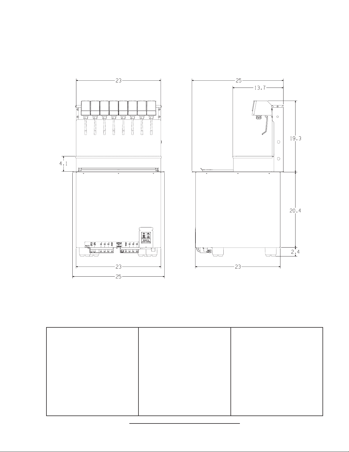
BEV ICD SERIES 23308 SPECIFICATIONS
DIMENSIONS
Width: 25 inches (635 mm)
Depth: 25 inches (635 mm)
Height: 39.7 inches (1008.38 mm)
ELECTRICAL
Dispenser: 24 VAC/ 6 Amps
Input: 115 VAC/ 12 Amps
Receptacle: 115 VAC/ 10 Amps
Output: 24 VAC/ 75 VA
This unit emits a sound pressure level below 70 dB
WEIGHT
Shipping: 296 lbs (134 kg)
Without ice: 253 lbs (115 kg)
With ice: 365 lbs (165 kg)
ICE
Capacity: 100 lbs (45 kg)
FITTINGS
Soda water inlet: 3/8” barb
Brand syrup inlets: 3/8” barb
3
PLAIN WATER SUPPLY
Min owing pressure:
20 PSI (0.138 MPA)
Max owing pressure:
50 PSI (0.345 MPA)
CARBON DIOXIDE (CO2)
Min pressure:
90 PSIG (0.621 MPA)
Max pressure:
110 PSIG (0.758 MPA)
Page 4
PRE-INSTALLATION CHECKLIST
BEFORE GETTING STARTED
Each unit is tested under operating conditions and is thoroughly inspected before
shipment. At the time of shipment, the carrier accepts responsibility for the unit. Upon
receiving the unit, carefully inspect the carton for visible damage. If damage exists, have
the carrier note the damage on the freight bill and le a claim with carrier. Responsibility for
damage to the dispenser lies with the carrier.
TOOLS REQUIRED
Oetiker Pliers Slotted Screwdriver
Tubing Cutters Phillips Screwdriver
Wrench Cordless Drill
POST MIX ACCESSORIES
CO2 Regulator Set CO2 Supply
Beverage Tubing Oetiker Clamps/Fittings
Water Booster Water Regulator
Precision Cutters (if removing/replacing carbonator tank)
BIB SYSTEM
BIB Rack BIB Regulator Set
BIB Syrup Boxes
BIB Connectors - ensure you have the correct connectors for syrup lineup.
CONSIDER LOCATION OF THE FOLLOWING PRIOR TO INSTALL
Water supply lines Drain
Is the countertop level? Heating and air conditioning ducts
Grounded electrical outlet.
Enough space to install the dispenser. Include space for a top-mounted ice machine, if necessary.
Does the top-mounted ice machine have a minimum clearance on all sides?
Located away from direct sunlight or overhead lighting.
Can the countertop support the weight of the dispenser? Be sure to include the weight of an ice
machine (if necessary) plus the weight of the ice.
This unit is not suitable for use in an area where a water jet could be used.
4
Page 5

! !
WARNING/ADVERTENCIA/AVERTISSEMENT
! The dispenser is for indoor use only. This unit is not a toy. Children should not be supervised not to play with
appliance. It should not be used by children or inrm persons without supervision. This appliance is not intended
for use by persons (including children) with reduced physical, sensory or mental capabilities, or lack of experience
and knowledge, unless they have been given supervision or instruction concerning use of the appliance by a person
responsible for their safety. Cleaning and user maintenance shall not be performed by children without supervision.
This unit is not designed to dispense dairy products. The min/max ambient operating temperature for the dispenser is
40°F to 90°F (4°C to 32°C). Do not operate unit below minimum ambient operation conditions. Should freezing occur,
cease operation of the unit and contact authorized service technician. Service, cleaning and sanitizing should be
accomplished only by trained personnel. Applicable safety precautions must be observed. Instruction w!arnings on
the product being used must be followed.
! El dispensador sólo debe usarse en interiores. Esta unidad no es un juguete. Los niños deben ser supervisados
para no jugar con aparato. No la deben usar niños ni personas discapacitadas sin supervisión. Esta unidad no está
destinada al uso por parte de personas (incluso niños) con capacidad física, sensorial o mental reducida, o sin
experiencia y conocimientos sucientes, a menos que una persona responsable de su seguridad les haya dado
supervisión o capacitación en el uso de la unidad. Limpieza y mantenimiento de usuario no deberá ser realizada por
los niños sin supervisión. Esta unidad no ha sido diseñada para suministrar productos lácteos. La temperatura
ambiente operativa mínima / máxima para el dispensador es de 40°F a 90°F (4°C a 32°C). No opere la unidad
debajo de las condiciones de funcionamiento ambientales mínimos. En caso de congelación se produce, cesar la
operación de la unidad y el contacto técnico de servicio autorizado. Servicio de limpieza y desinfección deben
llevarse a cabo solamente por personal capacitado. Es necesario tomar medidas de seguridad aplicables.
Advertencias de las instrucciones sobre el producto utilizado se deben seguir.
! Le distributeur est destiné à un usage à l’intérieur seulement. Cet appareil n’est pas un jouet. Les enfants doivent
être surveillés an de ne pas jouer avec l’appareil. Il ne devrait pas être utilisé par des enfants ou des personnes
inrmes sans surveillance. Cet appareil n’est pas destiné à un usage par des personnes (y compris les enfants)
ayant des capacités physiques, sensorielles ou mentales réduites, ou manquant d’expérience et de connaissances,
à moins qu’elles obtiennent de la surveillance ou des instructions au sujet de l’utilisation de l’appareil de la part d’une
personne chargée de leur sécurité. Nettoyage et entretien de l’utilisateur ne doivent pas être effectués par des
enfants sans surveillance. Cet appareil n’est pas conçu pour distribuer des produits laitiers. La température de
service ambiante minimum/maximum pour le distributeur est de 40°F à 90°F (4°C à 32°C). Ne pas utiliser l’appareil
dans des conditions de performance environnementale minimale. En cas de gel, cesser l’exploitation de l’unité
et contactez un technicien agréé. Nettoyage et désinfection doivent être effectuées uniquement par du personnel
qualié. Vous devez prendre des mesures de sécurité. Avertissements instructions sur le produit utilisé doivent être
respectées.
5
Page 6
!
This unit has been factory sanitized per Lancer specications.
Listed below are six critical elements which will aid in a successful installation.
1. Fill water bath until water overows from tank overow tube.
2. The carbonator pump motor must be disconnected from the power supply prior to connection to water supply for
initial build up of ice bank. Failure to do so will result in automatic shut off of carbonator (see item 6 below) or damage
to the pump.
3. If this dispenser is installed in an area that is susceptible to ±10% variation of the nominal line voltage, consider
installing a surge protector or similar protection device.
4. There is a ve (5) minute delay which prevents the compressor and condenser fan from starting until the delay
has lapsed. If electrical current is interrupted, there is always a ve (5) minute delay before the compressor starts.
5. Supply Water Pressure: Minimum - 20 PSI (0.138 MPA); Maximum - 50 PSI (0.345 MPA); If pressure is over 50
PSIG (0.345 MPA), a water pressure regulator must be used.
6. On units with the built in water regulator, the regulator must be removed if inlet water pressure is less than 20
PSIG. (0.138 MPA)
DISPENSER INSTALLATION HIGHLIGHTS
!
!
Esta unidad ha sido saneada en fabrica por las especicaciones de Lancer.
A continuacion se relacionan 6 puntos importantes para una connecta instalacion.
1. Llene el bano-Maria hasta que el agua se desborde sobre el tubo que controla la derrama del tanque.
2. El motor de la bomba del carbonatador debe desconectarse electricamente antes de conectar el suministro de
agua para la formacion inicial del banco de hielo. De no hacerse esto resultaria en un bloqueo automatico del
carbonatador (ver abajo el punto 6) o en danos a la bomba.
3. Si la unidad va a ser instalada en un area en la que puedan darse variaciones de voltage de + 6 - 10% de su
valor nominal, se debe considerar la conveniencia de instalar un estabilizador de corriente o sistema de proteccion
similar.
4. Hay una demora de 5 minutos que evita que el compresor y el abanico del condensador arranquen hasta pasado
ese tiempo. Si hay algun corte en la corriente electrica siempre se producira esa demora de 5 minutos antes de
arrancar el compresor.
5. Presión de suministro del agua de red: Minimo 20 PSI (0.138 MPA); Maximo 50 PSI (0.345 MPA). En unidades
sin regulador de presión incorporado, si la presión del agua es superior a 50 PSIG (0.345 MPA) se debe usar un
regulador de presión.
6. En unidades con regulador de presión incorporado, el regulador debe der eliminado cuando la presión de entrada
de agua sea inferior a 20 PSIG (0.138 MPA).
!
REGLES DE SECURITE POUR L’NSTALLATION DU DISTRIBUTEUR DE SODAS
PUNTOS IMPORTANTES EN LA UNIDAD DISPENSADORA
!
!
La proprètè da cet ensamable est assurè à I’usine sulvant les spècications èmis par Lancer .
Il est essentiel de respecter les 6 points suivants pour l’installation de l’appareil:
1. Remplir le bain-Maire jusqu’a ce que l’eau dèborde par le tuyau de trop-plein du rèservoir.
2. Le moteur de la pompe du carbonateur doit etre dèbranchè de l’alimentation èlectrique avant l’arrivèe de l’eau
pour la formation initiale de la glace. Oublier ou nègliger cette opèration provoquera l’arret automatique du
carbonateur (voir le point 6 cidessous) ou causera des dommages à la pompe.
3. Si le distributeur es installè dans une zone ou la tension èlectrique nominale est susceptible de variations de (+)
10%, il est conseillè d’installer un appaeil de protection contre les sautes de courant.
4. Un d’lai de 5 minutes empeche le compresseur et la ventilation du condesateur de se mettre en marche avant
que ce lees de temps ne se soit ècoulè. Lorsque le courant èlectrique es interrompu, il y a toujours un dèlai de 5
minutes avant que le presseur ne se mette en.
5. Pression de l’eau: Minimum 20 PSI (0.138 MPA); Maximo 50 PSI (0.345 MPA). Sur les unitès qui n’ont pas de
règulateur de pression d’eau incorprè, si la pression d’H2O est supèrieure à 50 PSIG (0.345 MPA), un règulateur de
pression d’eau doit etre utilsisè.
6. Sur les unitès avec règulateur d’eau incorporè, le règulateur doit etre enlevè si la pression d’arrivve est inferièure
à 20 PSIG (0.138 MPA)
6
Page 7
ELECTRICAL WARNING/ADVERTENCIA ELÉCTRICA/
F F
AVERTISSEMENT ÉLECTRIQUE
F Check the dispenser serial number plate for correct electrical requirements of unit. Do not plug into a wall
electrical outlet unless the current shown on the serial number plate agrees with local current available. Follow
all local electrical codes when making connections. Each dispenser must have a separate electrical circuit. Do not
use extension cords with this unit. Do not ‘gang’ together with other electrical devices on the same outlet. The
keyswitch does not disable the line voltage to the transformer primary. Always disconnect electrical power to the unit
to prevent personal injury before attempting any internal maintenance. The resettable breaker switch should not
be used as a substitute for unplugging the dispenser from the power source to service the unit. Only qualied person-
nel should service internal components of electrical control housing. Make sure that all water lines are tight
and units are dry before making any electrical connections!
F Verique la placa con el número de serie del dispensador, donde encontrará los requisitos eléctricos correctos
de la unidad. No enchufe la unidad en un tomacorriente de pared a menos que la corriente indicada en la placa con
el número de serie concuerde con la corriente local disponible. Al hacer las conexiones, respete todos los códi- gos
eléctricos locales. Cada dispensador debe tener un circuito eléctrico independiente. No use extensiones con esta
unidad. No la conecte junto con otros dispositivos eléctricos al mismo tomacorriente. El interruptor de llave no corta
el voltaje de línea al transformador primario desconecte siempre la alimentación eléctrica a la unidad para evitar
lesiones personales antes de tratar de realizar tareas de mantenimiento. El disyuntor de sobrecarga reseteable no se debe usar como sustituto para desenchufar el dispensador de la fuente de alimentación para realizar
tareas de servicio de la unidad. El servicio de los componentes internos de la caja de control eléctrico debe conarse
exclusivamente a personal calicado. Asegúrese de que todas las líneas de agua estén ajustadas y las unidades
estén secas antes de hacer conexiones eléctricas.
F Examinez la plaque de numéro de série du distributeur pour connaître les bonnes exigences en matière
d’électricité pour l’appareil. Ne le branchez pas à une prise électrique murale à moins que le courant indiqué sur la
plaque de numéro de série corresponde au courant local disponible. Respectez tous les codes électriques locaux
lorsque vous faites des connexions. Chaque distributrice doit avoir un circuit électrique séparé. N’utilisez pas
de cordons prolongateurs avec cet appareil. Ne pas le brancher avec d’autres appareils électriques sur la même
prise. L’interrupteur à clé ne coupe pas la tension secteur au transformateur primaire. Débranchez toujours le courant
électrique à l’appareil, an de prévenir des blessures, avant de faire un entretien interne quelconque. Le disjoncteur
réarmable ne devrait pas être utilisé au lieu de débrancher le distributeur de la source d’alimentation en électricité
pour faire de l’entretien/une réparation de l’appareil. Seul le personnel qualié devrait faire l’entretien/la réparation
des composants internes dans le logement des commandes électriques. Assurez-vous que toutes les conduites
d’eau sont étanches et que les appareils sont secs avant de faire des connexions électriques!
CO2/CARBON DIOXIDE /El ANHÍDRIDO CARBÓNICO/
5 5
DIOXYDE DE CARBONE
5 Carbon Dioxide (CO2) is a colorless, noncombustible gas with a light pungent odor. High percentages of CO2 may
displace oxygen in the blood. Prolonged exposure to CO2 can be harmful. Personnel exposed to high concentrations
of CO2 gas will experience tremors which are followed by a loss of consciousness and suffocation. If a CO2 gas leak
is suspected, immediately ventilate the contaminated area before attempting to repair the leak. Strict attention must
be observed in the prevention of CO2 gas leaks in the entire CO2 and soft drink system.
5 El anhídrido carbónico (CO2) es un gas incoloro, no combustible, con un olor pungente ligero. Altos porcentajes
de CO2 en la sangre pueden desplazar el oxígeno en la sangre. La exposición prolongada al CO2 puede ser nociva.
El personal expuesto a concentraciones altas de CO2 sufre temblores seguidos de la pérdida de la consciencia y
sofocación. Si se sospecha que existe una pérdida de CO2, ventile el área contaminada antes de tratar de reparar
la pérdida. Hay que prestar suma atención para evitar pérdidas de CO2 en todo el sistema de CO2 y de bebidas
gaseosas.
5 Le dioxyde de carbone (CO2) est plus lourd que l’air et déplace l'oxygène. Le CO2 est un gaz incolore et incom-
bustible, ayant une odeur un peu âcre. Des concentrations fortes de CO2 peuvent déplacer l'oxygène dans le sang.
Une exposition prolongée au CO2 peut être nocive. Le personnel exposé à de fortes concentrations de CO2 gazeux
éprouvera des tremblements, suivis rapidement d'une perte de conscience et de suffocation. On doit faire très attention de prévenir les fuites de CO2 gazeux dans le système entier de CO2 et de boisson gazeuse. Si on suspecte qu'il
y a une fuite de CO2 gazeux, aérez le secteur contaminé immédiatement avant d'essayer de réparer la fuite.
7
Page 8

! !
WATER NOTICE/AGUA AVISO/ PRÉAVIS DE L’EAU
! Provide an adequate potable water supply. Water pipe connections and xtures directly connected to a potable
water supply must be sized, installed, and maintained according to federal, state, and local laws. The water
supply line must be at least a 3/8 inches (9.525 mm) pipe with a minimum of 20 PSI (0.138 MPA) line pressure, but
not exceeding a maximum of 50 PSI (0.345 MPA). Water pressure exceeding 50 PSI (0.345 MPA) must be reduced
to 20 PSI (0.138 MPA) with the provided pressure regulator. Use a lter in the water line to avoid equipment damage
and beverage off-taste. Check the water lter periodically, as required by local conditions. The water supply must be
protected by means of an air gap, a backow prevention device (located upstream of the CO2 injection system) or
another approved method to comply with NSF standards. A leaking inlet water check valve will allow carbonated
water to ow back through the pump when it is shut off and contaminate the water supply. Ensure the backow prevention device complies with ASSE and local standards. It is the responsibility of the installer to ensure compliance.
! Proporcione un suministro adecuado de agua potable. La línea de suministro de agua debe ser de una tubería de
por lo menos 3/8 pulgadas (9.525 mm) con una presión de línea mínima de 20 PSI (0.138 MPA) , pero sin superar
el máximo de 50 PSI (0.345 MPA). La presión de agua que supere los 50 PSI (0.345 MPA) se debe reducir a 20 PSI
(0.138 MPA) con un regulador de presión. Use un ltro en la línea de agua para evitar daños al equipo y cierto sabor
raro en las bebidas. Verique periódicamente el ltro de agua de acuerdo con las condiciones imperantes. El
suministro de agua debe estar protegido por una separación de aire, un dispositivo de prevención del contraujo
(situado antes del sistema de inyección de CO2) u otro método aprobado para cumplir las normas NSF. Si la válvula
de retención de entrada de agua tuviera pérdidas, permitiría el contraujo del agua carbonatada a través de la
bomba cuando se la detiene y contaminaría el suministro de agua. Asegúrese de que el dispositivo de prevención del
contraujo cumpla con las normas locales y de ASSE. Es responsabilidad del instalador cumplir con estos requisitos.
! Fournissez une alimentation en eau potable adéquate. Les connexions et les dispositifs de conduite d’eau
con- nectés directement à une alimentation en eau potable doivent être calibrés, installés et maintenus selon les lois
fédérales, provinciales et locales. La conduite d’alimentation en eau doit être un tuyau d’au moins 3/8 pouces (9.525
millimètres) avec une pression de ligne minimum de 20 LPC (0.138 MPA) , mais ne doit pas dépasser un maximum
de 50 LPC (0.345 MPA). Une pression d’eau de plus de 50 LPC (0.345 MPA) doit être réduite à 20 LPC (0.138
MPA) avec le régu- lateur de pression fourni. Utilisez un ltre dans la conduite d’eau pour éviter des dommages à
l’équipement et un goût des boissons qui n’est pas juste. Vériez le ltre à eau périodiquement, selon les exigences
des conditions locales. L’alimentation en eau doit être protégée au moyen d’un intervalle d’air, un disconnecteur
hydraulique (situé en amont du système d’injection de CO2) ou une autre méthode approuvée pour se conformer
aux normes de la NSF. Un clapet antiretour pour l’eau entrante qui fuie permettra à l’eau gazeuse de repasser par
la pompe quand elle est fermée et de contaminer l’alimentation en eau. Assurez-vous que le disjoncteur hydraulique
soit conforme aux normes de l’ASSE et locales. L’installateur est responsable d’assurer la conformité.
1. INSTALLATION
1.1 UNPACKING
A. The ice cooled dispenser is shipped in a corrugated shipping carton. Remove the corrugated
shipping carton from the unit.
B. Remove the parts from the ice compartment.
C. Inspect the unit and parts for concealed damage. If damage exists, notify delivering carrier and
le a claim.
NOTE: In order to ensure unit draingage and proper carbonation, it is necessary for the dispenser
to be level, front to back and side to side.
1.2 WATER SUPPLY
A. Provide an adequate potable water supply The water supply line must be at least a 1/2 inch
(12.7 mm) pipe. Water pressure exceeding 50 PSI (0.345 MPA) is regulated by a pressure
regulator on the pump deck. Water pressure below 20 PSI (0.138 MPA) will require a booster
pump.
B. Install a shut-off valve in the water line feeding the deck. If a separate water line is run for plain
water, ensure that it also has a shut-off valve.
CAUTION POURING COFFEE, TEA, AND LIKE SUBSTANCES INTO THE DRAIN CAN CAUSE CLOGGING.
PRECAUCIÓN VERTER EL CAFÉ, EL TÉ Y SUSTANCIAS COMO EN EL DESAGÜE PUEDE CAUSAR LA
OBSTRUCCIÓN.
!
ATTENTION VERSER LE CAFÉ, LE THÉ ET DES SUBSTANCES COMME DANS LE DRAIN PEUT CAUSER
L’OBSTRUCTION.
8
Page 9

1.3 CARBONATOR PUMP
The carbonator pump is equipped with a strainer on the inlet side. A water supply containing any
appreciable quantity of silt, ne sand, or other debris requires a lter ahead of the pump deck.
Clean the lter cartridge periodically, depending on the condition of the water. Failure to do so may
starve the pump of water, causing it to burn out, and voiding the warranty.
1.4 ELECTRICAL SUPPLY
Locate a standard 20 AMP, 115 VAC, 60 Hz single phase electrical power outlet with ground
connectors for the power supply and pump deck.
GROUNDING WARNING THE DISPENSER MUST BE PROPERLY ELECTRICALLY GROUNDED TO AVOID
SERIOUS INJURY OR FATAL ELECTRICAL SHOCK. THE POWER CORD HAS A THREE-PRONG GROUNDED
PLUG. IF A THREE-HOLE GROUNDED ELECTRICAL OUTLET IS NOT AVAILABLE, USE AN APPROVED METHOD TO
GROUND THE UNIT. FOLLOW ALL LOCAL ELECTRICAL CODES WHEN MAKING CONNECTIONS. EACH
DISPENSER MUST HAVE A SEPARATE ELECTRICAL CIRCUIT. DO NOT USE EXTENSION CORDS. DO NOT
CONNECT MULTIPLE ELECTRICAL DEVICES ON THE SAME OUTLET.
ADVERTENCIA, PUESTA A TIERRA ES NECESARIO PONER A TIERRA ELÉCTRICAMENTE EL
DISPENSADOR PARA EVITAR LESIONES GRAVES E INCLUSO ELECTROCHOQUES FATALES. EL CABLE DE
ALIMENTACIÓN TIENE UN ENCHUFE PUESTO A TIERRA DE 3 CLAVIJAS. SI NO SE DISPONE DE UN TOMA
ELÉCTRICO CONECTADO A TIERRA DE TRES AGUJEROS, USE UN MÉTODO APROBADO PARA PONER A TIERRA
LA UNIDAD. AL HACER LAS CONEXIONES, RESPETE TODOS LOS CÓDIGOS ELÉCTRICOS LOCALES. CADA
F
DISPENSADOR DEBE TENER UN CIRCUITO ELÉCTRICO INDEPENDIENTE. NO USE CABLES DE EXTENSIÓN. NO
CONECTE VARIOS DISPOSITIVOS ELÉCTRICOS AL MISMO TOMACORRIENTE.
EXIGENCES DE MISE À LA TERRE LA DISTRIBUTRICE DOIT ÊTRE MISE À LA TERRE ÉLECTRIQUEMENT
CORRECTEMENT POUR ÉVITER DES BLESSURES GRAVES OU UNE DÉCHARGE ÉLECTRIQUE MORTELLE. LE
CORDON D’ALIMENTATION A UNE FICHE À TROIS BRANCHES MISE À LA TERRE. SI AUCUNE PRISE DE
COURANT ÉLECTRIQUE À TROIS TROUS N’EST DISPONIBLE, UTILISEZ UNE MÉTHODE APPROUVÉE POUR
METTRE L’UNITÉ À LA TERRE. RESPECTEZ TOUS LES CODES ÉLECTRIQUES LOCAUX LORSQUE VOUS FAITES
DES CONNEXIONS. CHAQUE DISTRIBUTRICE DOIT AVOIR UN CIRCUIT ÉLECTRIQUE SÉPARÉ. N’UTILISEZ PAS
DE CORDONS PROLONGATEURS. NE BRANCHEZ PAS PLUSIEURS APPAREILS ÉLECTRIQUES À LA MÊME PRISE
DE COURANT.
1.5 CONNECTION OF THE EQUIPMENT
A. Position to CO2 gas tank in the desired location. Assemble the high pressure regulator to the
CO2 gas tank and run the jumper line to the low pressure regulator.
B. Attach the CO2 gas line to the carbonator by attaching the line from the high pressure regulator
to the CO2 inlet. The setting of the high pressure CO2 gas regulator should be 75 PSI. Position
the syrup pumps in the desired location. Attach the CO2 gas lines leading from the low
pressure regulator to these pumps.
C. Connect the syrup lines from the pumps to the appropriate inlets at the front of the unit. The
syrup inlets are identied at the bottom of the unit.
D. Position the pump deck under the counter or within 75 feet of the dispenser.
E. Connect the water inlet line to the pump. Complete the water line connection between the
pump and the water inlet to the carbonator at the bottom of the dispenser.
F. Provide a suitable drain in the plumbing system and attach the 3/4 inch (1.90 cm) diameter
schedule 40 PVC drains to it. The drip pan drainage outlet is located at the right rear of the unit.
G. The ice bin drainage outlet is located at the right front of the unit.
H. Two insulated exible drain lines are provided to accommodate the drain connections.
I. Be sure to place the ice trap in the drain outlet inside the ice bin before lling with ice. This
device holds the ice away from the drain outlet, allowing the ice water to drain properly.
J. Locate the power supply and remove from carton. Follow the enclosed instructions and mount
the power supply to the dispenser base frame behind the front panel.
K. Plug in the power supply to a standard 20 AMP, 115 VAC single phase outlet. The unit will
internally convert the 115 VAC to 24 VAC.
1.6 START UP
A. After all connections to water, CO2 gas, electrical power, and syrup pumps are made, check for
leaks.
B. Be sure the Bag-In-Box contains syrup.
C. Turn on water. Open the pressure relief valve on the carbonator tank by ipping up the valve
cap lever, and hold it open until water ows from the relief valve. Close (ip down) the relief
valve and turn on the CO2 gas.
D. To ll all lines with water, cycle the carbonator several times by operating the dispensing valves.
9
Page 10
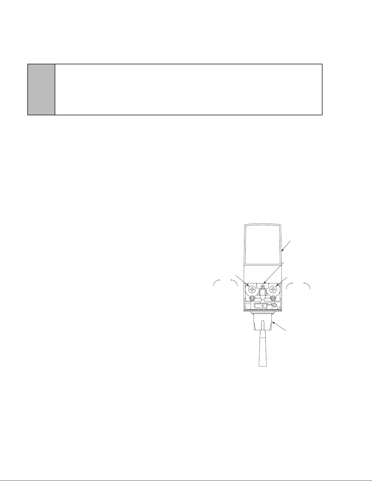
1.6 START UP (CONTINUED)
I.D. PANEL
(Shown in
open position)
COVER SCREW
NOZZLE (WITH
DIFFUSER INSIDE)
FLOW CONTROL
SYRUP
DecreaseIncrease
FLOW CONTROL
WATER
DecreaseIncrease
E. Ensure a good ow of plain water is established from each valve.
F. Turn on CO2 at source and ensure that the HP regulator is set at 75 PSIG.
G. Operate valves until unit gases out.
H. Plug in carbonator pump motor. Pump Deck will automatically start.
I. Activate carbonated water valves so that the carbonator pump cycles several times and a
J. A low pressure gas regulator controls the ow of syrup to each dispensing valve. Connect BIB
NOTE: The unit will cycle on for 5.5 seconds, shut down, and immmediately start again and run for
K. The dispenser bin should now be lled with ice cubes one inch below the level of the door
opening.
1.7 ADJUSTING WATER FLOW FOR LEV
The unit should have ice on the cold plate for a least one hour before you attempt to brix the valves.
A. Slide the ID panel up until the ow controls are
B. Remove the nozzle by twisting counterclockwise
and pulling down.
C. Remove the diffuser by pulling down.
D. Install Lancer yellow syrup separator (PN 54-0031)
in place of the nozzle.
E. Activate the dispensing valve to ll the separator
F. Hold a brix cup under the syrup separator and
G. To obtain the proper ow, use a screwdriver to
adjust the water ow control.
H. Repeat process for each valve.
1.8 ADJUSTING WATER TO SYRUP RATIO (BRIX) FOR LEV
A. Hold the brix cup under the syrup separator and
B. To obtain the proper ratio, use screwdriver to adjust
C. Remove syrup separator.
D. Install diffuser and nozzle.
E. Slide ID panel DOWN.
F. Repeat process for each valve.
5
WARNING DO NOT TURN ON THE CO2 SUPPLY AT THIS TIME. DO NOT OPERATE THE CARBONATOR PUMP
DECK WITH THE WATER SUPPLY TURNED OFF.
ADVERTENCIA NO CONECTE TODAVÍA LA ALIMENTACIÓN DE CO2. NO UTILICE LA PLATAFORMA DE LA
BOMBA DE CARBONATACIÓN CON EL SUMINISTRO DE AGUA APAGADO.
AVERTISSEMENT N’OUVREZ PAS L’ALIMENTATION EN CO2 À CE MOMENT. NE PAS FAIRE FONCTIONNER LA
PLATE-FORME DE POMPE DE CARBONATATION DE LA FOURNITURE DE L’EAU ÉTEINT.
good ow of carbonated water is established.
connectors to BIB’s. Set LP regulator to 65 PSIG. Activate all valves to purge air from the syrup
lines.
additional 5.5 second intervals until the water level reaches the probe.
The drink temperature should be no higher than 40 degrees F (4.4° C) when the ratio is set. This is
done after the unit has ice in the ice bin.
exposed (see Figure 1).
syrup tube.
dispense water and syrup into the cup for four
seconds. Divide the number of ounces (ml) of water
in the cup by four to determine the water ow rate
per second.
activate valve. Check ratio (brix).
syrup ow control.
Valve Adjustments
FIGURE 1
10
Page 11
2. MVU OPERATION
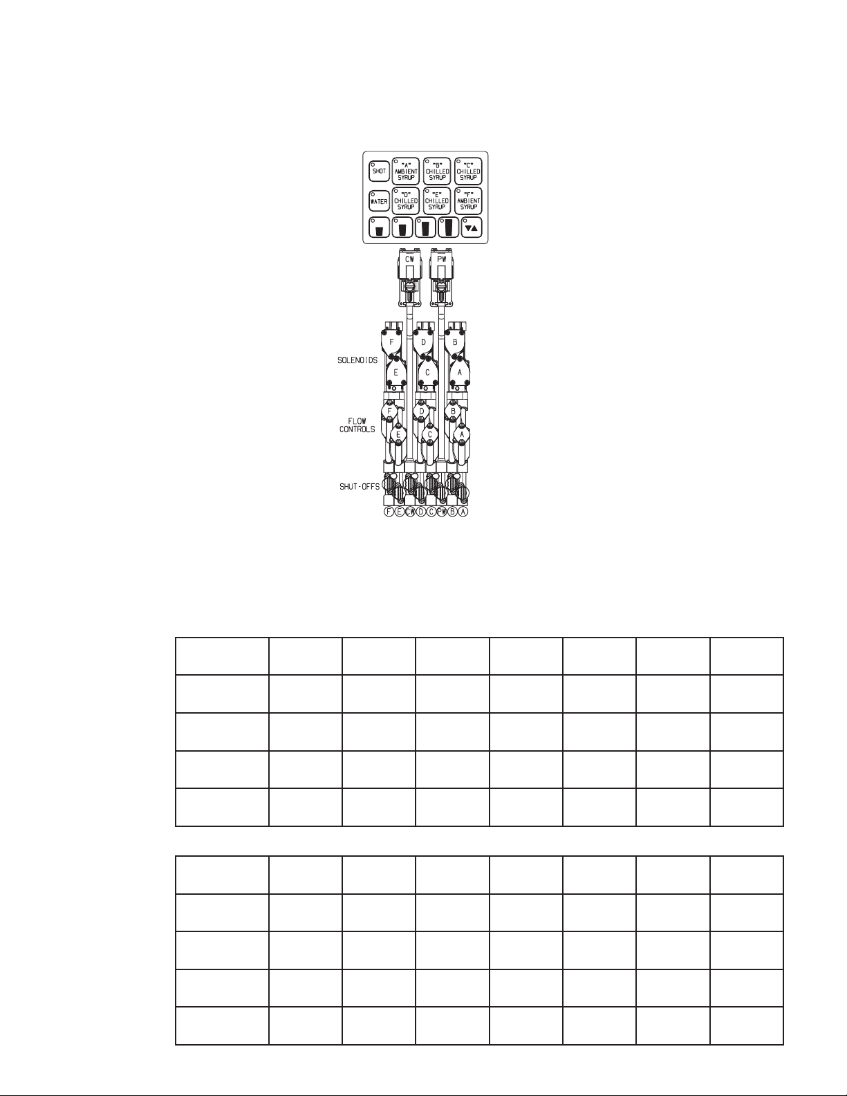
2.1 MVU PLUMBING DIAGRAM - MAKING CONNECTIONS TO THE MVU
A. Positions A and F are ambient syrups only. Remove the rear cover to make these syrup
connections. All other syrups and water are fed through the cold plate connections at the front
of the unit. Plumb according to the label on the unit.
Soda/Water
Flow Controls
and Solenoids
2.2 SYSTEM STARTUP
A. Pour several drinks from each MVU to prime for beverages.
B. Prime all avor shots.
2.3 PROGRAM THE MULTI VALVE UNIT (MVU)
All units are factory pre-set with the following:
MVU #1 (Right Side)
POSITION A B C D E F WATER/
Water Type Off Soda Soda Off Soda Off Soda
Shot On On On Off On On
Virtual
Brand
Sold Out On No Yes Yes Yes No No
MVU #2 (Right Corner)
POSITION A B C D E F WATER/
Water Type Plain
Shot On On On On On On
No No No B&A No No
Water
Plain
Water
Plain
Water
Plain
Water
SODA
SODA
Soda Off Water
Virtual
Brand
Sold Out On No No No No No No
No No No No No No
11
Page 12
2.3 PROGRAM THE MULTI VALVE UNIT (MVU) (CONTINUED)
MVU #3 (Left Center)
POSITION A B C D E F WATER/
Water Type Off Soda Soda Soda Off Plain
Shot Off On On On Off On
SODA
Water
Water
Virtual
Brand
Sold Out On No No No No No No
MVU #4 (Left Side)
POSITION A B C D E F WATER/
Water Type Off Soda Soda Soda Off Plain
Shot Off On On On Off On
Virtual
Brand
Sold Out On No No No No No No
*Virtual brands indirectly report a Sold Out from association with a sub-avor that has Sold Out
enabled. For example, in MVU #4 (above), if position B reports a Sold Out, position E will also
report a Sold Out because position B is a sub-avor of position E. In MVU #1, if position B reports a
Sold Out, position D will report a Sold Out because position D is a sub-avor of position B.
Set MVU Buttons as Carbonated, Non-Carbonated, or Flavor Shot Only.
The MVU can be programmed to serve soda or plain water beverages as well as a avor shots
from each of the beverage positions on the valve.
To enter the programming mode on the MVU and assign water type to each individual brand
(Carbonated or Non-carb):
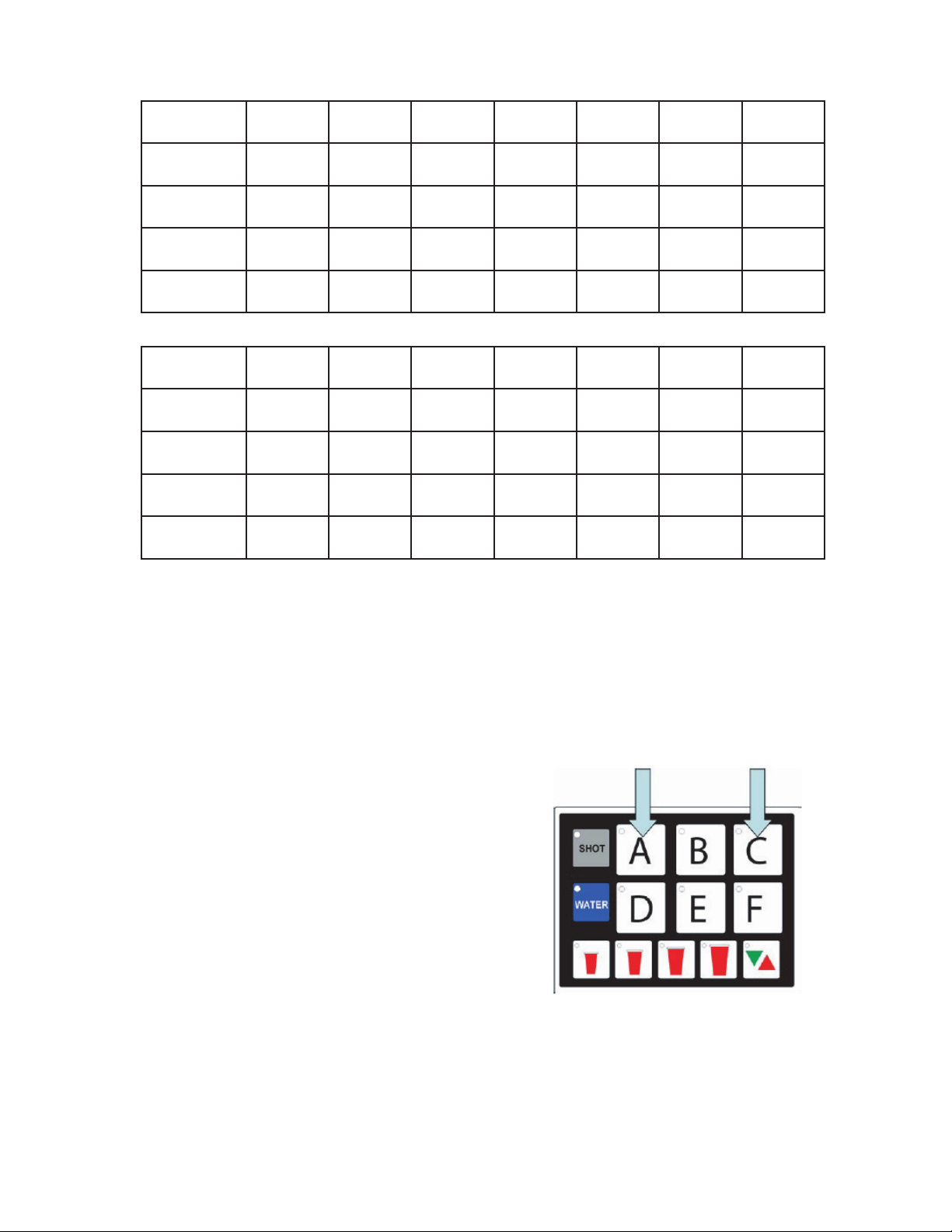
A. STEP 1
1. Press both A and C brand buttons at the same
time on the MVU panel for ve seconds.
2. The “Pour/Cancel” LED will illuminate. The
“SHOT” LED will blink one time.
3. Brands that are enabled for drinks will have
illuminated LED’s:
Lights on = non-carb
Lights ashing = carb
Lights ashing quickly = enabled for virtual
brands.
4. Buttons will not respond to key presses.
5. Lights off = no water (deactivated unless set for
shot).
No No No No No No
SODA
Water
Water
No No No No No No
12
Page 13

B. STEP 2
1. Press a Brand button to change that beverage
from “water off” to “plain water on”.
2. LED will illuminate and stay on for non-carb
beverages.
3. Press the same brand button again to switch
from non-carb to carb.
4. Press the button one more time to turn the water
off for that valve (if position is used for a avor
shot only).
C. STEP 3
1. Repeat this process for each brand.
D. STEP 4
1. Press the Pour/Cancel button to lock the changes in place and exit the programming
mode.
NOTE: The Program will save automatically in 60 seconds if no additional changes are made in
that time frame; however, you can exit any time within the 60 second window by pressing Pour/
Cancel. The changes you’ve made will be saved.
2.4 SET MVU FOR FLAVOR SHOTS
A. STEP 1
1. Press both A and C brand buttons (at the same
time) on the MVU panel for ve seconds to get
into programming mode.
B. STEP 2
1. Press the “Shot” button. The “Shot” button will
illuminate. Brands enabled for shots will be
illuminated.
C. STEP 3
1. Press the “Brand” button to turn the shot mode
for that brand on or off. The shot mode is “ON”
in the illustration.
13
Page 14

D. STEP 4
1. Press “Shot” again to return to “Drink Type Selection”
E. STEP 5
1. Press the Pour/Cancel Button to lock the changes in place and exit the programming mode.
NOTE: The program will save automatically in 60 seconds if no additional changes are made in
that time frame; however, you can exit any time within the 60 second window by pressing Pour/
Cancel. The changes you’ve made will be saved.
2.5 VIRTUAL BRAND PROGRAMMING
A. STEP 1
1. Press the D and F brand buttons simultaneously
for 5 seconds. Upon entering virtual brand
programming, avors already enabled for virtual
brand will blink quickly.
B. STEP 2
1. Select button to assign to virtual brand. LED
will illuminate.
C. STEP 3
1. Select host beverage. LED will blink slowly.
D. STEP 4
1. Select shot. LED will blink quickly.
E. STEP 5
1. Press the Pour/Cancel button to lock the
changes in place and exit the program mode.
NOTE: The program will save automatically in 60
seconds if no additional changes are made in that
time frame; however, you can exit any time within
the 60 second window by pressing Pour/Cancel.
The changes you’ve made will be saved.
14
Page 15

2.6 PROGRAMMING BRANDS FOR SOLD-OUT
The syrup inlet must be equipped with a sold out switch
and the harness must be connected to the respective
MVU control board at J6 or J7.
J6 = Sold Out Sensor 1
J7 = Sold Out Sensor 2
A maximum of 2 brands per MVU can be set for Sold
Out. If a virtual brand’s host brand is set for Sold Out,
the virtual brand will also be controlled by the Sold Out
switch.’
A. STEP 1
Press the C and F brand buttons simultaneously
for 5 seconds.
B. STEP 2
Select Sold Out Input 1. The LED will illuminate.
C. STEP 3
Select Sold Out Input 2. The LED will blink slowly.
D. STEP 4
Press the Pour/Cancel button to lock the changes
and exit the program mode.
NOTE: The program will save automatically in 60
seconds if no additional changes are made in that
time frame; however, you can exit any time within
the 60 second window by pressing Pour/Cancel.
The changes you’ve made will be saved.
15
Page 16

2.7 FLOW RATE CHECK
The Dispenser’s water ow rate can be checked/calibrated using the on board computer as a timer.
To check/adjust ow rate:
A. STEP 1: Remove splashguard and module cover to expose syrup ow controls and solenoids.
Remove tower cap to expose the soda and plain water ow controls.
All active brands should have their shutoffs in the open position as illustrated below.
CW = Carbonated Water (sparkling)
PW = Plain Water (still)
B. STEP 2
1. Press the A & B buttons for 5 seconds
simultaneously.
2. The Pour/Cancel button will illuminate and the
shot LED will blink 5 times.
C. STEP 3
1. Remove outer nozzle and insert syrup separator
(Lancer PN 82-3964/01). This is important to do
during ow rate check so you can determine if
the separator has been properly installed.
NOTE: Water will leak through to the syrup
chamber if not properly installed.
2. Place a ratio cup under the nozzle and press
a brand button. The brand’s water module will
open and pour for 4 seconds.
NOTE: Only water will pour during the ow
rate check.
3. Check for 15 oz of water in the ratio cup. If
above or below 15 oz, adjust the water
16
Page 17

2.8 RATIO PROCESS
A. STEP 1: Remove outer nozzle and insert MVU separator if not done on previous step.
B. STEP 2: Prime separator by running the valve.
C. STEP 3: Press and ll the ratio cup to the appropriate levels.
D. STEP 4: Check/adjust ratio on each brand. Use ow controls to adjust syrup.
2.9 PORTION CONTROL PROGRAMMING (MVU) (NO TOP-OFF)
A. STEP 1
1. Press the S and XL at the same time for ve seconds to enter the portion setting mode.
2. The Pour/Cancel light will illuminate and the shot light will blink two times.
B. STEP 2
Press the Brand button. The selected brand’s LED will illuminate.
Multiple brands can be programmed at the same time to pour the same amounts for each size
during this step. Do this by selecting several brand buttons; however, the rst button selected
will illuminate and only its beverage will pour. The other brands selected will ash slowly.
If multi-brand programming, do not set carbonated drinks and non-carbonated drinks at the
same time because carbonated drinks will foam.
NOTE: The LED will blink twice and turn off if the brand has been programmed as a avor shot
instead of a drink. You will need to reprogram the brand as a drink prior to setting the portion.
17
Page 18

2.9 PORTION CONTROL PROGRAMMING (MVU)
(NO TOP-OFF) (CONTINUED)
C. STEP 3
1. Fill cup 1/2 full with ice and place it under the
nozzle, push and hold a drink “size” button until
the cup is full.
2. Once the pour is completed, the LED will blink
slowly to indicate that a new pour duration has
been programmed for that key.
D. STEP 4
Repeat this step for each of the other size cups.
E. STEP 5
1. Select other brands and repeat these steps for each of them.
2. Press the “Pour/Cancel” button to save programming.
NOTE: The program will save automatically in 60 seconds if no additional changes are made in
that time frame; however, you can exit any time within the 60 second window by pressing Pour/
Cancel. The changes you’ve made will be saved.
18
Page 19

2.10 PORTION CONTROL PROGRAMMING WITH TOP-OFF (MVU)
A. STEP 1
1. Press the S, L, and Pour/Cancel buttons at the same time for two seconds to enter portion
setting mode.
2. The Pour/Cancel light will illuminate and the shot light will blink three times.
B. STEP 2
1. Press the brand button.
2. The selected brand’s LED will illuminate.
3. Multiple brands can be programmed at the same time to pour the same amounts for each
size during this step. Do this by selecting several brand buttons; however, the rst button
selected will illuminate and only its beverage will pour. The other brands selected will ash
slowly.
4. If multi-brand programming, do not set carbonated drinks and non-carbonated drinks at the
same time because carbonated drinks tend to pour faster.
C. STEP 3
Fill cup 1/2 full with ice.
D. STEP 4
1. Place cup under the nozzle, push and hold a
drink “size” button until the cup is full.
2. Once the pour is completed, the LED will
blink fast to indicate Settle Time programming
mode.
3. If the duration is more than 40 seconds, the
dispense function is stopped and the portion
E. STEP 5
After beverage settles, press the Size button again
to top off the drink. If the settle time is more than
fteen seconds, the auto top-off times are cleared
for all selected avors.
F. STEP 6
Repeat steps 2-5 for additional brands and cup
sizes.
G. STEP 7
1. Press Pour/Cancel button to save the portions
and exit programming mode.
2. If no button is pressed in 60 seconds, the
system will exit program mode and save the
current programming.
3. The Pour/Cancel will blink until the program
is saved.
19
Page 20

2.11 SHOT SIZE PROGRAMMING
Flavor shot portions can be adjusted using the MVU touchpad and a graduated cylinder. To adjust
avor shots:
A. STEP 1
1. While in Portion Control Programming, press the Shot button.
2. Pressing the Shot button again will exit Shot Size Programming.
B. STEP 2
Press a “Brand” button. The brand button will illuminate.
NOTE: If brand is not enabled for shot mode, the LED light on that brand will blink twice and
turn off.
C. STEP 3
1. Place a graduated cylinder under the nozzle.
2. Press and hold the XL portion button until the
portion size is achieved. Target is 30 ml (1 0z) of
syrup for an XL portion for most customers.
3. The XLRG LED will blink slowly to indicate that
a new shot duration has been programmed.
NOTE: The other size buttons are proportioned
automatically based on the amount poured in XL
mode:
Small = 25% of XL portion
Medium = 50% of XL portion
Large = 75% of XL portion
D. STEP 4
Repeat steps 2 and 3 for each of the other brands.
E. STEP 5
Press Pour/Cancel to save the settings.
NOTE: The Program will save automatically in 60
seconds if no additional changes are made in that
time frame; however, you can exit any time within
the 60 seconds window by pressing Pour/Cancel.
The changes you’ve made will be saved.
20
Page 21

2.12 DISPENSER OPERATION
CREW SERVE BEVERAGE DISPENSING
FLAVOR SHOT DISPENSING - PORTION CONTROL
A. STEP 1
Place cup under MVU nozzle.
B. STEP 2
Press the “Shot” button. The “Shot” LCD will stay
illuminated (active) for 10 seconds.
C. STEP 3
Select Brand Button. Brand will stay illuminated
for up to ten seconds. Touch brand again to
deactivate.
D. STEP 4
1. Select portion control size button to begin dispensing avor shot.
2. Press “Pour/Cancel” to stop dispense mode.
BEVERAGE DISPENSING - PORTION CONTROL
A. STEP 1
Press the brand button. Button stays active for 10
seconds or until another brand is pressed.
B. STEP 2
1. Press a portion control size button. Beverage
will pour.
2. Press the Pour/Cancel to stop pour prior to
complete dispense.
BEVERAGES - MANUAL DISPENSE
A. STEP 1
Press the brand button. Button stays active for ten
seconds or until another brand is pressed.
B. STEP 2
1. Press and hold the pour/cancel button. The
beverage continues to pour until the button is
released.
2. The selection will stay in memory for ten
seconds.
3. The valve can pour for a maximum of thirty
seconds.
2.13 FINAL ASSEMBLY
A. Reinstall the front cover plate.
B. Reinstall drip tray, splash plate and cup rest. System is ready for operation.
21
Page 22

3. RECOMMENDED SERVICE AND MAINTENANCE
3.1 SCHEDULED
Daily – Section 3.4
Monthly – Section 3.5 .
Periodic Sanitizing - Sections 3.2 and 3.3
As Needed - Keep exterior surfaces of dispenser (including drip tray and cup rest) clean with a
damp cloth.
3.2 CLEANING AND SANITIZING SYSTEMS
A. General Information
Lancer equipment (new or reconditioned) is shipped from the factory cleaned and sanitized
according to NSF guidelines. The operator of the equipment must provide continuous
maintenance as required by this manual and state and local health department guidelines to
maintain proper operation and sanitization.
NOTE: The cleaning and sanitizing procedures below pertain to the Lancer equipment
identied by this manual. If other equipment is being cleaned, follow the guidelines established
for that equipment.
Cleaning and sanitizing should be accomplished only by trained personnel. Use sanitary gloves
during cleaning and sanitizing operations. Observe all safety precautions. Follow instruction
warnings on the cleaning product.
CAUTION TO AVOID CONTAMINATION, DO NOT DISCONNECT WATER LINES WHEN CLEANING AND
SANITIZING SYRUP LINES.
PRECAUCIÓN PARA EVITAR LA CONTAMINACIÓN, NO DESCONECTE LAS LÍNEAS DE AGUA AL LIMPIAR Y
DESINFECTAR LÍNEAS DE JARABE.
!
ATTENTION POUR ÉVITER TOUTE CONTAMINATION, NE PAS DÉCONNECTER LES CONDUITES D’EAU LORS
DU NETTOYAGE ET L’ASSAINISSEMENT DES CHAÎNES DE SIROP.
B. Recommended Cleaning Solution
Cleaning solutions (for example, Ivory Liquid, Calgon, etc.) mixed with clean, potable water at a
temperature of 90 to 110 degrees Fahrenheit should be used to clean equipment. The mixture
ratio, using Ivory Liquid, is one ounce of cleanser to two gallons of water. A minimum of four
gallons of cleaning mixture should be prepared.
NOTE: Extended lengths of product lines may require that an additional volume of solution be
prepared.
Any equivalent cleanser may be used as long as it provides a caustic-based, non-perfumed,
easily-rinsed mixture containing at least two percent sodium hydroxide (NaOH).
C. Recommended Sanitizing Solution
Sanitizing solutions should be prepared according to the manufacturer’s written
recommendations and safety guidelines. Follow manufacturer’s requirements so that the
solution provides 200 parts per million (PPM) chlorine at a temperature of 90 degrees F to 120
degrees F. Prepare a minimum of four gallons of sanitizing solution.
NOTE: Extended lengths of product lines may require that an additional volume of solution be
prepared.
Any sanitizing solution may be used as long as it is prepared according to the manufacturer’s
written recommendations and safety guidelines, and provides 200 parts per million (PPM)
chlorine.
22
Page 23

3.3 CLEANING AND SANITIZING BAG-IN-BOX (BIB) SYSTEMS
A. Disconnect syrup quick disconnect coupling from syrup packages and connect coupling to a
bag valve removed from an empty Bag-in-Box package.
B. Place end of syrup inlet line, with bag valve attached, in a clean container lled with clean,
potable, roomtemperature water.
C. Place waste container under applicable dispensing valve. Activate valve until water is
dispensed. Flush and rinse line and ttings for a minimum of 60 seconds to remove all traces of
residual product.
NOTE: Extended lengths of product lines may require additional time for ushing and rinsing lines.
D. Prepare cleaning solution as described in Section 3.2 above. Place end of syrup inlet line in
container lled with cleaning solution.
E. Place waste container under applicable dispensing valve. Activate valve and draw cleaning
solution through lines for a minimum of sixty seconds. This will ensure line is ushed and lled
with cleaning solution. Allow line to stand for at least thirty minutes.
F. Place end of syrup inlet line in a clean container lled with clean, potable water at a
temperature of 90 to 110 degrees F.
G. Place waste container under applicable dispensing valve. Activate valve to ush and rinse line
and ttings for a minimum of sixty seconds to remove all traces of cleaning solution. Continue
rinsing until testing with phenolpthalein shows that the rinse water is free of residual detergent.
H. Prepare sanitizing solution as described in Section 3.2 above. Place end of syrup inlet line in
container lled with sanitizing solution which has been prepared.
I. Activate valve and draw sanitizing solution through line for a minimum of sixty seconds. This
will ensure line is ushed and lled with sanitizing solution. Allow line to stand for at least
fteen minutes.
J. Remove bag valve from quick disconnect coupling and reconnect syrup inlet line to syrup
package. Ready unit for operation.
CAUTION FOLLOWING SANITIZATION, RINSE WITH END-USE PRODUCT UNTIL THERE IS NO AFTERTASTE. DO
NOT USE A FRESH WATER RINSE. THIS IS A NSF REQUIREMENT. RESIDUAL SANITIZING SOLUTION LEFT IN THE
SYSTEM CREATES A HEALTH HAZARD.
PRECAUCIÓN DESPUÉS DE LA ESTERILIZACIÓN, ENJUAGUE CON EL PRODUCTO FINAL HASTA QUE
ELIMINAR EL SABOR QUE QUEDA. NO ENJUAGUE CON AGUA FRESCA. ÉSTA ES UNA EXIGENCIA DE NSF. SI
!
K. Draw drinks and rell lines with end product to ush sanitizing solution from the dispenser.
NOTE: A fresh water rinse cannot follow sanitization of equipment. Purge only with the end use
L. Test dispenser in the normal manner for proper operation. Taste dispensed product to ensure
M. Repeat cleaning, rinsing, and sanitizing procedures for each valve circuit.
3.4 DAILY CLEANING - VALVES
Valves may be cleaned and sanitized (see preparation in Section 3.2) in the same manner.
A. Remove cover and disconnect power so the valve will not be activated during the cleaning
procedure. Remove nozzle and diffuser. Wash these parts in cleaning solution, then immerse
B. Visually inspect around nozzle area for syrup residue. This area may be cleaned with warm
C. Wearing sanitary gloves, remove, drain and air dry the nozzle and diffuser.
D. Wearing sanitary gloves, replace diffuser, twist nozzle in place.
E. Connect power and replace cover. Valve is ready for operation.
QUEDA SOLUCIÓN DE ESTERILIZACIÓN EN EL SISTEMA, GENERA UN PELIGRO PARA LA SALUD.
ATTENTION DÉFENSE DE RINCER L’OUTIL À L’EAU FRAICHE IMMÉDIATEMENT APRÈS UN TRAITEMENT
SEPTIQUE.EN CAS DE APRÈS-GOÛT, NE PURGER AVEC LE PRODUIT FINAL UNE EXIGENCE NSF.
product. This is an NSF requirement.
there is no offtaste. If off-taste is found, ush syrup system again.
them in a bath of sanitizing solution for 15 minutes.
water and cloth or with the nozzle brush supplied. Wipe off dispensing lever.
23
Page 24

3.5 MONTHLY CLEANING - ICE BIN COMPARTMENT ON ALL ICE CHESTS
A. Clean and sanitize the ice bin compartment of the dispenser thoroughly at least once every
month. Use the following procedure:
B. Prepare cleaning solution and sanitizing solution described in Section 3.2.
C. Using the cleaning solution and a clean soft cloth, wash down the sides of the ice bin and the
surface of the aluminum casting.
D. Using clean, potable water, thoroughly rinse away the cleaning solution from the sides and
surface of the casting.
E. Using plastic sanitary gloves, soak a white cotton gauze cleaning rag in the sanitizing solution
and wipe all surfaces in the ice compartment.
NOTE: A fresh water rinse cannot follow sanitization of equipment. Purge only with the end-use
product. This is an NSF requirement.
F. Sanitizing of the ice compartment is complete. Rell with ice.
4. TROUBLESHOOTING
TROUBLE CAUSE REMEDY
4.1 No carbonation. A. Carbonator motor not running.
A. Check power supply to see if plugged
in. Check if LED light is blinking. If so,
reset by unplugging and re-plugging
power supply.
B. Absence of CO2 gas.
C. Gas only from valves.
D. Carbonator tank air bound.
E. CO2 gas pressure below 75 PSI.
F. Carbonator motor running
continuously.
G. Water pump not moving water.
H. No ice on cold plate.
4.2 Noisy carbonator pump. A. Insufcient water supply or water leak
allowing air to be pulled into pump.
B. Replace with full tank of CO2 gas.
C. Check for power failure. Check fuses.
Clean strainer on pump.
D. Relieve gas pressure in tank by
ipping up relief valve until water spurts
out.
E. Reset high pressure CO2 gas
regulator to 75 PSI. Change CO2 tank if
required.
F. Inspect check valve for blockage.
Check carbonator control. Check
carbonator pump for efciency.
G. Replace water pump if necessary.
H. Fill bin with ice.
A. Provide adequate water supply.
Ensure strainer is clean.
B. Loose pump coupling.
4.3 Valves inoperable. A. Loss of power.
B. Faulty bin switch.
B. Tighten set screw on pump coupling.
A. Check power supply to see if plugged
in. Check transformer circuit breaker.
Check main power circuit breaker. Check
keylock switch on side of tower to ensure
it is in the “ON” position.
B. Ensure proper connection.
24
Page 25

TROUBLE CAUSE REMEDY
4.4 Pump deck LED blinking 4 blinks per
second.
A. No water to pump. A. Ensure water supply is on, carbonator
pump motor is connected, and probe is
not damaged. Reset by unplugging
and re-plugging power supply.
4.5 Pump deck LED blinking 1 blink per
second.
5. DISPENSER DISPOSAL
To prevent possible harm to the environment from improper disposal, recycle the unit
by locating an authorized recycler or contact the retailer where the product was pur
chased. Comply with local regulations regarding disposal of the refrigerant and
insulation.
A. Short in probe.
B. Short in harness.
C. Crossed wires in harness or probe
plug.
A. Replace probe.
B. Replace harness.
C. Correct wiring (see CCNA Bulletin
Serv 256).
25
Page 26

6. ILLUSTRATIONS, PARTS LISTINGS, AND WIRING DIAGRAMS
6.1 ICD SERIES 23308 FREESTANDING
26
Page 27

6.1 ICD SERIES 23308 FREESTANDING (CONTINUED)
Item Part No. Description
1 30-10260 Panel, Back, F/S, Sonic, 30x23
2 05-2455 Handle, Flush Pull, Snap Fit
3 50-0503 Isolator Pad, Panel, F/S, 3023
4 30-10299 Panel, Front, 3023FS
5 52-3075 Probe Assy, 2.5 Cast in Carb, KO
6 81-0663 Leg, 4Pcs, Adjst, 6” Tall, SS-Foot
7 82-3644 Pwr Supply, Dual, 120-24V, 155VA
8 04-0558 Screw, 10-32 x .375 LG, PHP, Roloc
9 30-10227 Brkt, Elect Hsg, Pwr Sply, Sonic
10 15-0200 Edge Guard, Vinyl, Spl, PL, IC
11 06-3142 Decal, “DO NOT DRILL”
12 12-0097 Switch, Key Lock, Maintain, Spade
13 82-4016 Kit, Dbl Bin Lid Switch, Cld Crb
14 23-0862 Drain Assy, Wire, IC
15 04-0148 Screw, 10-32 x .250, THD, SL, MS, SS
16 51-6280 Weldment Assy, Front Cover, MVU
17 05-2467 Coupler, Drip Tray Drain, IC
18 05-2728 Drip Tray, Sonic, 30”, CIC
19 23-1001/01 Cup Rest, Wire, 3023
20 30-5926 Splash Plate, 3023
21 30-10302 Lid, Sliding, 30x23, Cld Crb
22 19-0353/02 LEV, 4.5 PC
23 23-1483 Tower Assy, Lft, Sonic, 30x23
24 82-3981-1 Twr Assy, Ctr Module, Variety Sta
25 82-3981 Twr Assy, Ctr Module, Variety Sta
26 82-3981-2 Twr Assy, Ctr Module, Variety Sta
27 23-1482 Tower Assy, Rgt, Sonic, 30x23
28 30-10384 Cap, Tower, 30x23, Sonic
29 07-0360 Plug, Hole, 7/8” Dia, SS
30 51-6284 Tower Assy, 2-PC, Sonic, 30x23
31 04-1537 Scr, 1/4-20x.500, HH, H/W, MS, SS, P
32 30-9971 Cover, Probe, Front Wrapper
33 04-0236 Scr, 10-24x.375, PHD, PH, MS, SS
34 54-0066 Relief Valve Assy, Plastic
35 04-1566 Scr, 8-18x3/8, PHD, PH, AB
36 42-0142 Cong Assy, FMD, 2A/4C, MVU
37 52-3218 Harness, Extension, 75ft, Probe
27
Page 28

6.2 ICD SERIES 23308 FREESTANDING TOWER ASSEMBLY
A
B
PW
C
D
CW
E
F
FRONT
PLUMBING DIAGRAM
A
14
B
15
WATER
12
C
16
14
15
A A A A
B B B B
16
17
C C C C
D D D D
DETAIL A
HARNESS CONNECTIONS
E E E E
F F F F
J7
J6
29
17
18
11
19
18
19
1 2
ON
J5
MOVE #2 SWITCH
TO THE ON POSITION
12
J11
32
SHOWN AS REFERENCE ONLY
22
11
23
21
20
10
1
24
5
2
28
7
USE TIE WRAPS
TO TIE DOWN
INSULATION
ONTO TUBES
6
7
9
36
29
26
35
34
33
13
27
3
6
25
6
31
8
4
3
28
30
Page 29

6.2 ICD SERIES 23308 FREESTANDING TOWER ASSEMBLY (CONTINUED)
Item Part No. Description
1 02-0089 O-Ring, 2-012, 97-0999
2 05-2775 Retainer, Slnd Outlet Frg, M
3 04-0236 Scr, 10-24x.375, PHD, PH, MS, S
4 04-0267/02 Scr, 8-16x.5, PLSTI, HHSW/W, S
5 04-1574 Scr, 8-32x1.25, PH, PH/SL, RL
6 04-0470 Scr, 6-19x.500, PHD, PH/SL, PL
7 04-0481 Scr, 8-32x1.125, PH, PH/SL, RL
8 05-2682 Bracket, Cover Mount, MVU
9 05-2687/01 Plate, Nozzle, MVU
10 05-2751 Retainer, Water Outlet, MVU
11 06-0111 Label, Soda Soda
12 06-0112 Label, Water Water
13 06-3077 Overlay, Button Board, MVU
14 06-3127 Label, “A A A A”
15 06-3128 Label, “B B B B”
16 06-3129 Label, “C C C C”
17 06-3130 Label, “D D D D”
18 06-3131 Label, “E E E E”
19 06-3132 Label, “F F F F”
20 17-0622-2 Body Assy, Shutoff, 2-Pack
21 19-0470 Vlv Assy, 2-Pack, SY/SY 4.5
- 17-0624-1 Body Assy, Flow Control, 4.5 Syrup
- 17-0645 Body Assy, Solenoid, 2-Pack, 4.5
22 19-0463 Vlv Assy, CVM, Water 4.5
23 30-10272 Structure, Tower, MVU, Sonic
24 82-4014 Uptube Assy, Insulated, MVU
25 49-0325 Nozzle, Subassy, Sonic, MVU
26 52-3160 Panel Assy, ID, MVU
27 52-3169 HRNS Assy, Solenoid, MVU/BUN
28 54-0464 Cover Assy, MVU
29 64-5011/02 PCB Assy, Controller, MVU
30 50-0506 Foam, Insul, Outlt Fitting
31 50-0507 Foam, Insul, FC, Sonic
32 50-0508 Foam, Insul, Side Tube
33 50-0509 Foam, Insul, Nozzle, Sonic
34 11-0190 Tie, Wire, WIT-60R
35 52-3208 Harness, MVU/Sense Wire
36 52-3211 Harness, Sold Out Switch
29
Page 30

6.3 NOZZLE SUB-ASSEMBLY
Item Part No. Description
1 01-0012 Adaptor, 1/4 Barb x Dole
2 02-0005 O-Ring, 2-010, 97-0999
3 07-0446 CLMP, STPLS,
OETKR16700988, 13/32
4 07-0433 CLP, STPLS, OTKR,
16700993, 1/2
5 08-0523/01 MVU, TUBE, FORMED
6 08-0029 TUBING, INNERBRD,
.250ID x .4
7 54-0481 Nozzle, Hybrid Multi Flavor
8 05-2766 Lock, Hose, HMFN
9 54-0473 Outlet Assy, Water, MVU 4.5
10 02-0089 O-Ring, 2-012, 97-0999
6.4 NOZZLE, HYBRID MULTI-FLAVOR
Item Part No. Description
1 54-0480 Injector Assy, Syrup, HFMN, 4
A 02-0005 O-Ring
B 05-2747 Body Injector
C 05-2696 Injector Cap
2 05-2746/01 Nozzle, Body, Inner, HMFN
3 05-2745 Nozzle, Body, Main, HMFN
4 04-0269 Scr, 8-16x.375, PHD, PH/SL, PL
5 02-0232 O-Ring, 2-030, 97-0999
6 03-0449 Plate, Nozzle, Locking, HMFN
7 05-2693 Cap, Inlet, Water HMFN
8 05-2699 Outer Nozzle, Overmold, HMFN
A
B
C
30
Page 31

6.5 VALVE ASSEMBLY 2-PACK, MVU
1
Item Part No. Description
1 17-0624-1 Body Assy, FC, 4.5, Syrup
2 17-0645 Body Assy, Solenoid, 2-Pack, 4.5
6.6 BODY FLOW CONTROL 2-PACK, MVU
2
Item Part No. Description
1 05-2671 Body, Flow Control, 2-Pack
2 03-0088/02 Retainer, Flow Control
3 82-0527/01 Plug Adjustment Assy, Syrup, Wht
4 81-0382 Sleeve, Syrup/Soda, 4.5 oz, Valve
5 81-0383 Piston, Syrup, 4.5 oz, Valve
6 02-0132 O-Ring, 2-113, 97-0999
7 03-0169 Spring, Syrup Flow Control, LEV
8 04-0267/02 Scr, 8-16x.5, PLSTI, HHSW/W, SS
9 06-2519-29 Label, Barcode, 2-PK S/S, 4.5
31
Page 32

6.7 BODY ASSEMBLY SOLENOID 2-PACK, MVU
1
16
14
2X
15
8X
2
3
11
4
5
6
2X
7
8
32
FRONT VIEW
(RETAINER PLATES AND
9
10
12
17
SCREWS REMOVED)
13
6X
Page 33

6.7 BODY ASSEMBLY SOLENOID 2-PACK, MVU (CONTINUED)
Item Part No. Description
1 05-2670 Body, Solenoid, 2-Pack
2 02-0005 O-Ring, 2-010, 97-0999
3 05-2732 Seat, MVU
4 04-0060/01 Washer, Solenoid, VV
5 03-0180/02 Spring, Core, VV
6 23-1488 Core Assy, Molded Seal, VV
7 12-0364/04-01 Coil Assy, LFCV
8 02-0538 O-Ring, 5-212, 97-0999
9 10-0430/05 Plug Nut, Solenoid, LFCV, 430C
10 81-0515/01 Bonnet Subassy, SOL, LFCV
11 02-0109 O-Ring, 2-114, 97-0999
12 30-7843/02 Rtnr, Sol, Flow Cont, VLV Assy
13 04-0270 Scr, 6-19x.910, PHD, PH/SL, PLT
14 10-0848 Ftg, Couple, .5 Dole x .5 Dole
15 02-0003 O-Ring, 2-011, 97-0999
16 06-2519-09 Label, Kit Label, Generic
17 30-10364 Brkt, Sol, Flow Cont, Vlv Assy
33
Page 34

6.8 CVM WATER VALVE ASSEMBLY 4.5
2
10
10
20
9
6
5
14
15
17
19
18
7
1
11
3
13
4
12
8
16
Item Part No. Description
1 02-0109 O-RING, 2-114,97-0999
2 82-0528 PLUG ADJUST ASSY, WHITE/GREEN
3 02-0132 O-RING, 2-113, 97-0999
4 02-0005 O-RING, 2-010, 97-0999
5 02-0538 O-RING, 5-212, 97-0999
6 03-0088/02 RETAINER, FLOW CONTROL
7 03-0171 SPRING, SODA FLOW CONT, LEV
8 03-0180/02 SPRING, CORE, VV
9 03-0450 RETAINER, SOLENOID, CVM
10 04-0267/02 SCR, 8-16X.5, PLSTI, HHSW/W, S
11 04-0600/01 WASHER, SOLENOID, VV
12 05-2732 SEAT, MVU
13 06-2519-26 LABEL, BARCODE, CVM WATER, 4.5
14 10-0430/05 PLUG NUT, SOLENOID, LFCV, 430
15 12-0364/04-01 COIL ASSY, LFCV
16 23-1442 CORE ASSY, MOLDED SEAL
17 54-0467 VALVE BODY SONIC WELD ASSY
18 81-0384 PISTON, WATER, 4.5OZ, VALVE
19 81-0382 SLEEVE, SYRUP/SODA, 4.5 OZ, VA
20 81-0515/01 BONNET SUBASSY, SOL, LFCV
34
Page 35

6.9 WIRING DIAGRAM
2
1
3
6
7
5
4
Item Part No. Description
1 52-0931/01 Harness Assy, SOS, Main
2 52-3210 Harness, Main, Right Side, MVU
3 52-3205 Harness, Main, Left Side, MVU
4 52-3207 Harness, Wire Assy, Jumper
5 52-3206 Harness Assy, Keyswitch
6 52-3211 Harness Assy, SOS, Connection
7 52-3208 Harness Assy, MVU/Sense Wire
35
Page 36

6.10 MVU
36
Page 37

6.11 MVU CONTROL BOARD
37
Page 38

6.12 POWER SUPPLY
19
3
4
2
9
10
7
1
27
8
18
12
16
13
14
28
6
29
5
38
15
Page 39

6.12 POWER SUPPLY (CONTINUED)
Item Part No. Description
1 30-10225/01 Base, Elect Hsg, Power Supply
2 30-10226 Cover, Elect Hsg, Power Supply
3 52-3201 Outlet Assy, AC, Power Supply
4 52-3202/01 Harn, 24V Out, 115V In
5 52-3203 LED Assy, Power Indicator
6 52-3204 Lead, Black, Circuit Breaker
7 25-0094 Transformer, Toroidal, 115VA, 22VAC
8 04-1412/01 Scr, 1/4-20 x 2.00, HXHD
9 04-0033/01 Washer, Flat, 1/4
10 04-0032/01 Nut, Nylock, 1/4-20
12 04-0292 Scr, 6-32 x .438, PH, PH
13 04-0297 Nut, Hex, 8-32, KEPS
14 04-0558 Scr, 10-32 x .375, PH, PH
15 12-0419 Breaker, Circuit, 3.5A
16 12-0541 Terminal Block
18 13-0008 Strain Relief
19 52-3290 Pwr Cord Assy, Power Supply
27 06-3060 Label, Wiring Diagram, Power Supply
28 52-3239 Harness, 24V Out
29 13-0213 Strain Relief
39
Page 40

Lancer Corp.
800-729-1500
Technical Support/Warranty: 800-729-1550
custserv@lancercorp.com
lancercorp.com
 Loading...