

LAKOS PPS User Manual
Pump Protection Separators
Installation Guide
LAKOS Pump Protection Separators come in a variety of
sizes. They can be used with either turbine pumps or large
submersible pumps. They may be shipped in a variety of ways.
Most often, each unit is strapped onto a wooden skid. Before
installation, remove all labels, decals and shipping instructions
from each unit to avoid plugging the inlet slots. LAKOS Pump
Protection Separators are designed to continuously ush
separated particles back into the source water.
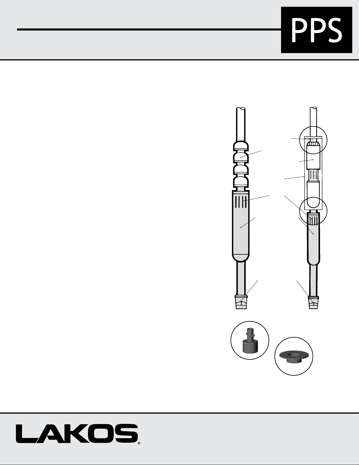
For Turbine pumps:
LAKOS Turbine Separators are manufactured with a standard
M.N.P.T. riser (note General Specications chart on next
page). Should this riser not match the connection to your
pump’s bowl assembly, you’ll need to arrange for the proper
connection (i.e. reducer, etc.). Lifting lugs are provided on the
riser of all models size “E” through “K” for ease of installation.
Connect the separator to the bowl assembly, then install
the apper valve as shown on page 3. At this point, you may
proceed with your customary routine for installing the pump.
FOR
TURBINE
PUMPS
Pump Riser
Pump Bowls
Submersible Pump
Pump Enclosure
Shell
Separator Inlet
Slots
LAKOS Separator
FOR
SUBMERSIBLE
PUMPS
For Submersible pumps:
To allow LAKOS Pump Protection Separators to remove sand
prior to the pump intake, the water must rst be directed
to rst pass through the separator. To achieve this with a
submersible pump, LAKOS provides a pump enclosure shell
or shell kit (see page 4). The submersible pump is positioned
within this shell and then attached directly to the separator
outlet. With the pump properly secured in the shell, the riser
is now attached directly to the column pipe. Installation may
now proceed as normal for submersible pumps.
Once installed, LAKOS Pump Protection Separators require
no routine maintenance. Should you ever need to pull your
pump, always take the opportunity to inspect the separator
and purge assembly.
Flexible Flapper
Valve
Closed when pump is in
operation. Opens when
pump shuts off or
when sand load pushes
the valve open.
Top with Shell Kit
Bottom with
Separator
Connection
Separators and Filtration Solutions
Page 1
Pump Protection Separators Installation Guide
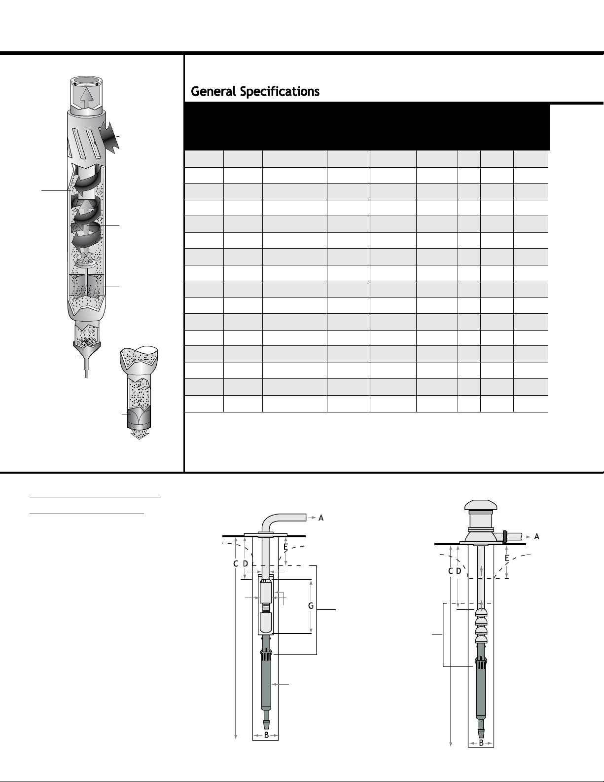
Sand is
centrifugally
separated from
water and tossed
to perimeter
of chamber.
Flapper Valve Closed
Sand accumulates
in separator.
Flapper Valve Open
Sand discharges
deep into well.
Sandy water is
drawn through
tangential inlet
slots into
separation
chamber.
Sand-free water
is drawn to
center of
separator and up
through vortex
outlet to pump’s
suction.
Sand particles
fall downward,
along perimeter,
to bottom
of separator.
143
141
168
219
219
219
270
270
273
273
324
324
356
356
406
406
Length With
Riser &
Flapper Valve
in
88-3/8
106
120-1/4
124
130
132-1/2
141-1/2
145-3/4
147
150-1/2
154
158
163
170
185
204
Minimum
Model
PPS-100-D
PPS-125-E
PPS-150-F
PPS-325-GSA
PPS-520-GGA
PPS-325-G
PPS-600-HSA
PPS-880-HHA
PPS-550-H
PPS-1290-ISA
PPS-825-I
PPS-1460-JSA
PPS-1010-J
PPS-1780-KSA
PPS-1640-K
PPS-2520-KKA
Head Loss: Typically, 9-14 feet (2.74-4.27m), except models with optional tail pipes, which will experience a notably greater head
loss. Consult factory for details.
Maximum Particle Size: 1/4 inch (6.3mm)
Maximum Particle Concentration: 1,000 ppm
*Optional tail pipe in place of the flapper valve
Well I.D.
in mm mmU.S. gpm m
152
6
178
7
203
8
248
9-3/4
248
9-3/4
273
10-3/4
305
12
305
12
337
13-1/4
337
13-1/4
387
15-1/4
387
15-1/4
438
17-1/4
438
17-1/4
489
19-1/4
489
19-1/4
Flow Range
100-175
125-250
150-325
325-520
520-710
325-650
600-910
880-1375
550-1110
1290-1700
825-1450
1460-2040
1010-1800
1780-2420
1640-2560
2520-3180
3
23-40
29-57
34-74
74-118
118-161
74-148
136-207
200-312
125-252
293-386
187-329
332-463
230-409
404-550
373-582
573-723
/ hr
Outside
Diameter
in
5-5/8
5-9/16
6-5/8
8-5/8
8-5/8
8-5/8
10-5/8
10-5/8
10-3/4
10-3/4
12-3/4
12-3/4
14
14
16
16
mm
2245
2692
3054
3150
3302
3366
3594
3702
3734
3823
3912
4013
4140
4318
4699
5182
Length of
Tail Pipe
meters
ft
20
6.1
20
6.1
20
6.1
40
12.2
40
12.2
20
6.1
60
18.3
60
18.3
20
6.1
60
18.3
20
6.1
60
18.3
20
6.1
60
18.3
20
6.1
60
18.3
Riser
Size
2-1/2 "
3"
4"
6"
6"
6"
8"
8"
8"
8"
8"
10"
10"
10"
10"
12"
Weight
lbs M.N.P.T.
93
142
220
191
213
267
281
315
390
393
454
492
526
575
703
754
Submergence
kg
42
64
100
87
97
121
128
143
177
178
206
223
239
261
319
342
Required
Minimum
ft meters
30
30
30
60
60
30
60
60
30
60
30
60
30
60
30
60
9.2
9.2
9.2
18.4
18.4
9.2
18.4
18.4
9.2
18.4
9.2
18.4
9.2
18.4
9.2
18.4
Required Information
Prior to Installation
(Actual Field Conditions)
A. Maximum and minimum
ow rate of pump
B. Minimum inside diameter
(I.D.) of well
C. Depth of well
D. Depth of pump setting
E. Pumping water level
F. Maximum diameter of
pump/motor
G. Overall length of pump
and motor
H. Pump’s riser size
Contact LAKOS so Worksheet LS-423 can be completed.
Page 2
For Submersible Pumps
H
F
Pump
Enclosure
Shell
LAKOS
Separator
For Turbine Pumps
IMPORTANT:
Separator models with
single-letter designations
(i.e. D, E, F, etc.) require a
minimum submergence of
30 ft (9.2m) below the
drawdown water level.
Models with three-letter
designations require 60 ft
(18.3m) submergence.
Minimum clearance below
separator’s purge discharge:
30 ft (9.2m)
 Loading...