


LAKOS SST & PRO II Installation and Operations Manual
SST & PRO II Media
Filtration Systems
Installation and Operation Instructions
THIS MANUAL TO BE LEFT WITH THE END-USER
LAKOS PRO II & SST Systems are available with an optional skid mount assembly. Consult factory for details.
TABLE OF CONTENTS
Recommended Accessories.................... |
Page 2 |
Introduction....................................................... |
3 |
Basics of Operation ......................................... |
4 |
General Specifications PRO II.......................... |
5 |
Materials of Construction PRO II...................... |
5 |
General Specifications SST ............................ |
6 |
Materials of Construction SST ........................ |
6 |
Media Sand Options ........................................ |
7 |
Site Preparations ............................................. |
7 |
Pre-Installation Checklist ................................. |
7 |
Filter System Installation ................................. |
8 |
Assembling The Components ......................... |
8 |
Automatic Controller Configuration .................. |
9 |
Start-Up Procedures ...................................... |
10 |
Periodic/Mid-Season Maintenance ................ |
11 |
Seasonal Shutdown Procedures .................. |
11 |
Backwash Repair Recommendations ............ |
12 |
Troubleshooting ............................................. |
14 |
APPENDIX |
|
Kits and Spare Parts Listing, LS-695 and LS-699 |
|
LS-906 (Rev. 2/12)
Page 1
LAKOS SST & PRO II Installation and Operations Manual
Before You Begin....
CAUTION: Water sources vary and may contain impurities that can adversely affect a filter system. Minerals, biological microbes and other impurities must be identified and addressed by each user on a case-by-case basis. Adhere to seasonal shutdown recommendations to minimize problems. Contact your irrigation system dealer for additional information and further recommendations.
CAUTION: It is common to inject chemicals and/or liquid fertilizers into a drip/micro irrigation system.
Such injection is recommended after the filter system to minimize potential deterioration and/or damage to the filter tanks and/or other filter system components.
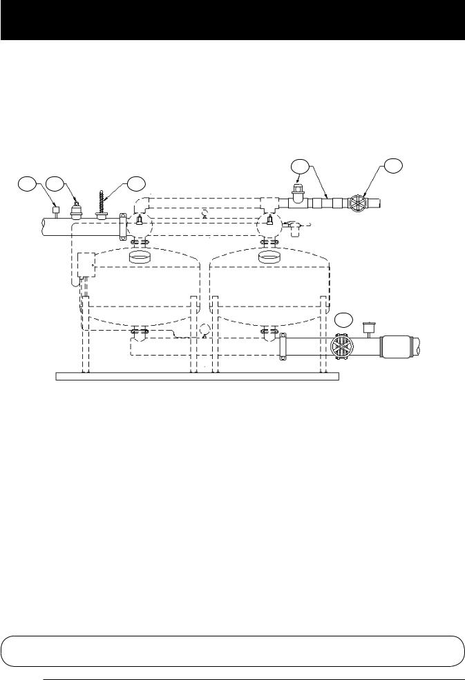
Recommended Accessories
4 |
5 |
1 |
2 |
3 |
6
The following items are NOT INCLUDED with your LAKOS SST or PRO II Filter System. Consider the need and use your judgement when adding to your system.
1.High pressure shut-off switch
Installed on inlet, pre-set at maximum operating pressure of the filter system.
2.Air vents
Should be installed at highest points in the manifolds to bleed trapped air from the system.
3.Pressure relief vents
These will protect the filter system from excess spikes in pressure or water hammer.
4.Backwash sightglass/view-tube (available as an option from LAKOS)
Provides visual verification that backwash is in progress and operating at proper flow rate.
5.Backwash line throttling valve
This valve helps ensure the proper backwash flow is maintained. See Start-Up Procedures, page 10.
6.Pressure-Sustaining valve
Either manual or automatic valve to ensure adequate flow during backwash. Restricts downstream flow to direct necessary flow/pressure for backwashing.
For Additional Kits and Spare Parts:
Refer to literature LS-695 and LS-699 for SST and PRO II Sand Media Kits
Page 2
LAKOS SST & PRO II Installation and Operations Manual
Introduction
LAKOS Systems are the industry standard for operating performance and efficiency. Please read this manual carefully to ensure the best performance possible for your system. This manual contains information regarding assembly, start-up, seasonal shut-down, maintenance and troubleshooting. Keep this document for future use and reference. Should you have any questions or concerns, contact your LAKOS representative for further assistance.
LAKOS Sand Media Filtration Systems are designed for use with drip/micro irrigation systems to keep unwanted particle matter out of the irrigation system. Media filtration is recommended when the contaminants are lightweight in nature, such as algae, organics, silt, etc. For heavy sand particles, which may not backwash during normal operation, consider a LAKOS Centrifugal Separator
as a pre-filter to prevent excess accumulation of sand particles on the sand media. (e.g. IHB Separator, BRS, to name two options)
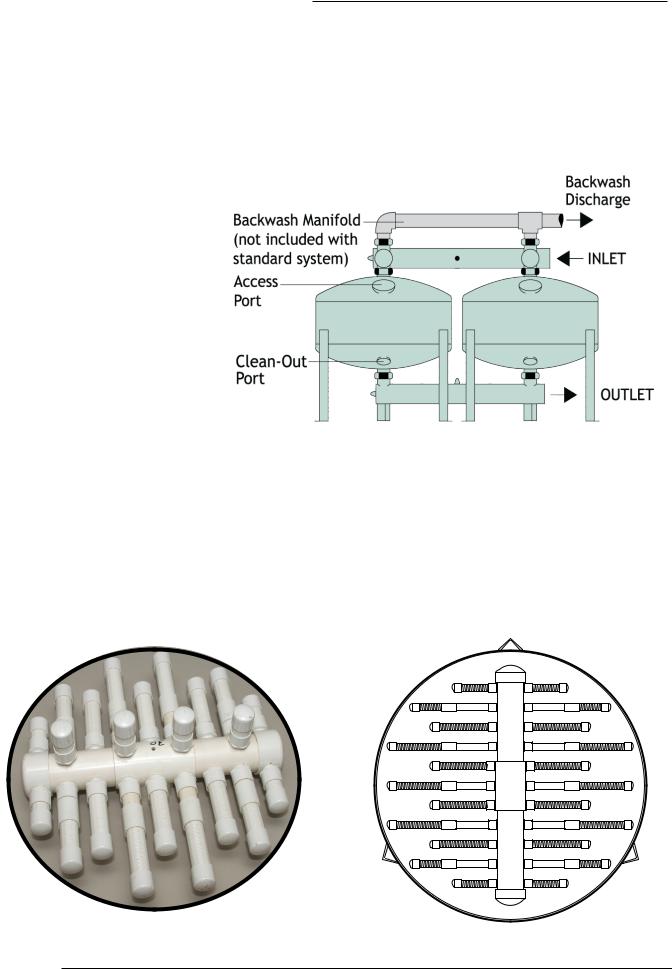
The exclusive LAKOS Underdrain only requires one grade of media sand. No need for a coarse gravel pack, since the LAKOS Underdrain is a full-coverage pattern, enabling backwash water to immediately flow upward from the underdrain to uniformly and completely flush the entire media bed depth and surface area.
LAKOS UNDERDRAIN
Page 3
LAKOS SST & PRO II Installation and Operations Manual
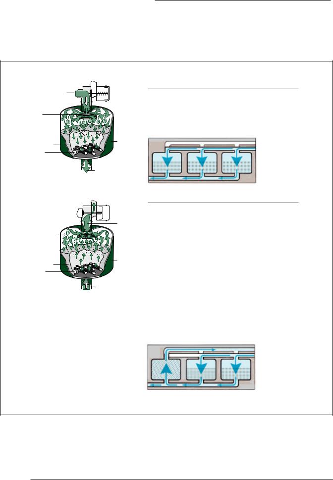
Basics of Operation
From water source |
ackwash |
(via manifold) |
alve |
Flowispersion Assembly
Filter Tank
edia Sand
LAKOS Lateral
nderdrain Assembly
To System
The Filtering Process
The filtering process engages the use of a specified sand media to trap foreign matter on the surface layer, allowing filtered water to percolate through the
sand media and LAKOS internal v-slotted lateral assembly, discharging at the bottom of each tank to the outlet manifold.
|
To ackwash |
|
isposal |
ontaminants |
|
suspended |
|
off media |
|
sand bed |
|
edia Sand |
Filter Tank |
|
|
LAKOS |
|
Lateral |
|
nderdrain |
|
Assembly |
ackwash Flow |
|
(from other |
|
filter tanks) |
The Backwash Cycle
The backwash cycle flushes trapped debris from the sand media and out of the filter tanks. Each tank in a LAKOS System is flushed individually for maximum agitation of the sand media. Triggered by pressure differential, by elapsed time or manually, each tank's backwash valve
is alternately activated into the backwash mode, which simultaneously interrupts inlet flow to that particular tank. Overall system pressure then directs partial system flow back into and through the tank's lateral assembly.
Flow continues for a prescribed period of time (typically one minute), suspending the foreign matter and carrying it out through the tank's top port (normal inlet) and out through the backwash valve and piping. The backwash valve then returns to its original position and restores the now "clean" filter tank to normal service.
NOTE: The LAKOS automatic controller provides a variable time delay between stations to avoid overlapping backwash cycles and maximize backwash efficiency.
Page 4

LAKOS SST & PRO II Installation and Operations Manual
PRO II General Specifications
Flow Range** |
System Manifold |
System Media |
Maximum Filter |
System |
Minimum |
Recommended |
Inlet/Outlet |
Sand |
Backwash Flow |
||||
Model* |
Grooved |
Requirement |
Tank Pressure |
Filtration Area |
Backwash |
Rate Per Tank |
|
Couplings |
|
|
|
Line Size |
|
U.S. gpm |
3 |
/hr. |
in. |
cm. |
lbs. |
kg |
psi |
bar |
ft |
2 |
m |
2 |
in. |
cm. |
U.S. |
m3/hr. |
m |
|
|
gpm |
|||||||||||||
|
|
|
4 |
10.2 |
|
|
|
|
4.8 |
0.45 |
3 |
7.6 |
36 |
8.2 |
||
|
|
|
4 |
10.2 |
|
|
|
|
7.2 |
0.67 |
3 |
7.6 |
36 |
8.2 |
||
|
|
|
4 |
10.2 |
|
|
|
|
10.8 |
1.00 |
3 |
7.6 |
81 |
18.4 |
||
|
|
|
4 |
10.2 |
|
|
|
|
16.2 |
1.50 |
3 |
7.6 |
81 |
18.4 |
||
|
|
|
6 |
15.2 |
|
|
|
|
25.1 |
2.33 |
4 |
10.2 |
188 |
42.7 |
||
|
|
|
6 |
15.2 |
|
|
|
|
37.7 |
3.50 |
4 |
10.2 |
188 |
42.7 |
||
|
|
|
8 |
20.3 |
|
|
|
|
50.2 |
4.66 |
4 |
10.2 |
188 |
42.7 |
||
|
|
|
10 |
25.4 |
|
|
|
|
62.8 |
5.83 |
4 |
10.2 |
188 |
42.7 |
||
|
|
|
10 |
25.4 |
|
|
|
|
75.4 |
7.00 |
4 |
10.2 |
188 |
42.7 |
||
|
|
|
10 |
25.4 |
|
|
|
|
87.9 |
8.17 |
4 |
10.2 |
188 |
42.7 |
||
|
|
|
10 |
25.4 |
|
|
|
|
100.4 |
9.33 |
4 |
10.2 |
188 |
42.7 |
||
|
|
|
12 |
30.5 |
|
|
|
|
125.6 |
11.67 |
4 |
10.2 |
188 |
42.7 |
||
*Model numbers identify individual tank size/diameter (first two numbers), inlet/outlet size (second two numbers) and number of tanks per system (last number).
**Flow range based on a filtration range of 15-25 U.S. gpm/ft2 (37-61 m3/hr/m2).
***NOTE: Minimum recommended operating pressure range for proper actuation of LAKOS Backwash Valve is 20 psi (1.4 bar).
The stated flow range is based on a filtration range of 15-25 gpm/ ft2. (37-61 m3/hr/m2).
Materials of Construction
Filter Tanks: A-36 carbon steel; 3-inch lower sand clean out port; 10 gauge thickness; powdercoated inside and outside.
Manifolds: Piping for 48-inch tanks is stainless steel, grooved-end connections. 14 gauge wall thickness. Piping for 21 & 32-inch tanks is schedule 80 PVC pipe. Couplings are ductile steel.
Backwash Valves: Cast steel body with epoxy coated internal/external. Rear-entry feature for inspection/replacement of plunger diaphragm. Stainless steel shaft & guide bushing (3-inch valve: PVC guide bushing). Stainless steel disc with vulcanized rubber to seal the backwash port.
Controller: Solid-state timing. Standard LAKOS Controller accommodates 12-volt DC or solar power, 110-volt AC or 220-volt AC power supply. Up to 8 stations per controller (add controller to slave for additional stations). Steel housing.
LAKOS Underdrain: Material is schedule 40 PVC, with injection molded PVC slotted screen as the open area component. Open slotting is internally v-slotted (narrow on the exterior surface, wider on the interior surface) providing a nozzle effect to more effectively introduce water into the tank during backwashing. Open slot size is 0.012 inch in the slotted screen.
Page 5

LAKOS SST & PRO II Installation and Operations Manual
SST General Specifications
|
|
|
|
System Manifold |
System Media |
|
|
|
|
Minimum |
Recommended |
|
||||
|
|
Flow Range* |
Inlet/Outlet |
Maximum Filter |
System |
|
||||||||||
|
Model* |
Grooved |
Sand |
Tank Pressure |
Filtration Area |
Backwash |
Backwash Flow |
|
||||||||
|
|
|
Couplings |
Requirement |
|
|
|
|
Line Size |
Rate Per Tank |
|
|||||
|
|
|
|
|
|
|
|
|
|
|
|
|
|
|
*** |
|
|
|
U.S. gpm |
m3/hr. |
in. |
cm. |
lbs. |
kg |
psi |
bar |
ft2 |
m2 |
in. |
cm. |
U.S. |
m3/hr. |
|
|
|
gpm |
|
|||||||||||||
|
SST-1530-2 |
38-63 |
9-14 |
3 |
7.6 |
300 |
136 |
100 |
7.0 |
2.5 |
0.23 |
3 |
7.6 |
18 |
4.1 |
|
|
SST-1803-2 |
53-88 |
12-20 |
3 |
7.6 |
500 |
227 |
100 |
7.0 |
3.5 |
0.33 |
3 |
7.6 |
27 |
6.1 |
|
|
SST-1803-3 |
80-133 |
18-30 |
3 |
7.6 |
800 |
363 |
100 |
7.0 |
5.3 |
0.49 |
3 |
7.6 |
27 |
6.1 |
|
|
SST-2403-2 |
95-158 |
22-36 |
3 |
7.6 |
900 |
408 |
100 |
7.0 |
6.3 |
0.59 |
3 |
7.6 |
47 |
10.7 |
|
|
|
|
|
|
|
|
|
|
|
|
|
|
|
|
|
|
|
SST-2404-3 |
141-235 |
32-53 |
4 |
10.2 |
900 |
408 |
100 |
7.0 |
6.3 |
0.59 |
3 |
7.6 |
47 |
10.7 |
|
|
SST-3004-2 |
147-245 |
33-56 |
4 |
10.2 |
1000 |
454 |
100 |
7.0 |
9.8 |
0.91 |
3 |
7.6 |
74 |
16.8 |
|
|
SST-3004-3 |
220-368 |
50-84 |
4 |
10.2 |
1500 |
680 |
100 |
7.0 |
14.7 |
1.37 |
3 |
7.6 |
74 |
16.8 |
|
|
SST-3006-3 |
220-368 |
50-84 |
6 |
15.2 |
1500 |
680 |
100 |
7.0 |
14.7 |
1.37 |
3 |
7.6 |
74 |
16.8 |
|
|
SST-3604-2 |
212-353 |
48-80 |
4 |
10.2 |
1800 |
816 |
100 |
7.0 |
14.1 |
1.31 |
3 |
7.6 |
106 |
24.1 |
|
|
SST-3606-2 |
212-353 |
48-80 |
6 |
15.2 |
1800 |
816 |
100 |
7.0 |
14.1 |
1.31 |
3 |
7.6 |
106 |
24.1 |
|
|
SST-3606-3 |
318-530 |
72-120 |
6 |
15.2 |
2700 |
1225 |
100 |
7.0 |
21.2 |
1.97 |
3 |
7.6 |
106 |
24.1 |
|
|
SST-4806-2 |
377-628 |
86-143 |
6 |
15.2 |
2600 |
1179 |
80 |
5.5 |
25.1 |
2.33 |
4 |
10.2 |
188 |
42.7 |
|
|
SST-4806-3 |
566-943 |
128-214 |
6 |
15.2 |
3900 |
1769 |
80 |
5.5 |
37.7 |
3.50 |
4 |
10.2 |
188 |
42.7 |
|
|
SST-4808-4 |
753-1255 |
171-285 |
8 |
20.3 |
5200 |
2359 |
80 |
5.5 |
50.2 |
4.66 |
4 |
10.2 |
188 |
42.7 |
|
|
SST-4810-5 |
912-1255 |
207-285 |
10 |
25.4 |
6500 |
2948 |
80 |
5.5 |
62.8 |
5.83 |
4 |
10.2 |
188 |
42.7 |
|
|
SST-4810-6 |
1131-1885 |
257-428 |
10 |
25.4 |
7800 |
3538 |
80 |
5.5 |
75.4 |
7.00 |
4 |
10.2 |
188 |
42.7 |
|
|
SST-4810-7 |
1319-2198 |
299-499 |
10 |
25.4 |
9100 |
4128 |
80 |
5.5 |
87.9 |
8.17 |
4 |
10.2 |
188 |
42.7 |
|
|
|
|
|
|
|
|
|
|
|
|
|
|
|
|
|
|
|
SST-4810-8 |
1508-2513 |
342-570 |
10 |
25.4 |
10400 4717 |
80 |
5.5 |
100.5 |
9.34 |
4 |
10.2 |
188 |
42.7 |
|
|
|
SST-4812-8 |
1508-2513 |
342-570 |
12 |
30.5 |
10400 4717 |
80 |
5.5 |
100.5 |
9.34 |
4 |
10.2 |
188 |
42.7 |
|
|
|
SST-4812-9 |
1695-2825 |
385-641 |
12 |
30.5 |
11700 5307 |
80 |
5.5 |
113.0 10.50 |
4 |
10.2 |
188 |
42.7 |
|
||
|
SST-4812-10 |
1695-2825 |
385-641 |
12 |
30.5 |
11700 5307 |
80 |
5.5 |
113.0 10.50 |
4 |
10.2 |
188 |
42.7 |
|
||
|
|
|
|
|
|
|
|
|
|
|
|
|
|
|
|
|
*Model numbers identify individual tank size/diameter (first two numbers), inlet/outlet size (second two numbers) and number of tanks per system (last number).
**Flow range based on a filtration range of 15-25 U.S. gpm/ft2 (37-61 m3/hr/m2).
***NOTE: Minimum recommended operating pressure range for proper actuation of LAKOS Backwash Valve is 20 psi (1.4 bar).
The stated flow range is based on a filtration range of 15-25 gpm/ ft2. (37-61 m3/hr/m2).
Materials of Construction
Filter Tanks: 304L certified stainless steel; with 8 inch size, epoxy-coated steel bolt-on top inspection port and 4-inch size lower-dome sand clean-out port & PVC plastic plug. 14 gauge wall thickness.
Manifolds: 304L stainless steel, grooved-end connections. 14 gauge wall thickness.
Backwash Valves: Cast steel body with epoxy coated internals. Rear-entry feature for inspection/ replacement of plunger diaphragm. Stainless steel shaft & guide bushing (3-inch valve: PVC guide bushing). Stainless steel disc with vulcanized rubber to seal the backwash port.
Controller: Solid-state timing. Standard LAKOS Controller accommodates 12-volt DC or solar power, 110-volt AC or 220-volt AC power supply. Up to 8 stations per controller (add controller to slave for additional stations). Steel housing.
(continued on next page)
Page 6
 Loading...