

Page 1
LAKOS Plum Creek Intake Screens
PC
Installation Guide
Pre-installation Check List
1. Consult the Flow Rates & Pressures on the reverse side for the pumping
pressure range required on the backwash line at the PC Screen. Note: If pressure
is less than the minimum required to operate the screen and backwash system, a
booster pump is required
2. IMPORTANT: The PC Screen is a water-pressure driven and backwashed device.
If the screen does not have the required pressure delivered to the return line
connection at the screen, the screen will not work. Carefully measure the return
line size to insure that the proper pressure is delivered to the PC Screen. Do not
install a backwash line smaller than that recommended.
3. Be sure you will not be pumping at a rate in excess of your PC Screen’s
maximum ow range.
4. It is very important to thoroughly ush sand, pebbles, insects, glue and any
other debris from the backwash line before installation start-up. Failure to do
this could result in plugged spray jets inside the PC Screen.
5. Make certain the pump’s suction/inlet pipe is properly supported and
su ciently elevated to allow your PC Screen to rotate freely.
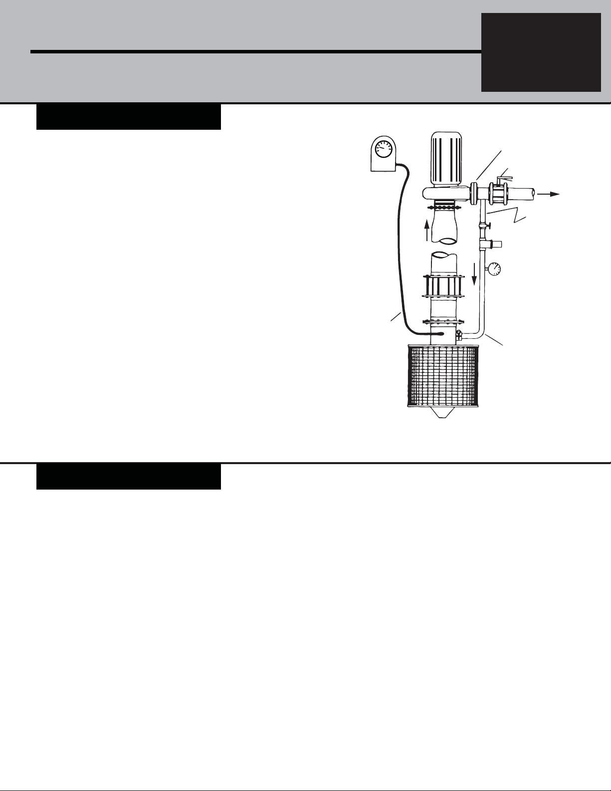
AUTOMATIC PUMP
SAFETY SHUT-OFF
CONTROL
1/4” TUBING
SUCTION
FLOW
CHECK
VALV E
SYSTEM
PUMP
PC
PUMP DISCHARGE
(MAIN LINE)
BUTTERFLY
VALV E
FLOW TO
SYSTEM
NOTE: TO ACHIEVE
GATE
VALV E
NECESSARY
BACKWASH PRESSURE,
A BOOSTER PUMP MAY
BE REQUIRED HERE.
IN-LINE
STRAINER*
PRESSURE
GAUGE*
TO BACKWASH
NOZZLES
6. Your PC Screen should not be installed:
a) Closer than 6-inches (155 mm) to any object.
b) In a con ned area (side culvert, large pipe, etc.) with no means of transferring
debris away from the screen.
c) In a current over 3 mph (4.83 km/hr), unless it is protected by an upstream
barricade or bell-shield.
Installation & Operation
INSTALLATION
1. Attach the PC Screen’s anged outlet to
pump’s suction/inlet pipe, using an appropriate
adapter, if required. Consult your LAKOS
representative if you have questions.
2. Plumb one end of the backwash line into
your pump’s discharge pipe.
3. Thoroughly ush the backwash line of any
debris.
4. The backwash line should be plumbed
between the pump and a main line valve. This
valve can then be partially closed to create
su cient back-pressure during start-up. Note:
If pressure is inadequate for e cient backwash
operation, a booster pump will be necessary.
5. Install on the backwash line:
a) a properly-sized gate valve (or pressure
regulator if pressure exceeds 100 psi/6.9 bar);
b) an 8-mesh strainer (supplied); and
c) a pressure gauge.
OPERATION
1. Screen does not need more than 2-inches
of submergence because the screen’s
rotation breaks up any vortex that might
form.
2. Screen should rotate at a rate of at least
15 RPM.
3. Backwash jets should be pointed
a) downstream or toward the opposite
embankment when installed in moving
water,
b) toward the center when used in still
bodies of water, and
c) toward the surface when screens are
deeply submerged. The direction of these
spray jets can be easily set by rotating the
ange on the screen’s outlet pipe to adjust
the position of the spray bar.
4. To prevent impeded screen rotation
or actual damage, the PC must be safeguarded in extremely swift currents (over 3
LAKOS PLUM CREEK
SCREEN*
*Provided with basic system
Typical installation
mph {4.83 km/hr}) or in moving water with
unusually large debris, such as logs. Either
a bell-shield attached to the PC Screen
ange or an upstream barricade can o er
the necessary protection. If a barricade is
used, it must
a) be situated at least 6 to 8-inches (152 to
203 mm) from the screen and
b) provide enough clearance underneath
to allow water to ow to create a
depression under the screen to prevent
silt build-up. (Consult factory for design
assistance.)
5. Adding a Screen Retrieval System
to lift your PC Screen out of the water
during periods of inactivity is always
recommended and can prevent algae
growth on the screen’s mesh covering.
Page 2
LAKOS PC SCreen Installation Guide
Flow Rates & Pressures
MAXIMUM FLOW RATE
(10 & 18 Mesh) (30 Mesh)
MODEL
PC 915
PC 1415
PC 924
PC 1424
PC 1924
PC 2424
PC 2924
PC 3424
*This pressure required at the PC Screen connection. If pressure is not adequate for e cient backwash operation, a booster pump
may be necessary
U.S. gpm
350
560
650
1000
1350
1700
2050
2400
m3/hr
80
130
150
230
305
385
465
545
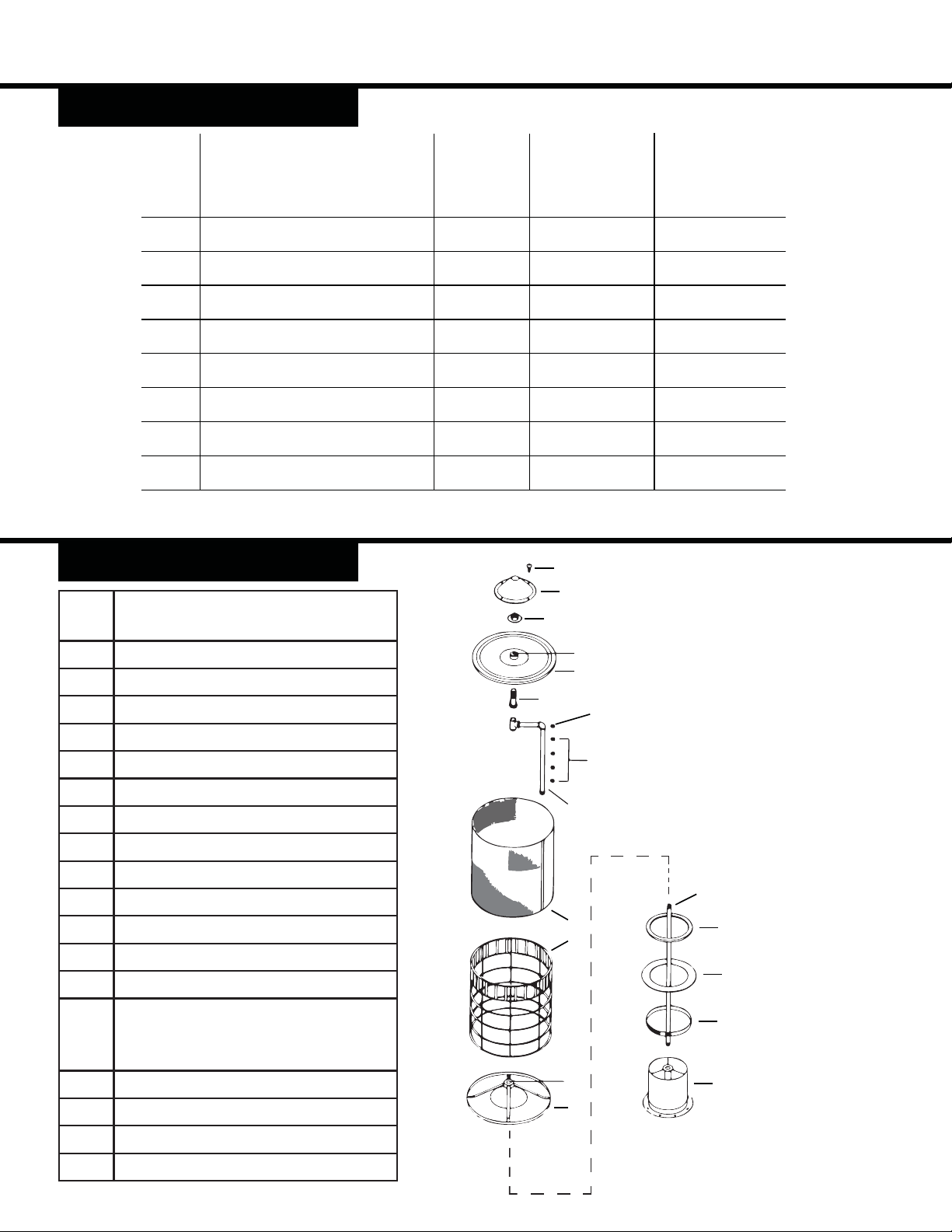
Parts Listing
Item #Description
1 Screen outlet pipe assembly
2 Band clamp
3 E.P.D.M. rubber seal
4 Plastic ring
5 Axle pipe
U.S. gpm
250
400
450
700
950
1200
1450
1700
m3/hr
60
90
105
160
215
275
330
385
BACKWASH
RETURN LINE
CONNECTION
(inches)
1-1/4
1-1/4
1-1/4
1-1/2
1-1/2
1-1/2
2
2
*REQUIRED
BACKWASH
PRESSURE
psi
55-80
60-80
60-100
65-100
70-100
75-100
75-100
75-100
14
13
12
18
11
10
kPa
385-560
420-560
420-705
455-705
490-705
525-705
525-705
525-705
16
15
APPROXIMATE
BACKWASH FLOW
AT PROPER PRESSURE
U.S. gpm
10
15
12
18
25
39
41
50
m3/hr
2.5
3.5
2.5
4.0
5.5
8.0
9.5
11.5
Note: When ordering
replacement parts, please
speci y the complete model
number of your PC Screen
(example: PC-242410GE12) to
facilitiate shipment of a part
compatible with your particular
unit.
6 Spider bushing cap assembly
7 Frame & drive vane assembly
8 Screen cover & rivet pack for frame
9 Jet pipe assembly
10 Delrin spindle
11 Bushing & end cap assembly
12 Spindle nut & washer
13 Hub cap
14 #10 stainless steel 5/8-inch screw
for end caps & hub cap (package
contains up to 64 scerws)
15 Backwash spray nozzles (1 to 6x)
16 Drive nozzle
17 Spider bushing
18 Lid bushing
17
9
5
8
7
6
4
3
2
1
Page 3
Troubleshooting
If your PC Screen fails to rotate properly or if debris passes through the screen into your
water system or accumulates on the screens surface, discontinue pumping. Do not resume
pumping until the di culty has been located and corrected. Use the following chart
of potentially troublesome situations as a checklist to help identify the source of your
screen’s particular problem.
Limited Warranty
For warranty and patent information,
please visit:
www.lakos.com/warranty-info
1365 North Clovis Avenue
Fresno, California 93727 USA
Telephone: (559) 255-1601
FAX: (559) 255-8093
www.lakos.com
[email protected]
Debris
Accumulating
on Screen
Debris
Passing
Through
Screen
X X 1. Water being pumped at a
X X 2. Undersized screen mesh for
X 3. Oversized screen mesh
X X X 4. Clogged backwash line
X X X 5. Undersized backwash line
X 6. Torn screen
X X X 7. Plugged drive jet or
X X 8. Pressure shortage at pump
X X 9. Heavy silt build-up under the
X X 11. Screen located in a closed
X X 12. Unsupported, poorly
X X 13. Algae growth on screen
X X X 14. Mechanical malfunctions
X X 15. Foreign object wedged
X X X 16. Screen located in swift
X X 17. Domed screen in backwash
For additional information, please vist:
http://www.lakos.com/irr-products/pc-screen
and refer to brochure PC-115
Insu cient
Potential Problem Sources
Screen
Rotation
rate in excess of the screen’s
capacity
the ow rate desired
for the oating debris
encountered
backwash strainer
or screen
screen
X 10. Screen installed too close to
another object
area where vegetation & other
debris remain trapped
supported or damaged pump
suction/inlet pipe
(usually after pumping
has been suspended for a
prolonged period)
(worn moving parts, seals, etc.)
against screen
current without a protective
barricade or bell-shield
line has not been removed
PC-108 (1/14)
 Loading...