

Lakos ISF 915, ISF 3434, ISF 1415, ISF 1424, ISF 2424 Installation Manual
Separators and Filtration Solutions
ISF SELF-CLEANING PUMP INTAKE SCREENS
INSTALLATION & START-UP INSTRUCTIONS
PRE-INSTALLATION CHECKLIST
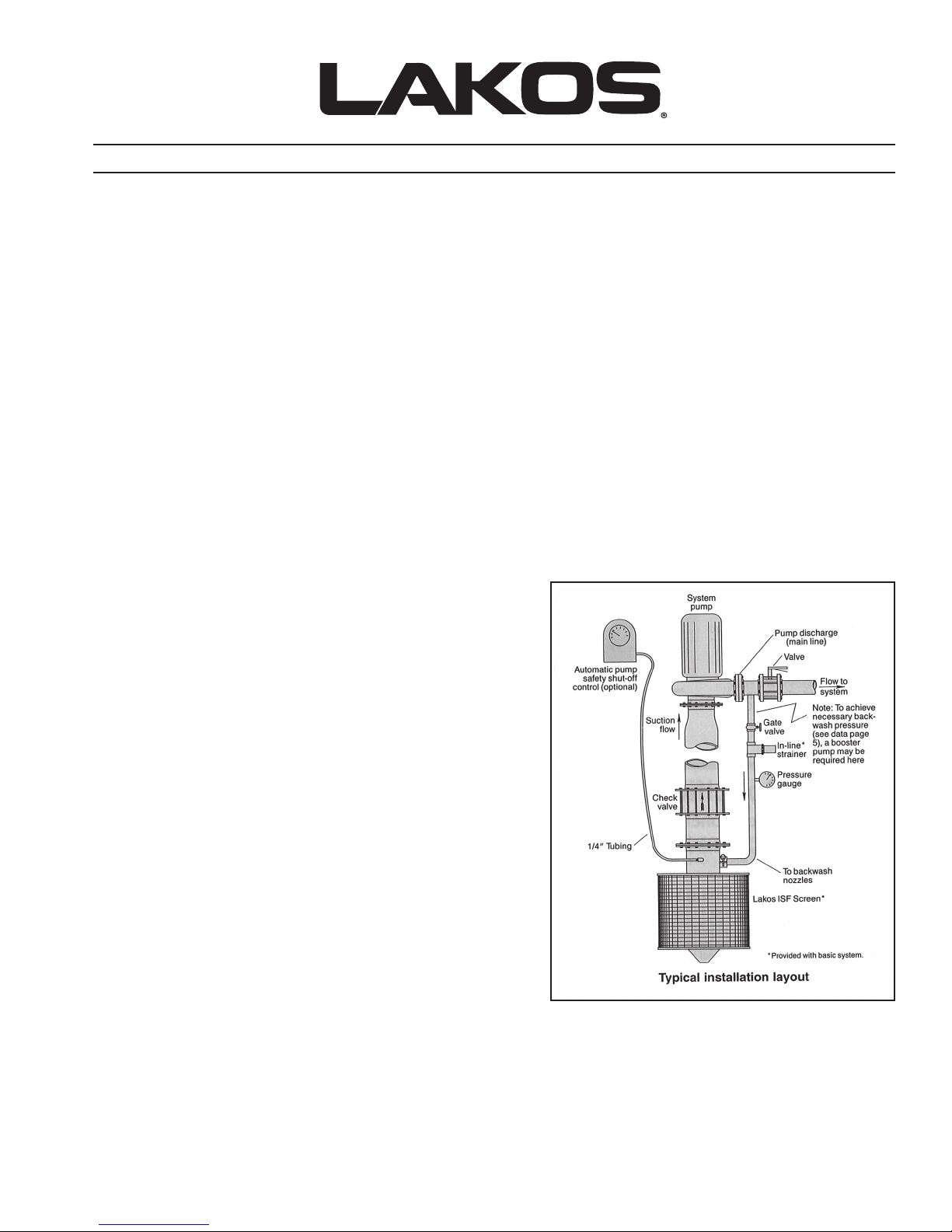
1. Consult the General Specifications on reverse for the pumping pressure range required on the backwash line at the ISF
Screen. Note: If pressure is less than the minimum required to operate the screen and backwash system, a booster pump is
required.
2. IMPORTANT: The ISF Screen is a water-pressure driven and backwashed device. If the screen does not have the required
pressure delivered to the return line connection at the screen, the screen will not work. Carefully measure the return line size to
insure that the proper pressure is delivered to the ISF Screen. Do not install a line smaller than that recommended on reverse
(see Dimensions, “C”).
3. Be sure you will not be pumping at a rate in excess of your ISF Screen’s maximum flow range. See General Specifications on
reverse.
4. It is very important to thoroughly flush sand, pebbles, insects, glue and any other debris from the backwash line before
installation start-up. Failure to do this could result in plugged spray jets inside the ISF Screen.
5. Make certain pump’s suction/inlet pipe is properly supported and sufficiently elevated to allow your ISF Screen to rotate freely.
6. Your ISF Screen should not be in
a) Closer than 6-inches (155 mm) to any object.
b) In a confined area (side culvert, large pipe, etc.) with no means of transferring debris away from the screen.
c) In a current over 3 mph (4.83 km/hr), unless it is protected by an upstream barricade or bell-shield.
stalled:
INSTALLATION INSTRUCTIONS
1. Attach the ISF Screen’s flanged outlet to pump’s suction/inlet pipe,
using an appropriate adapter, if required. Consult your LAKOS
representative.
2. Plumb one end of the backwash line into your pump’s discharge
pipe.
3. Thoroughly flush backwash line of any debris.
4. Backwash line should be plumbed between the pum
line valve. This valve can then be partially closed to create sufficient
back-pressure during start-up. Note: If pressure is inadequate for
efficient backwash operation, a booster pump will be necessary.
5. Install on the backwash line: a) a properly-sized gate valve (or
pressure regulator if pressure exceeds 100 psi/6.9 bar); b) an
8-mesh strainer (supplied); and c) a pressure gauge.
p and a main
OPERATION GUIDELINES
1. Screen does not need more than 2-inches of submergence because
the screen’s rotation breaks up any vortex that might form.
2. Screen should rotate at a rate of at least 15 RPM.
3. Backwash jets should be pointed a) downstream or toward the
opposite embankment when installed in moving water, b) toward the
center when used in still bodies of water, and c) toward the surface
when screens are deeply submerged. The direction of these spray
jets can be easily set by rotating the flange on the screen’s outlet pipe to adjust the position of the spray bar.
4. To prevent impeded screen rotation or actual damage, the ISF must be safe-guarded in extremely swift currents (over 3 mph
{4.83 km/hr}) or in moving water with unusually large debris, such as logs. Either
flange or an upstream barricade can offer the necessary protection. If a barricade is used, it must a) be situated at least 6 to
8-inches (152 to 203 mm) from the screen and b) provide enough clearance underneath to allow water to flow to create a
depression under the screen to prevent silt build-up. (Consult factory for design assistance.)
5. Adding a Screen Retrieval System to lift your ISF Screen out of the water during periods of inactivity is always recommended
and can prevent algae growth on the screen’s mesh covering.
a bell-shield attached to the ISF Screen
(continued on reverse)
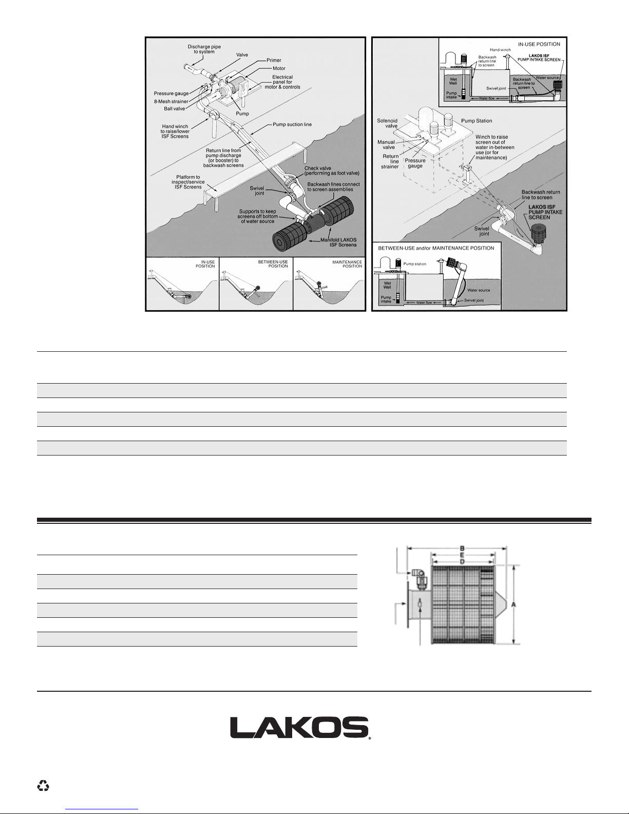
SAMPLE
INSTALLATIONS
GENERAL SPECIFICATIONS
Model U.S. gpm m
10 Mesh 30 Mesh Outlet Pipe Weight Backwash Pressure Proper Pressure
Approximate
3
/hr. U.S. gpm m3/hr. in mm lbs. kg psi bar U.S. gpm m3/hr.
ta wolF hsawkcaBderiuqeRneercSFSIetaR wolF mumixaM
ISF 915 350 80 250 60 6 152 29 13.2 55-80 3.8-5.5 10 2.5
ISF 1415 600 136 500 114 6 152 31 14.0 60-80 4.1-5.5 15 3.5
ISF 1424 1100 250 800 182 10 254 60 27.3 65-100 4.5-6.9 18 4.0
ISF 2424 1900 431 1300 305 12 305 75 34.1 75-100 5.1-6.9 36 8.0
ISF 3434 2700 613 1900 432 16 406 100 45.5 75-100 5.1-6.9 50 11.5
Frame & Propelling Vanes: Reinforced fiberglass composite
End Caps, Screen Outlet, Interior Pipe & Fittings: Stainless steel
Screen: 10 or 30 mesh stainless steel or phospher bronze
Bushings: Pressure-lubricated, ultra-high molecular weight (UHMW) polyethylene
Outlet: All are ANSI compatible flanges
C*
Backwash
DIMENSIONS
Model in. mm in. mm in.-NPT in. mm in. mm
CBA * D E
Return Line
Connection
ISF 915 15 381 19 483 1-1/4 9 229 10 254
ISF 1415 15 381 24 610 1-1/4 14 356 15 381
ISF 1424 24-1/2 622 24-1/2 622 1-1/2 14 356 15 381
ISF 2424 24-1/2 622 34-1/2 876 1-1/2 24 610 25 635
ISF 3434 24-1/2 622 47 1194 2 34 865 35 889
*Minimum backwash line size. Do not reduce.
The information, specifications and performance data stated in this literature are representative of engineering and production standards at the time of publication. Despite quality control, slight variations
may occur due to manufacturing, product design improvements and/or sample selection. Actual data may be revised without notice, and you are encouraged to verify pertinent data with the manufacturer
when appropriate.
ISF
Screen
Outlet,
connects
to pump
1/4" hose barb fitting for connection of
intake
Automatic Pump Safety Shut-off Control
For troubleshooting or special assistance, please contact your LAKOS representative or call us:
1365 N. Clovis Avenue • Fresno, California 93727 USA
Fax: (559) 255-8093
Printed on recycled paper
Separators and Filtration Solutions
• Telephone: (559) 255-1601
www.lakos.com • E-mail: info@lakos.com
LS-651 Rev. (3/13)
 Loading...