

Page 1
TWELVE LEAD TASK
TRAINER
Directions for Use
Page 2

Laerdal
2
Page 3

TABLE OF CONTENTS
Laerdal Recommends 4
Items Included 5
Skills Taught 5
Features 6
Overview 7
Operation 7
Running Scenarios 12
Battery Replacement 13
Replacement Parts 14
Laerdal
3
Page 4

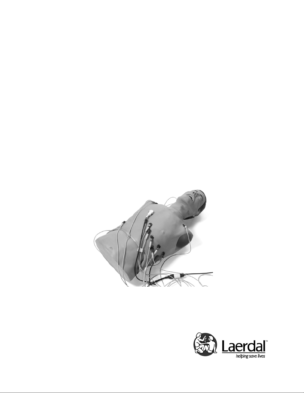
Twelve Lead Task Trainer (260-20001) is a torso
The
lifelike manikin designed to realistically simulate airway
management scenarios and train students in the proper
utilization of 12 lead ECG devices, including the proper
connection of patient cable, acquisition and
interpretation of 12 lead ECG, and understanding and
utilizing the AMI algorithm and local protocols relating to
treatment of suspected or confirmed AMI.
The manufacturing excellence and ease of replacing
trainer individual parts should provide many sessions of
training when reasonable care and maintenance is
practiced.
Laerdal Recommendations:
7.5 ET Tube
Use Manikin Lubricant prior to training sessions
Safety Precautions used during Defibrillation
of a Patient/Trainer
1. Read and follow all safety and operating
instructions provided with your defibrillator
and associated equipment.
2. This trainer can be shocked with actual
voltages and current used on a live
patient. All precautions and safety
measures must be used during the
defibrillation and pacing phases of training.
Failure to follow safety measures could
result in injury or death to operators,
students or onlookers not heeding these
warnings.
Laerdal
4
Page 5

Items Included:
(1) Adult Manikin Torso with Electronics
(1) Wired Remote Control
(2) “C” Cell Batteries
(1) Manikin Lubricant
(1) Tank Top
(1) Carry Case
(1) Laerdal Global Warranty Booklet
(1) Directions for Use
Skills Taught:
Airway Management:
• Oral/nasal/digital intubation
• Right mainstem intubation
• Oropharyngeal/Nasopharyngeal airway insertion
• Bag-Valve Mask ventilation
• Suctioning techniques
• Abdominal thrust
• Combitube insertion and ventilation
Cardiac Related Skills:
• Carotid pulse palpation, manually generated
• Closed chest compressions
• Connection sites for four limb leads and V1
through V6
• Compatible with 12-lead defibrillator/monitors
• Defibrillation via hands free cables or paddles
• Pacing with option to capture or fail to capture
• Closed chest compressions
Training in:
• Proper connection of patient leads
• Operation of 12 lead ECG devices
• Acquisition and interpretation of 12 lead
ECG
• Understanding and utilization of current
treatment algorithms
• Understanding and utilization of local
protocols relating to and treatment of
suspected or confirmed electrical
abnormalities
Laerdal
5
Page 6

Features:
•
• Scenarios of up to
nine (9) ECG choices
may be programmed.
• System is capable of
being shocked at 360
joules and receiving
fifteen (15) sets of
three (3) shocks per
set.
• Operates on DC
current from a
replaceable battery
contained in the
manikin torso and will
accommodate an AC
adapter.
• Battery can operate
the system for 40
hours of normal
operation.
• When using battery,
system will turn “off”
after fifteen (15)
minutes of inactivity.
Excluding remote,
operating system is
contained within the
manikin.
• Complete system
weighs no more than
forty (40) pounds.
• Meets FCC and CE
requirements
Laerdal
6
Page 7

Overview –
The AST-12 unit is used in a teaching
environment to display 12 lead signals on
an ECG monitor. The unit is capable of
storing up to nine (9) training scenarios.
Each one can contain as many as nine (9)
steps each. The unit supports defibrillation
and pacing training and allows for
advancement to next waveform in a scenario
on a defib pulse. The unit incorporates
a two (2) line by 16 character LCD to
display current waveform information,
as well as the current scenario status.
The unit may be powered through a 12VDC 100mA AC
adapter or by two (2) ‘C’ cell batteries. When on battery
power, the unit will automatically shut off after 15
minutes of inactivity.
Operation –
This operational section assumes that unit is in default
configuration with no scenarios programmed into the unit.
When unit is powered “On,” it will begin an initialization
routine. During this time, the remote control unit will
display the model name on top line and version number
on bottom line.
After a brief delay, unit will initialize to waveform mode
‘WFM’ with pacing disabled ‘N’ and set to waveform #21
‘Normal Sinus’. At this point, the unit will output 12 lead
waveform data.
Using the remote control unit as a guide, and starting at
the top left, the displayed items are:
• Current mode (MOD)
• Current scenario # (SCEN)
• Current scenario step # (STEP)
• Scenario defib step advance (DFIB)
• Pacing mode (PACE)
• Scenario step timer (TMR)
On the bottom of remote control are the waveform
number (#) (WAVEFORM) and waveform name.
Laerdal
7
Page 8

Waveform mode –
While in waveform mode, the unit will display the
current mode and pacing status on the top line and the
current waveform # and name on the bottom line. The
unit will output 12 lead waveform data for the currently
selected waveform. Waveform mode also allows
waveform pacing.
To enable pacing:
Press the ‘Pace’ button while in waveform mode. When
waveform pacing is enabled, the top line of the LCD will
display the letter ‘Y.’ This is located under the ‘PACE’
text on the remote. The letter ‘N’ will be displayed when
pacing is not enabled. When enabled (‘Y’), the manikin
can receive pacing output from a pacer unit. Once the
pacer unit output reaches approximately 80 – 90 mA, the
AST-12 allows electrical capture.
Pacing enabled – ‘Y’
Pacing not enabled – ‘N’
Program mode:
To enter program mode, press ‘Prog>’ button. This is
where all scenario program editing is done. The
unit allows for storage of up to nine (9) scenarios having
nine (9) steps each. During editing, the user may use any
of the digits on the numeric keypad or the ‘+’ and ‘-’
buttons.
While in program mode, the unit will display on the top
line:
• Current mode
• Current scenario #
• Current scenario step number
• Defib step advance
• Step timer status
The bottom line will display the waveform # and name
for the indicated scenario and step.
Laerdal
8
Page 9

Assuming there are no scenarios currently programmed,
the display will look like this:
PRG 1 1 N 0:00
000 END SCENARIO
Starting at the top left:
PRG – Current mode – programming mode
1 – Current scenario number
1 – Current scenario step number.
N – Scenario will not advance to the next step with a
defib pulse.
0:00 – Timer is disabled for this step
And the bottom line:
000 – indicates this step is the last step of the scenario
NOTE: Waveform 000 (END SCENARIO) will end a
scenario with fewer than nine (9) steps, and a timer value
of 0:00 will disable the timer for the current step.
Programming the unit –
NOTE: If you hold the ‘Prog>’ button down for more
than 5 seconds, the scenarios data will be updated and
saved.
To move cursor while in programming mode, press the
‘Prog>’ button. When you reach the end of the bottom
line, the cursor will go back to the front of the top line.
1. Move the cursor to the ‘SCEN’ position
2. Select the scenario number (1 through 9) you
want to edit by pressing a number or the +/-
buttons on the keypad
3. Move the cursor to ‘STEP’ position
4. Select the step number (1 through 9) you want to
edit by pressing a number or the +/- buttons on
the keypad
5. Move the cursor to the ‘DFIB’ position
6. Select whether or not you want your scenario to
advance (Y or N) to the following step when it
detects a defib pulse by pressing the +/- buttons
on the keypad.
Laerdal
9
Page 10

7. Move the cursor to the ‘TMR’ position
8. Select the amount of time (0 thru 9:59) this step
will run before advancing to the next step by
pressing numbers or the +/- buttons on the
keypad. (To DISABLE the timer for this
step, set the timer to 0:00.)
NOTE: If ‘DFIB’ is set to ‘N’ and ‘TMR’ is set to 0:00,
the scenario will not automatically advance to the
next step from this step. This will allow you to decide
when to advance to the next step manually by pressing
the ‘+’ button on the keypad.
To end a running scenario, either repeatedly press
the ‘+’ button to advance through each step or press the
‘Run’ button to end it immediately.
9. Move the cursor to the ‘WAVEFORM’ position
10. Select the waveform number (0 through 80) to
use for this scenario step.
To END SCENARIO, select waveform 0.
NOTE: Be sure to end each scenario with waveform 000.
If ‘END SCENARIO’ is selected as step number 1, the
scenario will not appear to run, since this waveform will
tell it to end as soon as it starts.
If you have five (5) steps in your scenario, and want to
change it to a three (3) step scenario, and you do not
select ‘END SCENARIO’ as the waveform for step 4,
instead of stopping after step 3, the scenario will
continue with step 4 since it was not changed to ‘END
SCENARIO.’ It will then finish step 4 and continue on
with step 5, since the data was not removed from the
scenario.
11. Either press and hold the ‘PROG>’ button for five
(5) seconds to save your changes or start the
process again by selecting a different scenario or
step number. Before saving, the unit will prompt
the user to verify the edits should be saved (+ for
yes and – for no).
Laerdal
10
Page 11

Any waveform is paceable except “END SCENARIO”.
000 End Scenario 040 SR74_Couplet
001 SR_78 041 ST_120_PAC
002 SR_76 042 ST100_MulPVC
003 SR_92 043 AVBlk_34_PVC
004 STach_118 044 AVBlk_60
005 STach_144 045 Vent_Escape
006 STach_148 046 1 _Couplet
007 STach_156 047 2 _Type II
008 STach_162 048 SBrady34_ ST
009 STach_154 049 SBrady50_ ST
010 ST106_UniPVC 050 2 _Type_II
011 SR_66 051 SR_80
012 SR_72 052 S_Tach_168
013 SR_86 053 SR_84_PJC
014 SR_98 054 SR_58_Bigem
015 STach_110 055 Inj_Ant
016 ST_114 056 Inj_AntSept
017 ST_146 057 Inj_AntSept
018 ST_108 059 Inj_Inferior
019 SR_88 060 Inj_Inferior
020 SR_82 061 Inj_Inferior
021 SR_76 062 Inj_Inferior
022 PSVT 063 Inj_Inf/Post
023 S_Brady_58 064 Inj_Inf/Post
024 SBrady50_PAC 065 Inj_Sept/Inf
025 SR_64_PAC 066 AVBlk_60
026 SBrady58_PAC 067 1 _Wide_QRS
027 S_Tach_117 068 Ideovent
028 ST102Uni_PVC 069 Paced
029 SVT_198 070 Paced
030 Afib_76 071 Paced_54
031 AF_PVC_Coup 072 Paced_60
032 AF_64_AbVent 073 Paced
033 Aflut_96 074 Paced
034 Aflut_64 075 Paced_98
035 Junct_54_^ST 076 Paced
036 Junct_60_ ST 077 Paced
037 Junct_58_ ST 078 Paced
038 SR_58_Bigem 079 Paced_60
039 ST118_Trigem 080 Paced_108
Laerdal
11
Page 12

Running scenarios –
To run a scenario:
1. Start in the waveform (WFM) mode
2. Press the ‘RUN’ button and the display will switch
to selection ‘SEL’ mode and prompt the user to
select a scenario number
3. Select the scenario by pressing a number or the
+/- buttons on the keypad. The rest of the top
line of the display will show the ”DFIB” status and
“TMR” status of the first step of the current
scenario.
4. Once you have selected the scenario you want to
run, press the ‘Run’ button again to start the
scenario.
The text under ‘MOD’ will animate the word ‘RUN’ to
indicate a scenario is running.
The number under ‘SCEN’ indicates the currently
running scenario number.
The number under ‘STEP’ indicates the currently running
step number.
The letter under ‘DFIB’ indicates whether or not defib
advance is enabled
The number under ‘TMR’ indicates the time remaining
before the scenario will advance to the next step. The
bottom line displays the currently used waveform
number and name.
for the current step.
Laerdal
12
Page 13

To manually advance to the next step, press ‘+.’
To manually end the scenario, press ‘Run.’
When the scenario has been completed, the unit will
revert back to waveform mode using the waveform from
the last scenario step.
Battery Replacement
There are two “C” cell batteries located on the trainer’s
right side.
To replace these batteries:
Lift skin from the shoulder of
the torso and pull down toward
the bowel. An insert module will
be exposed on the right side of
the manikin torso. The upper
module is removed to expose
the battery compartment.
Replace the batteries as needed.
In the event this trainer is stored
for more than a few weeks,
remove the batteries to keep
possible battery leakage from
damaging the battery holder.
Laerdal
13
Page 14

Replacement Parts:
Part Number: Description:
260-00650 Head
260-00150 Chest Skin
100-00750 Carry Case
Cautions and Warnings
This product contains Natural Rubber latex which
may cause allergic reactions when in contact with
humans.
Laerdal
14
Page 15

Laerdal
15
Page 16

©Laerdal Medical. All rights reserved. Printed in USA
1004856 Rev. B
December 20, 2006
Laerdal
16
 Loading...