

Page 1
VAZ VEHICLES
VAZ-21213, VAZ-21214, VAZ-21214-20, VAZ-21215
REPAIR MANUAL
Page 2

2
Contents
Section 1. General data..........................................................4
Section 2. Engine ..................................................................7
Engine - removal and refitting..........................................12
Cylinder block..................................................................19
Inspection and repair..................................................19
Pistons and connecting rods ...........................................21
Selecting piston to cylinder ........................................23
Dismantling and reassembly......................................23
Crankshaft and flywheel ..................................................24
Design description......................................................24
Inspection and overhaul.............................................24
Cylinder head and valve gear..........................................26
General description....................................................26
Valve clearance adjustment.......................................27
Cylinder head - removal and refitting.........................28
Cylinder head - dismantling and reassembly ............28
Camshaft and timing gear ...............................................32
Cooling system ...............................................................34
Lubrication system ...........................................................38
Fuel system .....................................................................42
Carburettor.......................................................................46
Exhaust gas recirculation system....................................55
Exhaust system ...............................................................46
Chapter 3. Power train.........................................................57
Clutch..............................................................................57
Gearbox...........................................................................64
Transfer box....................................................................73
Drive line .........................................................................80
Rear axle.........................................................................84
Front axle ........................................................................96
Chapter 4. Wheel suspensions ...........................................100
Front suspension...........................................................102
Rear suspension............................................................110
Chapter 5. Steering ...........................................................115
Steering - inspection, check and adjustment ................116
Steering mechanism ......................................................118
Chapter 6 Braking system..................................................121
Front brakes..................................................................128
Rear brakes...................................................................130
Handbrake .....................................................................134
ëhapter 7. Electrical system...............................................135
Wiring and fuses ...........................................................135
Battery...........................................................................136
Alternator .......................................................................140
Starter motor .................................................................146
Ignition system ..............................................................149
Lighting and signalling...................................................156
Windscreen wiper/washer.............................................159
Instruments....................................................................163
Chapter 8. Bodywork.........................................................167
Bodywork - repair .........................................................169
Paintwork.......................................................................172
Door...............................................................................176
Bonnet, bumpers...........................................................179
Bodywork glazing and windscreen washers.................180
Instrument panel, seats .................................................181
Heater unit.....................................................................183
Chapter 9. VAZ-21213 vehicle modifications, alternative and addi-
tional equipment...............................................................185
VAZ-21214 vehicle........................................................185
Engine repair - description............................................185
Central Injection Unit .....................................................186
VAZ-21214-20 vehicle...................................................189
Engine 21214-10...........................................................190
VAZ-21215-10 vehicle...................................................197
Cooling system..............................................................200
Lubrication system ........................................................202
Fuel system...................................................................202
Exhaust emission system..............................................203
Electrical system ...........................................................203
Steering with BREED «SRS-40»
driver’s airbag in the steering wheel ............................209
Attachments.....................................................................212
Д‚ЪУПУ·ЛОЛ ЗДб-21213, ЗДб-21214, ЗДб-21214-20, ЗДб-21215
кЫНУ‚У‰ТЪ‚У ФУ ВПУМЪЫ ‡‚ЪУПУ·ЛОВИ
© ЙЦзЦкДгъзхв СЦиДкнДеЦзн кДбЗанаь Д/й ДЗнйЗДб
© Д‚ЪУ˚-‡Б‡·УЪ˜ЛНЛ: ЗУО„ЛМ л. з., дУБОУ‚ и. г., дУТ‡В‚ л. з.
© иВВ‚У‰ б. ДМЛТУ‚УИ, а. лЪ‡МНУ‚УИ
© е‡НВЪ-УЛ„ЛМ‡О ЛБ„УЪУ‚ОВМ Еде миДЗк Дй ДЗнйЗДб. дУПФ¸˛ЪВМ‡fl ‚fiТЪН‡ Л УЩУПОВМЛВ - З. ДО‡В‚, З. а‚НУ‚, З. еЛЪУЩ‡МУ‚. ЪВО. (8482) 22-54-19.
àÁ‰. ‹ 0021311
Page 3

About this manual
This Manual provides information on routine maintenance and servicing and is intended for engineers
and mechanics of service outlets, garages and workshops.
The Manual covers the following models:
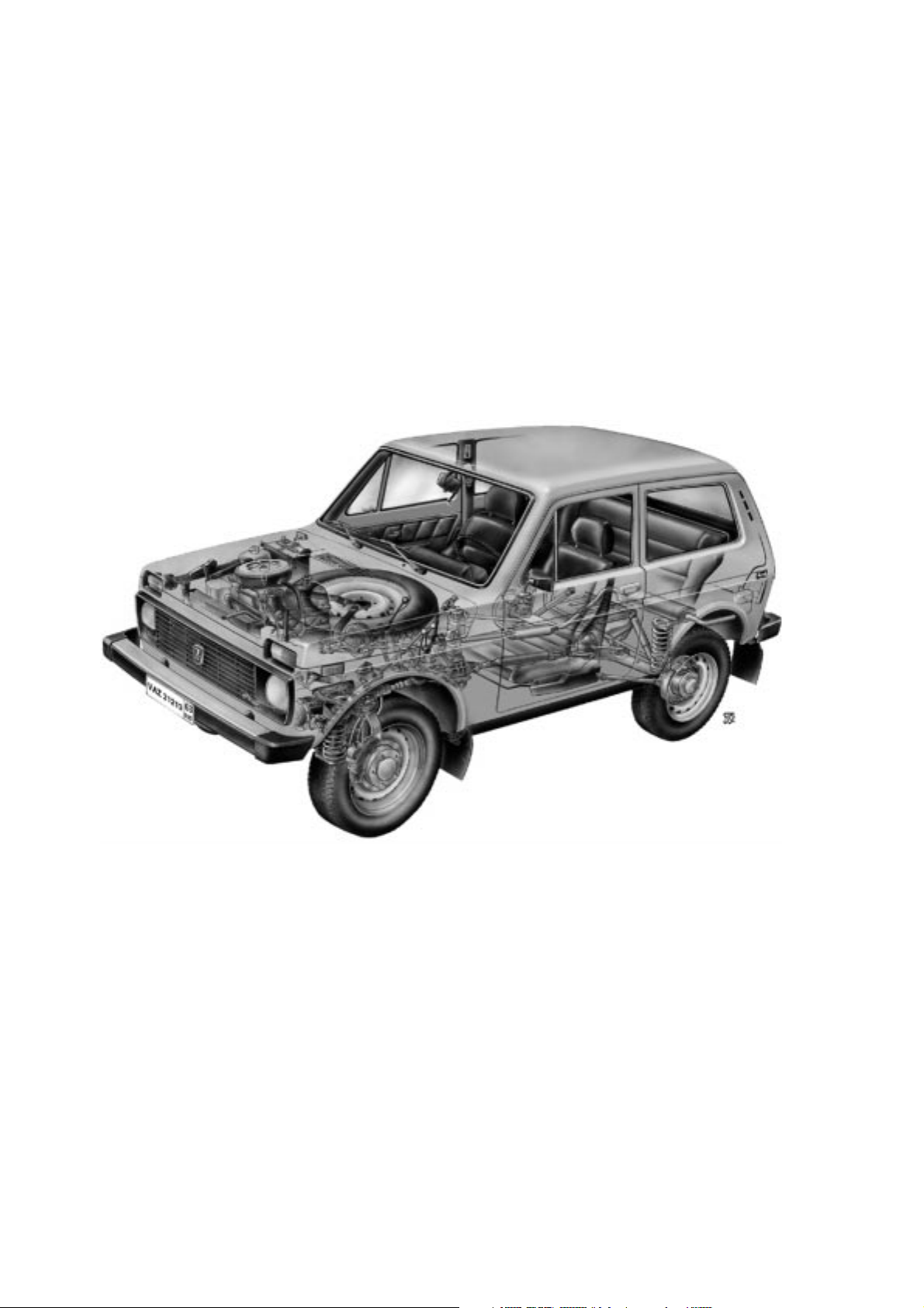
VAZ-21213 model - an off-road vehicle, three-door body of all-steel unitary construction,
with 1.7 litre carburettor engine;
VAZ-21214 model - with 1.7 litre Central Fuel Injection Engine;
VAZ-21214-20 model - with 1.7 litre Sequential Fuel Injection Engine;
VAZ-21215 model - with Turbo Diesel Engine.
The chapters of the manual give full descriptions of VAZ-21213 vehicle units. For general description,
service and repair procedures applicable to other models, refer to Section 9 where you can also find the
information on additional and alternative equipment fitted to the vehicles.
The Manual provides a detailed description of service operations on the base of OEM parts, with help-
ful information on fault diagnosis, along with clear indications on removal and refitting, dismantling and
reassembly, adjustment and repair of various vehicle units.
We recommend to use special tools and working facilities as listed in Attachment No 2. Tighten the
thread connections to torques specified in Attachment No 1. Basic adjustments and inspection checks are
outlined in Attachment No 3. Refer to Attachment 4 for recommended lubricants and fuels.
Due to the on-going process of vehicle improvement aimed to enhance the VAZ vehicle reliability and
performance, the manufacturer can make alterations and design changes which may fail to enter this publication. Such changes and alterations will be incorporated into our manuals at the earliest opportunity.
The Manual describes the vehicle design as of October 1999.
3
Page 4

Section 1. General Data
Table 1-1
TECHNICAL SPECIFICATION
Features VAZ-21213 VAZ-21214 VAZ-21214-20 VAZ-21215
General
Number of seats 5 5 5 5
Kerb weight, kg 1210 1210 1210 1240
Payload, kg 400 400 400 400
Overall dimensions Fig.1-1
Maximum braking distance at GVW and 80 km/h
on horizontal dry flat asphalt road, not greater, meters:
• with service braking system applied 40 40 40 40
• with emergency system applied (either of two service braking circuits) 90 90 90 90
Maximum speed* in top gear, km/h:
• with driver and passenger 137 137 137 130
• at full load 135 135 135 128
Acceleration time*, 0 to 100 km/h through gear shifting, seconds:
• with driver and passenger 19 19 19 22
• at full load 21 21 21 24
Engine
Model 21213 21214 21214-10 DHW (XUD-9SD)
Type
Four-stroke, Four-stroke, Four-stroke, Four-stroke,
petrol, carburettor petrol, CFI petrol, sequential injection turbo diesel
No of cylinders four in-line four in-line four in-line four in-line
Bore x stroke, mm 82ı80 82ı80 82ı80 83ı88
Capacity, litre 1.69 1.69 1.69 1.905
Compression ratio 9.3:1 9.3:1 9.3:1 21.5:1
Maximum power:
as per GOST 14846 (net), at least, ÍW (h.p.) 58 (78.9) 58 (78.9) 58.5 (79.6) 55 (74.8)
as per ISO 1585, ÍW 58 58 58.5 55
Maximum crankshaft speed at maximum power, rpm 5200 5400 5000 4600
Firing order 1-3-4-2 1-3-4-2 1-3-4-2 1-3-4-2
____________________________________
* Measured using a special procedure
4
Page 5

Features VAZ-21213 VAZ-21214 VAZ-21214-20 VAZ-21215
Power train
Clutch single dry plate, diaphragm spring
Clutch release mechanism hydraulic, servo spring
Transmission 5-speed, synchro units on all forward gears
Gear ratio:
• first gear 3.67 3.67 3.67 3.67
• second gear 2.10 2.10 2.10 2.10
• third gear 1.36 1.36 1.36 1.36
• fourth gear 1.00 1.00 1.00 1.00
• fifth gear 0.82 0.82 0.82 0.82
• reverse gear 3.53 3.53 3.53 3.53
Transfer case two-gear, lockup differential
Gear ratio:
• top gear 1.2 1.2 1.2 1.2
• bottom gear 2.135 2.135 2.135 2.135
Transfer case differential bevel gears, two pinion gears
Drive line:
• from transmission to transfer case flexible coupling and CV joints
• from transfer case to front and rear axles two universal joints on needle bearings with grease nipples and yokes
• from front axle to wheels open, with CV joints
Final drive ratio, front and rear axles bevel, hypoid
• gear ratio 3.9 3.9 3.9 3.9
• differential bevel, two pinion gears
Suspension and wheels
Front suspension independent, lower track control arms (wishbones), coil springs,
hydraulic telescopic shock-absorbers, anti-roll bar
Rear suspension rigid axle beam with Panhard rod and four trailing arms,
coil springs/hydraulic telescopic shock-absorbers
Wheels pressed-steel disc
• wheel rim 127J x 406 (5J x 16)
Tyres tubed, cross-ply or radial ply
size:
• cross-ply tyres 175 x 406 (6.95 x16),
• radial-ply tyres 175/80R16
5
Page 6

Features VAZ-21213 VAZ-21214 VAZ-21214-20 VAZ-21215
Steering
Steering mechanism globoidal worm, double-crest roller, steering ratio 16.4
Steering linkage three links, relay rod and two steering rods,
drop arm, idler arm and swing arms
Braking system
Service braking system:
• front brakes disc-type, floating caliper, automatic disc-to-pad clearance adjustment
• rear brakes drum-type, self-applying shoes and automatic shoe-to-drum clearance adjustment
• brake operation line foot-type, hydraulic, dual circuit, split diagonally, vacuum servo unit and pressure regulator
Handbrake cable-operated on rear wheels
Electrical system
Wiring diagram single-wire, negative earth type
Voltage, volts 12
Battery 6ëí-55Ä, 55 ampere-hour
Alternator AC, integral diode plate and electronic voltage regulator
Starter motor pre-engaged, solenoid switch and overrun clutch
Body
Type all-steel unitary construction, monocoque, three-door, double-space
6
Fig.1-1. Basic overall dimensions of VAZ-21213 vehicle
Page 7
Section 2. Engine
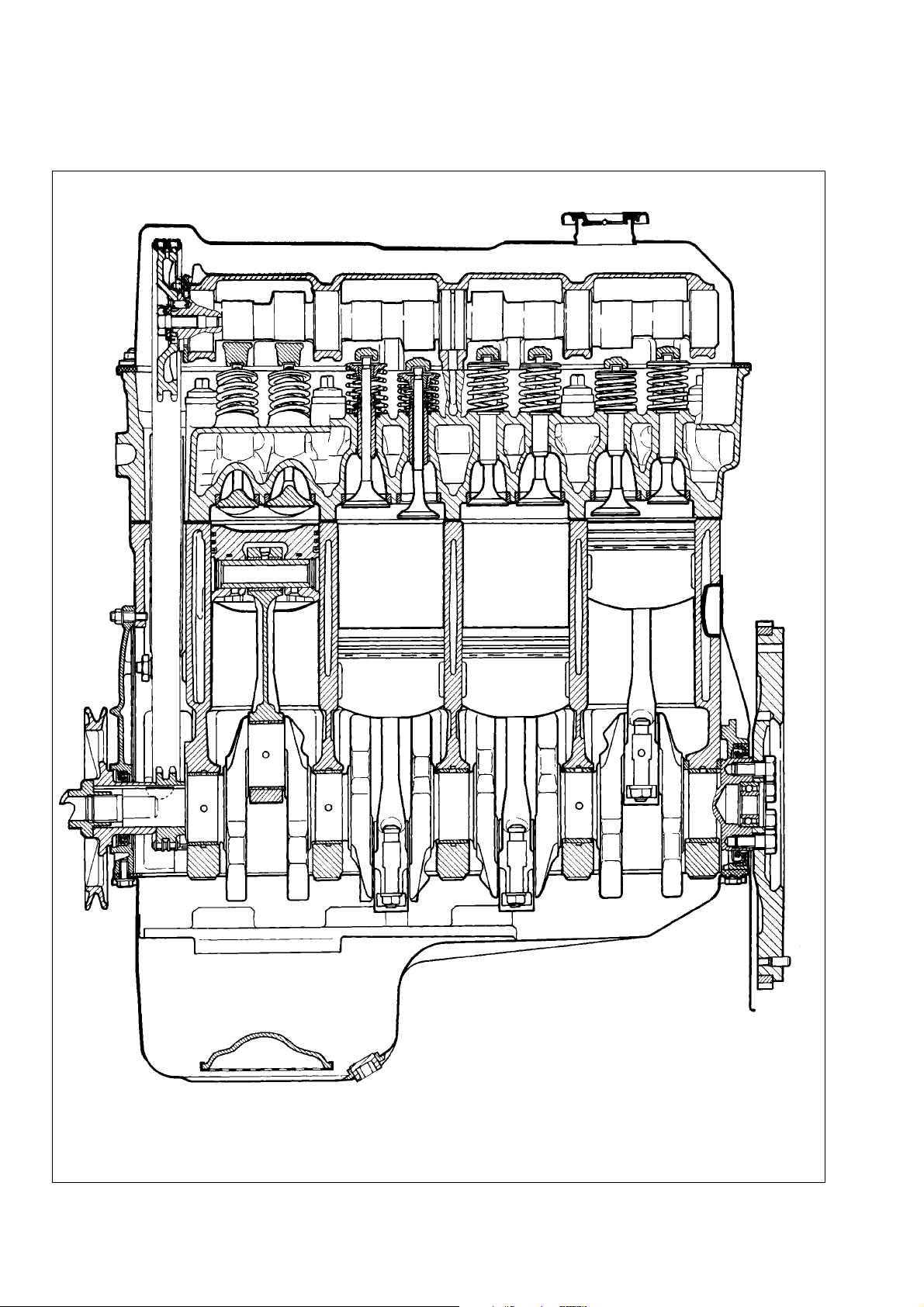
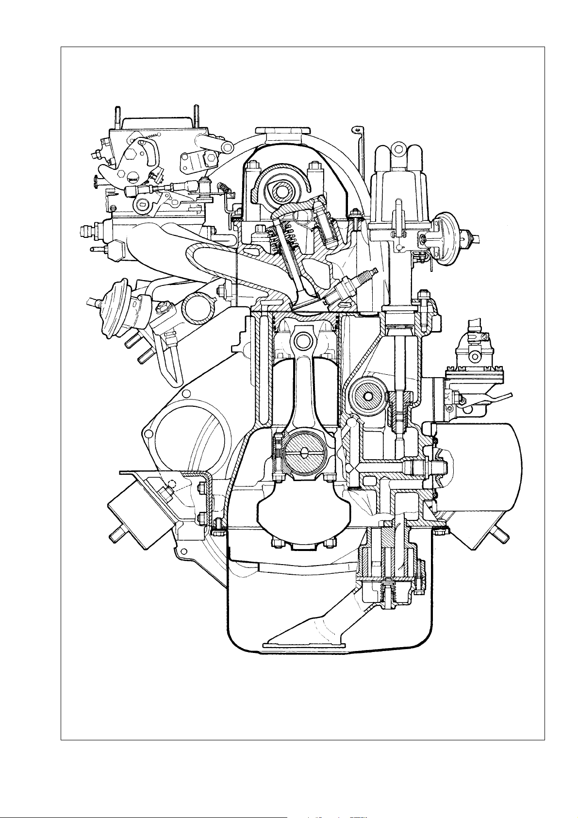
Refer to Fig.2-1 and Fig.2-2 for front and side sectional views of the engine.
7
Fig.2-1. Side sectional view of the engine
Page 8
8
Fig.2-2. Front sectional view of the engine
Page 9

Fault diagnosis
Symptom/fault Remedy
Engine fails to start
1. No fuel to carburettor:
- blocked fuel pipes or fuel filter;
- clogged carburettor or fuel pump filters;
- faulty fuel pump
2. Ignition system fault
3. Carburettor fuel cutoff solenoid fails to open at ignition switch-on:
- disconnected, loose or broken wiring to solenoid or solenoid control
unit;
- faulty solenoid control unit;
- defective fuel cutoff solenoid
4. Carburettor choke not opening at first flashes in cylinders
Engine idles erratically or stalls
1. Incorrectly adjusted idle speed
2. Defective carburettor solenoid control system
3. Faulty carburettor:
- blocked carburettor jets or internal passages;
- water in carburettor;
- broken choke control diaphragm
4. Ignition system fault
5. Vacuum leak through damaged hose between intake pipe and brake
servo unit
6. Air leak through gaskets at connections between intake pipe and carburettor/cylinder head
7. Leaking distributor vacuum pipe
Engine lacks power and has poor acceleration
1. Partly open throttle
2. Choked air cleaner element
3. Ignition system fault
4. Faulty fuel pump
5. Faulty carburettor:
- faulty accelerator pump;
- blocked main jets;
- partly open choke;
- low fuel level in float chamber;
- leaky throttle enrichment diaphragm
6. Restricted fuel tank vent pipe
7. Incorrect valve clearances
8. Misaligned timing marks
9. Insufficient cylinder compression - below 1 åP‡ (10 kgf/Òm
2
):
- broken or sticking piston rings;
- poor valve-to-seat fitting;
- excessively worn cylinders or piston rings
9
1. Carry out the following operations:
- blow fuel pipes, clean fuel tank, renew fuel filter;
- clean filters;
- check pump operation and renew any damaged components
2. Refer to section «Ignition system»
3. Carry out the following:
- check wiring and connections, renew damaged wires;
- renew control unit;
- replace solenoid with a new one
4. Eliminate any leakage of choke pull-down unit
1. Adjust idle speed
2. Refer to «Engine fails to start»
3. Carry out the following:
- blow carburettor jets and internal passages;
- remove water from carburettor, drain sludge from fuel tank;
- fit new diagram
4. Refer to section «Ignition system»
5. Replace damaged hose
6. Tighten retaining nuts or renew gaskets; eliminate carburettor flange
deformation or fit new carburettor
7. Fit new pipe in place of damaged one
1. Adjust throttle linkage
2. Change filter element
3. Refer to section «Ignition system»
4. Check pump operation and renew any damaged components
5. Carry out the following:
- check pump operation, renew damaged parts;
- blow jets with compressed air;
- adjust choke operation;
- adjust float;
- replace diaphragm
6. Blow pipe with compressed air
7. Adjust valve clearances
8. Adjust timing belt accordingly, align timing marks
9. Carry out the following:
- clean piston rings or grooves from carbon deposits, renew damaged components;
- replace damaged valves, regrind valve seats;
- replace pistons, rebore and hone cylinders.
Page 10

Main bearing knocking
Typical knocking or thumping noticeable at sudden throttle opening at idle which intensifies with higher crankshaft rate. Excessive endfloat
of crankshaft causes sharper irregular knocking, especially noticeable during smooth increase or decrease in crankshaft speed.
1. Early ignition
2. Insufficient pressure oil
3. Loose flywheel securing bolts
4. Excessive main bearing running clearance
5. Excessive thrust washers-to-crankshaft clearance
Big-end bearing knocking
Big-end bearing knocking is sharper than that of main bearings. It is noticeable during engine idle at sudden throttle opening. The origin of
knocking can be easily identified through switching off spark plugs one at a time.
1. Insufficient oil pressure
2. Excessive big-end bearing running clearance
Piston slap
Thumping noise caused by piston «runout» in cylinder. Most noticeable at low crankshaft speed and under load.
1. Excessive piston-to-cylinder bore clearance
2. Excessive gudgeon pin-to-piston groove clearance
Knocking of intake or exhaust valves
Excessive valve clearances cause typical regular noise; its frequency is lower than the frequency of any other engine noise, since the valves
are operated by camshaft rotating at half the crankshaft speed.
1. Excessive valve clearances
2. Broken valve spring
3. Excessive valve-to-guide clearance
4. Worn camshaft lobes
5. Loose locknut of adjuster bolt
Excessive noise of camshaft operation line
Noise from camshaft operation line is caused by clearances between engagement elements and becomes noticeable in general engine noise
at low crankshaft speed.
1. Loose chain caused by general wear
2. Broken chain tensioner shoe or damper
3. Seized chain tensioner plunger rod
Insufficient oil pressure at warm engine idle
1. Foreign particles entrapped under oil pump relief valve
2. Seized oil pressure relief valve
3. Worn oil pump gears
4. Excessive main bearing running clearance
5. Excessive camshaft bearing journal-to-bearing housing clearance
6. Incorrect oil grade or inappropriate oil quality
Excessive oil pressure on warm engine
1. Seized oil pressure relief valve
2. Excessively tough spring of oil pressure relief valve
10
1. Adjust ignition timing
2. Refer to subsection «Insufficient oil pressure at idle»
3. Tighten bolts to torque specified
4. Grind journals and renew bearing shells
5. Fit new thrust washers, check clearance
1. Renew valve
2. Renew spring
1. Refer to «Insufficient oil pressure at idle»
2. Fit new bearing shells and regrind journals
1. Adjust clearances
2. Renew spring
3. Replace worn parts
4. Renew camshaft and levers
5. Adjust clearance between lever and cam, tighten locknut
1. Renew pistons, rebore and hone cylinders
2. Fit new rings or new pistons with rings
1. Tighten chain
2. Renew tensioner shoe or damper
3. Eliminate seizure
1. Clean valve from foreign particles and flash, clean oil pump
2. Renew valve
3. Repair oil pump
4. Turn journals and renew bearing shells
5. Renew camshaft or bearing housing
6. Change oil as recommended in Attachment 4
Page 11

Excessive oil consumption
1. Oil leaking through engine gaskets
2. Restricted crankcase ventilation system
3. Worn piston rings
4. Broken piston rings
5. Foul windows of oil scraper rings or foul slots in piston grooves due to
wrong oil
6. Worn or damaged valve oil caps
7. Badly worn valve stems or guides
Excessive fuel consumption
1. Choke not fully opened
2. Excessive resistance to vehicle motion
3. Incorrect ignition timing
4. Defective distributor vacuum unit
5. High fuel level in carburettor:
- leaking needle valve or its gasket;
- seizure or excessive friction hindering normal float operation
6. Choked carburettor air jets
7. Leaking part throttle enrichment diaphragm
8. Carburettor solenoid failed to shut off fuel at overrun:
- no earthing of idle switch sliding contact;
- broken wire between control module and carburettor idle switch;
- faulty control module
Engine overheating
Coolant temperature gauge needle is in the red sector. Start tracing the failure with checking coolant temperature gauge and its sender (Refer
to section «Instrumentation»).
1. Slackened pump and alternator drive belt
2. Insufficient coolant in system
3. Incorrect ignition timing
4. Dirty radiator outside
5. Defective thermostat
6. Faulty radiator cap inlet valve (opening pressure is below 0.07 MPa
(0.7 kgf/cm
2
)
7. Defective coolant pump
Sudden coolant drop in expansion tank
1. Damaged radiator
2. Damaged cooling hoses or pipe gaskets, loose clips
3. Leaking heater tap or heater matrix
4. Leaking water pump seal
5. Damaged radiator cap or cap seal
6. Defective cylinder head gasket
7. Leaks from fissures in cylinder block or cylinder head
8. Leaks from fissures in water pump housing, water jacket return pipe,
thermostat, expansion tank or intake pipe
11
1. Tighten fittings or replace gaskets and oil seals
2. Wash components of crankcase ventilation system
3. Rebore and renew pistons and rings
4. Renew rings
5. Clean windows and slots of carbon, change motor oil as recommended in
Attachment 4
6. Renew oil caps
7. Renew valves, repair cylinder head
1. Adjust choke linkage
2. Check and adjust pressures in tyres, braking system, wheel alignment
3. Adjust ignition timing
4. Renew vacuum unit or ignition distributor
5. Carry out the following:
- check for any foreign matter entrapped between needle and valve seat;
renew valve or gasket as applicable;
- check and when necessary replace floats
6. Clean jets
7. Replace diaphragm
8. Following to be done:
- clean solenoid contact surfaces;
- check wiring and connections, renew damaged wire;
- renew control unit
1. Adjust drive belt tension
2. Top up coolant to cooling system
3. Adjust ignition timing
4. Clean radiator outside with water jet
5. Renew thermostat
6. Renew cap
7. Check pump operation, renew or repair pump
1. Repair or renew radiator
2. Renew damaged hoses or gaskets, tighten hose clips
3. Renew tap or heater matrix
4. Renew seal
5. Renew cap
6. Renew gasket
7. Check cylinder block and cylinder head for leakage; renew damaged components in case of evident cracking
8. Check for leaks; renew components in case of fissures; minor leaks can
be cured by adding a radiator sealant such as заалл-1
Page 12
Engine - removal and refitting
Put the vehicle on a lift or over an inspection pit and apply the
handbrake. Take out the spare wheel and its supporting pipe.
Disconnect the battery leads and withdraw the battery. Unbolt
and remove the bonnet.
To remove the air cleaner, disconnect its hoses, remove the
cover and filter element. Temporarily plug the carburettor.
Disconnect the throttle linkage and choke cable.
Disconnect the wires from the fuel cutoff solenoid, idle switch,
oil pressure sensor, coolant temperature sensor, ignition distributor, alternator and starter motor.
Drain coolant from the radiator, cylinder head and heater unit.
To do this, shift the heater tap control lever to the right, undo the
caps on the cylinder block left side and radiator right-hand fluid
cooler, screw instead the return hoses connectors, then undo the
caps of the expansion tank and radiator.
Separate the fan cowl halves and remove the fan blower
cowl. Disconnect the coolant supply and return hoses from the
engine. Undo two bolts retaining the radiator to the body, release
the top catch of the fan cowl, move the top radiator toward the
engine and withdraw the radiator from the engine bay complete
with the thermostat and associated hoses. Remove the fan cowl.
Undo the nuts holding the downpipe to exhaust manifold.
Detach the downpipe from the bracket on the transmission and
lower it down.
Slacken the clips, disconnect the hoses from the fuel pump and
secure the pump in the position that excludes any fuel leakage.
Detach the fuel return hose from the carburettor.
Release the clips and disconnect the hoses from the heater
manifolds, detach the brake servo hose from the intake pipe.
Use socket spanner 02.7812.9500 to unbolt the starter motor
from the clutch housing. Undo the bolts holding the clutch housing cover to the lower clutch. Using Ä.55035 undo the clutch bellhousing to the cylinder block.
Hoist the beam íëé-3/379 and secure the engine right side
to the lifting yoke at the front exhaust manifold stud, while the left
side shall be secured through the clutch housing mounting hole.
Slightly tension the hoist, undo the nuts that retain front
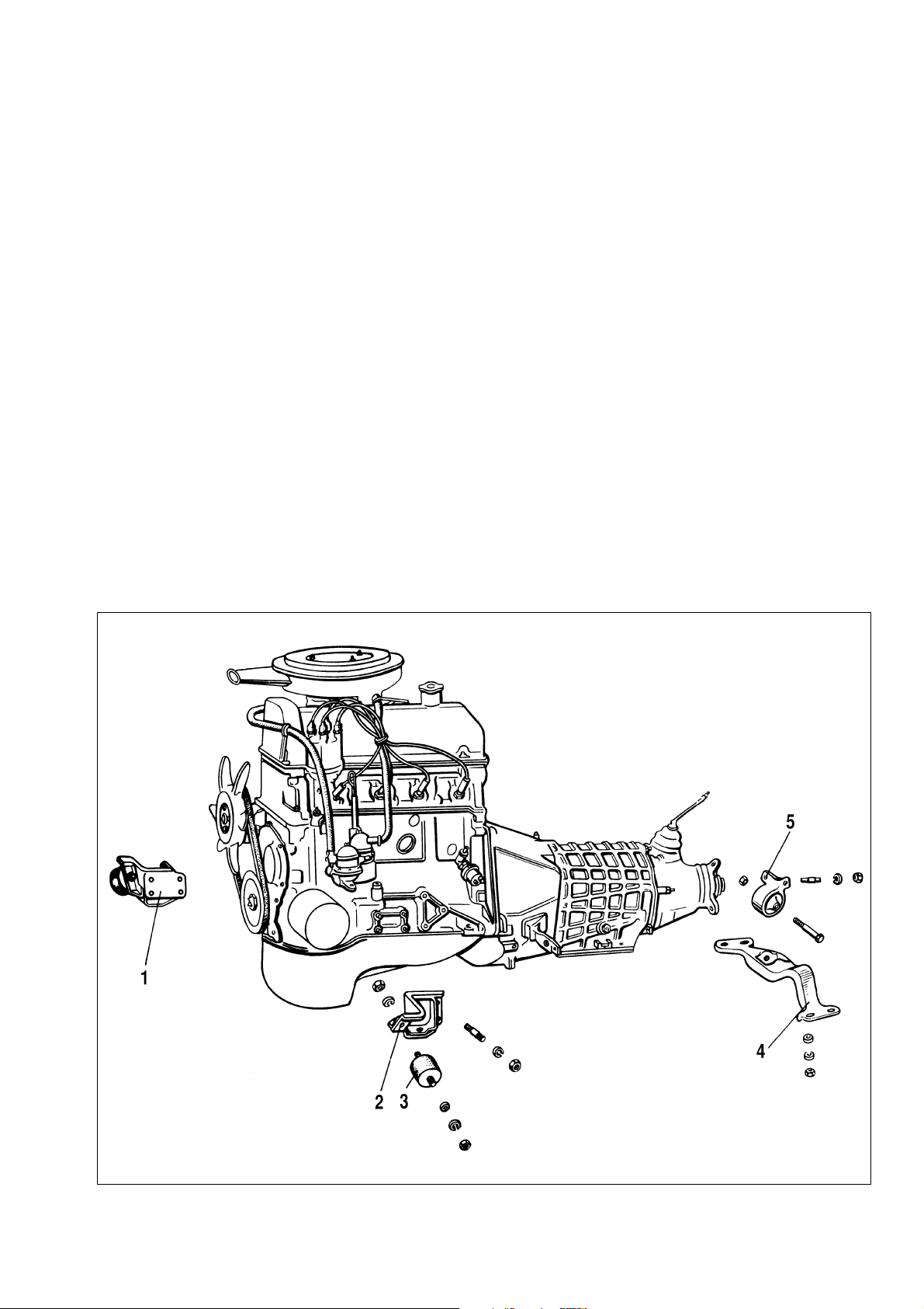
engine mounting rubbers 3 (Fig.2-3) to the side brackets, undo
the nut and bolt holding the front axle housing to the engine
brackets. Disconnect the engine negative lead.
Lift out the engine, first raise its top in order to take the bolts
of the mounting rubber out of the bracket holes, then move the
engine forward in order to release the input shaft from the bearing in the crankshaft flange.
12
Fig. 2-3. Engine mounting unit:
1 - right-hand support bracket with rubber; 2 - left-hand support bracket; 3 - mounting rubber; 4 - cross-piece, rear mounting; 5 - bracket with rear mounting
Page 13
Remove the starter motor heat shield, followed by the starter
motor, hot air intake complete with the supply hose. Remove from
the cylinder head two side brackets together with the front engine
mounting rubbers.
Unbolt the clutch and withdraw it.
Refitting is a reversal of the removal procedure. Draw special
attention to the engine-to-transmission connection: the input shaft
must precisely engage the clutch disc splines. Furthermore, for
perfect engine/transfer box centering, the centering washers of
the front engine mounting rubbers must be in the respective side
brackets holes.
Engine - dismantling
Flush the engine, mount it on a stand for dismantling and
drain the oil sump.
Remove the carburettor, for that disconnect the hoses and
throttle operating rod.
Remove the fuel pump and ignition distributor. Use spanner
67.7812.9514 to unscrew the spark plugs and coolant temperature sensor.
Remove the alternator and water pump drivebelt. Remove the
alternator and its retaining bracket.
On the pump and exhaust manifold disconnect the coolant
supply pipe from the heater.
From the pump and exhaust manifold disconnect the coolant
supply pipe from the heater.
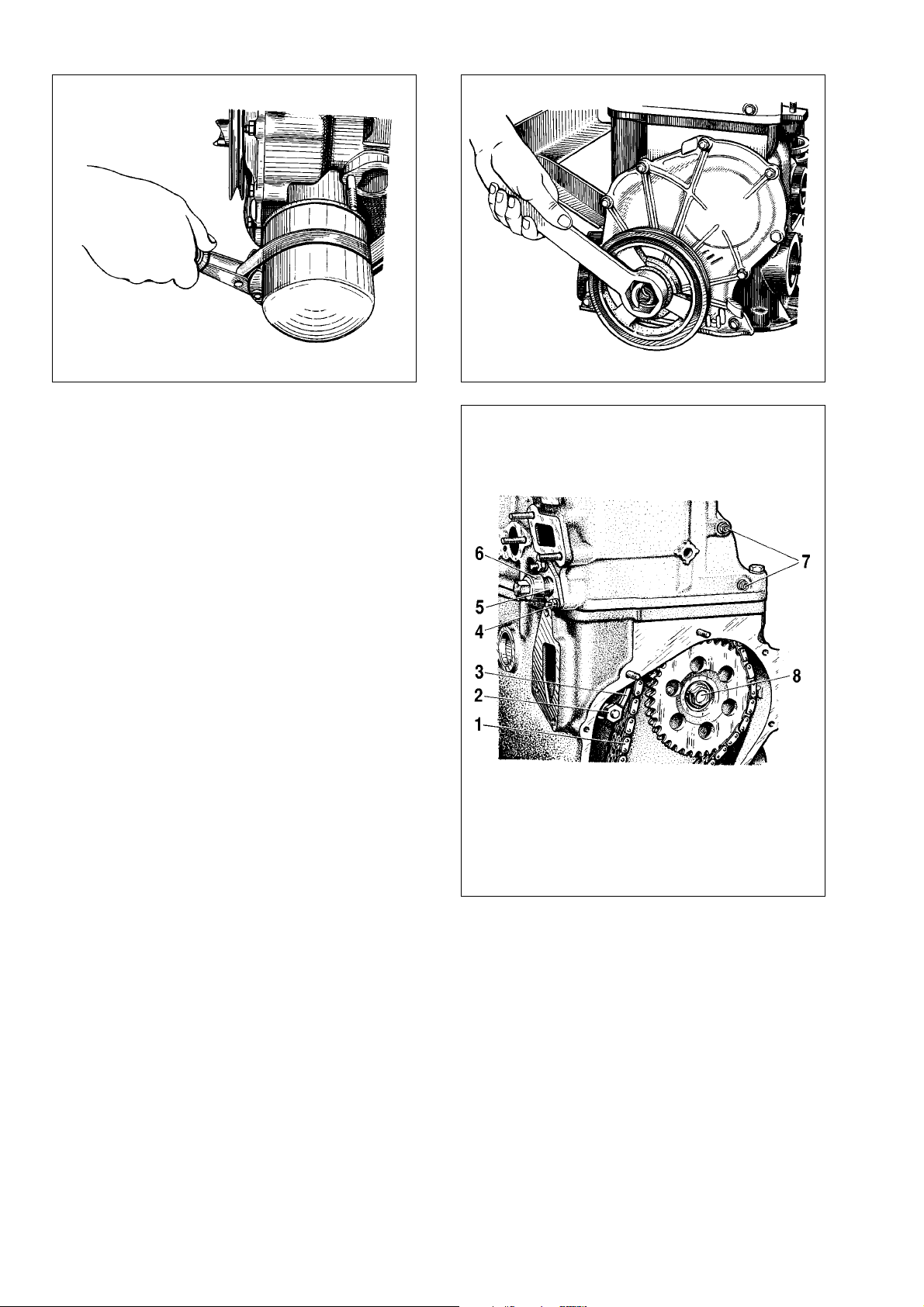
Use tool Ä.60312 to undo the oil filter with seal, remove the
oil filter and seal (Fig.2-4).
Unscrew the oil pressure warning lamp sender. Remove the
crankcase vent breather cover, crankcase and oil pump. Remove
the oil separator drain pipe catch and take out the oil separator.
To remove the crankshaft pulley, secure the flywheel using
Ä.60330/R (Fig. 2-10) and undo the nut using tool Ä.5012 (Fig. 2-
5). Withdraw the valve cover and timing cover. Unbolt the
camshaft and oil pump drive shaft sprockets.
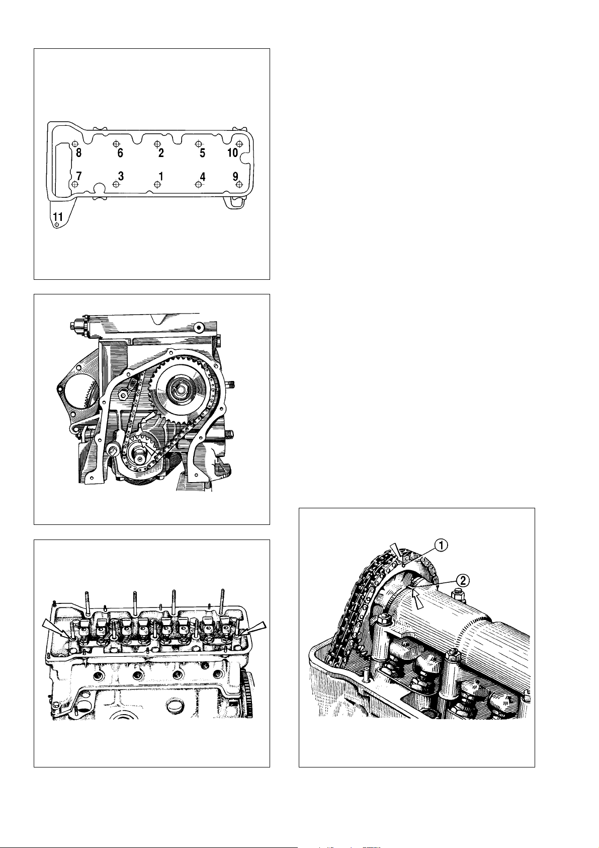
Slacken chain tensioner cap nut 6 (Fig.2-6), undo nut 4 holding it to the cylinder head, remove the tensioner; then unbolt and
remove chain tensioner shoe 3.
Undo the chain stop pin, remove the oil pump and camshaft
sprockets, then take off the chain.
Loosen studs 4 nuts (Fig. 2-7). Remove the camshaft bearing
housing. Undo studs 4 nuts, remove thrust flange 1 and withdraw
the camshaft exercising maximum care not to damage the
camshaft bearing housing surface.
Unbolt the cylinder head and withdraw it complete with the
exhaust manifold and intake pipe.
13
Fig.2-4. Removing the oil filter using tool Ä.60312
Fig.2-5. Releasing the crankshaft nut using tool Ä.50121
Fig.2-6. Removing the chain tensioner and damper:
1 - camshaft timing chain; 2 - shoe retaining bolt; 3 - tensioner chain; 4 - tensioner retainer nut; 5 - tensioner housing; 6 - tensioner cap nut; 7 - chain
damper securing bolts; 8 - oil pump shaft sprocket retaining bolt
Page 14
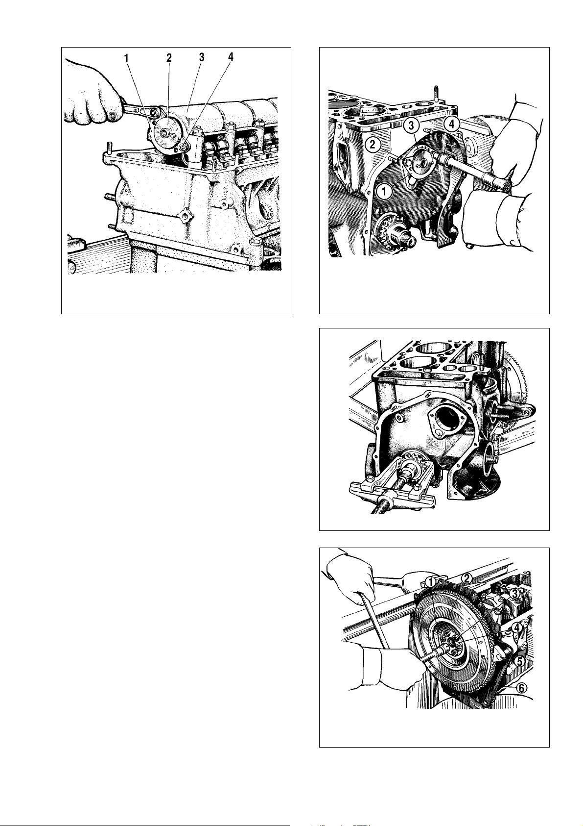
Remove thrust flange 1 (Fig.2-8) of the oil pump drive shaft
and take the shaft out of the cylinder block.
Using picker Ä.40005/1/7 (kit Ä.40005) drive the sprocket off
the crankshaft (Fig.2-9).
Undo the connecting rod bolts, remove the big end cap and
carefully lift the pistons with the conrods through the cylinders.
Mark the piston, connecting rod, main and big-end bearing shells
for position to facilitate the reassembly.
WARNING. When removing the pistons and conrods, do
not press out the connecting rod bolts.
Fit tool 5 (Fig.2-10), undo bolts 3, remove washer 4 and the
flywheel from the crankshaft. Remove the front clutch housing
cover.
Using tool Ä.40006, take the input shaft bearing out from the
crankshaft (Fig.2-11).
Remove the crankshaft oil seal retainer.
Unbolt the main bearing cap bolts, remove them complete
with the lower bearing shells, then lift out the crankshaft, top
bearing shells and rear bearing thrust washers.
Engine - reassembly
Follow the engine reassembly procedure as below:
Locate a clean cylinder block and screw in any missing dowels. Oil the crankshaft bearing shells, thrust washers, pistons and
oil seals. Always fit new crankshaft oil seals when reassembling
the engine after overhaul.
14
Fig.2-7. Removing the camshaft thrust flange:
1 - thrust flange; 2 - camshaft; 3 - bearing housing; 4 - thrust flange securing
stud
Fig.2-8. Removing the oil pump shaft:
1 - thrust flange; 2 - flange securing bolt; 3 - oil pump shaft; 4 - wrench
Fig.2-10. Removing the flywheel:
1 - wrench; 2 - flywheel; 3 - flywheel securing bolt; 4 - washer; 5 - tool
Ä.60330/R to lock the flywheel stationary; 6 - front clutch housing cover
Fig. 2-9. Removing the crankshaft sprocket using a picker
Page 15
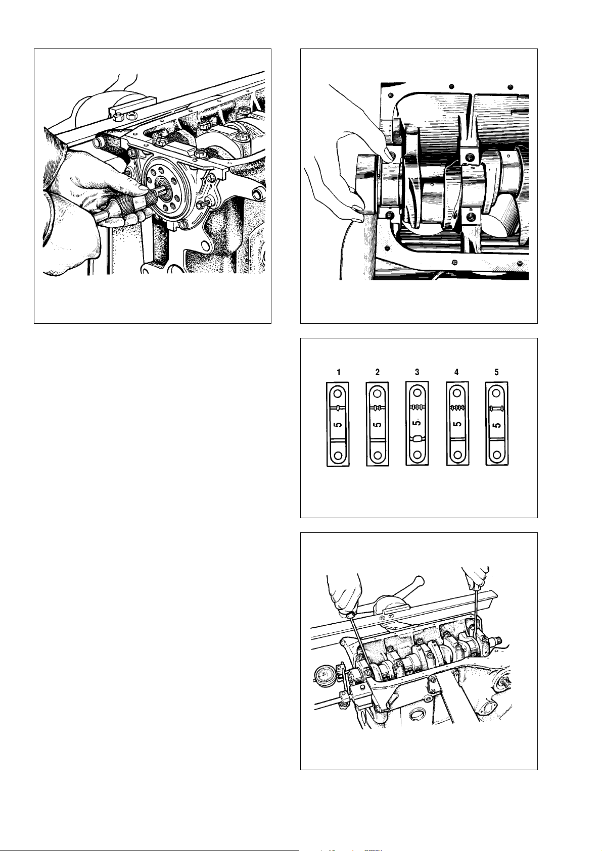
Fit the centre main bearing shells without an oilway into the
bearing recesses. Fit into other cylinder bores the bearing shells
with an oilway, while into the relevant main bearing caps - the
bearing shells without an oilway. Lower the crankshaft into position, then stick two thrust washers into the rear bearing recesses
(Fig.2-12).
WARNING. The washers must be fitted so that their oilways face away from the bearings in the block and cap (antifriction coat is applied on the washer surface). At the rear of
the rear main bearing there fitted a sintered thrust washer
(yellow), while at the front - a steel-aluminium thrust washer.
Locate the main bearing caps according to the marks on their
outer surface (Fig.2-13). Tighten the cap securing bolts.
Check the crankshaft endfloat. To do this, turn the cylinder
block to have the rear side up and position the dial gauge foot
against the crankshaft flange (Refer to Fig.2-14). Moving the
crankshaft up and down (using screwdrivers, for instance), check
the crankshaft endfloat to be within 0.06-0.26 ÏÏ. If not, adjust
accordingly and replace the old thrust washers with new ones or
fit thicker thrust washers.
Locate the rear oil seal housing gasket on the crankshaft
flange, insert the front clutch housing cover bolts into the respective bores (Fig.2-15). Place the oil seal housing on tool
41.7853.4011 and slide it to on the crankshaft flange; next secure
it to the cylinder block with the bolts.
Locate front clutch housing cover 6 (Fig.2-10) over two centering pins (Fig. 2-16). Secure the cover to the rear oil seal housing with nuts.
15
Fig.2-11. Pressing out the bearing from the crankshaft using tool A.40006 Fig. 2-12. Refitting the thrust washers to the rear mounting
Fig.2-13. Marks on the main bearing caps (bearing are numbered from the
engine front end)
Fig.2-14. Checking the crankshaft endfloat
Page 16
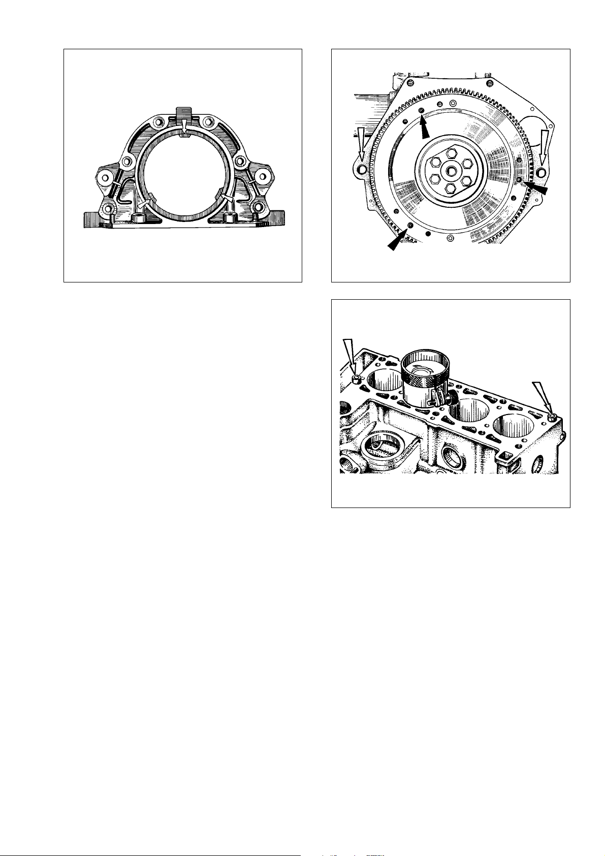
Locate the flywheel in position so that the marking (a cut-out)
near the rim is against the No 4 cylinder crankpin axis. While
holding the flywheel stationary with tool Ä.60330/R, bolt it to the
crankshaft flange to the specified torque.
Using a ring compressor (tool 67.8125.9502), fit the pistons
and connecting rods to the cylinders (Fig.2-17).
WARNING. The hole for gudgeon pin in the piston is 1.2
mm set off, so the arrows on the piston crown must face the
timing belt end of the engine when inserting the pistons into
the cylinders.
Press the big-end bearing shells into the connecting rods and
caps. Guide the conrods and big-end caps onto the crankshaft
journal, then tighten the connecting rod bolts. The big-end caps
must be positioned so that the cylinder number on the cap is
against the cylinder number on the connecting rod big-end.
Refit the crankshaft sprocket. Locate the oil pump shaft and
secure it with the thrust flange.
Insert two centering pins into the cylinder block (Fig.2-17) and
locate the cylinder head gasket over them.
WARNING. Always fit the new cylinder head gasket.
Never re-use the old gasket.
Before refitting the gasket, remove any oil from the mating surfaces of the block and cylinder head. Make sure the
gasket is perfectly clean and dry. Avoid any incidental oiling
of the gasket.
Turn the crankshaft so that the pistons are midway in the
cylinder bore.
Refit the cylinder head complete with the valves, exhaust
manifold and intake pipe over the centering pins.
Tighten the cylinder head bolts in the established procedure
(Fig.2-18) in four steps to ensure a reliable fit and exclude further
tightening during vehicle servicing.
1st step - tighten the bolts 1-10 to 20 N•m(2 kgf•m);
2nd step - tighten the bolts 1-10 to 69.4-85.7 N•m
(7.1-8.7 kgf•m), while the bolt 11 to 31.36 -
39.1 N•m (3.2-3.99 kgf•m);
3rd step - turn the bolts 1-10 to 90°;
4th step - turn again all bolts 1-10 to further 90°.
WARNING. The cylinder head bolts can be re-used only
when their length is not in excess of 120 mm, otherwise
renew the bolt.
Before reassembly, immerse the bolts, thread and head,
into engine oil. Allow the excess oil drip for at least 30 minutes. Remove all entrapped oil from the bolt bores in the
cylinder head.
16
Fig.2-15. Crankshaft rear oil seal housing.
The lugs (arrowed) for centering the housing against the crankshaft flange
Fig.2-17. Fitting the pistons complete with piston rings using ring compressor; centering pins of the cylinder head (arrowed)
Fig.2-16. Clutch dowels (arrowed black) and clutch housing centering
pins (arrowed white)
Page 17
Turn the flywheel so that the mark on the crankshaft sprock-
et is against the cylinder block mark (Fig.2-19).
Check to see the camshaft bearing housing centering pins
are in position (Fig.2-20). Refit the sprocket to the camshaft complete with the bearing housing and turn the camshaft so that the
timing mark in the sprocket is aligned against the mark on the
bearing housing (Fig.2-21). Remove the sprocket and without
changing the camshaft position, refit the bearing housing to the
cylinder head so that the centering pins are in the respective
bores of the bearing housing. Secure the bearing housing, tightening the nuts in the sequence as shown in Fig.2-22.
Refit the chain vibration damper.
Refit the camshaft timing chain:
- fit the chain onto the camshaft sprocket and position the
sprocket so its TDC mark is aligned with the respective mark on
the bearing housing (Fig.2-21). Do not tighten the sprocket bolt
fully;
- fit the sprocket to the oil pump shaft, but do not tighten the
retaining bolt fully;
- fit the chain tensioner shoe and tensioner, but do not tighten the cap nut so that the tensioner spring can compress the
shoe; screw the chain stop pin into the cylinder block;
- turn the crankshaft two turns forward to ensure the chain
tension required; check the indentations in the sprockets are
aligned with TDC marks in the cylinder block and bearing housing (Fig.2-19 and Fig.2-21);
- when the marks are aligned, hold the flywheel stationary
with tool Ä.60330/R (Fig.2-10), then tighten the sprocket securing
bolts and chain tensioner cap nut to the torques specified, bend
the sprocket bolt lock washers; should the marks are not aligned,
repeat the chain refitting procedure.
17
Fig. 2-18. Cylinder head bolt tightening sequence
Fig. 2-19. Aligning the timing marks on the crankshaft sprocket and cylin-
der block
Fig.2-20. Centering pins for camshaft bearing housing
Fig.2-21. Aligning the timing mark on the camshaft sprocket against bearing housing mark:
1 - mark in sprocket; 2 - mark on bearing housing
Page 18
Adjust the clearance between the camshaft lobes and valve
levers.
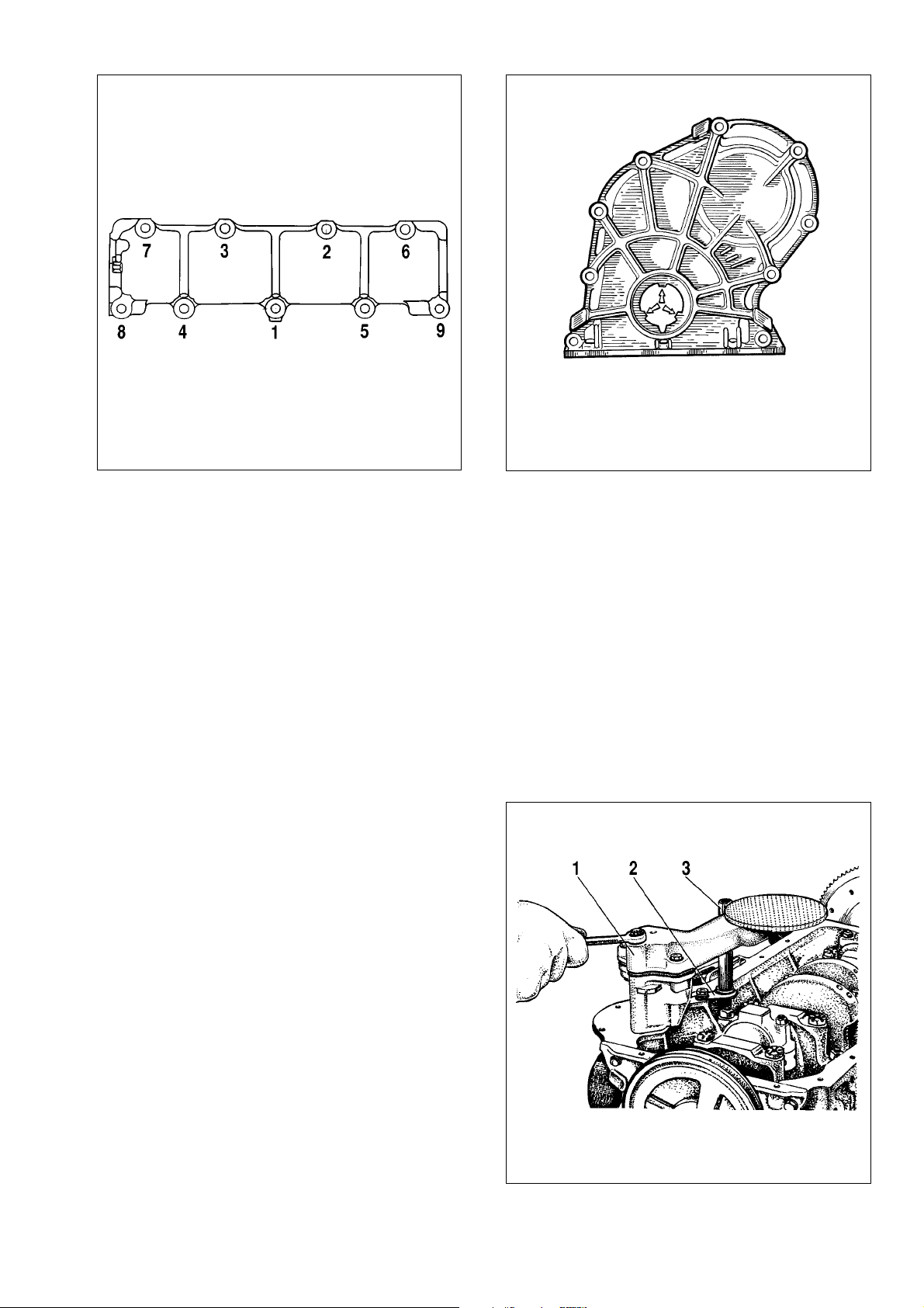
Refit the camshaft cover (Fig.2-23) complete with the gasket
and oil seal to the cylinder block, do not tighten the retaining bolts
and nuts fully. Using tool 41.7853.4010 centralize the cover
against the crankshaft end, then tighten the retaining nuts and
bolts to the torques specified.
Fit the alternator and oil pump pulley, then secure it with the
nut.
Fit the oil filter complete with the gasket, manually screw it to
the union on the cylinder block. Refit the crankcase vent oil separator, breather cover and secure the oil separator drain pipe with
the clip.
Fit oil pump 1(Fig.2-24), then fit the oil sump with the gasket.
Fit the coolant pump, alternator bracket and alternator. Fit the
belt around the pulleys and adjust the belt tension.
Fit the heater matrix supply pipe and cooling water jacket outlet pipe to the cylinder block. Secure the heater matrix drain pipe
to the coolant pump and outlet pipe.
Fit the instrumentation sensors.
Fit the oil pump / distributor gear, followed by the ignition distributor. Insert the spark plugs, place spanner 67.7812.9515 on
the spark plugs and tighten the spark plugs with a torque wrench
to the torques specified.
Fit the fuel pump as outlined in section «Fuel system».
Fit the carburettor and reconnect the hoses. Cover the carburettor with a provisional cap.
WARNING. Never secure the carburettor (or tighten its
retaining nuts) when it is warm.
Fit the valve cover complete with the gasket and fuel piping
bracket.
Fit the air cleaner, to do this secure the hoses to the air cleaner housing, fit the filter housing complete with the gasket to the
carburettor, then fit the mounting plate and secure the housing
with nuts. Locate the filter element and secure the air cleaner
cover.
Reconnect the HT leads to the distributor and spark plugs.
Fill the engine with motor oil through the oil filler in the valve
cover.
18
Fig.2-22. Camshaft bearing housing nuts tightening sequence
Fig.2-24. Refitting the oil pump:
1 - oil pump; 2 - drain pipe lock; 3 - oil separator drain pipe
Fig.2-23. Timing cover
Projections (arrowed) for cover centering against crankshaft pulley hub
Page 19

Engine run-in after overhaul
After overhaul the engine is bench tested (run-in) at no loads
under the following cycle:
750-800 rpm 2 minutes
1000 rpm 3 minutes
1500 rpm 4 minutes
2000 rpm 5 minutes
Locate the engine on the test bench, start the engine and
make checks with respect to the following items:
- evidence of coolant or fuel leaks through mating compo-
nents, pipe connections or gaskets;
- oil pressure and oil leaks through gaskets;
- ignition timing;
- idle speed;
- carburettor / intake pipe tightness;
- abnormal knock.
In case of any malfunctions or unknown rattle, stop the
engine, eliminate the faults, then continue the tests.
In case of oil leaks through the gasket between the valve
cover and cylinder head or through the gaskets between the oil
sump, cylinder block and covers, tighten the securing bolts to the
torque specified. If oil leaks persist, check the correct fitting of the
gaskets and renew when applicable.
Since the overhauled engine is not fully bed-in and frictions
between the working surfaces of renewed parts show significant
resistance to the rotation, a certain run-in period is required.
This especially concerns those engines, where the pistons,
main / big-end bearing shells have been renewed, or the crankshaft journals have been reground, or the cylinders - honed.
Therefore during run-in after the engine overhaul, never allow
the engine to run at maximum loads. When in the vehicle, always
run-in the engine at the speeds which are recommended for the
run-in periods.
In-vehicle engine inspection after overhaul
Locate the engine in the vehicle, thoroughly check its correct
mounting.
Run the engine for a while, then check for:
- coolant or fuel leaks through pipe connections, tighten when
necessary;
- full throttle opening and closing by the carburettor cable,
adjust accordingly, if necessary;
- alternator drivebelt tension, adjust, when applicable;
- reliable wiring connections and operation of the warning
lamps in the instrument cluster.
WARNING. Never check the engine or vehicle on the
roller stand without additional rollers for the front wheels.
Cylinder block
General description
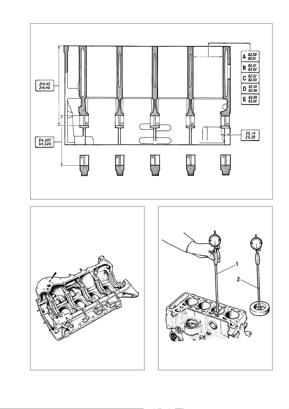
The cylinder block basic sizes are shown in Fig.2-25.
The cylinder block is of a low-alloyed cast iron. The cylinder
bores are of five classes in steps of 0.01 mm and are designated
by the letters A, B, ë, D, Ö. The cylinder class is engraved on the
cylinder block bottom face. (Fig.2-26).
The cylinders can be rebored to accommodate the oversize
pistons of 0.4 mm and 0.8 mm bigger diameters.
The main bearing caps are machined complete with the cylinder block; therefore they are not interchangeable and feature distinctive notches on the outside surface (Fig.2-13).
Inspection and repair
Inspection. Wash the cylinder block thoroughly and clear the oilways. Blow dry with compressed air and inspect the cylinder
block visually. Make sure there are no cracks in the mountings or
elsewhere in the cylinder block.
When cooling water is suspected in the crankcase, use a
special test bench to examine the cylinder block for leaks. To do
this, plug the cylinder block cooling water jacket ports, force in
some room temperature water at 0.3 MPa (3 kgf/sq.cm). There
should be no evidence of water leaks from the cylinder block within 2 minutes.
When coolant is found contaminated with oil, do not strip the
engine completely, rather check the cylinder block for cracks in
the area of the oilways. For that, drain the coolant from the cooling system, remove the cylinder head, refill the cylinder block
water jacket with water and apply compressed air to the vertical
oilway in the cylinder. If there are any bubbles in the water of the
cooling water jacket, renew the cylinder block.
Examine the split face between the cylinder block and cylinder head using a straight-edge and feeler blades. Position the
straight-edge diagonally and using a feeler gauge measure at the
centre, both transversely and longitudinally. The flatness to be
within 0.1 mm tolerance.
Cylinder repair. Check the cylinders for wear to be maximum
0.15 mm.
When available, use a dial inside gauge to measure the bore
diameter (Fig.2-27) in four lands, both longitudinally and transversely (Fig.2-28). Use tool 67.8125.9502 to set the inside gauge
to zero.
19
Page 20
20
Fig.2-26. Cylinder size class engraved on the cylinder block
Fig.2-27. Measuring the cylinder bore with the inside dial gauge:
1 - inside dial gauge; 2 - setting to zero against reference gauge
Fig.2-25. Basic sizes of the cylinder block
Page 21
There is practically no wear in the land 1 area of the cylinders. Compare the values measured on the first and other cylinder lands to see the amount of the cylinder wear.
When the maximum wear is over 0.15 mm, rebore the cylinders to the nearest oversize; provide 0.03 mm honing allowance
on the diameter. Hone the cylinder walls so that the difference
between the oversize piston diameter and cylinder bore is 0.025
- 0.045 mm.
Pistons and connecting rods
General Description
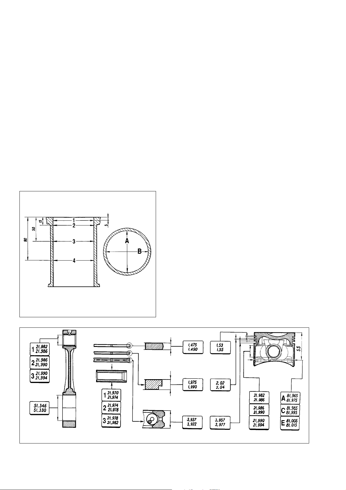
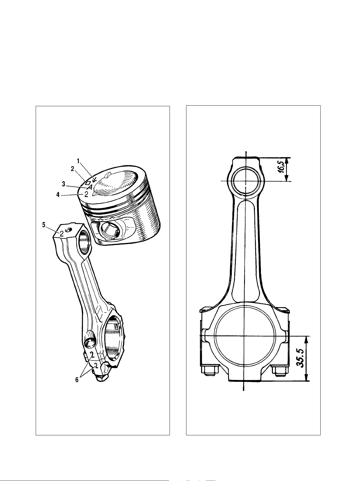
The basic sizes of the pistons and connecting rods are
shown in Fig.2-29.
Piston is an aluminium casting. The piston weight is
precisely maintained during the manufacturing process.
Consequently, there is no need to select the matching piston of
the same weight class during the engine assembly.
There are five classes (Ä, Ç, ë, D, Ö) of the piston according
to their major diameter, in steps of 0.01 mm. The piston has a
complex outside shape: tapered in height and oval in the crosssection area. Therefore, the piston diameter must be measured
in the plane normal to the gudgeon pin at 55 mm from the piston
crown.
There are three classes (1, 2, 3) of pistons, as to the hole for
the gudgeon pin, in step of 0.004 mm. The classes of piston
diameters and holes for the gudgeon pin are stamped on the piston crown (Fig.2-30).
The oversize piston major diameter is 0.4 or 0.8 mm bigger.
The 0.4 step is marked in the form of a triangle, while the 0.8 mm
step is marked as a square.
Use the arrow on the piston crown for correct piston orientation and fitting within the cylinder. The arrow of the piston must
face the timing belt end of the engine.
Gudgeon pin is of steel, hollow, floating-type, i.e. freely
operates in the piston bosses and connecting rod bush. The gudgeon pin is secured in the hole with two circlips.
As to the outside diameter the gudgeon pin are of three
classes in step of 0.004 mm. The class is paint marked on the
gudgeon pin face: 1st class - blue paint, 2nd class - green paint,
3rd class - red paint.
Piston rings are of cast iron. The top compression ring has
a chromed barrel face. The bottom compression ring is of the
scraper type. The oil control piston ring features chromed working edges and has a coil expander (spreader ring).
The oversize rings are marked as 40 or 80, which corresponds respectively to 0.4 or 0.8 mm step in the major diameter.
Connecting rod is of forged steel.The connecting rod is
machined together with the big end cap, therefore they are interrelated. The cylinder number (6 in Fig.2-30) is stamped on the
caps and connecting rods to prevent confusion when refitting into
the cylinders. During reassembly the figures on the connecting
rod and cap should face the same side.
21
Fig.2-28. Measuring the cylinder bore:
A and B - direction of measurement; 1, 2, 3 and 4 - No of lands
Fig.2-29. Basic dimensions of pistons and connecting rods
Page 22
The connecting rod small-end features a pressed-in steelbronze bush. As to the diameter of the bush, the connecting rods
are divided into three classes in steps of 0.004 mm (similar to the
pistons).
The class number (5 in Fig.2-30) is engraved on the big-end
cap.
The connecting rod small-end and big-end are classified
weight-wise (Table 2-1) and are paint marked on the connecting
rod. The engine must always be fitted with the connecting rods of
the same weight class. The connecting rod weight can be adjusted by removing excess metal from the bosses on the small-end
or big-end up to the minimum size of 16.5 mm or 35.5 mm (Fig.2-
31).
22
Fig.2-30. Marking on the piston and connecting rod:
1 - arrow on piston crown for orientation in cylinder; 2 - oversize; 3 - piston class;
4 - class of gudgeon pin hole; 5 - connecting rod class as to gudgeon pin hole;
6 - cylinder No
Fig.2-31. Locations of possible metal removal subject to adjusted connecting rod small-end and big-end weights
Page 23
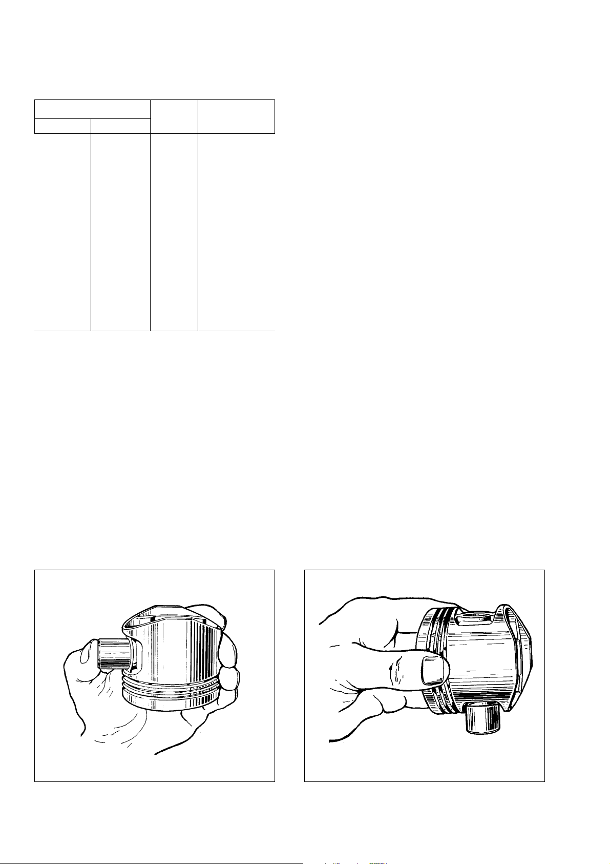
Table 2-1
Connecting rod classification as to
small-end and big-end weights
Connecting rod weight, g Class Paint mark
small-end big-end
519±3 Ä white
186±2 525±3 Ç blue
531±3 ë red
519±3 D black
190±2 525±3 E violet
531±3 F green
519±3 G yellow
194±2 525±3 ç brown
531±3 I orange
Selecting piston to cylinder
The design clearance between the piston and cylinder bore
(for new parts) is 0.025 - 0.045. The condition must be ensured
through prior measurements of the associated parts and fitting of
the pistons which belong to the same class of cylinders. The maximum permissible gap (for worn parts) is 0.15 mm.
When the engine, in the course of operation, shows a clearance of over 0.15 mm, reselect the pistons to the cylinders to
have the clearance as close to the design value as possible.
The pistons of classes Ä, ë, Ö are intended for replacement.
These classes can be selected to closely match any cylinder in
the event of the engine overhaul, since the pistons and cylinders
are classified with small overlapping in the sizes. It means, the
piston of class C can match the cylinders of class B and D.
Dismantling and reassembly
Dismantling. Prise out the gudgeon pin circlips from the pis-
ton, press out the gudgeon pin and detach the connecting rod
from the piston. Remove the piston rings.
The bolts are pressed into the connecting rod and must never
be pressed out from the connecting rods during the engine or piston/connecting rod dismantling.
When some components of the piston or connecting rod are
not damaged or show little wear, they can be re-used. Identify
them accordingly during dismantling to facilitate further reassembly with the respective components and to the original cylinder.
Reassembly. Before reassembly, select the gudgeon pin to
match the piston and connecting rod. For new components the
class of the holes for the gudgeon pin in the connecting rod and
pistons must be identical to the class of the gudgeon pin. In case
of used components, for perfect mating, the gudgeon pin when
oiled should fit the relevant piston hole by force of the hand thumb
(Fig.2-32); it should not drop out while held as shown in Fig.2-33.
If the gudgeon pin drops, replace it with a new one of the next
class. When the piston is fitted with the gudgeon pin of the third
class, renew the piston, gudgeon pin and connecting rod.
The reassembly of the piston and connecting rod is a reversal of dismantling. After reassembly oil the gudgeon pin through
the holes in the piston bosses. Refit the piston rings in the order
as detailed below.
Oil the piston rings and grooves in the piston. Arrange the piston rings so that the gap of the first compression ring is at a 45°
interval to the gudgeon pin; space the gap of the second compression ring at about 180° interval to the first compression gap,
afterwards align the gap of the oil ring at about 90° interval to the
first compression ring gap.
23
Fig.2-32. Fitting the gudgeon pin using the thumb pressure Fig.2-33. Checking the gudgeon pin fitting
Page 24
Make certain the second compression ring is positioned with
the recess facing down (Fig.2-30), while the TOP (or ÇÖêï) mark
should face up (the piston crown).
Before refitting the oil ring, check to see the joint of the coil
expander (spreader ring) is on the side opposite to the ring gap.
Inspection
Scrape away all traces of carbon from the piston and remove
all carbon deposits from the piston/connecting rod oilways.
Thoroughly examine the components. Make sure there are
no cracks of any sort on the piston, piston rings, gudgeon pin,
connecting rod or big-end cap. Renew the bearing shell if there
is obvious scoring or scuffing.
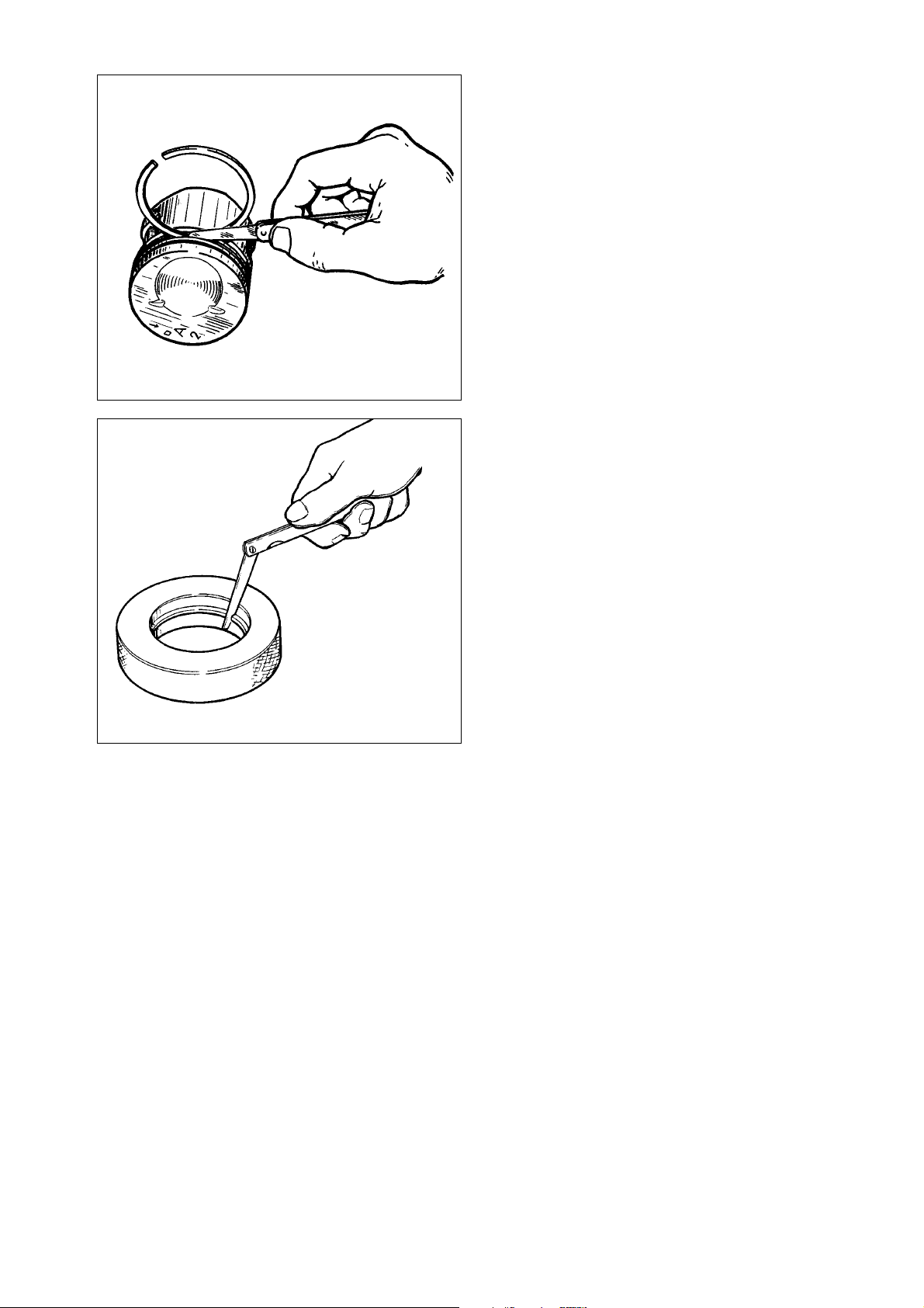
The piston-ring-to-groove wall clearance is checked using
feeler blades as shown in Fig.2-34, fitting the ring into the respective groove. For new components the design clearance (rounded
off to the nearest 0.01 mm) is 0.04-0.07 mm for the first compression ring; 0.03-0.06 mm for the second compression ring and
0.02-0.05 mm for the oil control ring. When worn, the tolerance
must not exceed the specified maximum of 0.15 mm.
The piston ring gap should be checked with a feeler gauge
via inserting the rings into the gauge (Fig.2-35), with the bore
equal to the piston ring nominal diameter ±0.003 mm. Use gauge
67.8125.9502 for the normal 82 mm rings.
The gap for all new piston rings should be within 0.25 to 0.45
mm. The maximum permitted gap for worn rings is 1 mm.
Crankshaft and flywheel
Design description
Basic dimensions of the crankshaft are shown in Fig.2-36.
Crankshaft is cast-iron, of five bearings. The crankshaft
journals can be reground during the engine overhaul when the
diameter is reduced by 0.25 mm, 0.5 mm, 0.75 mm and 1mm.
The crankshaft endfloat is restricted by two thrust washers.
The thrust washers are fitted on both sides of the rear main bearing: a sintered one (yellow) at the rear end and a steel-aluminium
one at the front end. The thrust washers are of two sizes - standard and 0.127 mm thicker.
Crankshaft bearing shells are thin-walled, aluminium with
steel backing. The upper bearing shells of No 1, 2, 4 Ë 5 bearings
have inner oil grooves, whilst the lower bearing shells are plain
shells. The upper and lower bearing shells of the centre bearing
(No 3) are plain, without an oil groove. The big-end bearing shells
(both upper and lower ones) are also plain.
The oversize bearing shells are thicker for the crankshaft
journals reduced by 0.25 mm, 0.5 mm, 0.75 mm and 1 mm.
Flywheel is cast iron with the pressed-in steel starter ring.
The flywheel centering is ensured by a front input shaft bearing
which is pressed into the crankshaft.
A taper recess on the rear face of the flywheel near the ring
gear is provided as a positioning mark. Adjust it against cylinder
No 4 crankpin.
Inspection and overhaul
Crankshaft. Inspect the crankshaft. Make sure there are no
cracks. Examine the faces which mate the oil seal working edges
for evident cracking, scoring or scuffing.
Mount the crankshaft on two V-blocks as shown in Fig.2-37
and check the run-out with a dial gauge:
• main bearing journals - maximum 0.03 mm;
• mounting surfaces for the input shaft sprocket and bearing
- maximum 0.04 mm;
• surface mating the oil seal - maximum 0.05 mm.
Measure the diameters of the main bearing journals and
24
Fig.2-34. Checking the piston ring-to-groove gap
Fig. 2-35. Checking the piston ring gap
Page 25
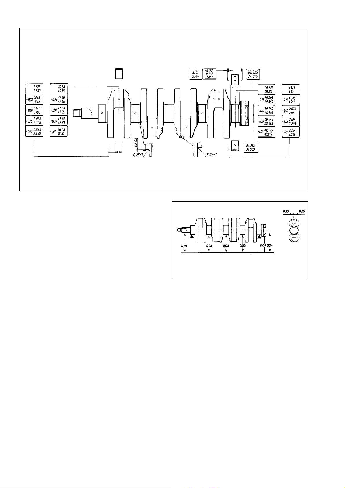
crankpins. Regrind when the wear is in excess of 0.03 mm, ovality is over 0.03 mm, or when scoring and scuffing is obvious.
Regrind the journals and crankpins through reducing the
diameter to the nearest undersize (Fig.2-36).
When regrinding, observe the sizes for the crankshaft fillet as
shown in Fig.2-36 for the standard-size crankshaft.
The ovality and taper for the main bearing journals and big-
end bearing journals after regrinding must not exceed 0.005 mm.
On a reground crankshaft, the vertical offset of the crankpins
axes must be 0.35 mm (Fig.2-37). To check this, place the crankshaft on V-blocks and position the crankshaft so that No1
crankpin axis is in the horizontal plane passing through the main
bearing journal axes. Using a dial gauge, check the vertical offset of crankpins No 2, No 3 and No 4 against crankpin No 1.
After regrinding the journals and crankpins, polish them using
the diamond paste or special grinding pastes.
After regrinding and followed finishing, unplug the oilways,
then machine the plug seats with the mill-cutter Ä.94016/10 and
spindle Ä.94016. Thoroughly wash the crankshaft and oilways to
flush abrasive residuals and blow dry with compressed air.
Use tool Ä.86010 to press in new plugs and punch each plug
in three points with a centre-punch.
On crankshaft web No 1 mark the reduced amount (undersize) of the main bearing journals and big-end journals (eg. M
0.25; B 0.50).
Bearing shells. Remember that no adjustment on the bearing shells is allowed. Renew the shells when there are scratches,
scoring or flaking.
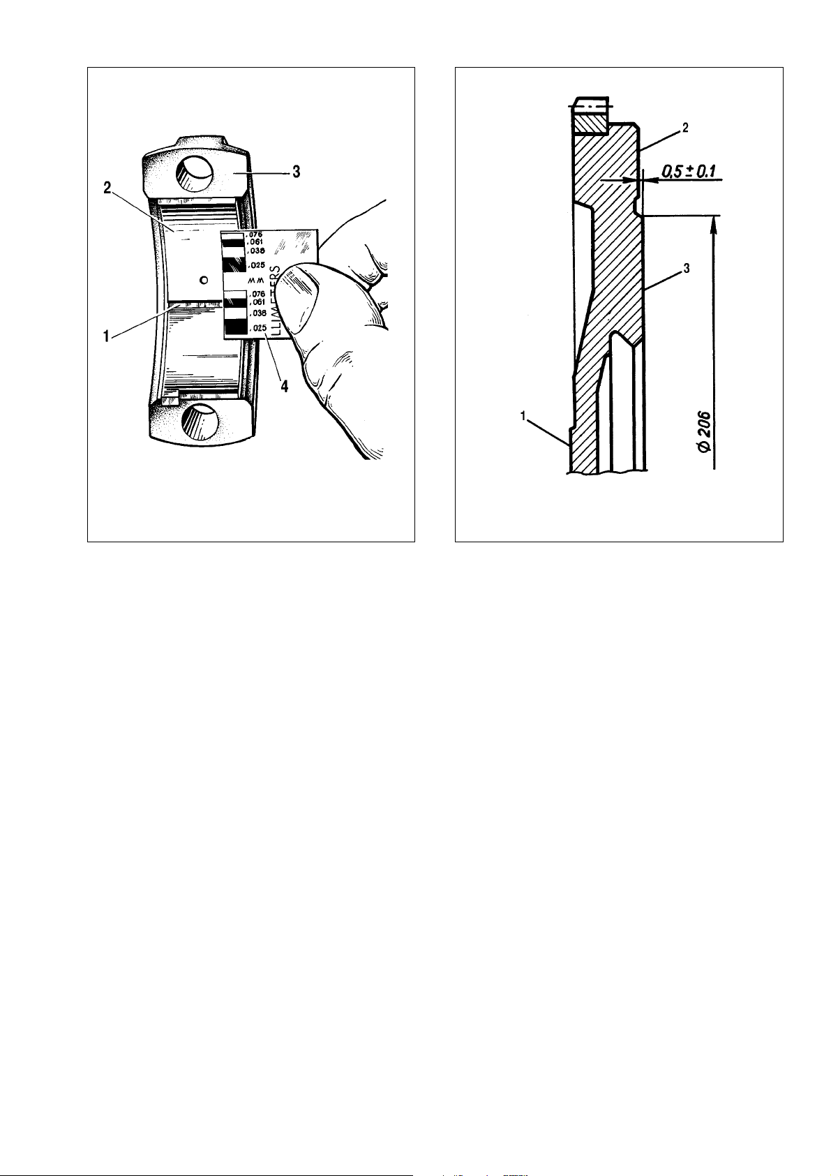
The main and big-end bearing running clearance is checked
by measuring the components. It is convenient to check the
clearance with the help of «Plastigage» (which consists of a fine
thread of perfectly-round plastic, which is compressed between
the bearing cap shell and the crankshaft journal) under the following procedure:
- ensure the journals and bearing shells are clean and dry,
cut several pieces of the appropriate-size Plastigage (they should
be slightly shorter than the width of the bearings) and place one
piece on each crankshaft journal axis;
- with the bearing shells in position in the cages, fit the caps to
their original locations (depending on the journal checked). Take care
not to disturb the Plastigage. Then tighten the securing nuts and bolts
to the specified torque. Tighten the connecting rod bolts to 51 ç•Ï
(5.2 kgf•m), while the main bearing cap bolts to 80.4 ç•Ï (8.2 kgf•m);
- remove the bearing cap and check the running clearance by
comparing the width of the crushed Plastigage on each journal
with the scale printed on the card gauge to obtain the bearing
running clearance (Fig.2-38).
25
Fig.2-36. Basic crankshaft dimensions
Fig.2-37. Permissible runouts for basic crankshaft surfaces
Page 26
The nominal design clearance is 0.02-0.07 mm for the
crankpins and 0.026-0.073 mm for the main bearing journal.
When the running clearance is below the maximum value (0.1
mm for the big-end bearing journals and 0.15 mm for the main
bearing journals), the bearing shells can be re-used.
When the running clearance exceeds the specified maximum, replace the respective bearing shells with new ones.
Where the crankshaft journals are worn and are reground to
their undersize, change the bearing shells to those oversize.
Thrust washers. Similar to the bearing shells, no adjustments are possible on the thrust washers. Always renew the
thrust washers when there is scoring, scuffing or flaking.
The thrust washers must be renewed when the crankshaft
endfloat exceeds the specified limit of 0.35 mm. Select new thrust
washers of the standard size or 0.127 mm thicker to have the
endfloat within 0.06 - 0.26 mm.
The crankshaft endfloat is checked with the help of a dial
gauge as outlined in Section «Engine reassembly» (Fig.2-14).
The crankshaft endfloat can be also checked on the engine in
the vehicle. The axial shift of the crankshaft occurs at depressing
and releasing the clutch pedal, the endfloat value is determined
by the front crankshaft end displacement.
Flywheel. Inspect the teeth of the flywheel starter ring,
should they are found deteriorated, renew the flywheel. If there
are temper colours on flywheel face 3 (Fig.2-39), check the
starter ring interference on the flywheel. The starter ring should
not rotate when applying 590 ç•Ï (60 kgf•m).
Check to see there are no scratches or scores on flywheel
face 1 mating the crankshaft flange or on surface 3 mating the
clutch disc.
Remove by lathing all scratches or scores on face 3, provided the overall thickness is reduced maximum by 1 mm. Do not
forget to lathe surface 2 maintaining the size (0.5±0.1) mm.
Ensure surfaces 2 and 3 are parallel to surface 1. The out-of-parallelism tolerance is 0.1 mm.
Mount the flywheel on the tool, centralize is over the mounting bore against surface 1 and check the run-out of surfaces 2
and 3. The run-out values at the outboard points must not exceed
0.1 mm.
Cylinder head and valve gear
General description
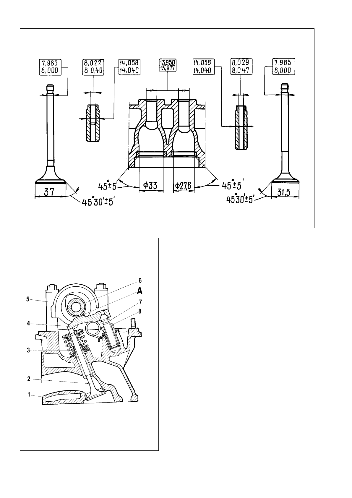
Refer to Fig. 2-40 for basic sizes of the valves, guides and
valve seats.
Cylinder head is an aluminium casting with the pressed-in iron
valve seats and valve guides.
The top of the valve guides is sealed with metal-rubber oil caps
3 (Fig.2-41).
26
Fig.2-38. Measuring the big-end bearing running clearance:
1 - crushed Plastigage; 2 - bearing shell; 3 - big end cap; 4 - scale for clear-
ance measurement
Fig.2-39. Flywheel:
1 - surface mating the crankshaft flange; 2 - surface for clutch securing; 3 clutching surface
Page 27
The outer diameter of the replacement guides is 0.2 mm bigger. Bearing housing 5 with camshaft 6 is fitted to the cylinder
head.
Valve train. Valves 2 are operated by the cams through
levers 4. One end of the lever pushes the valve stem, while the
other end rests on the spherical head of adjuster bolt 7 which
adjusts the clearance A in the valve gear.
Valve clearance adjustment
The clearances are adjusted on the cold engine by means of
the chain adequately tensioned. The adjustment should result is
0.15±0.02 mm clearance for the intake valves and 0.2±0.02 mm
clearance for the exhaust valves.
While making adjustments, do not to twist the valve lever,
since it may result in a bigger final clearance.
The clearance is adjusted as follows:
- turn the crankshaft clockwise to align the indentation in the
camshaft sprocket with the mark on the bearing housing, which
corresponds to the end of the compression stroke of the cylinder
No4. Now in this position adjust the clearance at the cylinder No4
exhaust valve (No8 cam) and cylinder No3 intake valve (No6 cam);
- slacken the valve lever adjuster bolt nut;
- between the valve lever and cam place a flat feeler blade
(A.95111) of 0.15 mm for the intake valve (0.2 mm for the exhaust
valve) and using a spanner tighten or slacken the bolt with further
27
Fig.2-40. Basic dimensions of the valves, valve guides and valve seats
Fig.2-41. Cylinder head cross-sectional view showing the exhaust valve:
1 - cylinder head; 2 - valve; 3 - oil cap; 4 - lever; 5 - bearing housing; 6 camshaft; 7 - adjuster bolt; 8 - lock nut; Ä - cam-to-lever clearance
Page 28
lock nut tightening, until the blade is a firm sliding fit when the lock
nut is tightened (Fig.2-42);
- after the clearance is adjusted at the cylinder No4 exhaust
valve and cylinder No3 intake valve, turn the crankshaft progressively to the 180° and adjust the clearances, observing the
sequence as shown in Table 2-2.
Table 2-2
Valve clearance adjustment
Crankshaft angle, Cylinder No Valve (cam) No
degrees (end of compression stroke)
0 4 8 & 6
180 2 4 & 7
360 1 1 & 3
540 3 5 & 2
Cylinder head - removal and refitting
The cylinder head is removed from the engine in the vehicle,
when no complete stripping of the engine is required, or when
carbon deposits should only be removed from the combustion
chamber and valves. To remove the cylinder head, carry out the
following operations.
Apply the handbrake, remove the spare wheel and disconnect the battery negative lead.
Remove the air cleaner and protect the carburettor with the
provisional plug. Drain the coolant from the radiator and cylinder
block.
28
Fig.2-42. Checking the clearance between the rocker levers and cam
lobes:
1 - feeler blade Ä.95111; 2 - adjuster bolt; 3 - lock nut
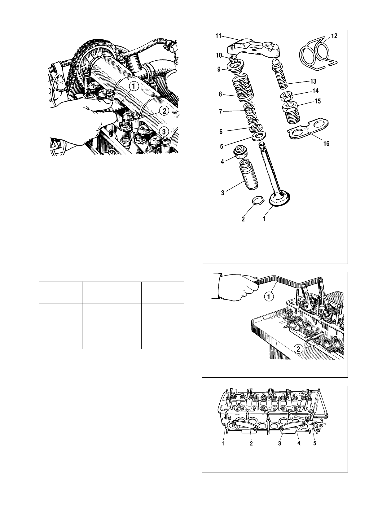
Fig.2-43. Valve components:
1 - valve; 2 - circlip; 3 - valve guide; 4 - oil cap; 5 - lower spring seat, outer
spring; 6 - locking washer, inner spring; 7 - inner spring; 8 - outer spring; 9 upper spring seat; 10 - collets; 11 - valve rocker lever; 12 - valve lever spring;
13 - adjuster bolt; 14 - lock nut, adjuster bolt; 15 - bush, adjuster bolt; 16 - locking plate, valve lever spring
Fig.2-44. Removing the valve spring:
1 - tool Ä.60311/R; 2 - mounting base
Fig. 2-45. Checking the leak-proofness of the cylinder head on tool
A.60334:
1, 2, 4 - plugs; 3 - tool plate; 5 - flange with water supply connector
Page 29

Disconnect the leads from the spark plugs and coolant temperature sender, from carburettor idle switch and fuel cutoff solenoid.
Disconnect the choke cable; disconnect the throttle linkage
from the intermediate lever on the valve cover.
Loosen the clips and disconnect the carburettor supply /
return fuel hoses. Secure the hoses in a manner to exclude possible fuel leaks. Detach the vacuum hose from the carburettor.
Disconnect the hoses from the intake pipe, from the outlet
pipe of the cooling water jacket and from coolant delivery pipe to
the heater. Remove the EGR valve.
Disconnect the starter motor shield from the exhaust manifold, downpipe and detach the bracket securing the coolant pipe
(heater return line).
Remove the valve cover complete with the gasket and fuel
piping securing bracket.
Turn the crankshaft to align the camshaft sprocket TDC mark
against the bearing housing mark (Fig.2-22).
Unbolt the camshaft sprocket. Slacken the chain tensioner
cap nut, release the tensioner rod and fix it in position with the
cap nut. Remove the camshaft sprocket.
Undo the bolts securing the cylinder head to the cylinder
block and remove the cylinder head complete with the gasket.
Refitting of the cylinder head is the reverse order of removal,
refer to the procedure described in section «Engine reassembly».
Never re-use the gasket between the cylinder head and cylinder
block, always replace it with a new one.
While refitting the cylinder head, adjust the timing chain tension and valve clearances. Having refitted the cylinder head,
adjust the carburettor linkage and ignition timing.
Cylinder head - dismantling and reassembly
Dismantling. When only a single part is required to be
replaced, there is no need to completely dismantle the cylinder
head; instead, remove only what is necessary.
Position the cylinder head on the stand, disconnect the hose
from the hot air intake, undo the nuts and remove the carburettor
complete with the gasket; next withdraw the inlet and exhaust
manifolds (the hot air intake is withdrawn at the same time).
Remove the water jacket return pipe and coolant-to-heater
return pipe. Unscrew the spark plugs and coolant temperature
sender.
Undo the securing nuts and remove the bearing housing
complete with the camshaft. Undo the nuts holding the thrust
flange to the bearing housing. Remove the flange and lift out the
camshaft from the bearing housing.
Release springs 12 and remove valve rocker levers 11
(Fig.2-43). Remove the rocker lever springs.
Slacken lock nuts 14, undo adjuster bolts 13 and bushes 15.
Position tool Ä.60311/R, as shown in Fig.2-44, compress the
valve springs and release the collets. A stationary tool
02.7823.9505 can be used instead of tool Ä.60311/R.
Remove the valve springs together with lower and upper
seats. Turn the cylinder head over and remove the valves from
the underneath. Take off the outer caps from the valve guides.
Reassembly. Reassemble the cylinder head in the reverse
order. Before assembly begins, always oil the outer caps and
valves with engine oil.
Before refitting the camshaft bearing housing, check the cen-
tering pins are in the position (Fin.2-21). Tighten the bearing
housing securing nuts in the sequence as shown in Fig.2-23.
Ensure the centering pins are positioned in the bearing housing
recesses without sheering.
The valve clearances are adjusted only after the cylinder
head has been refitted to the engine.
Inspection and overhaul
Cylinder head. Thoroughly wash the cylinder head and
clean the oilways. Scrape away all carbon from the combustion
chambers and from the exhaust valve ports with a wire brush.
Examine the cylinder head. Look to see there is no cracking
in the cylinder head. Check the cylinder head for leakage when
suspicious as to possible oil contamination with coolant.
To do this, plug the cooling water jacket holes (using plugs
from tool A.60334, Fig.2-45), then pump water into the cylinder
head water jacket at 0.5 åP‡ (5 kgf/Òm2). No water leak should
be evident within 2 minutes.
The cylinder head tightness can be checked with compressed
air. Plug the water jacket holes (using the same plugs from tool
Ä.60334), immerse the cylinder head into the bath with water of
60-80°C for 5 minutes. Next pump the compressed air into the
cylinder head at 0.15-0.2 åPa (1.5-2 kgf/Òm2). No air bubbles
must be seen from the cylinder head within 1-1.5 minutes.
Valve seats. The valve seat chamfer shape is shown in
Fig.2-46 and Fig.2-47. Check the working chamfers of the valve
seats (valve contact area) for pitting, corrosion or deterioration.
Minor irregularities of the seats must be recut. Remove as little
metal as possible. Both manual and machine grinding is permitted. Valve regrinding is carried out as follows.
Position the cylinder head on a mounting base. Insert cen-
tering tool A.94059 in the valve guide and clean the seat chamfers from carbon using tools Ä.94031 and Ä.94092 for the
exhaust valves and Ä.94003 and Ä.94101 for the inlet valves.
Use spindle Ä.94058 and centering tool Ä.94059. The centering
tools differ in diameters, use tool Ä.94059/1 for the inlet valve
guides and Ä.94059/2 for the exhaust valve guides.
29
Page 30
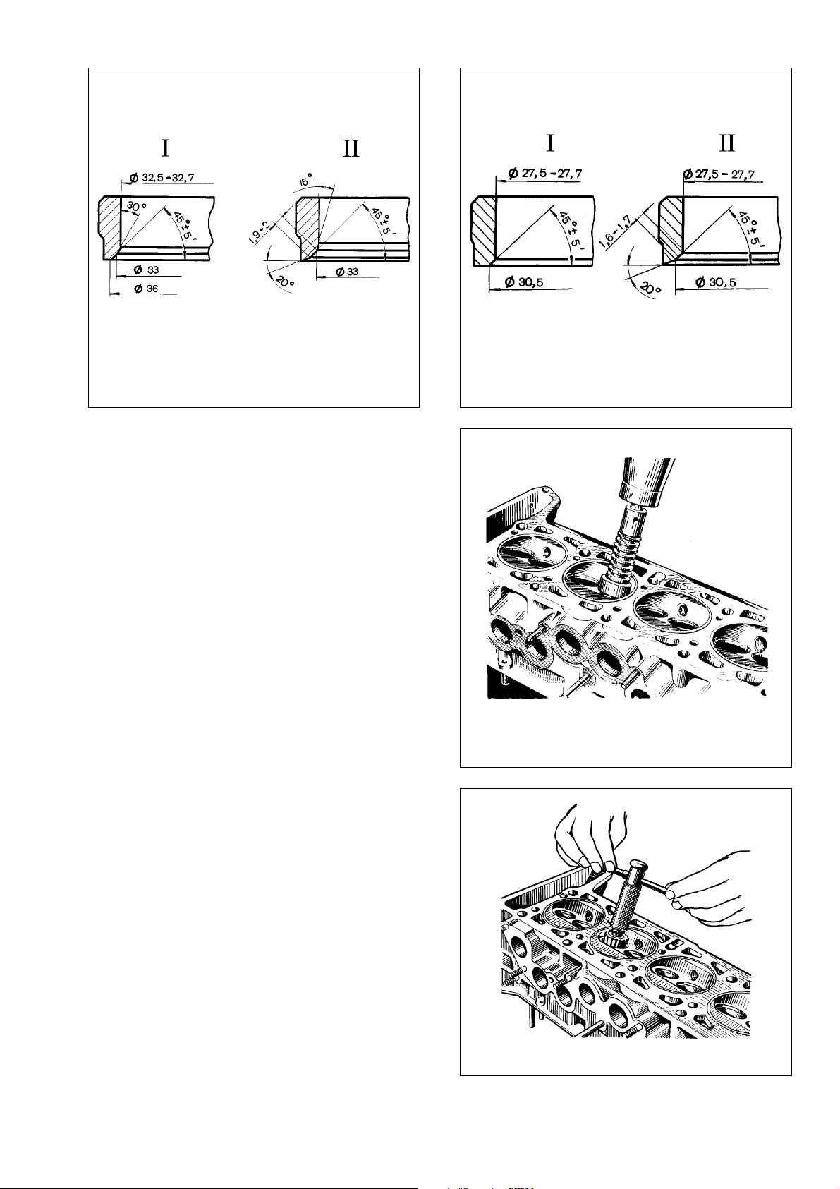
Put spring A.94069/5 on tool Ä.94059, fit tapered wheel
A.94078 on spindle Ä.94069 for the exhaust valve seats or wheel
Ä.94100 for the inlet valve seats, secure the spindle in a grinder
and recut the valve seat (Fig.2-48).
The grinding wheel must be off at the moment the grinding
wheel contacts the valve seat, otherwise vibration ensued will distort the chamfer. Frequent diamond dressing of the wheel is recommended.
The working chamfer width for the exhaust valve seats should
be as shown in Fig.2-46 using tools A.94031 (20°) and A.94092
to remove the wear hardening on the minor diameter. The tools
should be used with spindle Ä.94058 and are centered with tool
Ä.94059.
The working chamfer width for the inlet valve seats should be
as shown in Fig.2-47, first machine the inner chamfer with tool
Ä.94003 (Fig.2-49) to get the diameter of 33 mm, then machine
the 20° chamfer with tool Ä.94101 to achieve the working chamfer width of 1.9-2 mm.
Valves. Scrape away carbon from the valves.
Check the valve stem for deformation; check the valve disc
for cracking. Always renew the damaged valve.
Examine the valve working chamfer. Reface the valve in case
of minor damages, maintaining the chamfer angle at 45°30'
±5'. Note, that the distance between the bottom valve seat face
and base diameter (36 and 30.5) must be as shown in Fig.2-50.
Valve guides. Check the valve guide - to - stem clearance by
measuring the valve stem diameter and valve guide bore.
The clearance for new guides is 0.022 - 0.055 mm for the inlet
valves and 0.029 - 0.062 mm for the exhaust valves; the maximum permissible clearance (in case of wear) is 0.3 mm provided
no excessive noise is produced in the valve train.
30
Fig. 2-47. Exhaust valve seat profile:
I - new seat; II - reconditioned seat
Fig. 2-48. Regrinding the valve seat working chamfer
Fig. 2-49. Reducing the valve seat working chamfer using the cutting tool
with spindle Ä.94058
Fig. 2-46. Intake valve seat profile:
I - new seat; II - reconditioned seat
Page 31

When a new valve fails to take up clearance between the
valve guide and the valve rim, renew the valve guides using tool
Ä.60153/R (Fig.2-51).
Push in the valve guide complete with the circlip to the cylinder head to their stop.
After the valve is pressed into position, ream the valve guide
bores using tool Ä.90310/1 (for the inlet valve guides) and tool
Ä.90310/2 (for the exhaust valve guides).
Valve stem oil caps must always be renewed during the
engine overhaul.
Any damaged oil caps are renewed on the cylinder head
removed. Use special tool 41.7853.4016 to push the oil seals on
the guide.
Springs. Check the springs are not cracked and are adequately tense; load test the springs to reveal any deformation
(Fig.2-52).
31
Fig.2-50. Limit sizes for valve chamfer regrinding:
I - inlet valve; II - outlet valve
Fig.2-51. Pressing out the valve guides:
1- tool Ä.60153/R
Fig.2-52. Basic lengths to check the valve outer (a) and inner (b) springs
Fig.2-53. Valve spring checking diagram:
Ä - dimension in free state; Ç - dimension under load
Page 32

For lever springs (Fig.2-53) the size Ä (spring unloaded)
must be 35 mm, whereas the size Ç (spring loaded 51-73.5 N/
5.2-7.5 kgf) must be 43 mm.
Cylinder head bolts. Multiple use of the cylinder head bolts
results in the bolt elongation. Therefore, check the length of the
bolt (L) to be 120 mm (less the bolt head length), otherwise
renew the bolt.
When replacing the bolts take care not to fit similar bolts from
other VAZ engines of the same type (2101, 21011, 2103, 2107,
2121), but made of different steel.
The 21213 engine bolts have the threaded area of 70 ÏÏ (30
mm for other engines); in addition, the 21213 engine bolts do not
have a distinctive mark (a 7.5 mm diameter recess for wrench).
Valve rocker levers. Check the condition of the lever oper-
ating surfaces which mate the valve stem, cam lobe and adjuster
bolt spherical end.
Always renew the rocker arm when its surfaces are chipped,
scored or scuffed.
Renew the lever adjuster bolt bush or the bolt itself in case of
any deformation or damages found.
Camshaft and timing gear
Design description
Camshaft is cast iron, of five bearings, operates in the alu-
minium bearing housing fitted to the cylinder head.
Basic dimensions of the camshaft and bearing housing are
shown in Fig.2-54. The flanks of the cams are chilled for better
wear resistance.
In order to eliminate the camshaft endfloat, the camshaft is
supported by the thrust flange held in the front journal groove.
Camshaft is operated through crankshaft sprocket 5 (Fig. 2-
55) and double-row roller chain 2. The chain also operates
sprocket 4 of the oil pump shaft. The chain drive has semi-automatic tensioner 8 with shoe 7 and chain damper 3 with rubber
covers.
In the cylinder bottom there is stop pin 6 to prevent the chain
dropping into the crankcase when camshaft sprocket 1 is
removed.
Chain tension adjustment
Loosen nut 1 (Fig.2-56) of the tensioner. This releases rod 3
and the chain is tightened by means of shoe 7 (Fig.2-55) which
is loaded by spring 7 (Fig.2-56).
Turn the crankshaft 1-1.5 turns progressively. By doing that,
the tensioner spring, operating the shoe, automatically adjusts the
chain tension.
Tighten tensioner nut 1, this results in rod 3 clamped by collets 8; during engine operation plunger 6 is effected only by
spring 4. The spring releases the plunger from rod 3 head, so that
the clearance between them is filled with oil that acts as a
damper when the chain strikes.
Chain renewal
Apply the handbrake, open the bonnet, remove the spare
wheel with the supporting tube and withdraw the battery.
Remove the air cleaner and close the carburettor inlet filler
with a provisional cap. Disconnect the throttle and choke cables
from the carburettor.
32
Fig2-54. Basic dimensions of the camshaft and the bearing housing
Page 33

Drain the cooling water from the radiator and cylinder block,
remove the radiator complete with the hoses and thermostat.
Undo the retaining nuts and remove the fan.
Remove the valve cover and turn the crankshaft to align the
TDC mark in the camshaft sprocket against the timing mark in the
bearing housing (Fig.2-21), while the alternator belt pulley marks
are aligned against a long mark in the timing cover (Fig.7-18).
Undo the camshaft sprocket retaining bolt. Slacken the chain
tensioner cap nut, release the tensioner rod and fix it in position
using the cap nut. Remove the camshaft sprocket.
Slacken the alternator and remove the alternator drivebelt.
Apply the 4th gear of the gearbox, undo the nut and withdraw the
alternator drivebelt pulley from the crankshaft.
Remove the timing cover complete with the gasket. Undo the
nuts holding the cover to the cylinder block; then undo the bolts
retaining the oil sump to the cover.
Undo stop pin 6 (Fig.2-55) and withdraw the camshaft timing
chain.
The refitting procedure is a reversal of removal, observing
the recommendations outlined in section «Engine assembly».
Before refitting, smear the chain with engine oil. Always use new
gaskets for the timing cover and valve cover.
The chain refitted, adjust the chain tension and alternator dri-
vebelt tension, adjust the carburettor linkage and ignition timing.
Inspection
Camshaft. The camshaft journals must have no scores,
scuffs, scratches or aluminium galling from the bearing housing.
The maximum wear of the cam lobe surfaces is 0.5 mm, there
should be no evident scoring or cut-type wear of the cams.
Mount the crankshaft on two V-blocks, located on the test
plate and using a dial gauge, check the centre camshaft journal
endfloat to be 0.04 mm maximum. If the endfloat exceeds the
value specified, straighten the camshaft on the straightening
press.
33
Fig.2-55. Camshaft and ancillaries drive:
1 - camshaft sprocket; 2 - chain; 3 - chain damper; 4 - oil pump shaft
sprocket; 6 - stop pin; 7 - tensioner shoe; 8 - chain tensioner
Fig.2-56. Sectional view of the chain tensioner:
1 - cap nut; 2 - tensioner housing; 3 - core; 4 - spring; 5 - washer; 6 - plunger;
7 - spring; 8 - collet; 9 - spring ring;
Ä - plunger surface; Ç - centre-punch points on housing face
Fig.2-57. Basic data for checking the tensioner spring
Page 34

Camshaft bearing housing. Wash and clean the bearing
housing, flush clean the oilways.
Check the diameters of the holes in the bearings. When the
clearance between the camshaft journals and bearing surfaces
exceeds 0.2 mm (wear limit), renew the bearing housing.
The inner bearing surfaces should be smooth, with no scores;
renew the bearing housing in case of damages. Check the housing for cracks; if this is the case, renew the bearing housing.
Chain tensioner. When the tensioner plunger is seized in the
housing, dismantle the chain tensioner. For that undo cap nut 1
(Fig.2-56), push plunger 6 full way, then tighten the cap nut. File
the housing edges at the points B of centre-punching, withdraw
plunger 6 with spring 4. Undo the cap nut and withdraw rod 3
complete with spring 7 and washer 5. Prise free spring ring 9 and
take out clamping collet 8 from cap nut 1.
Check collet 8, core 3 and plunger 6 for scores, check the
mating surfaces of the tensioner shoe and plunger for deep
scores. Always renew any damaged components.
The spring tension should be within the range specified in
Fig.2-57; otherwise renew the spring.
Check to see the shoe and chain damper do not have excess
wear; renew them when applicable.
Refitting is a reversal of removal. Once the plunger is refitted,
center-punch housing 2 at three points B. Make certain the projections caused by centre-punching do not contact the surface A
during the plunger stroke.
Note: The spring ring is used in some vehicles instead of
centre-punching.
Camshaft timing chain. Wash the chain in kerosine, examine the chain links. Check to see there are no scores, cracks or
other damages.
In the course of the engine operation the chain lengthens.
The chain deems operable as long as the tensioner ensures its
proper tension, i.e. the chain length is maximum 4 mm longer.
Check the chain length with the help of tool 67.7824. 9521
(Fig.2-58), having 2 special-type wheels 1 on which the chain is
located. Using counterweight 3 the chain is extended through
applying force of 294 N (30 kgf) or 147 N (15 kgf). Use adjuster
nut 2 to ensure the counterweight axis is parallel to the tool base.
Apply force 294 N (30 kgf) with the counterweight in the
extreme right position, then decrease the force by 147 N (15 kgf)
moving the counterweight fully to the left. Repeat both operations
and determine the chain difference on the length L (Fig.2-59)
between the axis of the wheels. Using vernier calipers, measure
the distance between the wheels, then add the diameter d value
to get the distance L between the wheels axes.
For a new chain the distance L between the wheels axes is
495.4-495.8 mm. Renew the chain, when its length is 499.5 mm.
Before refitting, smear the chain with engine oil.
ëooling system
Refer to the cooling system layout as shown in Fig.2-60.
Checking coolant level and density
Check to make certain the coolant level in the expansion tank
is adequate. When the engine is cold (15-20°C), the coolant level
within the expansion tank must be 3-4 cm above the «MIN» mark.
WARNING. Always check the coolant level on the cold
engine, since its volume increases with rise in temperature;
the coolant level can be significantly higher with the hot
engine.
When necessary, use an areometer to check the coolant
density to be 1.078-1.085 g/cu.cm for TOSOL A-40 which is used
in VAZ vehicles.
34
Fig. 2-58. Tool 67.7824.9521 for checking the chain wear (extension):
1 - roller; 2 - adjuster nut; 3 - counterweight
Fig.2-59. Checking the chain wear (extension):
1- pulleys
Page 35

When the level in the expansion tank is below the value specified, while its density is in excess of that required, top up distilled
water.
When the density is as recommended, top up the correct
coolant of the same grade as that in the cooling system.
When the coolant density is below the value specified, while
the vehicle will be used in cold conditions, change the coolant.
Coolant change
Change coolant at the intervals recommended or after the
engine overhaul. Fill the cooling system, as described below:
- undo the radiator and expansion tank caps, open the heater
tap;
- disconnect the heater hose (top) from the union on the vehi-
cle body;
- pour coolant (10.7 litre) to the radiator (up to the upper filler
edge) until it starts flowing from the hose and heater union;
- reconnect the heater hose with the union and refit the radiator cap. Top up the remaining coolant into the expansion tank,
refit and tighten the filler cap;
- to remove air pockets, start the engine, run it idle until the
coolant temperature reaches the temperature of the thermostat
opening (80±2)°C. Check to see the radiator inlet and return
pipes are hot.
Leave the engine to cool and check the coolant level. When
the level is below that required, while there are no evident system leaks, top up coolant as necessary.
35
Fig.2-60. Engine cooling system:
1 - radiator return hose; 2 - thermostat; 3 - thermostat hose; 4 - return hose to pump; 5 - return pipe, heater radiator; 6 - delivery pipe, heater radiator; 7 - return hose
from intake manifold preheater to part throttle channel heater; 8 - part throttle channel heater; 9 - expansion tank; 10 - coolant temperature sensor; 11 - hose between
radiator and expansion tank; 12 - radiator feed hose; 13 - left-hand fluid cooler; 14 - radiator cap; 15 - radiator matrix; 16 - fan ring; 17 - radiator drain tap; 18 - radiator mounting rubber; 19 - right-hand fluid cooler; 20 - water pump; 21 - feed hose to pump
Page 36

36
Fig.2-61. Checking the water pump belt tension
Fig.2-63. Removing the impeller:
1 - puller; 2 - impeller
Fig.2-62. Sectional view of the coolant pump:
1 - pulley hub; 2 - shaft; 3 - cover; 4 - impeller; 5 - housing; 6 - thrust ring; 7 - oil seal; 8 - bearing stop screw; 9 - pulley; 10 - blower fan; 11 - cover plate; 12 - fan hub
Page 37

Water pump drivebelt tension adjustment
The belt tension is checked by exerting a hand pressure on
the chain between the alternator pulley and pump pulley or
between the pump pulley and crankshaft pulley. With proper tension, slack A in the belt (Fig.2-61) at 98 N (10 kgf) must be 10-15
ÏÏ, while at the same pressure the deflection Ç must be within
12-17 mm.
To adjust the belt tension, slacken the alternator retaining nuts,
move the alternator off the engine (to increase tension) or towards
the engine (to decrease tension), then tighten the nuts. Turn the
crankshaft two revolutions clockwise and check the belt tension.
No excess tension of the belt is allowed to prevent hazardous
loads to the alternator bearings.
Coolant pump
Dismantling. Carry out the coolant pump dismantling as
detailed below:
- disconnect pump housing 5 (Fig.2-62) from cover 3;
- place the cover in vice using protective pads; remove
impeller 2 (Fig.2-63) from the shaft using picker Ä.40026;
- remove hub 2 (Fig.2-64) of the fan pulley from the shaft
using puller Ä.40005/1/5;
- undo lock screw 8 (Fig.2-62) and force out the shaft with the
bearing, applying force to the bearing race;
- withdraw oil seal 7 from housing cover 3.
Inspection. Check the bearing axial clearance. This operation is mandatory if the pump is noisy. The clearance must not
exceed 0.13 mm at load of 49 N (5 kgf). Renew the bearing complete with the shaft when the clearance is bigger.
Always remember to renew the pump oil seal and pump-tocylinder block gasket during overhaul.
Check the pump housing and cover for cracks or deformation,
which are not permitted.
Reassembly. The assembly is carried out as follows:
- using the appropriate tool, fit the oil seal to the housing
cover, look out not to skew;
- press in the bearing and shaft, applying the force to the
bearing race so that the holes for the locking screw are matched;
- tighten the bearing lock screw and punch the seat over the
contour to prevent its self-loosening;
- using tool Ä.60430 (Fig.2-65) press the pulley hub onto the
shaft, maintaining a size of (84.4±0.3) mm. When the hub is of
sintered quality, press in the new hub only.
- using tool A60430, press the impeller onto the shaft, maintaining a size of (48-0,2) mm, as shown in Fig.2-62. This ensures
the required clearance between the impeller blades and pump
housing;
- reassemble the pump housing with the cover, having placed
the gasket in-between.
Thermostat
To test whether the unit is serviceable, check the temperature
of the main valve opening and valve travel.
Using the test bench Åë-106-000, suspend the thermostat
with a piece of string in a container of water or coolant. Position
the bracket arm of the gauge against main valve 9 (Fig.2-66).
37
Fig.2-64. Removing the pulley hub:
1 - pump housing cover; 2 - pulley hub; 3 - tool Ä.40005/1/5
Fig.2-65. Fitting the impeller to the pump shaft using tool Ä.60430:
1 - base; 2 - pump shaft; 3 - pump housing cover; 4 - shell; 5 - set screw
Page 38

Gradually heat the water from the starting 73-75°ë in incre-
ments of approximately 1°ë per minute, at constant agitation to
ensure homogeneous heating within the container.
The value, when the valve travel is 0.1 mm, is deemed as the
initial temperature of the main valve opening.
The main valve opening temperature is stated on the ther-
mostat face side and is (80±2)°ë or (83±2)°ë. The thermostat is
subject to renewal when its main valve opening temperature differs from the value stated on the thermostat face or when the
main valve stroke is below 6.0 mm.
The easiest way to check the thermostat is serviceable, is to
touch it directly in the vehicle. The thermostat is good when after
the engine cold start, the lower radiator pipe gets warmer as soon
as the coolant temperature reaches 80-85°C (the coolant temperature gauge needle is 3-4 mm from the red area of the scale).
Radiator
Removal. Withdraw the radiator from the vehicle in the following order:
- remove the spare wheel and its supporting tube;
- drain the fluid from the radiator and cylinder block through
the respective caps in the left-hand fluid cooler and cylinder block;
open the heater drain tap and remove the radiator filler cap;
- disconnect the hoses from the radiator;
- separate the fan cowl halves and withdraw the fan cowl;
- undo two bolts holding the radiator to the body, release the
upper catch of the radiator cowling upwards, move the radiator
top towards the engine and withdraw the radiator from the engine
compartment;
- take out the radiator cowling.
Radiator leak test. The radiator tightness is checked in a
container full of water.
Plug the radiator pipes, apply air at pressure of 0.2 åPa (2
kgf/Òm2) and immerse the radiator into the water for at least 30
seconds. The radiator should show no air bubbles.
Repair or renew the radiator when it is found leaky or damaged.
Radiator repair. In the event the aluminium tubes are damaged, dismantle the radiator, drill the defective tubes from both
ends to a depth of 25-30 mm, using a drill of 8.5 mm diameter.
Fit the undersize tubes (flared at one end) of 7.3 mm diameter and 0.5 mm wall thickness into the defective tubes. Then on a
special stand push the tubes all the length down using a steel
core of 7.5±0.05 mm.
On the respective bench expand each tube from both ends
simultaneously.
Assemble the radiator and check it for tightness.
Lubrication system
Refer to Fig.2-67.
Engine oil change
Change oil only when the engine is hot. Allow at least 10 minutes, after the drain plug is removed, for all the oil to drain.
Oil renewal should be accompanied by the oil filter removal;
use tool Ä.60312 (Fig.2-4) to undo the filter. When refitting, screw
the filter into position on the engine and tighten the filter by hand
only - do not use any tools.
Change oil in the following order:
- stop the engine, drain the oil and without removing the oil filter, pour cleaner oil to the «MIN» mark of the oil dipstick (2.9 litre).
Use oil equivalent to grades Ззаази-оС, ели-1 or еин-2е;
- start the engine and run it for 10 minutes at low rpm;
- completely drain the cleaner oil and discard the old oil filter;
- fit a new oil filter and pour oil of respective season grade.
Oil pump
The basic dimensions of the pump components and its link-
age are shown in Fig.2-68.
38
Fig.2-66. Thermostat:
1 - intake manifold (engine side); 2 - relief valve; 3 - relief valve spring; 4 - shell;
5 - rubber insert; 6 - exhaust manifold; 7 - main valve spring; 8 - main valve seat;
9 - main valve; 10 - retainer; 11 - adjuster nut; 12 - piston; 13 - sleeve;
D - coolant inflow from engine; ê - coolant inflow from radiator;
ç - coolant outflow to pump
Page 39

39
Fig.2-67. Lubrication system:
1 - oil passage to main bearing; 2 - main bearing-to-big-end bearing oil passage; 3 - oil filter relief valve; 4 - paper element; 5 - check valve; 6 - oil pump; 7 - oil pump-tooil filter oil passage; 8 - oil passage from oil filter to main oil gallery; 9 - oil passage to oil pump gear and ignition distributor; 10 - oilway to oil pump shaft and ignition distributor; 11 - oil pump and ignition distributor shaft; 12 - oilway in outer gear to feed oil to chain; 13 - camshaft; 14 - oil recess, camshaft centre bearing journal; 15 - cam
lobe oilway; 16 - oilway, camshaft bearing journal; 17 - cylinder head vertical oil passage to valve timing gear; 18 - oil gallery; 19 - oil pressure warning light sender
Page 40

Removal and refitting. When only the oil pump requires recon-
ditioning, remove it from the vehicle (Refer to section «Engine removal and refitting»), place it on the turning stand, drain the oil
from the sump, turn over the engine and remove the sump. Undo
the oil pump bolts and remove the pump complete with the intake
manifold assembly.
Refitting is the reversal order of removal.
Dismantling and reassembly. Position the oil pump in vice
taking care not to damage the pump housing, then:
- undo the bolts and remove the intake manifold complete
with the oil pressure relief valve;
- remove cover 3 (Fig.2-69) and withdraw the pump shaft
complete with the inner and outer gears from the housing.
To reassemble the pump, position the pump in vice and carry
out the following operations:
- refit the inner gear with the shaft, then the outer gear;
- refit the pump cover, pressure relief valve with the spring and
bolt the intake manifold assembly to the pump body.
Note. On completing the pump assembly, turn the inner gear
by hand to check the gears are running smoothly, without jerks or
seizures.
Inspection. After dismantling, wash all components in kero-
sine or petrol, blow dry with compressed air, then check the pump
housing and cover for cracks, renew when applicable.
Using feeler blades, check the backlash in the gears and the
radial play (Fig.2-70) to be respectfully 0.15 mm (maximum permissible value is 0.25 mm) and 0.11-0.18 mm (maximum permissible value is 0.25 mm). If the tolerances are exceeded, then the
gears or pump housing should be renewed.
Using a feeler gauge and a straight-edge (Fig. 2-71), check
the axial clearance to be 0.066-0.161 mm (maximum permissible
value is 0.20 mm). When the clearance is over 0.20 mm, renew
the gears or pump housing whichever is worn out.
Having taken the measurements, determine the clearance
between the outer gear and its axle to be 0.017-0.057 mm (maximum permissible value is 0.10 mm) and the clearance between the
oil pump shaft and the housing bore to be 0.016-0.055 mm (maximum permissible value is 0.10 mm). Renew any worn parts when
the tolerances exceed the values specified.
Checking the pressure relief valve. Always inspect the
pressure relief valve during the oil pump repair. Draw special
attention to the valve surfaces and bores in the intake manifold
assembly, since possible contamination or sediments on the mating surfaces can result in the valve seizures.
The mating valve/pump cover surfaces should show no dents
or flash to prevent a drop of oil pressure in the lubrication system.
Check the relief valve spring tension against the values as
given in Fig.2-72.
40
Fig.2-68. Basic dimensions of the oil pump components and associated parts
Page 41

Oil pump shaft and drive gears
Check to see there is no denting or scuffing of the shaft bear-
ing journals or eccentric cam surfaces.
No pitting of the oil pump gears or ignition distributor is per-
mitted, if this is the case, renew the gears and shaft.
Oil pump shaft bushes. Check the inner diameter of the
bushes, their proper fitting, make certain the oil port in the front
bush is aligned against the oilway in the cylinder block (bush turning). The inner surface must be smooth and without scuffs.
Measure the diameter of the shaft and bushes to determine
the clearances between the bushes and shaft bearing surfaces.
When the clearance is over 0.15 mm (limit wear value), or in case
of damaged or loose bushes, renew the bushes.
For removal and refitting use tool Ä.60333/1/2 (Fig. 2-73),
observing the following:
- the bushes must be pressed in place with the oil port in the
front bush aligned against the oilway in the cylinder block;
- after pressing in, the bushes are machined to the final inner
diameter (Refer to Fig.2-68 for the sizes). For optimum concentricity of the shaft bushes, use the finishing reamer Ä.90353 for concurrent machining of both bushes.
Oil pump inner gear bush. Check the bush is adequately
pressed in. The inner surface should be smooth, with no scuffs,
otherwise renew the bush.
Use tool Ä.60326/R for bush pressing-in or out (Fig.2-74).
After pressing-in, ream the bush to 16.016-16.037 mm.
41
Fig.2-69. Dismantling the oil pump:
1 - relief valve; 2 - valve spring; 3 - cover; 4 - housing; 5 - shaft
Fig. 2-70. Checking the oil pump radial play
Fig. 2-71. Checking the oil pump endfloat
Fig.2-72. Basic data for checking the relief valve spring
Page 42

Crankcase emission ventilation system
Flushing the system. For flushing disconnect vent hoses 4
and 5 (Fig. 2-75) from the manifolds, remove flame arrester 3
from discharge hose 5, remove cover 6 of oil separator 7 and
wash them in petrol or kerosine.
Flush and blow dry with compressed air the carburettor manifold to draw crankcase emission on the throttle body (to the side
of the air cleaner).
42
Fig.2-73. Removal and refitting of the oil pump / distributor shaft bush:
1 - tool Ä.60333/1/2
Fig.2-74. Pressing out the oil pump / distributor inner gear bush:
1 - tool Ä.60326/R
Fig.2-75. Crankcase ventilation diagram:
1 - filter element, air cleaner; 2 - exhaust manifold; 3 - flame arrester; 4 - hose
to draw crankcase emission on throttle body; 5 - discharge hose; 6 - oil separator cover; 7 - oil separator; 8 - oil separator drain tube
Page 43

Fuel system
Air cleaner and temperature regulator
Removal and refitting. To remove the air cleaner, release
spring retainers 14 (Fig. 2-76) and undo nut 7 securing air cleaner cover 8. Remove the cover and lift out filter element 10.
Undo the nuts holding housing 13 to the carburettor.
Disconnect hose 2, then remove the air cleaner and temperature
regulator 5.
Loosen clamp bolt 6 and remove temperature regulator 5
complete with cold air intake 4.
When refitting the air cleaner, position the arrow on the filter
cover as shown in Fig. 2-77 in order to reduce intake air noise.
Fuel tank
Removal and refitting. Before removing fuel tank 1 (Fig.2-
78), disconnect the battery earth lead.
Undo cap 5 of filler pipe 4 and remove as much petrol as possible.
Remove the rear seat, undo screws holding the right-hand
and left-hand wheel arch liner, remove the liners.
Unbolt and remove the cover in the floor to expose the fuel
tank. Disconnect hoses 9 and wiring from fuel level sender 8, followed by hoses 2 from the fuel vapour separator.
Undo the retaining bolts and withdraw the petrol tank.
The fuel tank refitting is a reversal of removal.
Cleaning and inspection. Remove the fuel level sender.
Clean the tank with petrol to remove any contaminants or sediments. Wash the tank with a jet of hot water and steam out any
petrol residuals.
Thoroughly examine the fuel tank welding seam for leaks. If
leakage is evident, solder the fuel tank.
WARNING. Before soldering, check to see the fuel tank
is thoroughly cleaned and steam-treated and there are no
fuel vapours which can ignite and explode during soldering.
Fuel pump
Refer to Fig.2-79.
Fuel pump inspection. Insufficient fuel flow to the carburettor can be caused by a faulty fuel pump, clogged or damaged fuel
lines or fuel filter.
To find the cause of failure, disconnect the hose from supply
manifold 1 and using fuel priming lever 8, check fuel delivery. If
there is no fuel, disconnect the hose from intake manifold 4 and
check the manifold for vacuum. In case of vacuum, the fuel lines
are damaged, if not - the fuel pump is faulty.
The fuel pump can be tested on a stand. By rotating the drive
shaft at 2000±40 rpm, check the fuel delivery by the pump to be
at least 54 litre/hour at 20±5°ë, while the supply pressure at
«zero» fuel delivery must be 0.02-0.03 åP‡ (0.21-0.30 kg/cm2 ).
When found defective, dismantle the fuel pump and examine all
its components.
Dismantling, cleaning and inspection. To dismantle,
unbolt cover 5, remove the cover and fuel pump filter 2. Next
undo the screws holding the housing to the lower cover, separate
them, withdraw the diaphragm unit and spring. Wash all components in petrol and blow dry with compressed air.
Examine the state of components. The pump springs must
be undamaged. Check the valves are not sticking. The
diaphragms must have no fractures, cracks or hard spots.
43
Fig.2-76. Air cleaner and temperature regulator:
1 - gasket; 2 - corrugated hose; 3 - air temperature control flap handle; 4 - cold
air intake; 5 - temperature regulator; 6 - clamp bolt; 7 - air cleaner cover securing nut; 8 - air cleaner cover; 9 - air cleaner cover gasket; 10 - filter element;
11 - filter cover mounting bracket; 12 - emission discharge pipe; 13 - air filter
housing; 14 - spring retainer; 15 - warm air intake from exhaust manifold
Fig.2-77. Refitting the air cleaner cover
Page 44

44
Fig.2-78. Fuel tank and fuel pipeline associated components
1 - fuel tank; 2 - hoses, fuel vapour separator and fuel tank; 3 - fuel vapour separator; 4 - filler pipe; 5 - cap; 6 - hose, fuel tank and filler pipe; 7 - hose, fuel vapour separator and fuel tank cover; 8 - fuel level sender; 9 - connection hoses; 10 - grommet; 11 - return flow line; 12 - fuel line; 13 - hose clips; 14 - non-return valve; 15 - carburettor; 16 - fuel pump; 17 - fine fuel filter
Fig.2-79. Fuel pump:
1 - delivery pipe; 2 - filter; 3 - housing; 4 - suction pipe; 5 - cover; 6 - suction valve; 7 - operating rod; 8 - hand priming lever; 9 - spring; 10 - eccentric; 11 - rocker; 12 mechanical priming lever; 13 - lower cover; 14 - inner distance gasket; 15 - outer distance gasket; 16 - delivery valve
Page 45

Check and renew any worn components. Always fit new pump
gaskets, remember to lubricate the gaskets with a thin layer of
grease before refitting them to the pump.
Refitting pump to engine. For correct fitting, use two out of
three gaskets as stated below:
«Ä» gasket of 0.27-0.33 mm;
«Ç» gasket of 0.70-0.80 mm
«ë» gasket of 1.10-1.30 mm.
Refit as shown in Fig.2-80 in the following sequence.
Locate the gasket A, then heat screen to the cylinder block,
next place the gasket B on the face mating the pump. Using tool
67.7834.9506 measure the distance «d» (minimum rod protrusion to be set through slow crankshaft rotation). When the size
«d» is within 0.8-1.3 mm, secure the fuel pump to the engine.
When the size «d» is below 0.8 mm, replace the gasket Ç with
the gasket Ä. When the size «d» is over 1.3 mm, replace the gasket Ç with the gasket ë. Recheck the size «d» and secure the
pump to the engine.
Make sure the gasket Ä is always fitted between the cylinder
block and heat screen.
45
Fig.2-80. Checking and adjusting the fuel pump pushrod projection:
Ä - gasket of 0.27-0.33 mm; Ç - gasket of 0.70-0.80 mm;
d - pushrod projection
Page 46

Carburettor
General description
The engine is fitted with the 21073-1107010 carburettor
(Fig.2-81) of emulsion, twin progressive throttle type. The carburettor features a balanced float barrel, a system of drawing
crankcase emission on the throttle body, a part throttle channel
heater and secondary barrel locking.
The carburettor has two main fuel jet systems for the primary
and secondary barrels, a primary barrel idling system with air correction, a secondary barrel air correction system, part throttle
enrichment (economizer), full throttle enrichment (econostat),
diaphragm-type accelerator pump, semi-automatic choke control
unit.
On the overrun an idling overrun control unit is actuated.
Refer to Table 2-2 for carburettor data.
46
Fig.2-81. Carburettor 21073-1107010:
1 - throttle valve lever; 2 - secondary barrel lock lever pin; 3 - primary throttle valve opening adjustment screw; 4 - screw for choke valve cable end fitting; 5 - choke valve
control lever; 6 - choke valve lever; 7 - choke valve return spring; 8 - diaphragm rod, pull-down unit; 9 - fuel shutoff solenoid; 10 - fuel supply manifold; 11 - bracket for
choke outer cable end fitting; 12 - secondary barrel adjuster screw; 13 - secondary throttle valve lever; 14 - secondary throttle lever; 15 - primary throttle return spring
Page 47

Table 2-2
21073-1107010 CARBURETTOR
Parameters Primary barrel Secondary barrel
Barrel diameter, mm 32 32
Venturi diameter,mm 24 24
Main jet system:
• fuel jet marking* 107.5 117.5
• air jet marking 150 135
Emulsion tube, type ZD ZC
Idling and air correction systems, primary barrel:
• fuel jet marking 39
–
• conventional flow,** air jet 140 –
Air correction system, secondary barrel:
• conventional flow, fuel jet
– 70
• conventional flow, air jet
– 140
Full throttle enrichment (econostat):
• conventional flow, fuel jet
– 70
Part throttle enrichment (economizer):
• fuel jet marking 40
–
• spring compression (9.5 mm length), N 14.5±15%
Accelerator pump:
• atomizer marking 45
–
• delivery (10 full strokes), cc 14 –
• cam marking 4 –
Starting clearances***:
• choke valve (clearance Ç), mm 3.0
–
• throttle valve (clearance ë), mm 1.1 –
Diameters,mm:
• crankcase vent drilling 1.2
–
• vacuum advance unit orifice 1.2
• needle valve bore 1.8
• fuel return orifice to petrol tank 0.70
__________________________________________________________________________________
* Jet marking is flow-related. Flow rate is measured with a micrometer, calibrated against the reference jets.
** Conventional flow through the jet is determined against the reference jet under a special procedure; in operation no control is required.
***Starting clearances are as shown in Fig.2-86
47
Page 48

48
Fig.2-82. Main metering system:
1 - main air jets and emulsion tubes; 2 - atomizers, primary and secondary barrels; 3 - balance orifice; 4 - fuel filter; 5 - return pipe with calibrated orifice to petrol tank; 6
- needle valve; 7 - float; 8 - secondary throttle valve; 9 - main fuel jets; 10 - primary throttle valve
Fig.2-83. Idling and air correction systems:
1 - fuel cut-off solenoid; 2 - idling fuel jet; 3 - idling air jet; 4 - fuel jet and tube, secondary air correction system; 5 - air jet, secondary air correction system; 6 - outlet orifice, secondary air correction system; 7 - main fuel jets; 8 - primary air correction passage; 9 - idle mixture adjustment screw
Page 49

Main metering system. Fuel through gauze filter 4 (Fig. 2-
82) and needle valve 6 is fed to the float chamber. From the float
chamber fuel flows through main fuel jets 9 to the emulsion wells
to be mixed with air, escaping from emulsion tubes 1 which are
built as one piece with the main air jets. Through atomizers 2 the
air-fuel mixture flows to the primary and secondary venturi.
Throttle valves 8 and 10 are connected so that the secondary
barrel starts opening when the primary one is 2/3 open.
Idling system runs on fuel from the emulsion well behind
fuel jet 7 (Fig.2-83). Fuel is fed to fuel jet 2 which is fitted with fuel
cut-off solenoid 1. At the jet outlet the fuel is mixed with the air
coming from the port and from a flared part of the venturi (to
ensure the carburettor smooth operation at idling). Emulsion goes
under the throttle plate through the correcting orifice adjusted by
idle mixture adjustment screw 9.
Air correction systems. Following the throttle opening but
prior to activation of the main metering system, the air-fuel mixture enters:
- the primary barrel through idling fuel jet 2 and air correction
system passage 8, located at the level of the closed throttle plate
edge;
- the secondary barrel through outlet orifice 6 being slightly
over the edge of the closed throttle plate. Fuel flows from jet 4
through the tube to be further mixed with air from air jet 5 flowing
through the idling air passage.
Part throttle enrichment (economizer) operates when cer-
tain vacuum level is maintained on throttle body 5 (Fig. 2-84).
Fuel is fed from the float chamber through ball valve 8. Valve 8
remains closed as long as the diaphragm is held retracted in the
intake pipe by means of the vacuum. With wide open throttle, the
vacuum decreases allowing diaphragm 7 spring to open the
valve. Petrol which flows through part throttle enrichment jet 9 is
added to fuel passing through main fuel jet 4, providing a richer
mixture.
Full throttle enrichment (econostat) operates at full engine
load, at high, close-to-maximum speeds and wide open throttles.
Petrol from the float barrel through jet 3 (Fig.2-84) is delivered to
the fuel pipe and further through injection tube 13 into the secondary barrel resulting in a richer mixture.
Accelerator pump is of diaphragm type, mechanically oper-
ated by cam 6 (Fig.2-85) on the primary throttle spindle. With the
throttle valve closed, the spring retracts diaphragm 3 thus filling
the pump with petrol through ball valve 8. As the throttle opens,
the cam operates lever 5, whilst diaphragm 3 forces fuel through
ball valve 2 and atomizer 1 into the barrels enriching the air-fuel
mixture.
The pump capacity is invariable and is determined by the
cam profile only.
Choke control unit. Choke lever 4 (Fig.2-86) has three pro-
files. Its outer edge 4.3 operates throttle lever 11 through adjuster
screw 10 to start the engine when cold and to further rise the
49
Fig.2-84. Part throttle and full throttle enrichment systems:
1 - secondary throttle valve; 2 - main fuel jet, secondary barrel; 3 - fuel jet and tube, full throttle enrichment; 4 - main fuel jet, primary barrel; 5 - primary throttle valve; 6 vacuum port; 7 - part throttle diaphragm; 8 - ball valve; 9 - fuel jet, part throttle enrichment; 10 - fuel passage; 11 - choke; 12 - main air jets; 13 - injection tube, full throttle
enrichment
Page 50

engine speed. Inner profiles 4.1 and 4.2 operate choke lever 6
allowing choke opening to a certain amount at intermediate positions of lever 4. Rotation of choke lever 4 anticlockwise causes
the wider slot to release choke lever 6 stud; the choke is held in
a fully closed position by return spring 7. At the same time the
primary throttle is opened by means of lever 4 edge 4.3.
Choke 5 shaft is not centralized, therefore, after the engine is
started, the choke is opened by force of air flow, extending spring
7 to result in a leaner air-fuel mixture.
Vacuum from the throttle body operates diaphragm 1 and
opens the choke by means of rod 3. Adjuster screw 2 makes possible to control the degree of the choke opening.
The maximum choke opening rate at the engine start-up and
warm-up depends on choke lever 4 positions or choke lever slot
width.
Idling overrun control unit disables the idling system on
the overrun (during engine deceleration, downhill movement or
gear shifting) thus improving fuel economy and reducing CO
emission to atmosphere.
On the overrun at over 2100 rpm and carburettor idle switch
7 shorted to «ground» (Fig.7-40) (throttle pedal released), fuel
cutoff solenoid 4 is disactivated to shut off fuel supply. When the
idle switch is not grounded, the solenoid will not be disabled.
50
Fig.2-85. Accelerator pump:
1 - atomizer; 2 - fuel delivery ball valve; 3 - diaphragm; 4 - pushrod; 5 - operating lever; 6 - cam; 7 - primary throttle valve; 8 - non-return ball valve; 9 - secondary throttle valve
Fig.2-86. Choke pull-down unit:
1 - diaphragm; 2 - adjusting screw; 3 - diaphragm rod; 4 - choke control lever; 4.1 - lever 4 bottom profile to restrict maximum choke opening; 4.2 - top profile to ensure
choke mechanical opening ; 4.3 - lever 4 edge to ensure primary throttle starting clearance; 5 - choke valve; 6 - choke lever; 7 - choke return spring; 8 - choke cable; 9
- adjuster screw stop; 10 - primary throttle opening adjuster screw; 11 - throttle lever; 12 - primary throttle; Ç - choke starting clearance; ë - throttle starting clearance
Page 51

When the crankshaft speed goes down as low as 1900 rpm
on the overrun, the control unit re-triggers the fuel cutoff solenoid
to feed fuel through the idle jet, and the engine gradually shifts to
idling.
Secondary barrel locking. The secondary throttle can open
only with the open choke when lever 5 edge (Fig.2-81) does not rest
against pin 2 of the secondary barrel lock lever.
In this case during throttle opening the lock lever operates lever
13 through lever 14 to open the secondary throttle.
When the choke is closing, lever 5 outer edge operates lock
lever pin 2 to disengage lever 14 and lock lever. Now the secondary throttle is locked out and cannot be opened.
Carburettor - removal and refitting
Carburettor removal and refitting is done on the cold engine
only. Start with removing the air cleaner. Next disconnect operating rod 15 (Fig. 2-87) from the throttle lever, followed by operating rod 3 and choke outer operating rod. Undo the retaining
screw and remove the part throttle channel heater.
Disconnect the idling overrun wiring from the shutoff solenoid
and idle switch. Undo the carburettor retaining nuts, remove the
carburettor and plug the intake pipe.
Refitting is a reversal of the removal procedure. Before refitting, examine the carburettor heat screen and intake pipe/carburettor mating surfaces. Tighten the carburettor nuts to the torques
specified in Attachment 1.
WARNING. Never refit or tighten the retaining nuts on the
hot carburettor.
After refitting, adjust the carburettor linkage and engine idle.
The carburettor linkage should operate without seizures.
Carburettor - dismantling
Undo the retaining screws and remove the carburettor cover,
taking care not to damage the gasket, float and tubes of the full
throttle enrichment and secondary air correction systems.
Dismantle the carburettor cover.
Using a tool, carefully push out spindle 1 (Fig.2-88) of floats
3, providing you do not damage the float tabs, remove the floats.
Remove gasket 4, needle valve 2 seat, fuel supply pipe 11
and fuel filter 13.
Remove the housing of the idling fuel jet with fuel cutoff solenoid 10 and remove jet 9.
51
Fig.2-87. Carburettor linkage:
1 - longitudinal rod; 2 - rod securing clamp; 3 - choke cable; 4 - grommets; 5 - choke knob; 6 - shaft; 7 - throttle pedal; 8 - return spring lever; 9 - shaft support bracket;
10 - longitudinal rod end-piece; 11 - intermediate lever; 12 - bracket, intermediate lever; 13 - return valve bracket; 14 - return spring; 15 - transverse rod;
16 - carburettor
Page 52

Undo shaft 19, extract ball 17 with the spring, remove choke
lever 18, detach the choke lever spring. When applicable, undo
choke retaining screws, withdraw plate 14 and spindle 16.
Dismantle the diaphragm-type choke control unit, having
removed cover 8 complete with adjusting screw 7. Lift out spring
6 and diaphragm 5 with the rod.
Dismantle the carburettor housing (Fig.2-89) as described
below.
Remove accelerator pump cover 3 Òomplete with lever 2 and
diaphragm 1.
Using a screwdriver, remove accelerator pump atomizer 10,
followed by atomizers 11 of the primary and secondary barrels.
Grip the housing when removing atomizer 10.
Undo the nut of the primary throttle spindle, remove cam plate 4
of the accelerator pump linkage, then the washer.
Undo the retaining screw, remove wire 30 from throttle stop
screw (CO adjustment screw) 29 and when applicable remove
screw 29.
Remove plastic plug 25 and undo idle mixture adjusting
screw 27.
Lift out part throttle enrichment cover 5, diaphragm 6 and
spring.
Unscrew fuel jet 7 of the part throttle enrichment unit.
Undo main air jets 12 with the emulsion tubes and main fuel
jets 13.
Carburettor components cleaning and inspection
Fuel filter. Wash the filter and blow dry with compressed air.
Examine the filter. When the filter or the fuel supply manifold are
damaged, renew them.
52
Fig.2-88. Carburettor cover components:
1 - float spindle; 2 - needle valve; 3 - float; 4 - gasket; 5 - diaphragm and rod, choke pull down unit; 6 - spring; 7 - adjusting screw; 8 - cover, choke pull down unit;
9 - idling fuel jet; 10 - fuel cut-off solenoid; 11 - fuel supply pipe; 12 - carburettor cover; 13 - fuel filter; 14 - choke valve; 15 - cap; 16 - spindle, choke valve and lever;
17 - choke control lever securing ball; 18 - choke control lever; 19 - lever spindle; 20 - bush for securing choke cable
Page 53

Float components. Wash the components in petrol and
examine them. The floats must have no damages. Check to see
there are no damages on the needle valve sealing face and seat
which can result in the valve leakage. The valve must easily operate in its socket, the ball should not stick. The float weight should
not exceed 6.23 gram. Renew any damaged components.
Carburettor cover. Clean any dirt or oil from the cover, clean
all passages and holes. Wash the cover in acetone or petrol, blow
dry with compressed air. Examine the cover sealing surfaces.
Renew the cover in there are any damages.
Choke control unit. Wash in petrol and blow dry all choke
control associated components. Inspect the parts and renew
when applicable.
Jets and emulsion tubes. Clean out the jets and emulsion
pipes from dirt, gummy substances, wash in acetone or petrol,
then blow dry with compressed air.
Do not use any metal tool or wire for cleaning the jets; never
wipe the jets or other carburettor components with cotton wool,
cloths or rags, since lint can foul up the fuel-emulsion ducting.
When excessively dirty, clear the jets with the help of a soft wooden needle soaked in acetone.
Carburettor housing. Clean the housing from dirt or oil.
Wash the passages with acetone or petrol, blow dry with compressed air. Where applicable, use special tools for cleaning the
ports and emulsion tubes. Examine the sealing surfaces of the
housing; when found damaged or distorted, renew the housing
with a new one.
Accelerator pump. Clean out the pump components, wash
in petrol and blow dry with compressed air. Check to see the ball
in the atomizers and moving parts (lever, diaphragm components) operate smoothly. There must be no seizures or sticking.
The diaphragm should be intact and undamaged. Examine all
sealing surfaces and gaskets. Always renew any damaged components.
53
Fig.2-89. Carburettor housing components:
1 - accelerator pump diaphragm; 2 - operating lever, accelerator pump; 3 - cover; 4 - cam, accelerator pump linkage; 5 - cover, part throttle enrichment; 6 - diaphragm,
part throttle enrichment; 7 - fuel jet, part throttle enrichment; 8 - valve, part throttle enrichment; 9 - return valve, accelerator pump; 10 - atomizer and fuel feed valve, accelerator pump;11 - main metering atomizers; 12 - main air jets with emulsion tubes; 13 - main fuel jets; 14 - bracket to secure choke outer cable end; 15 - adjusting screw,
secondary barrel; 16 - stop, adjusting screw; 17 - cap, stop; 18 - primary throttle opening adjusting screw; 19 - primary throttle spindle and operating levers; 20 - secondary
lock lever; 21 - lock lever spring; 22 - secondary throttle shaft and lever; 23 - primary throttle valve; 24 - secondary throttle valve; 25 - idle mixture adjustment screw cap;
26 - return spring, secondary throttle lever; 27 - idle mixture adjustment screw; 28 - carburettor body; 29 - throttle stop screw (CO adjustment); 30 - idle switch wire; 31 part throttle channel heater
Page 54

Part throttle enrichment unit (economizer). The
diaphragm must be integral and have no damages. Renew the
diaphragm complete with the pushrod when the pushrod length
(the head included) is less than 6.0 mm.
Carburettor - reassembly
Reassembly of the carburettor is a reverse of the dismantling
procedure. Special attention should be drawn to the following.
The float must freely turn on its pivot pin, there should be no
conflict with the barrel walls.
The needle valve must freely operate in its seating, without
warping or seizure; the tightening torque for the needle valve
seat is 14.7 N•m (1.5 kgf•m).
The tightening torque for the solenoid cutoff valve is 3.68
N•m (0.4 kgf•m).
Check the jet marking and consult Table 2-2 to prevent the
jet confusion when refitting.
Before refitting pivot pit 19 (Fig.2-88), apply sealant ìÉ-9 on
the pivot end and over 1-1.5 end turns of thread.
To reassemble the accelerator pump, first hand start the
cover retaining screws, press the lever full way to stop, tighten
the screws and release the lever.
Carburettor - adjustment and checks
Setting fuel level in float chamber. The adequate fuel level
for proper carburettor operation is ensured by correct fitting of
good cut-off valve components.
Correct fitting of float 1 (Fig.2-90) is checked with gauge 4.
To do it, locate it normal to cover 2, which should be held horizontally with the floats up. The clearance between the gauge
(over its contour) and floats must be 1 mm as a maximum.
When necessary, adjust by means of bending the float tab or
levers. The locating tab face must be normal to needle valve 5
pivot and have no evident dents or cuts.
Choke control unit adjustment. When turning lever 4 (Fig.
2-86) of choke 5 control unit full way anticlockwise, choke must
be completely closed by spring 7. If not, remedy the situation.
With the choke fully closed, press choke control rod 3 to its
stop. This results in choke 5 opening to 3.0 mm (starting clearance B). Adjust the clearance using screw 2.
Primary throttle 12 with the choke fully closed, should be
open to 1.1 mm (starting clearance ë). Using screw 10, adjust
the clearance as necessary.
Carburettor linkage adjustment. With fully depressed throttle pedal 7 (Fig.2-87) the primary throttle must be wide open and
rod 15 must have no further travel. With pedal 7 released the
54
Fig. 2-91. Throttle stop screw:
1 - throttle stop screw; 2 - idle mixture adjustment screw; 3 - sealing ring; 4 adjusting screw cap
Fig.2-90. Setting the fuel level in float barrel:
1 - float; 2 - carburettor cover; 3 - gasket; 4 - gauge to check the float position;
5 - needle valve
Page 55

throttle must be fully closed. If not, adjust the pedal and throttle
by means of end piece 10 at front rod 1 end.
Secure the end of throttle linkage cable 3 so that with knob 5
pulled, the choke is fully closed, while with knob 5 pushed in - fully
open.
Engine idle adjustment. This is to be done via idle mixture
adjustment screw 2 (Fig.2-91) and throttle stop screw 1. Cap 4 is
provided for adjustment screw 2. Remove the cap to access the
screw.
Idle adjustment is done on the warm engine (coolant to be at
85-90°ë), after the valve gaps and ignition timing are correctly
adjusted, the choke should be wide open.
Using throttle stop screw 1, set the crankshaft speed within
750-800 rpm.
Using idle mixture adjustment screw 2, set the content of carbon monoxide (CO) in exhaust emissions at maximum 1.5 % with
throttle stop screw 1 at the preset position as above (CO level is
for 20°ë and 101.3 ÍP‡ (760 mm Hg).
Reset the crankshaft speed to 750-800 rpm by means of
throttle stop screw 1.
When applicable, restore CO level to the maximum 1.5 %.
On completion, sharply depress and release the throttle pedal
- check to see the engine speeds up without any gasps and does
not stall at lower rpm. Should the engine stops, use throttle stop
screw 1 to increase the engine speed to 750-800 rpm.
Refit new plastic cap 4 to idle mixture adjustment screw 2.
Checking the secondary barrel locking linkage. Turn the
choke lever anticlockwise to fully close the choke. Next, turn spindle 19 lever (Fig.2-89) to wide open primary throttle 23; secondary throttle 24 must remain closed
Turn the choke lever fully clockwise, turn throttle lever 19 to
wide open the throttle. If the secondary throttle fails to open, eliminate the fault. The fault can be caused by seized secondary lock
lever 20 or disconnected lock lever spring 21.
Exhaust gas recirculation system
The vehicle is fitted with the exhaust gas recirculation (EGR)
system which comprises thermo-vacuum switch 2 (Fig.2-92) and
EGR valve 5 with the relevant port and recirculation tube 6 in
intake pipe 3.
When coolant is over 40-48°ë, the thermo-vacuum switch
triggers to build-up vacuum in the EGR valve; the valve opens to
reintroduce small amount of exhaust gas from exhaust manifold
4 into the intake pipe and inside the engine.
Checking EGR system operation. Depress the throttle lever
and smoothly raise the engine speed to 2500-3000 rpm. At
coolant temperature of 30-38°ë EGR valve 5 must be closed,
while at coolant temperature of 40-48°ë it must be open, which
can be evident through the EGR valve rod upward travel. If the
EGR valve does not open, check the proper operation of the EGR
valve and thermo-vacuum switch 2.
To check the EGR valve, disconnect the thermo-vacuum
switch. Using manual vacuum pump, build up vacuum in the EGR
valve diaphragm cavity. The EGR valve must be closed at 9.3
kP‡ (70-75 mm Hg). With vacuum level over 59.9 kPa (450-455
mm Hg) the EGR valve must be fully open, which is checked
through a sharp vacuum removal - the EGR valve closes with a
distinct click. In both cases no air leaks are allowed within 5 seconds.
To check thermo-vacuum switch 2, disconnect the hose and
EGR valve 5. Using manual vacuum pump, build up vacuum of
13.3 kP‡ (100±5 mm Hg) to the thermo-vacuum switch. At
coolant temperature maximum 30-38°ë no vacuum leaks are
allowed (thermo-vacuum switch is closed). At coolant temperature below 40-48°ë there should be no vacuum (thermo-vacuum
switch is open).
55
Fig.2-92. Exhaust gas recirculation:
1 - carburettor; 2 - thermo-vacuum switch of EGR valve; 3 - intake pipe;
4 - exhaust manifold; 5 - EGR valve; 6 - recirculation tube
Page 56

Exhaust system
Exhaust gases escape from the engine through the exhaust
manifold, front exhaust pipe (downpipe) 2 (Fig.2-93), centre
(front) silencer 7 and main (rear) silencer 6.
Gasket 1 is fitted between the exhaust manifold and downpipe. The silencer pipes are connected through their flared ends
by means of clasps 4 with taper rings.
Downpipe 2 is secured with nuts to the exhaust manifold
studs and in addition to bracket 3 mounted on the gearbox cover.
The lock plates are used under the manifold retaining nuts. The
nuts and gasket 1 are of disposal type. Rear silencer 6 is secured
to the underbody with the help of two suspension rings 5.
The silencers and associated pipes are made as a one-piece
unit, so in the event of their failure they are renewed as a unit.
56
Fig.2-93. Exhaust system:
1 - sealing gasket; 2 - downpipe; 3 - bracket to secure downpipe to transmission; 4 - connection clasp; 5 - suspension ring, main silencer; 6 - main silencer; 7 - front silencer
Page 57

The design of the clutch is shown on fig. 3-1. The clutch release fork 11 (fig. 3-1) can be of two types: with a leaf or wire spring.
Chapter 3. Power train
Clutch
57
Fig. 3-1. Clutch assembly:
1 - bleeder; 2 - central diaphragm spring; 3 - diaphragm spring rivet; 4 - pressure plate; 5 - clutch disc; 6 - flywheel; 7 - clutch bellhousing; 8 - bellhousing-to-flywheel bolt;
9 - gearbox input shaft; 10 - clutch release bearing assembly; 11 - clutch release fork; 12 - release fork ball socket; 13 - clutch release bearing; 14 - pressure plate thrust
flange; 15 - clutch release fork boot; 16 - clutch release fork spring; 17 - pressure plate fulcrum ring; 18 - clutch cover; 19 - clutch release fork pushrod; 20 - adjusting nut;
21 - locknut; 22 - protective cap; 23 - clutch release cylinder (slave cylinder); 24 - fork return spring; 25 - return spring bracket
Page 58

Fault diagnosis
Diagnosis Remedy
Incomplete clutch release (clutch spin)
1. Excessive gaps in clutch release drive
2. Buckling of clutch disc (camming action more than 0.5 mm)
3. Roughness on clutch disc friction linings
4. Jammed rivets or broken clutch disc friction linings
5. Jammed clutch disc hub on primary shaft splines
6. Broken thrust flange-to-clutch cover connecting plates
7. Air in clutch hydraulic drive system
8. Liquid leak from hydraulic drive system through connections or damaged pipelines
9. Leaking master cylinder or clutch release cylinder
10. Plugged opening in reservoir cover, causing underpressure and vacuum leak in cylinder through sealings
11. Vacuum leak due to fouling or wear of front sealing ring in master
cylinder
12. Skew or buckling of pressure plate
Incomplete clutch engagement (clutch slips)
1. No gaps in clutch release drive
2. Badly worn or burnt clutch disc friction linings
3. Excessive oil on clutch disc friction linings, surfaces of flywheel and
pressure plate
4. Plugged compensation port in master cylinder
5. Damaged or jammed clutch release drive
Clutch judder
1. Jammed clutch disc hub on primary shaft splines
2. Excessive oil on clutch disc friction linings, surfaces of flywheel and
pressure plate
3. Jammed clutch release drive mechanism
4. Badly worn clutch disc friction linings
5. Loose rivets on clutch disc friction linings
6. Damaged surface or buckling of pressure plate
Excessive noise at clutch release
1. Worn, damaged or dry clutch release bearing
2. Worn front bearing on gearbox primary shaft
Excessive noise at clutch engagement
1. Broken or weak damper spring
2. Broken, weak or detached clutch release fork return spring
3. Broken pressure plate-to-clutch cover connecting plates
Clutch release drive adjustment
58
1. Adjust clutch release drive
2. Straighten or replace disc
3. Renew linings or clutch disc assembly
4. Renew linings, check disc runout
5. Clean splines, apply grease ãëñ-15 or îËÓÎ-1, îËÓÎ-2. In case of badly
worn splines causing seizure, renew input shaft or clutch disc
6. Renew clutch cover/pressure plate assembly
7. Bleed system
8. Tighten connections, renew damaged components, bleed system
9. Renew sealing rings, bleed system
10. Clean opening in tank cover, bleed system
11. Clean sealing ring, replace in case of wear
12. Renew clutch cover/pressure plate assembly
1. Adjust clutch release drive
2. Renew linings or clutch disc assembly
3. Clean oily surfaces with white-spirit, remedy the situation
4. Wash cylinder and clean port
5. Rectify malfunctions causing jamming
1. Clean splines, apply grease ãëñ-15 or îËÓÎ-1, îËÓÎ-2. In case of badly
worn splines causing seizure, renew input shaft or clutch disc
2. Clean oily surfaces with white-spirit, remedy the situation
3. Replace damaged parts, rectify malfunctions causing jamming
4. Renew linings, check for damages on disc surfaces
5. Renew damaged rivets and linings, if necessary
6. Renew clutch cover/pressure plate assembly
1. Renew clutch disc assembly
2. Renew spring or secure
3. Renew clutch cover/pressure plate assembly
1. Renew bearing
2. Renew bearing
The following adjustments are carried out in the clutch
release drive:
- the 0.1-0.5 mm gap between the pushrod and the piston of the
master cylinder (see fig. 3-2) is set. This gap, necessary for complete clutch release, is adjusted by the clutch pedal limiter bolt 5. The
clearance is determined by the pedal free travel equal to 0.4-2 mm;
- the free travel of the clutch release fork pushrod, equal to 45 mm, is adjusted by bolt 5 (fig. 3-3) and fixed by locknut 6. The distance of the pushrod free travel is controlled by a special pattern.
After carrying out the above described adjustments the clutch
pedal free travel should make 25-35 mm.
Page 59

Bleeding the clutch hydraulic system
Air in the clutch hydraulic system is indicated by incomplete
clutch release, and also by "sponginess" and "failure" of clutch
pedal.
To expel air from the hydraulic drive:
- clean the tank and the bleeder from dust and dirt;
- check the liquid level in the hydraulic system tank and top
up if necessary;
- put a hose on bleeder 9 (see fig. 3-3) of the slave cylinder
and place its lower end into a container with hydrodrive liquid (3050 gr);
- undo bleeder 9 by 1/2-3/4 turn, several times rapidly
depress and smoothly release the pedal until there will be no air
bubbles coming out from the hose;
- depress the pedal and fully tighten the bleeder. Remove the
hose and refit the bleeder cap.
If, despite a continuos bleeding, there are still air bubbles in
the hose, check the tightness of connections, find out if there are
cracks on tubes or leaks in places of connections. Air inleak is
possible through damaged sealing rings of the master or slave
cylinders.
During bleeding:
- the liquid level in the reservoir should be higher than the
opening of the tube connecting the reservoir with the master
cylinder;
- the end of the bleeding hose should be always dipped in liquid;
- after bleeding, top-up liquid in the reservoir to the lower
edge of the filler neck.
59
Fig. 3-2. Clutch pedal and master cylinder:
1 - pedal cluster mounting bracket; 2 - clip; 3 - clutch pedal servo spring; 4 - clutch pedal return spring; 5 - clutch pedal limiter bolt; 6 - clutch pedal; 7 - pushrod;
8 - protective cap; 9 - circlip; 10 - pushrod piston; 11 - sealing ring; 12 - master cylinder piston; 13 - inlet port; 14 - sealing ring (ring valve); 15 - piston bypass orifice;
16 - cylinder cavity; 17 - piston return spring; 18 - gasket; 19 - plug; 20 - master cylinder body; 21 - bypass (compensation) port; 22 - gasket; 23 - union; 24 - washer
Page 60

Clutch assembly - removal and refitting
Removal. First remove the gearbox (see "Gearbox"). Undo the
bolts and remove the clutch cover in assembly with the pressure
plate. Do not lift this unit by holding the pressure plate thrust flange.
Refitting is a reversal of removal, providing the following:
- inspect the bearing on the crankshaft end face, if necessary
replace the bearing;
- inspect the splines on the clutch disc hub and the gearbox
input shaft, clean the splines and grease with a thin layer of
greasing ãëñ-15 or îàéã-1, îàéã-2;
- refit the clutch disc with the hub protruding part facing the gearbox and centralise the plate against the bearing using tool A.70081,
simulating the gearbox input shaft splined end (fig. 3-4).
60
Fig. 3-3. Slave cylinder and clutch release fork:
1 - release bearing; 2 - ball pivot; 3 - clutch release fork; 4 - pushrod; 5 - adjusting bolt; 6 - locknut; 7 - return spring; 8 - plug; 9 - bleeder; 10 - cylinder body; 11 - sealing
ring; 12 - protective cap; 13 - piston; 14 - sealing; 15 - sleeve; 16 - spring; 17 - spring disc; 18 -lock ring
Page 61

Clutch inspection
The inspection of the clutch is carried out on a bench, which
simulates the engine flywheel and has a metal intermediate ring
4 (fig. 3-5) with thickness of 8.2 mm simulating the clutch disc.
Having fixed the clutch cover, make four release strokes equal to
8-9 mm. The release stroke of 8 mm should correspond to the
travel of the pressure plate within 1.6-1.7 mm (permitted minimum - 1.4 mm).
The distance from the rig base to the working surface of the
thrust flange friction washer should be 40-43 mm. During engine
operation due to wear of the clutch disc surfaces this size
increases. If it will reach 48 mm or the travel of the pressure plate
will be less than 1.4 mm, renew the clutch cover in assembly with
the pressure plate.
The clutch disc friction linings should be replaced at any signs
of cracks, reduction of distance between the rivet and the working surface up to 0.2 mm, and also at one-side scuffings. To
repair the clutch disc and replace the friction linings use tool
67.7822.9529 (fig. 3-6).
Flared rivets should have no breaks. The runout of the friction
lining working surface should not exceed 0.5 mm. If this value is
exceeded, straighten the disc (fig. 3-7) or replace with a new one.
Also replace the clutch disc assembly in case of cracks on the
clutch disc or the damper springs.
Master and slave cylinders - removal and refitting
First, drain working liquid. To do this, attach one end of the
hose to bleeder 9 (see fig. 3-3) on the slave cylinder, and the
other end place in a clean reservoir; unscrew bleeder 9 by 1/2-3/4
turn and depress the pedal several times until all liquid will be
removed from the hydrosystem, then disconnect the tubes
between the master and the slave cylinders, disconnect the
return spring 7, remove the pin from the pushrod end, and the
slave cylinder, having prior undone two fastening bolts.
To remove the master cylinder undo two nuts, with which it is
pinned to the pedal bracket, and disconnect the flexible hose
from the reservoir.
To refit the master and slave cylinders the above described
operations are executed in reverse order.
After filling with working liquid, bleed the system.
61
Fig. 3-4. Centering the clutch disc with tool A.70081:
1 - flywheel; 2 - clutch assembly; 3 - tool A.70081
Fig. 3-5. Clutch check:
1 - pressure plate thrust flange; 2 - central diaphragm spring; 3 - clutch disc;
4 - ring
Fig. 3-6.Replacing the clutch disc friction linings:
1 - tool 67.7851.9500; 2 - clutch disc; 3 - fixture 67.7822.9517
Page 62

62
Fig. 3-8. Master cylinder components:
1 - body; 2 - sealing; 3 - plug; 4 - gasket; 5 - union; 6 - retaining washer;7 - cap;
8 - circlip; 9 - pushrod piston; 10 - sealing ring; 11 - master cylinder piston;
12 - spring
Fig. 3-7. Straightening the clutch disc
Fig. 3-9. Slave cylinder components:
1 - body; 2 - bleeder; 3 - cap; 4 - pushrod; 5 - sealing ring; 6 - piston; 7 - sealing ring; 8 - sleeve; 9 - spring; 10 - disc; 11 - lock ring
Page 63

Master and slave cylinders dismantling, inspection, repair and reassembly
Master cylinder. Turn out plug 3 (fig. 3-8), remove protective
rubber cap 7 and circlip 8. This will allow to withdraw from the
cylinder body piston 9, sealing ring 10, floating piston 11 with
sealing ring and piston return spring 12.
Cylinder mirror and the outer surface of the piston should
have no damages or marks. The inner diameter of the cylinder
should be within the limits of 19.035-19.075 mm.
Inspect the piston return spring and replace if it has become
weak.
Renew sealing rings. Inspect the protective cap on the rear
end of the cylinder and renew in case of damage. Before reassembly, accurately clean and wash all parts in brake liquid. Do
not let mineral oil, petrol, kerosine or diesel fuel to get in contact
with the parts as this may cause swelling of the rubber sealings.
After inspection, reassemble all parts of the master cylinder
in reverse order; grease all components with brake liquid or
preservation liquid çÉ-213.
Slave cylinder. Turn out plug, take off protective rubber cap
3 (fig. 3-9) together with pushrod 4, take out piston and dismantle it, previously having removed lock ring 11.
After dismantle, accurately wash and check all parts, as it is
specified for the master cylinder. Do not refit a damaged
pushrod.
After inspection, begin to reassemble in reverse order,
grease all parts with brake liquid.
Clutch master cylinder - bench-check
Checking the leak-proofness of the rear sealing ring.
Place the master cylinder on the test-bench (see fig. 3-10), and
ensure good sealing between the cylinder flange and the surface
of the test-bench. Connect reservoir 2 with hydraulic liquid to the
cylinder. Open the compressed air vent, with the adjusting screw
6 being open, and then slowly close the adjusting screw until all
air will be expelled from reservoir 2.
Control air pressure by the pressure gauge, it should be within 0.05-0.08 MPA (0.5-0.8 kgf/cm2). If pressure is less, replace
the rear sealing ring.
Checking the leak-proofness of the front sealing ring.
Place the master cylinder on the test-bench and connect it to the
reservoir with hydro drive liquid, and with manometers (fig. 3-11).
Close manometer vent 3 and, by moving the master cylinder
pushrod, provide constant pressure of 0.2 MPA (2 kgf/cm2).
With a fixed pushrod and no liquid leaks pressure should
remain constant during 2 minutes.
Close pressure gauge vent 4 and open pressure gauge vent
3. By moving the pushrod provide constant pressure of 10 MPA
(100 kgf/cm2).
With a fixed pushrod and no liquid leaks pressure should
remain constant for no less than 2 minutes. Otherwise, replace
the front sealing ring.
63
Fig. 3-10. Checking the leak-proofness of the rear sealing ring:
1 - master cylinder; 2 - reservoir; 3 - adapter with sealing; 4 - manometer;
5 - T-connector; 6 - adjusting screw; A - air from compressor; B - air outcome
Fig. 3-11. Checking the leak-proofness of the front sealing ring:
1 - bleeding screw; 2 - vent; 3 - manometer with 0.2 MPa (2 kgf/cm
2
) scale;
4 - manometer with 0.005 MPa (0.05 kgf/cm2) scale; 5 - reservoir;
6 - pushrod; 7 - master cylinder
Page 64

Gearbox
The design of the gearbox is shown on fig. 3-12, 3-26, 3-34.
Fault diagnosis
Diagnosis Remedy
Noise in gearbox
1. Noise in bearings
2. Worn teeth on gears and synchro units
3. Low oil level in gearbox
4. Axial shaft movement
Difficulty in engaging gears
1. Incomplete clutch release
2. Jammed gearshift lever balljoint
3. Deformed gearshift lever
4. Hard movement of fork rods
(burrs, dirty rod sockets, detent
seizure)
5. Hard movement of sleeve on
hub when splines get dirty
6. Deformed gearshift forks
Jumps out of gear or incomplete clutch engagement
1. Worn rod balls and sockets,
weak detent spring
2. Worn synchro unit baulk rings
3. Broken synchro unit spring
4. Worn teeth on synchro unit
sleeve or synchro unit crown
5. Crushed hub short teeth
Oil leak
1. Worn oil seals on input and
output shafts
2. Loose fitting of gearbox covers, damaged sealings
3. Loose fitting of clutch housing
to transmission casing
Removal and refitting
Removal. Place the vehicle over an inspection pit or on a lift,
put blocks under front wheels and raise the rear axle from one or
two sides. Let off the handbrake and place the gearshift lever in
neutral. Disconnect the wires from the battery.
Take out the front floor mat and the gaiters from the transferand gearbox levers. Remove the aperture covers and sealings.
Unscrew the handles from the transfer box levers.
Push downward lever rod 27 (see fig. 3-12) and with the help
of a screwdriver or any other pointed tool take out the retaining
sleeve 31 from the groove on the lever rod; remove the rod.
Disconnect the brackets that are fixing pipes and mufflers in
the rear part of the vehicle, and then the muffler pipe from the
front exhaust pipe. Disconnect the exhaust pipe clip and remove
the pipe downward.
Undo the lower bolts of the clutch bellhousing cover plate.
Disconnect the "ground" wires from the clutch bellhousing and
the wires from the tail light switch.
Unhook the return spring 1 (fig. 3-13) from the clutch release
fork 5 and take pin 4 out from pushrod 6. Disconnect the slave
cylinder 8 from the clutch bellhousing. Thus, cylinder 8 connected to the master cylinder hose, remains on the vehicle, what
excludes loosing brake liquid and necessity of the subsequent
bleeding of the clutch release hydraulic drive.
Put clip 2 (A.70025) on the flexible coupling 3 (fig. 3-14) and
tighten. This will help in subsequent removal and refitting of the
flexible coupling. Undo nuts 1 and, by turning the layshaft,
remove the bolts that are fastening the flexible coupling 3 to the
flange of the gearbox output shaft.
Disconnect the speedometer cable from the speedometer
drive unit on the transfer box.
Disconnect the shaft flanges of the front and rear axles drive
from the flanges of the transfer box shafts. Lower and move aside
the axle drive shafts.
Undo the bolts that are fastening the transfer box brackets to
the car body and remove it together with the propeller shaft.
Using a socket spanner 02.7812.9500 undo the bolts fastening the starter motor to the clutch bellhousing and release it.
Undo the clutch bellhousing cover plate bolts.
Disconnect the engine rear mounting from the crossmember
4 (fig. 3-14), and then remove the crossmember while supporting
the gearbox from below.
Place a jack or other suitable support under the transmission casing. Using a socket spanner A.55035 undo the fastening bolts and
remove the gearbox together with the clutch bellhousing by moving it
to the rear part of the vehicle so that to take out the gearbox input
shaft from the front bearing and from the clutch disc hub.
ATTENTION. So that not to deform the clutch straps, do
not rest the end of the input shaft on the clutch diaphragm
spring flange when removing or refitting the gearbox.
Refitting the gearbox is a reversal of removal. Before refit-
ting, apply a thin layer of greasing глс-15 (ганйг-24) on the
spline end of the input shaft and centralize the clutch disc using
tool A.70081 (see fig. 3-4).
64
1. Renew damaged bearings
2. Replace worn parts
3. Top up oil. Rectify cause of oil
leak
4. Renew bearings or securing
components
1. Replace oil seals
2. Tighten nuts (see torque in
Appendix) or renew seals
3. Tighten nuts
1. See. subsec."Clutch"
2. Clean ball contact surfaces
3. Rectify deformation or renew
lever
4. Repair or renew worn components
5. Clean components
6. Straighten forks or renew
1. Renew damaged components
2. Renew baulk ring
3. Renew spring
4. Renew sleeve or gear
5. Renew synchro hub
Page 65

65
Fig. 3-12. Gearbox:
1 - input shaft; 2 - front cover with guide sleeve; 3 - input shaft oil seal; 4 - spring washer; 5 - bearing set collar; 6 - gearbox housing; 7 - breather; 8 - output shaft needle
bearing; 9 - synchro spring thrust washer; 10 - 4th speed synchro unit crown; 11 - 3rd/4th synchro unit sleeve; 12 - 3rd/4th synchro unit hub; 13 - circlip; 14 - baulk ring;
15 - synchro unit spring; 16 - 3rd speed synchro unit crown and gear; 17 - 2nd speed synchro unit crown and gear; 18 - output shaft; 19 - 1st speed synchro unit crown
and gear; 20 - 1st gear bush; 21 - output shaft idler bearing; 22 - idler bearing lock plate; 23 - flange; 24 - bellows; 25 - spring; 26 - gear shift lever; 27 - lever rod;
28 - damper rubber pad; 29 -grommet; 30 - distance washer; 31 - retaining sleeve; 32 - collar; 33 - cap washer; 34 - ball socket; 35 - gearshift lever housing; 36 - guide
plate; 37 - driveline coupling flange; 38 - nut; 39 - centering ring oil seal; 40 - centering ring; 41 - circlip; 42 - output shaft rear bearing oil seal; 43 - output shaft rear bearing; 44 - distance washer; 45 - oil deflector washer; 46 - 5th/reverse gear unit; 47 - 5th synchro unit hub; 48 - reverse idler gear; 49 - intermediate shaft rear bearing;
50 - intermediate shaft 1st speed gear; 51 - 1st/2nd synchro sleeve; 52 - intermediate shaft 2nd speed gear; 53 - intermediate shaft 3rd speed gear; 54 - filler and check
orifice plug; 55 - intermediate shaft; 56 - intermediate shaft constant mesh gear; 57 - intermediate shaft front bearing; 58 - intermediate shaft bearing clamping washer;
59 - clamping washer bolt; 60 - input shaft constant mesh gear; 61 - input shaft rear bearing; 62 - circlip
Page 66

Dismantling and reassembly
Dismantling. Wash the gearbox and place it on a bench.
Drain oil and remove the bottom cover with the lining.
Remove the clutch release fork, and the coupling in assembly with the bearing and the spring from the guide sleeve in the
gearbox front cover.
Remove the clutch bellhousing with the lining and the front
cover together with the oil seal and spring washer (see fig. 3-15).
Turn out the rear light switch, take care not to deform the
housing.
66
Fig. 3-13. Clutch release drive:
1 - fork return spring; 2 - locknut; 3 - adjusting nut; 4 - cotter pin; 5 - clutch
release fork; 6 - pushrod; 7 - slave cylinder fastening bolt; 8 - slave cylinder
Fig. 3-14. Flexible coupling between the propeller shaft and the gearbox:
1 - propeller shaft flange-to-flexible coupling fastening nuts; 2 - clamp A.70025;
3 - flexible coupling; 4 - rear engine mounting crossmember
Fig. 3-15. Clutch bellhousing, view from inside.
The black arrows point to the gearbox-to-clutch bellhousing fastening nuts; the
white arrow points to the opening in the front cover for oil outflow from the transmission casing to avoid clutch disc contamination.
Fig. 3-17. Removing the coupling centering ring from the propeller shaft
Fig. 3-16. Removing the circlip
Page 67

Turn out the 3rd/4th gearshift fork fastening bolt. Install lock
41.7816. 4068 on the input shaft or simultaneously engage both
gears. This will prevent the turning of the input, output and intermediate shafts and will allow to do the subsequent operations on
dismantling.
ATTENTION. Since 1997, on the rear end of the gearbox
output shaft the design of the following parts was changed:
- instead of a metal centering ring 26 (see fig. 3-31) and
circlip 1, a rubber centering bush is installed;
- instead of sealing 25 with spring 24, a sealing without a
spring is installed;
- lock washer 22 is replaced with a spring washer;
- nut 23 is sealed with ìÉ-9 or ìÉ-10.
Remove circlip from the gearbox output shaft end (fig. 3-16).
Unbend the lock washer, undo the nut by several turns to
move the coupling centering ring, and again turn in the nut. Using
a puller A.40006/1 with tool A.40005/4 remove the flexible coupling centering ring from the output shaft end (fig. 3-17).
Remove the coupling centering ring seal with spring from the
output shaft end, undo the nut and using tool A.40005/3/9B/9C
remove the flexible coupling flange (fig. 3-18).
Before removing the rear cover, place the gearshift lever in
neutral position, undo the gear selector mechanism fastening
nuts and remove the gearshift lever (fig. 3-19) in assembly with
the selector mechanism. One of the cover fastening nuts is
undone from the inside of the transmission casing with the bottom
cover being removed. When removing the rear cover it is necessary to move it not only backwards, but also to turn it to exclude
hitting the fifth speed/reverse gear unit.
After removing the output shaft rear bearing inner ring 43
(see fig. 3-12) and distance sleeve 44, loosen the cover fastening
bolts 5 (fig. 3-20) and undo bolts 2 and 4 that are securing the fifth
speed/reverse gear unit. Remove the oil deflector washer 45 (see
fig. 3-12), then bush 1 (fig. 3-21) from the fifth speed gear and
take out rod 1 (fig. 3-22) from fork 2. Thus, distance bush 3 is
removed from the rod. Then remove the gear unit 4 from the intermediate shaft splines.
67
Fig. 3-18. Removing the coupling flange using tool A.40005/3/9B/9C:
1 - flexible coupling flange; 2 - tool A.40005/3; 3 - tool A.40005/3 strap; 4 - toolto-flange fastening bolts
Fig. 3-19. Removing the gear selector mechanism
Fig. 3-20. Undoing the fastening bolts of the gear unit and the
5th/reverse fork:
1 - reverse idler gear; 2 - gear unit fastening bolt; 3 - fork rod; 4 - fork fastening
bolt; 5 - detent cover
Page 68

68
Fig. 3-24. Removing the 5th synchro unit hub/reverse driven gear:
1 - intermediate shaft; 2 - reverse driven gear; 3 - reverse idler gear shaft;
4 - 5th synchro unit hub; 5 - output shaft; 6 - 1st/2nd selector rod; 7 - 3rd/4th
selector rod
Fig. 3-22. Removing the 5th speed/reverse selector rod:
1 - 5th/reverse selector rod; 2 - 5th/reverse fork; 3 - distance sleeve; 4 - gear
unit
Fig. 3-21. Removing the 5th gear bush:
1 - bush
Fig. 3-23. Removing the reverse idler gear, 5th gear/synchro unit and
fork assembly:
1 - reverse idler gear; 2 - 5th speed coupling; 3 - 5th speed/reverse gear
Page 69

Simultaneously remove the reverse idler gear 1 (fig. 3-23)
from the shaft, gear 3 in assembly with the coupling and fork 4
from the output shaft.
With the help of a special mandrel (like a screwdriver) remove
the 5th synchro unit hub together with reverse driven gear 2 from
key 4 (fig. 3-24).
With the help of a special mandrel (like a screwdriver) and a
knock-out tool take out the front and rear bearings of the intermediate shaft from the transmission casing. Make marks on the
inner rings of the double-row bearing for further refitting in the
bearing outer ring.
Take the intermediate shaft out from the transmission casing,
inclining it as shown on fig. 3-25.
Take out from the transmission casing the 1st, 2nd, 3rd and
4th selector rods one by one, previously having undone the
securing bolts. Taking out the rods, simultaneously remove three
detents 6 (fig. 3-26). Remove the output shaft idler bearing lock
plate (fig. 3-27). Undo the fastening nut of the reverse idler gear
shaft and remove it.
69
Fig. 3-25. Withdrawing the intermediate shaft from transmission casing
Fig. 3-26. Gear shift mechanism:
1 - 3rd/4th selector fork; 2 - 1st/2nd selector rod; 3 - 3rd/4th selector rod; 4 - 1st/2nd selector fork; 5 - 5th/reverse selector rod; 6 - detents; 7 - detent cover; 8 - detent
spring; 9 - detent ball; 10 - 5th/reverse selector fork; 11 - 5th/reverse fork rod head; 12 - 5th/reverse gear unit; 13 - reverse idler gear shaft; 14 - reverse idler gear;
15 - guide plate washer; 16 - guide plate; 17 - gear shift lever housing; 18 - ball socket; 19 - cap; 20 - spring; 21 - thrust washer; 22 - circlip
Page 70

With the help of a special mandrel (like a screwdriver) take
out the input shaft together with the bearing and the synchro unit
ring (fig. 3-28) and remove the needle bearing from the front end
of the output shaft.
Punch out the output shaft from the idler bearing, take out the
idler bearing and, having inclined as shown on fig. 3-29, take out
from the crankcase the output shaft in assembly with gears, couplings and synchro unit rings. Remove the 3rd/4th synchro unit
sleeve from the shaft.
Dismantle the input shaft (fig. 3-30):
- remove circlip 7, baulk ring 6 and spring 5;
- place the shaft on a press and, having fixed the spring
washer 2 with tool 41.7816.4069, remove circlip 1, and then the
spring washer and bearing 3.
Dismantle the output shaft (fig. 3-31):
- from the rear end of the shaft remove the 1st synchro gear
11 with bush 12, hub 3 with 1st/2nd synchro sleeve 4, 2nd speed
gear 10 together with baulk ring 5;
- place the output shaft with tool 41.7816.4069 on a press (fig.
3-32), place two thrust half-rings 3 under 3rd speed gear and by
pressing the spring washer with the mandrel, remove the circlip 2,
then spring washer 4, 3rd/4th sleeve hub and 3rd speed gear.
If necessary, dismantle the lever and the gear selector mech-
anism. Proceed as follows:
- take off rubber boot 10 (fig. 3-33), thrust ring 6 and circlip 7,
spring 5 and cap 4 from the gearshift lever;
70
Fig. 3-29. Withdrawing the output shaft from the transmission casing
Fig. 3-27. Undoing the fastening bolts of the output shaft idler gear plate
with an impact screwdriver.
The arrow shows the direction of the screwdriver thrust stroke when striking with
a hammer
Fig. 3-28. Withdrawing the input shaft from the transmission casing
Page 71

- note visually the location of parts relative to risk A (fig. 3-34),
made on the directing plate, so that to reassemble the parts in the
same order;
- having undone the nuts from the fastening bolts, separate
the parts of the gear selector mechanism and remove lever 9,
ball socket 4 and rubber sealing rings 15.
The reassembly of the gearbox is carried out in reverse
sequence. Pay attention, that:
- the reverse idler gear shaft is fitted before refitting the shafts
in the transmission casing with torque to 78 N•m (7.8 kgf•m);
- before refitting the 5th/reverse fork rod in the crankcase,
refit the spacer;
- the inner ring of the bearing is press-fitted on the 5th/
reverse gear unit, and the outer one - in the rear cover socket;
- the output shaft rear bearing is press-fitted on the shaft to
facilitate the installation of the rear cover;
- the reverse idler gear 1 (see fig. 3-23), gear 3 and fork 4 are
installed simultaneously;
- when reassembling the gear switch lever apply grease
глс-15 or ганйг-24 on the ball or the cap of the ball socket;
- the gear unit fastening bolt is tightened with torque to 78
N•m (7.8 kgf•m);
- when refitting the clutch housing with the transmission casing front cover, the opening in the front cover should be located
as shown on fig. 3-15;
- grease the oil seals with ганйг-24 before refitting;
- use tools 41.7853.4028, 41.7853.4032, 41.7853.4039 to
install the sealings and bearings.
Inspection
Cleaning. Before inspection, carefully clean all gearbox com-
ponents. Brush or scrape all deposits or residues, clean the
bores and splines; then wash down to dissolve and remove all
traces of oil.
Blow the parts with compressed air and carefully wipe them.
Especially carefully blow the bearings, directing the air jet so, that
to exclude fast rotation of rings.
Gearbox casing and covers. There should be no cracks on
the casing, and no wear or damage should be evident on the
bearing housings.
71
Fig. 3-30. Input shaft components:
1 - circlip; 2 - spring washer; 3 - bearing; 4 - input shaft; 5 - synchro unit spring;
6 - synchro unit baulk ring; 7 - circlip; 8 - bearing
Fig. 3-31. Output shaft, exploded view:
1 - circlip; 2 - spring washer; 3 - synchro unit hub; 4 - synchro unit sleeve; 5 - baulk ring; 6 - spring; 7 - washer; 8 - 3rd speed gear; 9 - output shaft; 10 - 2nd speed gear;
11 - 1st speed gear; 12 - gear bush; 13 - bearing; 14 - key; 15 - reverse gear; 16 - 5th speed gear; 17 - oil deflector washer; 18 - spacer; 19 - output shaft rear bearing;
20 - oil seal; 21 - coupling flange; 22 - lock washer; 23 - nut; 24 - seal spring; 25 - seal; 26 - centering ring
Page 72

On surfaces mating with the clutch housing, with the rear and
bottom covers there should be no damages that may cause oil
leak. Insignificant damages should be smoothed with a file. If
parts are badly damaged or worn, renew them.
Check the condition of the front cover and ensure that the
input shaft does not touch it when rotating. If the shaft and the
cover are not aligned against each other, replace the damaged
parts. Ensure, that the oil drain aperture is not fouled (shown by
an arrow on fig. 3-15). Clean the oil drain plug.
Seals. Inspect the oil seals and ensure there is no damage,
severe wear or roughness on the working edges. The permissible amount of wear of seal working edges is no more than 1 mm.
In case of any insignificant defect renew the seals.
Shafts. On the working surfaces and on the splines of the
output shaft no damages or excessive wear is allowed. There
72
Fig. 3-33. Gear change mechanism and lever:
1 - gear change lever; 2 - gasket; 3 - ball socket; 4 - cap; 5 - spring; 6 - ring;
7 - circlip; 8 - flange; 9 - collar; 10 - rubber boot; 11 - lever knob; 12 - lever extension; 13 - pad; 14 - rubber bush; 15 - spacer; 16 - securing collar;17 - gear
change lever housing; 18 - sealing ring; 19 - guide plate washer; 20 - guide bar;
21 - spring; 22 - guide plate; 23 - reverse lock plate
Fig. 3-32. Refitting the circlip on the output shaft:
1 - tool 41.7816.4069; 2 - circlip; 3 - support half-ring; 4 - spring washer;
5 - press rod
Fig. 3-34. Gear change mechanism:
1 - guide plate washer; 2 - guide plate; 3 - gear change lever housing; 4 - ball
socket; 5 - cap; 6 - spring; 7, 8 - circlips; 9 - gear change lever; 10 - bellows;
11 - flange; 12 - reverse locking plate; 13 - spring; 14 - guide bar; 15 - sealing
ring; A - mark
Page 73

should be no roughness or scuffings on the rolling surfaces of the
shaft front end.
Check the condition of needle rolling surface in the opening
of the primary shaft.
Examine the intermediate shaft, no chipping or excessive
wear of teeth is allowed.
The surface of the reverse gear shaft should be absolutely
smooth, with no traces of jamming. The mounting gap between
the shaft and the bush of the reverse idler gear should be 0.056-
0.09 mm, the maximum permissible size is 0.15 mm. The clearance is checked by measuring the shaft diameter and the opening of the gear bush. On new parts the shaft diameter is equal to
19.079-19.094 mm, and the inner diameter of the press-fitted
bush is 20.05-20.07 mm.
Insignificant surface roughness can be removed with fine
sandpaper. In case of serious damages and deformations renew
the shaft.
Gears. There should be no damages or excessive wear of
teeth. Special attention should be payed to the condition of the
teeth end faces on the synchro unit crown.
The bearing pattern between the gear teeth should cover the
complete working area, which should be smooth with no signs of
wear. Check the gear mesh clearance, the mounting gap should
be 0.10 mm; maximum wear-gap - 0.20 mm.
The mounting gap between the bushes and the 1st/5th
gears, and between the output shaft and the 2nd/3rd gears
should be 0.05-0.10 mm; maximum wear-gap - 0.15 mm.
If wear exceeds permissible limits, renew the gears.
Bearings. Ball and roller bearings should be in perfect condition. Their radial gap should not exceed 0.05 mm.
Press the inner ring to the outer one with fingers, turn one of
them in both directions, the rolling thus should be smooth. On the
surface of balls and rollers and the rolling paths of the rings no
damage is permissible. Renew damaged bearings. When replacing the input shaft front bearing use pusher A.40006 (see fig. 2-
11); it is possible not to remove the flywheel.
Rods and forks. No deformation of gear shift forks is acceptable. The rods should freely slide in the borings without significant gaps.
Check the condition of rod collets, springs and detent balls.
Parts having any traces of jamming or wear should be renewed.
Hubs, sleeves and baulk rings. Ensure the hubs have no
damage, in particular on the sleeve sliding surface. Draw special
attention to the condition of the sleeve spline face.
The synchro rings should show no sign of excessive wear.
They should be renewed in case the end face is resting on the
synchro unit sleeve. Roughness interfering free sliding, should be
removed with a fine-cut file. Badly worn parts should be renewed.
Transfer box
Fault diagnosis
Diagnosis Remedy
Vibration of the transfer box and body floor (in the area of front
seats) when starting and accelerating to 80 km/h
1. Transfer box not centralised
against power unit
2. Loose or damaged transfer box
mountings, and power unit rear
mount
3. Hard turning or jamming of
front or rear propeller shaft joints
4. Incomplete handbrake release
5. Hard turning of layshaft CVjoint
Vibration of the transfer box and body floor
(in the area of front seats) at a steady-state movement
(most typical at speed of 80-90 km/h)
1. Propeller shafts out-of-balance
2. Interaxial differential out-ofbalance
3. Jammed propeller shaft Ujoints
4. Jammed layshaft CV-joint
5. Loose engine mounting nuts
and bolts or damaged engine
supports
6. Bended bolts and layshaft flexible coupling flange
Noise at cornering or wheel slip
1. Hard rotation of differential pinions on shaft
2. Jammed axle drive gears in differential housing
3. Damaged differential pinion
working surface
4. Large axial clearance of axle
drive gears in differential housing
Hard gear switching or differential lock up
1. Jammed coupling on hub
splines or on differential housing
splines
2. Dents on smaller crown teeth
on top or lower gears, on clutch
teeth and on splines of front axle
drive shaft
3. Bended fork or rod
4. Deformed transfer box drive
levers
5. Jammed drive levers on shafts
73
1. Centralise transfer box
2. Tighten securing nuts and bolts,
renew if necessary
3. Repair U-joints or renew shafts
4. Adjust handbrake
5. Inspect boot and joint. Renew
joint in case of damage
1. Renew worn or damaged parts
2. Renew worn or damaged parts
3. Renew worn or damaged parts
4. Use shims to adjust clearance to
0-0.10 mm
1. Renew or repair propeller shafts
2. Renew or repair differential
3. Repair joints or replace shafts
4. Inspect boot and joint. Renew
joint in case of damage
5. Tighten mounting nuts and bolts
or renew engine mounts
6. Renew bolts or layshaft
1. Rectify burrs, dints, scores, renew
bad parts
2. Rectify burrs, scores, renew bad
parts
3. Straighten deformed parts
4. Straighten levers, renew if necessary
5. Remove levers, clean shafts and
bushes. Renew bad parts
Page 74

Spontaneous gear or differential lock disengagement
1. Worn teeth on gears and couplings
2. Weak detent spring or detent
component wear
3. Incomplete gear engagement
and differential lock due to drive
system component damage or
due to dents on gears, clutches
or splines
Oil leak
1. Damaged sealings
2. Loose nuts and pins fixing covers to casing
3. Worn or damaged shaft seals
4. Worn transfer drive rod seals
Transfer box / car body floor vibration
trouble-shooting
(in the area of front seats)
First of all note, at what speed does the transfer box vibration
occur, then start with the diagnosis.
Test 1. Place the transfer- and gearbox levers in neutral posi-
tion and start the engine. Set engine speed equal to vehicle
speed at which vibration occurs.
If vibration still exists on a parked vehicle, it is necessary to
check engine mounting and supports, as they are the reason of
vibration.
Test 2. If during test 1 vibration was not diagnosed, place the
transfer levers in neutral position, start the engine, engage direct
gear and set engine speed equal to vehicle speed at which vibration occurs.
If vibration is observed on a parked vehicle at this engine
speed, the reason should be looked for in the layshaft (out-of-balance, bended fastening bolts or flexible coupling flange, jammed
CV-joint).
Test 3. If no vibrations was diagnosed during tests 1 and 2,
go to test 3. Accelerate the vehicle to the speed, at which vibration occurs, and place the transfer- and gearbox levers in neutral
position. If vibration persists, the reason should be looked for in
the front or rear propeller shaft (out-of-balance, jammed joints) or
interaxial differential is not balanced.
Transfer box - removal, refitting and centering
Removal. Place the vehicle over an inspection pit or on a lift.
Release the handbrake and place the gear- and transfer-box
levers in neutral position. Undo the fastening screws of the gear
lever surround and remove it. Remove the handles and gaiters
from the levers. Undo the fastening screws and remove the cover
cap and the bellows.
Disconnect the speedometer cable from the transfer box and
the wires from the differential lock warning lamp sensor. Turn the
driveshafts and disconnect the driveshaft flanges from the transfer box shafts, and the layshaft flange from the gearbox output
shaft flange.
Unscrew nuts 3 (fig. 3-37) on the transfer box mounting
bracket 1 fastening bolts and remove it together with brackets
and shims 5, which are placed under the brackets, in assembly
with the layshaft. Mark each shim so that to refit them in the same
amount.
Refitting and centering the transfer box is done in the following order:
- ensure proper refitting of engine support pads in brackets
(the centering washers of the engine front support pads should fit
into the appropriate apertures in the side brackets) and perfect fit
of transfer box supports to the car body bottom. If necessary,
straighten the floor surface under the supports;
- place the transfer box on the vehicle, but do not tighten completely mounting bracket nuts 4 and 5 (fig. 3-38);
- by moving the transfer box in different directions, find such
location, at which the flanges of the transfer box input shaft and
the layshaft will be on one level, parallel and with minimum clearances between them; the transfer box shafts should be parallel
with the car bottom;
- refit the earlier removed shims under the mounting brackets,
fully tighten the fastening nuts;
- reconnect the front and rear propeller shafts to the transfer
box shafts; attach the speedometer cable, and the wires to the
differential lock warning lamp sensor.
When replacing the transfer box, and also at engine rear
mount "settle down", resulting in vibration of the transfer box,
renew and match shims 5 (see fig. 3-37) with those of proper
thickness.
Matching the shim thickness:
- ensure proper refitting of engine support pads (see subsec-
tion. "Engine removal and refitting");
- separate the flanges of the transfer box input shaft and the
layshaft;
- slacken the nuts that are fixing the transfer box supports to
the car body, remove the shims and, and by moving the transfer
box in different directions, find such location, at which the separated flanges will be on one level, parallel and with minimum
clearances between them; the transfer box shafts should be parallel with the car body bottom;
- the formed gap between the floor and the support should be
filled with a sufficient amount of shims;
- align the flange centering collars without tensioning the supports of the transfer box
and the engine, and while keeping the transfer box in this place, tighten the earlier slackened
support nuts;
74
1. Renew worn parts
2. Renew springs or worn parts
3. Straighten deformed parts or
renew, clean burrs and scores,
replace bad parts
1. Renew gaskets
2. Tighten nuts and pins in places of
leak
3. Renew oil seals
4. Renew sealing ring
Page 75

- refit and tighten the flange fastening bolts on the transfer
box and the layshaft; if the bolts fit perfectly in the apertures of the
flanges, the centering is carried out correctly, otherwise the
flanges should be re-aligned.
Dismantle and reassembly
Dismantle. Wash the transfer box and drain oil.
Place the transfer box on a bench for dismantle and slacken
the flange fastening nuts on the input shaft and on the front and
rear axle shafts.
Undo the fastening nuts and remove the front axle casing 1
(fig. 3-39) in assembly with cover 2, lever, fork, differential lock
coupling and the front axle shaft. Remove the speedometer drive
unit housing 3 in assembly with the speedometer driven gear.
After removing lock washer 8 (see fig. 3-36) take out lever
shaft 10 and remove differential locking lever 11. Then remove
cover 7 from the front axle drive and take out the detent spring
and ball 19. Undo clamping bolt 3 from the differential lock fork,
take out rod 6, fork 1 and locking coupling 2.
Remove rear cover 31 (see fig. 3-35) in assembly with the
rear axle drive shaft, taking care not to damage the sealing. Then
remove flanges 12 from the input shaft and the drive shafts of the
front and rear axles.
75
Fig. 3-35. Transfer box:
1 - driven gear; 2 - differential bearing; 3 - spring washer; 4 - circlip; 5 - differential locking coupling; 6 - differential housing crown; 7 - front axle drive shaft crown; 8 - front
axle drive shaft bearing; 9 - oil screen; 10 - splash guard; 11 - front axle drive shaft; 12 - flange; 13 - oil seal; 14 - oil drain plug; 15 - speedometer driven gear;
16 - speedometer drive gear; 17 - plug for oil top-up and level check; 18 - transfer box front cover; 19 - layshaft roller bearing; 20 - mounting bracket; 21 - input shaft bearing cover; 22 - bearing thrust ring; 23 - input shaft bearing; 24 - top gear; 25 - gear shift clutch hub; 26 - gear shift clutch; 27 - transfer box casing; 28 - low gear; 29 - low
gear bush; 30 - input shaft; 31 - rear cover; 32 - layshaft ball bearing; 33 - layshaft; 34 - differential housing; 35 - rear axle differential gear thrust washer; 36 - rear axle
drive shaft bearing; 37 - rear axle differential gear; 38 - pinion; 39 - pinion shaft; 40 - pinion shaft circlip; 41 - spring washer; 42 - front axle differential gear; 43 - transfer
box mounting shaft; 44 - mounting bracket rubber pad
Page 76

76
Fig. 3-36. Transfer box operating system:
1 - differential locking clutch yoke; 2 - differential locking clutch; 3 - yoke stop bolt; 4 - boot; 5 - lever spring; 6 - differential locking fork rod; 7 - front axle case cover;
8 - lock washer; 9 - lever shaft bush; 10 - lever shaft; 11 - differential locking lever; 12 - gear shift fork rod; 13 - gearshift lever bracket; 14 - gear shift lever; 15 - knob;
16 - gear shift clutch; 17 - gear shift clutch fork; 18 - distance sleeve; 19 - detent ball; 20 - detent spring bush; 21 - detent spring; 22 - differential lock warning light switch
Page 77

Remove the bearing setting rings from the front and rear
drive shafts. Take the front axle drive shaft 11 (see fig. 3-35) out
from the casing together with bearing 8, thrust ring and oil deflector 9. Take the rear axle drive shaft out from the rear cover 31
together with bearing 36, thrust ring and oil deflector.
Remove cover 21 from the input shaft front bearing and the
inspection hatch cover.
Remove the gear switch lever bracket 13 (see fig. 3-36) in
assembly with the lever. After removing the lock washer, take out
the shaft and remove lever 14.
Undo the locking bolt of the gear shift fork 17, close the
detent socket with a finger and carefully take out rod 12 and the
detent components.
77
Fig. 3-38. Transfer box installation:
1 - layshaft and drive shaft flange fastening pin; 2 - transfer box; 3 - shims;
4 - transfer box-to-car body fastening nuts; 5 - nuts fastening mounting brackets on shafts
Fig. 3-37. Transfer box mounting on vehicle:
1 - transfer box mounting bracket; 2 - filler plug; 3 - bracket fastening nut;
4 - drain orifice plug; 5 - shims
Fig. 3-39. Removing the front axle case:
1 - front axle case; 2 - case cover; 3 - speedometer drive housing
Fig. 3-40. Removing the transfer box front cover:
1 - layshaft; 2 - drive shaft; 3 - differential; 4 - front cover
Page 78

Remove front cover 4 (fig. 3-40) with the differential, fit the
differential bearing setting ring and take out the bearing in
assembly with the differential from the front cover.
Remove the setting rings from the bearings of the drive- and
intermediate shafts and remove both input- and layshafts from
the transfer box casing.
Grip the input shaft in vise and use a universal remover tool
to remove the thrust ring and rear bearing 11 (fig. 3-41) . Remove
low gear 9 together with bush 10, gear engagement clutch 8,
clutch hub 7 and top gear 6 from the input shaft.
Dismantle the differential:
- remove circlip 1 (fig. 3-42) and spring washer 2 from the
front bearing;
- remove the rear and front bearings from the differential cas-
ing (fig. 3-43) using a universal puller and a rest block
67.7853.9559;
- undo the differential driven gear fastening bolts, make risks
on the differential casings to mark their location against to each
other and dismantle the casing;
- remove the differential driven gear;
78
Fig. 3-41. Drive shaft and layshaft components:
1 - flange; 2 - oil seal; 3 - bearing thrust ring; 4 - front bearing; 5 - drive shaft;
6 - top gear; 7 - hub; 8 - coupling; 9 - low gear; 10 - bush; 11 - rear bearing;
12 - bearing set ring; 13 - layshaft bearing; 14 - layshaft
Fig. 3-42. Differential, exploded view:
1 - circlip; 2 - spring washer; 3 - bearing set ring; 4 - differential housing bearing; 5 - driven gear; 6 - differential front housing; 7 - front axle gear; 8 - pinion shaft circlip;
9 - pinion; 10 - differential rear housing; 11 - washer; 12 - rear axle gear; 13 - pinion shaft; 14 - pinion shaft spring washer; 15 - washer
Page 79

- remove circlips 8 (see fig. 3-42) and spring washer 14, then
press out the differential pinion shaft and remove the differential
pinions and the drive shaft gears with support washers.
Press out worn or damaged oil seals from the front axle case,
from the front bearing cover and from the rear cover. Undo the
nuts from the axle support pad and remove brackets assembly.
The reassembly of the transfer box is carried out in
reverse sequence. Pay attention to the following:
- reassemble the interaxial differential, having matched the
marks on its cases so that not to disturb the balance of this unit;
- the spring washer on the differential pinion shaft should be
placed from the blind hole side on the shaft end face;
- the axial gap of each axle drive gear should be 0-0.10 mm,
and the gear moment of resistance to rotation should not exceed
14.7 N•m (1.5 kgf•m). If the gap is greater, renew the support
washers with those having bigger thickness; if this will not help to
obtain the specified gap, renew the gears because of their excessive wear;
- drive- and layshafts are installed in the transfer box casing
simultaneously (see fig. 3-44);
- bearings are press fitted on the differential casing with tool
67.7853.9558 (see fig. 3-45);
- the working surfaces of oil seals are greased with ганйг-
24 before their refitting in the covers and casings;
- threaded connections are tightened with torque specified in
appendix 1;
- use tool 67.7820.9520 to reduce the transfer box shaft nuts
(see fig. 3-46).
79
Fig. 3-43. Pressing off the bearing from the differential housing:
1 - puller A.40005/1/6; 2 - rest 67.7853.9559; 3 - bearing
Fig. 3-45. Press-fitting the bearing on the differential housing:
1 - tool 67.7853.9558
Fig. 3-44. Refitting the drive- and layshafts into the housing:
1 - layshaft; 2 - drive shaft
Page 80

After reassembly, top-up oil in the transfer box to the lower
edge of the filler neck.
Inspection
Prior to inspection, all parts of the transfer box should be
carefully cleaned with a brush and a scraper, and then washed.
Blow the parts with a jet of compressed air. Especially carefully
wash and blow the bearings, but do not let them to rotate quickly
under the air jet to prevent damage.
Casing and covers. There should be no cracks on the casings and covers, no signs of wear or damage (dents, chipping) is
allowed on the surface of bearing housings. Damage on surfaces
between casing and covers may result in misalignment of shafts
and oil leak. Small damages can be repaired with a file. Renew
the parts with significant damage or wear.
Seals. Carefully inspect their condition. Renew in case of
even insignificant damages. The wear width of working edges
should not exceed 1 mm.
Shafts. On working surfaces, threaded parts and on shaft
splines no damages are allowed. To check the runout of the input
shaft and the drive shafts of the front and rear axles place them
on V-blocks and turn manually. The runout of face ends of bearing thrust shoulders should be no more than 0.01 mm.
When checking the layshaft, pay attention to the condition of
the gear unit and the speedometer drive gear. No chipping or
excessive wear of teeth is allowed. Renew bad parts.
Gears. When inspecting the gears, check the condition of
teeth and landing surfaces. No teeth chipping or excessive wear
is allowed. There should be no scuffings or wear on gears landing surfaces that may cause large gaps.
Check the gear mesh clearance; the mounting gap should be
0.10 mm, maximum allowed - 0.20 mm.
The mounting gap between the low gear and bush, and
between the input shaft and top gear should be 0.05-0.10 mm,
maximum allowed - 0.15 mm. If wear exceeds the limits, renew
the gears.
Bearings. Ball and roller bearings should have no damages
on races, cages, rollers or balls, and no cracks and choppings on
rings. The bearing radial gap should not exceed 0.05 mm.
When turned, a clean dry bearing should not knock. It should
run smooth, without jamming. Renew damaged bearings.
Rods, forks. No deformation of forks and jamming of rods in
the casing apertures is allowed. In case of jamming, renew the
detent components. Weak springs should be replaced. The
spring length under load of 99.15-114.85 N (10.2-11.8 kgf) should
be 19 mm, when let free - 23.3 mm.
Ensure there are no traces of jamming on the gear shift clutch
hub and especially on the clutch sliding surfaces, and also on the
differential housing splines. Scuffings and burrs can be smoothed
with a file. Special attention should be payed to the clutch teeth
end faces; if their damage interferes with the clutch sliding when
shifting the gears, renew the clutch.
Differential. Check the differential pinion shaft surface and
the apertures in the differential housing; in case of insignificant
damages smooth the surfaces with fine sandpaper, and at major
damages - renew.
Check the surfaces of axle drive gear journals and their
mounting apertures in differential housings, and also the adjusting washer surfaces and mating end face surfaces on the axle
drive gears and housings. The detected damages can be
removed by fine sandpaper or velvet file; renew the parts in case
of major damages or wear.
With spring washer 15 being removed (see fig. 3-42) ensure
there is no radial movement of circlip 8 in shaft grooves 14.
Replace circlips in case of free play.
Drive line
Design of propeller shafts is shown on fig. 3-47, 3-48, 3-49.
Fault diagnosis
Diagnosis Remedy
Knock in shafts at pull away,
at hard acceleration or gear switching
1. Loose fastening bolts and nuts
on flexible coupling and U-joint
flanges
2. Excessive backlash in spline
joints of front or rear propeller
shafts
3. Worn U-joints
80
Fig. 3-46. Reducing the rear axle shaft flange nut:
1 - tool 67.7820.9520; 2 - flange retainer
1. Tighten nuts to torque specified
in Appendix
2. Check gap on spline middle
diameter; if it is more than 0.30 mm
- renew worn parts
3. Repair joints and renew worn
parts
Page 81

Noise and vibration of propeller shafts
1. Deformation of front or rear propeller shaft
2. Propeller shafts out-of-balance
3. Worn or damaged centering
bush on layshaft flexible coupling
flange
4. Worn U-joint
5. Loose grease seal retainer on
spline joint of front or rear propeller shaft
6. Insufficient greasing of spline
joints
Lubrication leak
1. Loose grease seal retainer on
spline joint of front or rear propeller shaft
2. Damaged layshaft CV-joint boot
Removal and refitting
Place the vehicle on a lift or over an inspection pit, provide
free rotation of front and rear wheels from one or both sides of the
vehicle.
Reliably anchor the vehicle, release handbrake and place the
gearshift lever in neutral.
Remove the front and rear propeller shafts.
Place fixture A.70025 on the layshaft flexible coupling 3 (see
fig. 3-14) and, while turning the shaft, undo the bolt nuts that are
fastening the flexible coupling to the gearbox output shaft flange.
Remove the transfer box (see subsection. "Transfer box") in
assembly with the intermediate shaft. Undo the pin nuts that are
fastening the intermediate shaft joint to the transfer box input
shaft flange and remove the intermediate shaft.
The refitting of propeller shafts is carried out in reverse order.
Before refitting the intermediate shaft in assembly with the transfer box, place the flexible coupling centering ring on the gearbox
output shaft. When refitting the layshaft, ensure the alignment of
the gearbox and the transfer box shafts (see "Refitting the transfer box").
Before refitting the layshaft, grease the inner surface of the
flange centering bush with 2-3 gr of òêìë-4.
Inspection without dismantle
After cleaning and washing the propeller shafts, check the
shaft U-joints for smooth and easy rotation and absence of significant axial and radial gaps.
Check the layshaft balance on a balance bench, as follows.
It is not recommended to dismantle the propeller shafts, if the
yokes are turning smoothly, there is no jamming, the mis-alignment of the drive axle shafts does not exceed 1.716 N•mm (175
grf•mm), the layshaft - 2.16 N•mm(200 grf•mm) and there is no
lubricant leak from the spider bearing seals and the layshaft protective shroud.
Dismantling
Rear and front shafts. Make marks (with paint or punch) to
note mutual location of mating parts so that to refit them in the
same position and avoid misalignment of shafts.
Place the front (rear) shaft in vice with aluminum jaws.
Remove the circlips using round-nose pliers.
Press out the bearing housing from the U-joint yoke. Proceed
as follows:
- place the propeller shaft so that one of the yokes will be
based on rest 1 (fig. 3-50). Move the other yoke (pos.3) with the
help of the press rod through special bush 2 down until it will be
pressed against the spider;
- turnover the yoke, repeat the described operations, i.e.
move the other end of the yoke down to press against the spider.
When performing these operations the opposite spider bearing
will partially leave the yoke aperture and in the formed gap
between the yoke and spider it will be possible to place bush 1
(fig. 3-51) with a side notch for further complete dismantle;
- place bush 1 (see fig. 3-51) on the spider stud, move the Ujoint yoke down to press out the bearing;
- using the above specified procedure, press out the other
spider bearings.
Layshaft. Disconnect the flexible coupling from flange 5 (see
fig. 3-49). Note the amount and location of the coupling and balance washers 17 on the flange, so that to refit them in place.
In case of damage of the protective cover 6 or shroud 14,
when it is required to inspect the joints and the quality of greasing, note the location of the U-joint in relation to the flexible coupling flange, and dismantle the U-joint using the procedure
described in subsection "Front wheel drive".
Inspection
Eccentricity check. Place the front (rear) propeller shaft
between the centers on a special bench and while turning it,
check the runout, which should not exceed:
- 0.5 mm in 50 mm from the end weld seams;
- 0.3 mm in the middle part.
If the runout exceeds the specified values, straighten the
shaft under a press or renew.
81
1. Rectify under press or renew
2. Check and balance shafts (see
"Shaft balancing")
3. Renew coupling flange bush
4. Repair joints and renew worn
parts
5. Tighten grease seal and compress retainer, renew oil seal in
case of oil leak
6. Grease spline joints with îËÓÎ-1
or îËÓÎ-2ì using oil cups
1. Tighten grease seal and compress retainer, renew oil seal
2. Dismantle joint, renew greasing
and boot. In case of damage renew joint assembly
Page 82

Spline joint. Check the gap in the spline joint of the sliding
yoke of the forward and rear shafts. The maximum allowable
backlash on the spline middle diameter is 0.30 mm.
Check for the plug in yoke 5 (fig. 3-48), inspect retainer 7 and
seal 6 of the sliding yoke. If necessary, renew the seal, and the
retainer if damaged.
U-joint. Inspect the bearing housing, needles and thorns of
the spider, seals, end face washers.
If any of the components are damaged, renew the spider in
assembly with the bearings.
The diameter of the yoke opening for the needle bearing
should not exceed 28.021 mm.
In case of damage or if wear of working surfaces of the
layshaft U-joint components exceeds 0.1 mm, renew the U-joint
assembly.
Flexible coupling. Inspect the rubber components of the
flexible coupling. In case of cracks or peelings of rubber from the
metal inserts, renew the flexible coupling.
Flexible coupling flange. Inspect the centering bush on the
flexible coupling flange. Renew in case of damage or wear.
Reassembly
The reassembly is a reversal of dismantle, providing the following:
- evenly grease the spline joints with 3-4 gr of îàéã-1 or
îàéã-2ì;
- match the marks on the dismantled parts;
- after reassembling the spline joint, apply axial load to press
the seal by 0.3-0.5 mm and crimp the retainer on the yoke
groove.
The reassembly of the U-joint is carried out in the following
sequence:
- remove old greasing, lubricate the inner surface of the bearing housing with grease ‹ 158 or îàéã-2ì (0.8-1.2 gr on each
bearing). Do not grease the spider thorns, to avoid an air plug
during reassembly. Mount the spider into fork apertures. Insert a
bearing in one of the yoke openings and place circlip1 (fig. 3-52)
with thickness of 1.56 mm in the yoke groove. Insert a bearing in
the other yoke opening until the opposite bearing will thrust
against the circlip end face. The pressing force should not exceed
15000 N (1500 kgf).
82
Fig. 3-49. Layshaft:
1 - gear box output shaft; 2 - output shaft flange; 3 - coupling insert; 4 - flange
fastening bolt; 5 - coupling flange; 6 - boot; 7 - cage; 8 - ball; 9 - CV-joint housing; 10 - plug; 11 - transfer box input shaft; 12 - circlip; 13 - joint race; 14 - boot
cover; 15 - clamp; 16 - centering bush; 17 - balancing washer
Fig. 3-47. Driveline assembly:
1 - front propeller shaft; 2 - layshaft; 3 - transfer box; 4 - rear propeller shaft
Fig. 3-48. Front propeller shaft, exploded view:
1 - U-joint flange; 2 - grease cup; 3 - circlip; 4 - spider; 5 - sliding yoke; 6 - seal;
7 - seal retainer; 8 - propeller shaft
Fig. 3-50. Dismantling the U-joint:
1 - rest; 2 - bush; 3 - joint fork; 4 - spider
Page 83

Using two feeler gauges 2, with 4 and 3 blades of different
thickness accordingly, determine which will tightly fit in the clearance H between the base of the bearing and the yoke groove end
face, and install a circlip of the same thickness.
Note. One feeler gauge has blades with thickness of 1.45;
1.48; 1.52; 1.56 mm, the other one - 1.60; 1.64; 1.67 mm.
If the blade of the smallest thickness (1.45 mm) does not fit
into gap ç, replace circlip 1 with the one having thickness of 1.4
mm and repeat the procedure.
If the blade of the greatest thickness (1.67 mm) loosely fits
into backlash H, it is necessary to remove ring 1 and insert in this
gap a ring with thickness of 1.67 mm, and repeat all specified
operations.
Note. It is recommended to carry out the gap measurement
from the side of the pipe. The circlips are provided in eight size
sets (according to their thickness), each of them has a certain
colour: 1.45 - not painted; 1.48 - yellow; 1.52 - brown; 1.56 - dark
blue; 1.60 - black; 1.64; 1.67; 1.40 - colors are not designated and
their thickness is determined by measuring.
After inserting the circlips, hit the yoke forks with a hammer
with plastic head. After the impact the backlash between the
bearing bottom and the circlip will be taken up, and formed
between the bearing housing and spider thorn end faces within
0.01-0.04 mm. After reassembly, check for easy rotation of the Ujoint yokes and the shaft balance.
To reassemble the layshaft U-joint follow the procedure
described in chapter "Front wheel drive". When reassembling,
install retainer 7 (see fig. 3-49) with the chamfer facing the transfer box input shaft, and grease the U-joint with 20 cm
3
of
Longtern-00 from "Dow corning".
Shaft balance
The front and rear propeller shafts are balanced on special
machines by welding metal plates.
At speed of 5500 min
- 1
the shaft misalignment, checked on
surfaces A and B (fig. 3-53), should not exceed 1.72 N•mm (175
grf•mm), and at the balance check - 2.16 N•mm (220 grf•mm).
The layshaft balance is checked at speed of 800 min
- 1
on
surfaces E and F. Equilibration is provided by balance washers 1
(see fig. 3-53) and drilling the U-joint housing. The out-of-balance
condition should not exceed 1.96 N•mm (200 grf•mm).
ATTENTION. If any of the shaft components were
replaced during repair, it is necessary to balance the shafts.
After balancing, lubricate the U-joint bearings with grease
N158 or îàéã-2ì through oilers. Force in the grease until it will
start coming out through the sealings.
83
Fig. 3-52. U-joint reassembling:
1 - circlip; 2 - feeler gauge; H - gap; A, B, C, D, E, F, G - feeler gauge blades
with thickness in mm: 1.45; 1.48; 1.52; 1.56; 1.60; 1.64; 1.67
Fig. 3-51. Installing the bush for dismantling the U-joint:
1 - bush
Fig. 3-53. Balancing the propeller shafts:
1 - washers for balancing; A, B, E, F - out-of-balance check points; C, D - shaft rest points on the balancing fixture
Page 84

Rear axle
The design of the rear axle is shown on fig. 3-54.
Fault diagnosis
Diagnosis Remedy
Excessive noise from the rear wheels
1. Loose wheel fastening
2. Worn or failed axle shaft ball
bearing
Constant excessive noise at rear axle operation
1. Deformed rear axle beam,
damaged axle shaft bearings
2. Damaged axle shafts and
intolerable runout
3. Wrong adjustment, damage or
wear of gears or reduction gear
bearings
4. Wear or wrong adjustment of
differential bearings
Noise at acceleration and engine deceleration
1. Wrong adjustment of final
drive gear mesh during reduction
gear repair
2. Damaged axle shaft bearing
3. Insufficient amount of oil
4. Worn gap in final drive gear
mesh during reduction gear
5. Excessive gap in driving gear
bearing due to loose flange fastening nut or worn bearing
Noise at cornering
1. Damaged axle shaft bearings
Knock at the beginning of movement
1. Worn opening in differential
box for differential pinion shaft
2. Loose rear suspension arm
fastening bolt
Oil leak
1. Worn or damaged driving gear
seal
2. Worn axle shaft seal, determined by excessive oil on braking
plates, drums and pads
3. Loose fastening bolts on rear
axle reduction gear casing, damaged sealings
Rear axle - removal and refitting
The removal and refitting of the rear axle beam is described
in subsection "Rear suspension". To remove the rear axle it is
enough to disconnect the suspension arm and the shockabsorbers only from the rear axle beam. When refitting the rear
axle the bar fastening bolts should be tightened according to the
regulations in subsection "Rear suspension". After refitting, bleed
the brakes and adjust the main and handbrake systems as directed in section "Brakes". Fill the rear axle with transmission oil
through oil fillers.
Rear axle - dismantling and reassembly
Dismantling. Disconnect the pipe ends from the brake cylinders and remove the pipeline with the brake system tee from the
axle.
Place the axle on a repair-bench and drain oil.
After removing the brake drum and undoing the braking plate
fastening nuts with pusher 67.7823.9516 (fig. 3-55), take out the
axle shaft in assembly with the oil screen, the bearing fastening
plate, the bearing and a stop ring. Remove the braking plate and
the sealing ring. If necessary to renew, take out the sealing ring
from the axle beam flange.
Do the same on the other end of the beam, then remove the
reduction gear.
The reassembly of the rear axle is carried out in reverse
sequence:
- grease the threads of the reduction gear fastening bolts with
a sealant, previously having degreased them and the threaded
connections in the rear axle beam;
- grease the axle shaft bearing seal with ганйг-24 before
refitting, and use tool A.70157 to refit the seal in the beam flange;
- grease the landing shoulder of the axle shaft and the drummating surface of the flange with graphite or ãëñ-15.
The brake drums are installed after refitting the rear axle on
the vehicle and fastening the cable ends to the handbrake linkage levers.
Rear axle beam - inspection
Carefully inspect the beam, especially on a vehicle after collision. A damaged beam can become the reason of noise in the
rear axle and quick wear of tyres.
The deformation of the axle beam is checked both horizontally and vertically.
Attach flange A.70172 to each end of the beam, place the
beam with the flanges on identical V-blocks located on a surface
plate with length no less than 1600 mm so that the abutment surface between the casing and the beam will be vertical.
84
1. Tighten wheel securing nuts
2. Inspect axle shaft and replace
bearing
1. Rectify beam and check dimensions, renew axle shaft bearings
2. Straighten axle shafts. In case of
heavy damages - renew
3. Isolate problem and repair reduction gear
4. Dismantle reduction gear, repair
and adjust
1. Replace differential box
2. Tighten bolts
1. Renew bearings
1. Renew oil seal
2. Check axle shaft runout, beam
sag. Straighten or replace damaged
parts
3. Tighten bolts, replace gaskets
1. Adjust gear mesh
2. Renew bearings
3. Top up oil and check for leaks
from seals and rear axle beam
4. Adjust clearance
5. Check moment of resistance to
rotation, tighten nut or renew damaged parts
Page 85

Check the beam deformation by attaching a try square to the
outer (fig. 3-56) and side (fig. 3-57) surfaces of the flange
A.70172; if the beam is not deformed, the try square will fit perfectly.
Size of deformation is checked by a probe. If a 0.2 mm gauge
passes through on any of the flanges, the beam should be
straightened.
Using a try square (fig. 3-58), check the normality of the
reduction gear fastening surface vs the seating surface of flange
A.70172. The 0.2 mm feeler gauge should not fit.
Make a 90 ° turn of the axle beam and place it on V-blocks.
A try square applied to the outer surface of the flange (fig. 3-59)
should adjoin with no gaps, otherwise check the size of deformation by a feeler gauge. The 0.2 mm gauge should not fit.
85
Fig. 3-55. Pressing out the axle shaft:
1 - axle shaft; 2 - knockout tool 67.7823.9516
Fig. 3-54. Rear axle:
1 - wheel cap; 2 - brake drum-to-wheel securing bolt; 3 - oil deflector; 4 - brake drum; 5 - brake drum iron ring; 6 - wheel cylinder; 7 - bleeder; 8 - axle shaft bearing;
9 - bearing locking ring; 10 - rear axle beam flange; 11 - oil seal; 12 - suspension spring cup; 13 - rear axle beam; 14 - rear suspension bar mounting bracket; 15 - axle
shaft guide; 16 - differential bearing adjusting nut; 17 - nut locking plate; 18 - differential housing bearing; 19 - bearing cover; 20 - breather; 21 - pinion; 22 - driven gear;
23 - axle shaft; 24 - differential side gear; 25 - rear axle reduction gear casing; 26 - shim; 27 - bearing spacer sleeve; 28 - final drive bearing; 29 - grease seal; 30 - splash
guard; 31 - flange; 32 - oil screen; 33 - final drive gear; 34 - pinion shaft; 35 - axle shaft gear washer; 36 - differential housing; 37 - suspension mounting bracket; 38 - axle
shaft bearing, mounting plate; 39 - plate fastening bolt holder; 40 - rear brake backplate; 41 - rear brake shoe; 42 - shoe pad
Page 86

If deformation exceeds this size, straighten the beam, follow-
ing the procedure given below.
After straightening, carefully wash the beam, clean the mag-
netic plug, put it in place and check the following:
- quality of weld seams and leak-proofness of the beam;
- the beam breather and the beam should be clean inside (no
burrs, chippings or oil residues).
After that paint the beam to protect from corrosion.
Straightening the rear axle beam
Attach to each end of the beam flanges A.70172 (the set
used for straightening and not for checking the beams) and place
it on supports of a hydraulic press so that the ends of the clamping crossrail 2 (fig. 3-60) were in the zone of deformation. The
most probable location of the zone is in 200-300 mm from the end
faces of the beam flange.
Establish rack 7 with the indicator so that the leg of the indicator will rest against the top part of the flange side surface, and
the arrow of the indicator will point to the division equal to the size
of beam deformation measured by a feeler gauge when checking
the beam. On the other end of the beam place either a rack with
an indicator or a try square 4.
Place rests 6 under the beam (in the zone of deformation),
straighten the beam on a hydraulic press first horizontally and
then vertically, monitoring the results by an indicator or a feeler
gauge with a try square 4.
The maximum pressing force during straightening should not
exceed 98 kN (10000 kgf), so that not to affect the housing profile.
Note. If the height of the rest was experimentally correctly
adjusted, the beam can be straightened without monitoring by a
try square or an indicator.
Remove the beam from the press and check as mentioned
above, having replaced flanges A.70172 with "test" ones.
In case there is no necessary equipment available, as an
exception, it is possible to straighten the rear axle beam first from
one side, then from the other, but with an obligatory deformation
check from both sides (see "Rear axle beam check").
Axle shafts
Removal and refitting
Remove the wheel and the brake drum.
After unscrewing the nuts fastening the brake backplate to
the axle beam, hold the backplate, and using pusher
67.7823.9516 remove the axle shaft together with the oil screen,
bearing fastening plate and bearing stop ring.
Take out the seal from the beam flange if necessary to renew.
The axle shaft refitting is a reversal to removal, paying attention not to damage the working edge of the seal. Before refitting
the brake drum, grease the landing shoulder of the axle shaft with
86
Fig. 3-56. Checking for vertical deformations of the rear axle beam using
a try-square on the outside surface of flange A.70172
Fig. 3-57. Checking for twisting of the rear axle beam using a try-square
on the side surface of flange A.70172
Fig. 3-58. Checking the reduction gear mounting
Page 87

graphite greasing or ãëñ-15. After refitting, check the operation
of axle shafts during an actual road test.
Inspection
Inspect the parts composing a complete set, and make sure
that:
- bearing is not worn and is not damaged; if the axial gap
exceeds 0.7 mm, renew the bearing;
- stop ring and bearing are not shifted in relation to the initial
position; if the bearing inner ring turns against the axle shaft landing shoulder, renew the stop ring;
- bearing fastening plate and oil screen have no damages;
- axle shaft is not deformed and the landing surfaces are not
damaged; the axle shafts runout measured in centers, on the seal
journal does not exceed 0.08 mm. Before fitting in the centers,
carefully clean the centering apertures on the axle shaft from dirt
and rust.
In case of wear or damage of parts fitted on the axle shaft,
renew them following the below guidelines and using special
tools. An insignificant bending of the axle shaft core can be corrected by straightening. After straightening the runout of the
flange end face measured in the centers, should not exceed 0.05
mm, if the runout is above the specified value, but no more than
0.08 mm, it can be lathed to eliminate runout. The reduction of
flange thickness due to turning should be no more than 0.2 mm.
Stop ring removal
The axle shaft bearing stop ring is removed and installed on
a hydraulic press.
First, bend out bolt retainers 39 (see fig. 3-54) that are fastening plate 38 with the oil screen and the brake plate, and take
out the bolts.
Straddle the bearing with tool 67.7823.9529 and place the
axle shaft vertically so that the half-rings are rested on the thrust
ring.
Place the axle shaft under the press (fig. 3-61) and apply
gradually increasing force to the spline end of the axle shaft until
the bearing stop ring will be removed. The bearing stop ring
should be renewed.
Ensure that the landing surface of the axle shaft has no
marks or damages; renew if necessary.
Axle shaft reassembly
Place the axle shaft vertically and rest the flange on ring 7
(fig. 3-62) of tool 67.7823.9530.
Bolt together the axle shaft bearing oil screen and the bearing fastening plate with a seal, and refit the assembly on the axle
shaft; fit the axle shaft ball bearing.
Fit a new stop ring into special retainer 3, place into heater
and warm the ring up to approximately 300 °ë, so that at the
moment of press-fitting its temperature will be 220-240 °ë.
The stop ring is press-fitted on the axle shaft with tool 1 on a
press with force of 58.8 kN (6000 kgf) so that the bearing inner
ring is fixed between the stop ring and the axle shaft collar.
87
Fig. 3-59. Checking for horizontal deformations of the rear axle beam
using a try-square on the outside surface of flange A.70172
Fig. 3-60. Rear axle beam straightening:
1 - hydraulic cylinder; 2 - clamping bar; 3 - flange A.70172; 4 - try-square;
5 - press table; 6 - rest; 7 - indicator post
Fig. 3-61. Pressing out the axle shaft bearing stop ring:
1 - fixture; 2 - axle shaft
Page 88

After press-fitting, ensure, that the ring does not shift under
the axial load of 19.6 kN (2000 kgf). To do this, place the axle
shaft assembly on a special fixture (fig. 3-63), and grip the stop
ring in special vice.
Attach the leg of indicator 1 with scale interval of 0.01 mm to
the axle shaft flange. Set the arrow to "0" and apply the specified
axial load, creating with a dynamometer the torque of 78.5-83.3
N•m (8-8.5 kgf•m) on the tool screw. The screw through the ball
should be pressed against the axle shaft end face. There should
be no, even a slightest, gap between the stop ring and the inner
ring of the bearing.
After removing load and when undoing the tool screw, the
indicator arrow should return to zero, thus proving there was no
shift between the stop ring and the axle shaft. If the indicator
arrow does not return to zero, it will mean the stop ring had shifted and the axle shaft assembly should be renewed.
After checking the press fitting of the stop ring, replace the
fastening bolts of the plate and oil screen 6 (see fig. 3-62) and fix
them in place by bending back the bolt retainers.
On-vehicle measurement of the axle shaft axial play
Slacken the rear wheels fastening nuts. Put blocks under
front wheels and raise the rear axle. Release the handbrake and
place the gear shift lever in neutral.
Remove wheels and brake drums. Attach tool 02.7834.9504
(fig. 3-64) to the axle shaft, pass through one of the axle shaft
openings the indicator 1 leg extension until it will rest against the
braking plate or the oil screen and fix the indicator.
Make the measurement with the indicator, applying to the
axle shaft flange force of approx. 49 N (5 kgf) in both directions
along the rear axle shaft. The free play should not exceed 0.7
mm.
Reduction gear
The rear axle reduction gear assembly is shown on fig. 3-65.
It is unified with the reduction gear of VAZ - 2106 and has a label
on the housing as figure 6.
Fault diagnosis by noise
Fault diagnosis is carried out in the following sequence.
Test 1. In order to clearly determine the character of noise,
drive the vehicle on a highway with speed approximately 20
km/h. Then gradually increase speed up to 90 km/h, listen carefully to various noises and note speed, at which they occur and
disappear.
Release the throttle pedal and without applying the brake
pedal shift to lower gear.
During deceleration listen how noises change, and note the
moment, when noise increases. Usually, noises appear and disappears at same speeds both at acceleration and deceleration.
88
Fig. 3-62. Press-fitting the axle shaft bearing stop ring:
1 - tool; 2 - axle shaft; 3 - race; 4 - stop ring; 5 - bearing; 6 - oil deflector assembly and bearing securing plate; 7 - ring
Fig. 3-63. Checking the force of pressing out the axle shaft bearing stop
ring:
1 - indicator; 2 - axle shaft; 3 - fixture; 4 - dynamometer; 5 - bearing; 6 - bearing stop ring
Fig. 3-64. Checking the axle shaft axial play with the wheel and the
brake drum removed:
1 - indicator; 2 - fixture
Page 89

Test 2. Accelerate the vehicle approximately up to 100 km/h,
place the gear shift lever in neutral, switch off ignition and let the
vehicle to roll on to a stop; listen to the noise character at various
speeds during deceleration.
ATTENTION. With the ignition switched off, be attentive
and careful. Do not turn the key more than it is necessary, as
it may activate the anti-theft system.
Noise noticed during this test and corresponding to the one
noticed at the first test, does not originate from the final drive
drive gears, as they do not make any noise without load.
And on the contrary, noise marked during the first test and
which was not repeated at the second one, can proceed from the
reduction gears or the driving gear bearing or the differential.
Test 3. On a parked vehicle with the handbrake set, switch
on the engine and, by gradually increasing the revolutions, compare the arisen noises with those noticed in the previous tests.
Noises similar to those indicated in test 1, do not originate from
the reduction gear and are likely to be caused by other units.
Test 4. Noise noticed at the first test and which were not
repeated at the subsequent, originate from the reduction gear; for
confirmation lift the rear wheels, start the engine and engage the
fourth gear. Thus, it is possible to ensure, that noise indeed originates from the reduction gear, and not from the other units, for
example, suspension or car body.
Reduction gear - removal
If it is necessary to remove only the reduction gear:
- drain oil from the rear axle beam;
- raise the rear part of the vehicle, place it on supports and
remove wheels and brake drums;
- undo nuts fastening the braking plate to the beam and pull
out the axle shafts so that they come out from the differential box;
- disconnect the propeller shaft from the reduction gear, put
a support under the reduction gear casing, turn out the bolts fastening it to the rear axle beam and take out the reduction gear
from the beam, pay attention not to damage the sealing.
Reduction gear - refitting
Before refitting the reduction gear, carefully clean the axle
beam from oil. Place a sealing on the mating surface, fit the reduction gear into the beam and fix with bolts. Grease the bolt threads
with a sealant. Before greasing the bolts and connections in the
beam carefully degrease all surfaces. Connect the propeller shaft
to the reduction gear. Install the axle shafts and brake drums.
Install a wheel with a tyre and fasten without tightening the
wheel nuts. After refitting both wheels, remove the supports and
lower the vehicle; then tighten the wheel nuts with a torque
wrench.
Fill the axle beam with oil through the filler, previously having
cleaned and screwed in the drain plug.
Reduction gear - dismantle
Fix the reduction gear on a bench. Remove lock plates 9 (see
fig. 3-65), turn out bolts 7 and remove covers 8 of the differential
box bearings, adjusting nuts 10 and outer rings of the roller bearings. Make marks on covers 8 and bearing outer rings, so that to
refit them on former places.
Take out from the reduction gear casing 11 the differential
box together with the driven gear 2 and bearing inner rings.
To remove gear 1 and its components:
- turn the reduction gear casing with the filler neck upward
(fig. 3-66), hold driving gear flange 3 with tool 1, and undo the
flange fastening nut with wrench 2;
- remove the flange and take out the driving gear with the
adjusting ring, rear bearing inner ring with distance sleeve;
- take out the seal, the oil screen and the front bearing inner
ring from the reduction gear casing;
- using tool A.70198 press out the outer rings from the front
and rear bearings;
- remove the distance sleeve from the driving gear and with
the help of a universal puller A.40005/1/7 and tool A. 45008 (fig.
3-67) take out the inner ring from the rear roller bearing;
- remove the driving gear adjusting ring.
To dismantle the differential:
- remove inner rings 2 (fig. 3-68) from the differential box 3
roller bearings with the help of a universal puller A.40005/1/6 and
rest A.45028;
- undo the driven gear fastening bolts and punch out the differential pinion shafts from the differential box;
89
Fig. 3-65. Reduction gear:
1 - drive gear; 2 - driven gear; 3 - pinion; 4 - axle shaft gear; 5 - pinion shaft;
6 - differential housing; 7 - bearing cover securing bolts; 8 - bearing cover;
9 - stop plate; 10 - bearing adjusting nut; 11 - reduction gear housing
Page 90

- turn the differential side gears and differential pinions so
that the last ones will roll out from the differential openings, then
take them out;
- remove the differential side gears with support washers.
Inspection of reduction gear components
Before inspection carefully wash all parts. It will help to locate
wear and damages.
Check for damages on the final drive gear teeth and for proper location of the bearing pattern between the teeth. In case of
inadmissible wear renew the parts; find the reason for wrong
teeth mesh.
Note. As spare parts the driving and driven gears are delivered in a complete set matched by noise and mesh, therefore
both should be replaced in case of damage.
Inspect the differential pinion apertures and the shafts;
insignificant surface damages smooth with fine sandpaper, and
renew in case of serious damages.
Inspect the surfaces of the axle shaft gear journals and their
bores in the differential box, check the condition of box apertures
for differential pinion shafts. The revealed damages should be
eliminated as described above, if necessary, replace worn or
damaged parts.
Examine the surfaces of the differential side gear support
washers, even insignificant damages should be eliminated.
When replacing, match the new washers by thickness.
Examine the roller bearings on the drive gear and the differential boxes; they should have smooth working surfaces and no
wear. Replace bearings in slightest doubt in their serviceability,
as bad condition of bearings can cause noise and teeth jamming.
Check for deformations or cracks on the casing and on the
differential box, renew if necessary.
Reduction gear - reassembly
The reliable operation of the reduction gear is provided by
strict observance of following guidelines on reassembly and
adjustment.
The reduction gear components are shown on fig. 3-69.
Differential reassembly. Grease the differential side gears
with support washers and the differential pinions with transmission oil and establish them through the openings in the differential box. Turn differential pinions and differential side gears so
that to align the rotation axis with the opening axis in the box,
then insert the differential pinion shaft.
Check the axial gap in each differential side gear: it should be
0-0.10 mm, and the moment of resistance to rotation of the differential gears should not exceed 14.7 N•m (1.5 kgf•m).
In case of an excessive gap resulting from wear of differential parts, replace the support washers of the differential side
gears by others of greater thickness. If the specified clearance
90
Fig. 3-66. Undoing the drive gear nut:
1 - tool to fix the drive gear flange; 2 - box wrench; 3 - drive gear flange;
4 - bracket
Fig. 3-67. Removing the drive gear rear bearing inner ring using puller
A.40005/1/7:
1 - puller; 2 - drive gear; 3 - bearing ring; 4 - fixture A.45008
Fig. 3-68. Removing the differential housing bearing inner ring using
puller A.40005/1/6:
1 - puller; 2 - bearing inner ring; 3 - differential housing; 4 - rest A.45028
Page 91

fails to be achieved even by increasing the washer thickness,
renew the gears due to their excessive wear.
Fix the gear on the differential box.
Using tool A.70152 press-fit the roller bearing inner rings on
the differential box.
Drive gear - refitting and adjustment
The correct location of the drive gear against the driven gear
is provided by selecting the thickness of the adjusting ring fitted
between the driving gear face and the rear bearing inner ring.
Select the thickness of the adjusting ring with the help of tool
A.70184 and tool A.95690 with an indicator. The procedure is
carried out in the following sequence.
Fix the reduction gear casing on a bench, use tool A.70185
to press-fit the outer rings of the drive gear front bearing in the
casing, and tool A.70171 (fig. 3-70) - for the rear bearing.
On tool A.70184, simulating the driving gear, with the help of
tool A.70152, fit the rear bearing inner ring and insert the tool into
the reduction gear casing (fig. 3-71).
Fit the front bearing inner ring, the driving gear flange and,
while turning the tool to refit the bearing rollers correctly, tighten
the nut with torque to 7.85-9.8 N•m (0.8-1 kgf•m).
Fix tool A.95690 on tool face 4 and adjust the indicator with
a 0.01 mm scale to zero having established its leg on the same
end face of tool A.70184. Then move indicator 1 so that its leg
will be on the landing surface of the differential housing bearing.
Turn tool 4 with indicator left and right, and find a position in
which the arrow of the indicator will show the minimum reading of
"a
1
" (fig. 3-72) and record. Repeat this operation on the landing
surface of the second bearing and record the reading of "a2".
Define thickness "S" of the driving gear adjusting ring, which
is an algebraic difference between "a" and "b":
S = a - b
Where:
a - average arithmetic distance from the tool 1 face (fig. 3-64)
to the differential bearing journals
a = (a
1
+ a2) : 2
b - deviation of the driving gear from the nominal position in
terms of mm. The size of deviation is marked on the driving gear
(fig. 3-73) in hundredth of a millimeter with a plus or minus sign.
When finding the thickness of the adjusting ring pay attention
to the "b" sign and unit of measurement.
Example. We presume, that size "a", determined by the indi-
cator, is equal to 2.91 mm (size "a" is always positive), and on
the driving gear after the serial number the deviation of "-14" is
shown. To get size "b" in millimeters, we multiply the specified
size by 0.01 mm.
b = -14 • 0.01 = -0.14 mm
Determine the thickness of the driving gear adjusting ring in
millimeters.
S = a - b = 2.91 - (-0.14) = 2.91 + 0.14 = 3.05 mm
91
Fig. 3-69. Rear axle reduction gear components:
1 - drive gear flange; 2 - oil seal; 3 - oil deflector; 4 - front bearing; 5 - rear bearing; 6 - drive gear adjusting ring; 7 - axle shaft gear support washer; 8 - axle shaft gear;
9 - pinion; 10 - pinion shaft; 11 - driven gear; 12 - differential housing; 13 - differential housing bearing; 14 - adjusting nut; 15 - stop plate securing nut; 16 - stop plate;
17 - stop plate; 18 - driven gear fastening bolt; 19 - drive gear; 20 - cover securing bolt; 21 - spring washer; 22 - gasket; 23 - reduction gear securing bolt; 24 - reduction
gear housing; 25 - distance sleeve; 26 - flat washer; 27 - drive gear flange securing nut
Fig. 3-70. Fitting the driving gear rear bearing outer ring using special
tool:
1 - tool A.70171
Page 92

In this case fit an adjusting ring with thickness of 3.05 mm.
Fit an adjusting ring of the necessary thickness on the driving
gear and press fit using tool A.70152 (fig. 3-74) the rear bearing
inner ring which was taken from tool A.70184. Fit the distance
sleeve.
ATTENTION. When repairing the rear axle reduction gear,
install a new distance sleeve, if the reduction gear casing,
the final drive gears or the driving gear bearings were
replaced. If these parts were not changed, the former distance sleeve can be used.
Fit the driving gear into the reduction gear casing and place
on it the front bearing inner ring, the oil deflector, sealing, the driving gear flange and washer. Screw a nut on the gear end and,
having locked the driving gear flange, tighten it (tightening torque
is specified below).
Adjustment of the driving gear bearings
To restrict the axial shifts of the driving gear under working
loads, it is very important to create the bearing preload within the
given limits. Tension is monitored by a dynamometer
02.7812.9501 (fig. 3-75), which measures the driving gear
moment of resistance to rotation.
The moment of resistance to rotation determines the tightness of the bearing. It should be 157 - 196 N•cm (16 - 20 kgf•cm)
for new bearings, and 39.2 - 58.8 N•cm (4 - 6 kgf•cm) - for bearings after mileage of 30 km and more.
The flange nut should be tightened to torque 118 - 255 N•m
(12 - 26 kgf•m), periodically checking with the dynamometer the
bearing`s moment of resistance to the rotation of the driving gear.
To check the resistance torque, fix the dynamometer on
sleeve 3 (fig. 3-76), place the torque limit indicator 2 (fig. 3-75) on
the scale division corresponding to 196 N•cm (20 kgf•cm), and
make a few turns clockwise with handle 4. During rotation of the
driving gear the movable indicator 1 should not pass indicator 2
and should show no less than 157 N•cm (16 kgf•cm).
If the moment of resistance to rotation is less than 157 N•cm
(16 kgf•cm), and for bearings after 30 km - 39.2 N•cm (4 kgf•cm),
tighten the driving gear flange nut (but do not exceed the rated
tightening torque) and check again the driving gear moment of
resistance to rotation.
If the moment of resistance to rotation has appeared to be
more than 196 N•cm (20 kgf•cm), and for run-in bearings 58.8
N•cm (6 kgf•cm), this will indicate excessive bearing preload.
Renew the deformed distance sleeve. After replacing the distance sleeve, re-assemble the unit with the appropriate adjustments and checks.
Refitting the differential housing
Fit in the casing previously assembled differential housing
together with the outer bearing rings.
Place two adjusting nuts 4 (fig. 3-77) so that they adjoin the
bearing rings.
Fit the bearing covers and tighten the fastening bolts with a
torque wrench.
92
Fig. 3-72. Making the measurements to define the thickness of the drive
gear shim:
1 - tool A.70184; 2 - fixture A.95690 with indicator; a1and a2- distance from
tool end face to differential bearing journal
Fig. 3-71. Defining the thickness of the drive gear shim:
1 - indicator; 2 - fixture A.95690; 3 - drive gear rear bearing; 4 - tool A.70184
Page 93

Differential housing bearings preload and adjustment of
the side gap in final drive gears mesh
These operations are carried out simultaneously using tool
A.95688/R and key A.55085.
Fix the tool on the reduction gear casing (see fig. 3-77) with
screws 1 and 6, having screwed them in the bolt apertures for the
adjusting nut lock plate.
Move bracket 7 along the tool guide rail until arm 5 will touch
the outer side surface of the cover and tighten screw 8.
Loosen screws 1 and 3 (fig. 3-78) and place bracket 4 so that
the leg of indicator 2 will be based on the side surface of the driving gear tooth near the tooth edge, then tighten screws 1 and 3.
Turn the adjusting nuts and make the preliminary adjustment
of the side gap between the teeth of the driving and driven gears
within the limits of 0.08 - 0.13 mm. The gap is check by indicator
2 while rocking gear 6. Bearings should have no preload. The
adjusting nuts should be only in contact with bearings, otherwise
the accuracy of preload measurement is affected.
Evenly tighten both adjusting nuts of the bearings, the differential bearings covers will go apart and, hence, distance "D" (fig.
3-79) will increase by 0.14 - 0.18 mm.
Having established the exact preload of the differential housing bearings, finally check the side gap in the final drive gears
mesh, which should not change.
If the gears mesh gap is more than 0.08 - 0.13 mm, move the
driven gear closer to the driving gear or move it away, if the gap
is below this value. To maintain the bearings preload, move the
driven gear, tightening one of the bearing adjusting nuts and
loosen the other one by the same angle.
To fulfill this procedure correctly, watch the indicator 9 (see
fig. 3-77), which shows the size of the previously set bearing preload. After tightening one of the nuts the indication will change, as
distance "D" (fig. 3-79) between the covers and the bearings preload increase. Therefore, the other nut should be loosened until
the indicator arrow will return to the initial position.
93
Fig. 3-73. Final drive gears:
1 - driven gear; 2 - serial number; 3 - allowance in hundredth of mm to nominal;
4 - drive gear
Fig. 3-74. Fitting the rear bearing inner ring on the drive gear:
1 - roller bearing ring; 2 - tool A.70152; 3 - shim; 4 - drive gear
Fig. 3-75. Dynamometer 022.7812.9501:
1 - movable indicator; 2 - torque limit indicator; 3 - body; 4 - handle; 5 - rod with
sleeve adapter
Fig. 3-76. Checking the drive gear bearing preload:
1 - dynamometer 02.7812.9501; 2 - casing; 3 - sleeve
Page 94

After moving the driven gear, check the side gap by indicator
2 (see fig. 3-78). Repeat the adjustment if the clearance does not
correspond to the rated value.
Remove tool A.95688/R, fit the adjusting nut lock plates and
fix them by bolts with spring washers. In spare parts the lock
plates are delivered of two types: with one or two tabs depending
on the location of the nut slot.
Adjustment and repair of reduction gear components is carried out on a bench, on which it is possible also to test the reduction gear for noise and to check the arrangement and the form of
the pattern on teeth working surfaces, as set forth below.
Final drive gear teeth mesh pattern check
To finally check the quality of final drive gear mesh on the test
bench:
- after adjustment place the reduction gear on the bench and
grease the working surfaces of the driven gear teeth with a thin
layer of lead oxide;
- start the bench and decelerate the rotation of the axle
shafts, so that under load on the driven gear teeth surfaces there
were visible traces of contact with the driving gear teeth;
- change the rotation direction and while decelerating ensure
forming the contact patterns on the other side of the driven gear
teeth, what will simulate the reverse movement of the vehicle.
The gear mesh is considered to be OK, if on both sides of the
94
Fig. 3-78. Checking the side gap in final drive gear mesh using tool
A.95688/R:
1 - bracket securing screw; 2 - indicator for checking the gear mesh side gap;
3 - indicator rod securing screw; 4 - indicator bracket; 5 - retaining screw;
6 -driven gear
Fig. 3-79. Checking the differential housing bearing preload:
D - distance between two covers of the differential bearings; 1, 2 - shims
Fig. 3-77. Checking the differential housing bearing preload using fixture
A.95688/R:
1 - fixture screw; 2 - key A.55085; 3 - driven gear; 4 - adjusting nut; 5 - intermediate lever; 6 - securing screw; 7 - indicator bracket; 8 - bracket securing
screw; 9 - indicator for checking the bearing preload
Page 95

driven gear teeth the contact pattern is located in regular intervals
closer to the narrow end of the tooth, occupying two thirds of
length and without covering the top and the base of the tooth, as
shown on fig. 3-80, e.
The examples of wrong location of contact pattern on the
tooth working surface are shown on fig. 3-80 (a, b, c, d).
The unit will have to be dismantled to make the adjustments
of the driving gear and replace the adjusting ring.
After reassembly, repeat all operations on the driving gear
roller bearings preload, check the moment of resistance to rotation, the preload of the differential housing roller bearings and the
adjustment of the final drive mesh side gap.
Replacing the driving gear sealing
The necessity of seal replacement is determined by the drop
of oil level in the rear axle casing (due to oil leak through the sealing) to the level which might affect normal operation of the reduction gear.
Misting of the casing filler neck and even oil drops, in the
amount not exceeding the below norms, do not indicate oil leak.
In case of heavy drop formation inspect the sealing:
- put the vehicle on the lift or over an inspection pit;
- clean the breather from dirt and inspect;
- undo the control plug, check the oil level in the axle casing;
top up if necessary;
- clean the casing filler neck from oil and wipe dry;
- raise the rear axle and put it on supports;
- start the engine, engage the fourth gear and at speed of 90100 km/h warm oil up to 80-90 °ë (approximately during 15 minutes);
-with the fourth gear engaged, at speed of 100 km/h determine the amount of oil leakage during 15 minutes.
Oil leak exceeding 5 drops in 15 minutes will indicate a bad
sealing.
Damaged sealing can be replaced without removing the
reduction gear from the vehicle, if no replacement of other parts
of the reduction gear is required.
The procedure of seal replacement is the following:
- drain oil from the rear axle casing;
- loosen the rear wheels fastening nuts, put blocks under front
wheels and raise the rear axle; release the handbrake and place
the gear shift lever in neutral;
- take off the wheels and brake drums;
- undo the nuts that are fastening the braking plate to the axle
beam and using a pusher remove the axle shafts from the differential box;
- disconnect the propeller shaft from the driving gear flange
and move the shaft aside;
- using a dynamometer check the driving gear moment of
resistance to rotation and note;
- hold the flange with a special key, undo the driving gear
flange fastening nut and remove the flange with the washer;
- remove the driving gear sealing;
- grease the seal working surface with ганйг-24 and press
fit with a mandrel into the reduction gear casing on depth of 2-0.3
mm between the end face of the reduction gear casing and the
sealing outer surface;
- fit the flange with a washer on the driving gear, hold it with
a special key and tighten the flange fastening nut, controlling the
moment of resistance to rotation by a dynamometer from time to
time.
If the initial value of moment of resistance to rotation was 58.8
N•cm (6 kgf•cm) or more, the new one should exceed the initial
by 9.8-19.6 N•cm (1-2 kgf•cm). If the initial moment of resistance
to rotation was less than 58.8 N•cm (6 kgf•cm), the flange fastening nut should be tightened to 58.8-88.2 N•cm (6-9 kgf•cm).
If the moment of resistance to rotation was exceeded when
tightening the nut, dismantle the reduction gear, renew the distance sleeve, then reassemble the reduction gear and adjust as
described in chapter "Assembly and adjustment".
The reassembly of the rear axle is carried out in sequence
reverse to dismantle.
95
Fig. 3-80. Bearing pattern in final drive gear mesh:
I - front side; II - rear side; «a» and «b» - improper contact in gear mesh: move
the drive gear away from the driven gear by reducing the shim thickness; «c»
and «d» - improper contact, move the drive gear closer to the driven by increasing the shim thickness; «e» - right contact in gear mesh
Page 96

Front axle
The design of the front axle is shown on fig. 3-81. A number
"13" is painted on the reduction gear casing for distinction.
Fault diagnosis
Diagnosis Remedy
Constant excessive noise at front axle operation
1. Worn or badly adjusted differential bearings
2. Wrong adjustment, damage or
wear of gears or bearings of
reduction gear
3. Low oil amount in axle case
4. Worn or destructed inner joint
bearing (axle shaft)
Noise at vehicle acceleration and engine braking
1. Incorrectly adjusted final drive
gear mesh at reduction gear
repair
2. Wrong side gap in final drive
gear mesh
3. Excessive gap in driving gear
bearing due to loose flange fastening nut or worn bearings
Knock at the beginning of movement
1. Worn differential pinion shaft
opening in differential housing
Oil leak
1. Worn or damaged oil seal
2. Worn inner joint casing oil seal
3. Loose inner joint casing bearing cover fastening or casing
covers, damaged sealings
Removal and refitting
Place the vehicle on the lift or over an inspection pit and raise
the vehicle front part.
Remove the anti-roll bar, the suspension crossmember tierods and the crankcase protective cover. Disconnect the shockabsorbers from the lower suspension control arms, and the input
propeller shaft from the front axle reduction driving gear flange.
Compress the suspension spring, disconnect the balljoint
from the lower arm and take off the spring, having smoothly
unloaded it. Disconnect the steering tie-rods from the steering
knuckle arms.
Remove the wheel cap and undo the wheel hub bearing nut.
Do the same on the other end of the suspension.
Loosen the muffler-to-front exhaust pipe clip, disconnect the
pipes and muffler brackets in the rear part of the vehicle and on
the gearbox.
Using key 02.7812.9500 undo the front exhaust pipe-toexhaust manifold fastening nuts and remove the pipe downward.
Undo the nuts that are fastening the engine front mounting
pads to the suspension crossmember brackets.
Support the front axle and undo the bolt fastening the right
bracket 22 (see fig. 3-81) to the engine and two fastening nuts of
the front axle from the left side.
Raise the engine by 25-30 mm, remove the front axle in
assembly with the front wheel drives.
Refitting of the front axle on the vehicle is carried out in a
reverse sequence. When refitting the axle, the fastening nuts and
bolts should be tightened with torque specified in the appendix.
Fill the front axle casing with transmission oil through the filler
neck, the oil level should reach the lower edge of the opening.
Dismantle
Place and fix the front axle on a bench for repair. Turn out
plug 5 and drain oil from the casing, then do the following from
both ends of the front axle:
- undo the inner joint casing bearing 7 cover 12 fastening nuts
and take out the joint, paying attention not to damage the sealing;
- after removing circlip 11 and spring washer 10, press off
bearing 7 from the inner joint casing 9 and remove oil seal 8.
Remove the axle casing stamped cover and sealing. It is not
recommended to remove bottom cover 2.
Dismantle the front axle reduction gear, using the procedure
described in subsection "Rear axle".
Inspection
Parts are inspected according to the procedure given in subsection "Rear axle", and besides ensure that:
- the ball bearing of the inner joint casing is not worn or dam-
aged (renew the bearing if the radial gap exceeds 0.05 mm);
- the inner joint casing is not deformed and the landing places
are not damaged;
- there are no scuffings and dents in the grooves of the inner
joint casing;
- there is no wear and cracks on the casing landing places.
Renew worn and damaged parts.
Reassembly
Before reassembly, match the ratio marks on the final drive
and the rear axle reduction gears.
Reassemble and adjust the front axle reduction gear, follow-
96
1. Renew worn components, adjust
differential bearings
2. Isolate problem in reduction gear,
repair or replace
3. Top up oil, check for oil leak from
front axle casing
4. Replace bearing
1. Adjust gear mesh as described in
subsec. "Rear axle"
2. Adjust clearance as described in
subsec. "Rear axle"
3. Adjust clearance (as described in
subsec. "Rear axle"), replace bearing if necessary
1. Replace differential housing and
pinion shaft if necessary
1. Renew oil seal
2. Renew oil seal
3. Tighten nuts and bolts, replace
gaskets
Page 97

ing the guidelines given in subsection "Rear axle", distance "D"
(see fig. 3-79) should increase by 0.08 - 0.11 mm. For adjustment
use bracket 67.8701.9508 with a measuring end piece and key
67.7812.9520.
Place cover 12 with sealing 8 on the inner joint bearing cas-
ing 9 (see fig. 3-81), then press fit bearing 7. Refit spring washer
10 and circlip11.
Note. The left sealing of the inner joint (axle shaft) for dis-
tinction has a mark in form of a circular groove on the body.
Fit the front axle mounting bracket 22 with cover on the inner
joint right casing.
Place the inner joint assembly in the casing, previously hav-
ing fit the sealings on the pins. Tighten the fastening nuts of the
joint bearing covers.
Front wheel drive
Torque from the front axle is transferred to the front wheels
through the right and left drives, each consisting of shaft 4 (fig. 3-
82) and two CV-joints.
The joints are mounted on the ends of shaft 4. The outer joint
is connected with the front wheel hub; it is of a rigid type with
angular degree of freedom. The inner joint is of universal type,
with an angular and axial degree of freedom. It is connected with
the front axle shaft gear.
The outer joint consists of case 13, race 11, cage 8 with balls
10, lock ring 12 and thrust ring 7. Race 11 is connected with case
13 through balls, which come into race grooves made on the
radius, and in the case grooves. The race is fixed on shaft 4
splines against ring 7 and is secured by circlip 12. In compressed
97
Fig. 3-81. Front axle:
1 - splash guard; 2 - reduction gear casing lower cover; 3 - final drive gear bearing; 4 - differential housing; 5 - drain aperture plug; 6 - check and filler plug; 7 - inner joint
housing bearing; 8 - oil seal; 9 - wheel drive inner joint housing; 10 - spring washer; 11 - circlip; 12 - bearing cover; 13 - adjuster nut; 14 - differential housing bearing;
15 - bearing cover; 16 - cover securing bolt; 17 - thrust washer; 18 - axle shaft gear; 19 - pinion; 20 - reduction gear casing; 21 - breather; 22 - front axle mounting bracket; 23 - pinion shaft; 24 - shim; 25 - drive gear; 26 - bearing spacer; 27 - drive gear oil seal; 28 - flange
Page 98

state this ring should pass free through the spline opening in race
11, what allows to connect and to separate the joint and shaft 4.
The joint is protected by boot 6 from dirt and moisture, which
in its turn is protected from mechanical damages by shroud 5. On
the shaft 4 and on the joint case the shroud is fixed by clamps 9.
The use of straight grooves differs the design of the inner joint
from the outer one. The axial movement of components in the
case is limited by circlip 2.
The components of the inner joint and separate sets of the
outer joints are sorted according to their sizes into different
assembly groups, therefore do not replace only part of the joint
during repair. The joint should be replaced in assembly. Only
shroud 5 and boot 6, clips 9, clamp 3 and circlip 2 can be
replaced separately.
Fault diagnosis
Diagnosis Remedy
Noise, knock from the front axle at vehicle movement (especially
at cornering)
1. Worn components in outer or
inner joints
2. Deformed wheel drive shafts
Oil leak
1. Damaged or broken protective
cover of inner or outer joint
Removal and refitting
Removal. Place the vehicle on a lift or over an inspection pit,
set the handbrake and do the following from both sides of the
vehicle:
- raise the front part of the vehicle and put it on supports;
- disconnect the shock-absorber from the suspension lower
arm;
- remove the suspension spring, and disconnect the balljoint
from the lower arm;
- remove the wheel hub cap and undo the wheel hub bearing
nut, then unscrew the fastening nut of the inner joint housing
bearing cover;
- undo the fastening bolt of the front axle suspension right
arm;
- remove the outer and inner joints from the wheel hub and
from the front axle.
The refitting of the front wheel drive is carried out in
reverse sequence. When tightening the wheel hub bearing nuts,
adjust the bearing clearance as specified in subsection "Front
suspension".
Dismantle and reassembly
Dismantle is needed in case of damage on boot 6 and shroud
5 with the aim to check the joint components and the quality of
greasing.
The order of dismantle is the following:
- undo clip 9 (see fig. 3-82), remove it from boot 6 and move
the shroud with the boot on the shaft to provide access to joint
race 11;
- using a knock-out and a hammer, beat off race 11 from the
shaft;
ATTENTION. To exclude jamming circlip 12, pay attention not to skew the race, be careful in choosing the force
and direction of impact.
- remove thrust rings 7, boot 6 and shroud 5 from shaft 4;
- move on the shaft the inner joint shroud and boot and, after
taking out lock ring 2, take out from case 1 shaft 4 in assembly
with race, cage and balls;
98
Fig. 3-82. Front wheel drive:
1 - inner joint housing; 2 - circlip; 3 - boot clamp; 4 - wheel drive shaft; 5 - shroud; 6 - boot; 7 - race thrust ring; 8 - cage; 9 - clip; 10 - ball; 11 - outer joint holder; 12 - circlip; 13 - outer joint casing
1. Replace damaged or worn joints
2. Straighten or replace shafts
1. Renew greasing in joint and boot.
In case of wear or damage, replace
joint assembly
Fig. 3-83. Front wheel drive, outer joint, exploded view:
1 - joint housing; 2 - cage; 3 - race; 4 - ball
Page 99

- using a knock-out and a hammer, beat the inner joint race
from shaft 4;
- after removing the thrust ring, move the shroud from the
shaft;
- wash the inner cavities of the joint housings and other com-
ponents.
The most difficult and crucial are the operations on dismantling and reassembling the outer joint, the components of which
are shown on fig. 3-83. The high quality of dismantling-reassembly works is provided with observance of below instructions.
Mark with paint the mutual arrangement of the race, cage and
the joint housing. Fix the outer joint in vice, as shown on fig. 3-84.
Incline the race and cage so that one ball will go out from the
groove in the case of the joint as far as possible. Using a screwdriver made of soft metal, push the ball out from the cage. Then
turn all components so that the next ball will occupy the same
position, and take it out from the cage. Using the above procedure, take out other balls. The sequence of removing the balls
from the cage can be different - every other ball.
Slight tapping on the cage or race with a tool made of soft
material is allowed. No excessive effort when turning the cage is
admissible, as the balls may be blocked what will complicate the
further dismantle.
Place the cage/race unit so that the elongated apertures of
the cage are situated against the ledges of the joint case (see fig.
3-85) and take out the cage in assembly with the race.
Take the race out from the cage, to do that, place one of the
race ledges in the elongated opening of the cage (see fig. 3-86)
and then roll out the race in the direction of the straight edge of
the aperture. Wash all components and blow with compressed
air.
The reassembly of the outer joint is carried out in reverse
sequence, paying attention to the following:
- grease all components with òêìë-4 before reassembly;
- when refitting the cage/race assembly in the joint casing,
ensure the matching of labels made before dismantle, the race
should be fitted with the ring groove (for the thrust ring) facing the
shaft;
- when refitting the balls in the cage, incline the race approximately by an angle twice bigger, than the cage;
- fill the joint with 60 cm
3
of òêìë-4;
- before striking the shaft 4 (see fig. 3-82) to connect it with
the inner race 11, it is necessary to fit a new circlip 12 strictly in
the centre, and then sharply strike downward on the shaft end;
the circlip will compress and slip through the race spline opening;
- use tool 67.7853.9533 to press-fit the sealing ring in the joint
housing.
After reassembly, the race might be blocking at shaft rolling,
when the ball does not rotate. This does not indicate a poor-quality assembly, as such blocking will not appear at the joint rotation
during operation.
Using the above mentioned procedure, dismantle completely
the inner joint. The race should be taken out in the direction of the
larger diameter of the cage.
The reassembly of the inner joint is carried out in reverse
sequence. It is necessary to match the labels made before dismantle. The elongated cone part of the cage should be facing
shaft 4. When reassembling, fill 150 cm3of òêìë-4 into the joint.
Use tool 67.7853.9537 to refit the joints protective covers.
If there are no knocks and vibrations, the shrouds are in good
condition, the dismantle of the front wheels drive is not recommended.
99
Fig. 3-85. Withdrawing the cage / race assembly from the joint housing
Fig. 3-84. Withdrawing the ball from the cage
Fig. 3-86. Removing the race from the cage
Page 100

Chapter 4
Wheel suspensions
Fault diagnosis
Noise and knock in suspension at vehicle movement
1. Faulty shock-absorbers
2. Loose anti-roll bar fastening bolts
3. Worn arm silent blocks
4. Loose shock-absorber fastening or worn shock absorber eye rubber
bushes
5. Worn arm balljoints
6. Excessive gap in wheel hub bearings
7. Wheels significantly out of balance
8. Deformed wheel discs
9. Set down or broken springs
10. Worn rear suspension bar rubber bushes
11. Knock in "stiff" suspension due to damaged buffers
12. Rear suspension "stiffness" due to rear axle overload
Wheel alignment angles can not be adjusted
1. Deformed lower arm shaft or suspension arms
Vehicle wandering
1. Different pressure in tyres
2. Misalignment of front wheels
3. Wrong gap in front wheel bearings
4. Deformed suspension arms
5. Unequal tension of suspension springs
6. Incomplete release of wheel brake mechanism
7. Significant difference in tyres wear
8. Front wheels significantly out-of-balance
9. Displacement of rear axle due to deformation of rear suspension bar
Shimmy
1. Insufficient tyres pressure
2. Excessive gap in front wheel hub bearings
3. Shock-absorbers do not work
4. Loose fastening nuts on balljoint pins
5. Misalignment of front wheels
6. Worn arm shaft silent blocks
7. Wheels are significantly out of balance
8. Worn arm balljoints
Often "stiffness" in suspension
1. Suspension springs set down
2. Shock-absorbers do not work
3. Deformed front suspension arms
Excessive gap in balljoints
1. Worn balljoint rubbing surfaces as a result of fouling due to leaks in
shroud or its damage
100
Diagnosis Remedy
1. Replace or repair shock absorbers
2. Tighten securing nuts and bolts; in case of rubber pad wear - replace
3. Renew silent blocks
4. Tighten fastening bolts and nuts, renew bushes in shock absorber eyes
5. Renew ball joints
6. Adjust clearance or replace bearings
7. Balance wheels
8. Replace discs
9. Renew spring
10. Renew rubber bushes
11. Replace damaged buffers
12. Unload vehicle rear part
1. Adjust pressure in tyres
2. Align wheels
3. Adjust bearing clearance
4. Replace deformed arms
5. Renew weak spring
6. Rectify fault
7. Replace worn tyres
8. Balance wheels
9. Straighten or replace suspension arms
1. Adjust pressure in tyres
2. Adjust clearance
3. Renew shock absorbers or repair
4. Tighten nuts
5. Align wheels
6. Renew silent blocks
7. Check and balance wheels
8. Replace joints
1. Replace shaft or arm
1. Replace ball joint and boot
1. Renew springs
2. Renew shock absorbers or repair
3. Renew deformed arms
 Loading...