

Page 1
A-PDF Merger DEMO : Purchase from www.A-PDF.com to remove the watermark
Page 2

Lada Niva Manual - Maintenance Page 1
Table of Contents
MAINTENANCE............................................................................................................................2
ENGINE LUBRICATION..............................................................................................................2
Oil Sump.................................................................................................................................2
Oil Filter ................................................................................................................................3
VALVE GEAR............................................................................................................................4
Valve Clearances......................................................................................................................4
Tensioning the Valve Gear Chain................................................................................................5
FUEL SYSTEM...........................................................................................................................5
Air Cleaner .............................................................................................................................6
Carburettor.............................................................................................................................7
Idling speed adjustment .............................................................................................................7
CRANKCASE BREATHING SYSTEM...........................................................................................9
COOLING SYSTEM ....................................................................................................................9
Coolant ..................................................................................................................................9
COOLING SYSTEM THERMOSTAT....................................................................................................10
ALTERNATOR DRIVE BELT............................................................................................................ 10
IGNITION SYSTEM...................................................................................................................11
Ignition Distributor ................................................................................................................11
SPARK PLUGS............................................................................................................................. 12
TRANSMISSION.......................................................................................................................12
Clutch Fluid Reservoir ............................................................................................................12
ADJUSTING THE CLUTCH CONTROL MECHANISM .............................................................................. 12
GEARBOX, TRANSFER CASE. ......................................................................................................... 14
Front and Rear Axles ..............................................................................................................14
Propeller Shaft Splined Connections and Crosses ........................................................................14
Joints of Front Wheel Drive Propeller Shafts...............................................................................14
HYDRAULIC SHOCK ABSORBERS AND ANTIROLL BAR .........................................................14
STEERING GEAR AND WHEELS...............................................................................................14
Steering Gear Clearances.........................................................................................................14
Front Wheel Hub Bearings .......................................................................................................15
Examining the Front Suspension Ball Supports and Steering Rod joints...........................................17
Tyres....................................................................................................................................17
Replacing the Wheels...............................................................................................................19
Front-End Alignment...............................................................................................................19
BRAKES.................................................................................................................................. 20
Brake Hydraulic System ...........................................................................................................20
Brake Fluid Reservoir..............................................................................................................21
Flexible brake hoses................................................................................................................21
FRONT BRAKES .......................................................................................................................... 21
REAR BRAKES ............................................................................................................................23
Bleeding the Brake System........................................................................................................24
Adjusting the Free Travel of Brake Pedal....................................................................................25
Brake Vacuum Booster.............................................................................................................25
Parking Brake........................................................................................................................25
ELECTRICAL EQUIPMENT .......................................................................................................25
Wiring diagram...................................................................................................................... 26
Storage Battery ......................................................................................................................27
Alternator .............................................................................................................................27
Starter..................................................................................................................................27
Voltage Regulator...................................................................................................................28
Aiming the Headlight Lower Beam ............................................................................................ 28
Replacing the Bulbs ................................................................................................................28
Tail lights.............................................................................................................................29
Fuses....................................................................................................................................29
Fuse-Protected Circuits ...........................................................................................................29
BODY...................................................................................................................................... 31
Care of Body .........................................................................................................................31
Windshield and Headlight Washers............................................................................................ 33
Windshield and Headlight Wipers.............................................................................................. 33
Fastening of Units and Mechanisms to Car Body......................................................................... 33
MAINTENINCE IN LONG-TERM STORIGE.................................................................................33
Page 3
Lada Niva Manual - Maintenance Page 2
MAINTENANCE
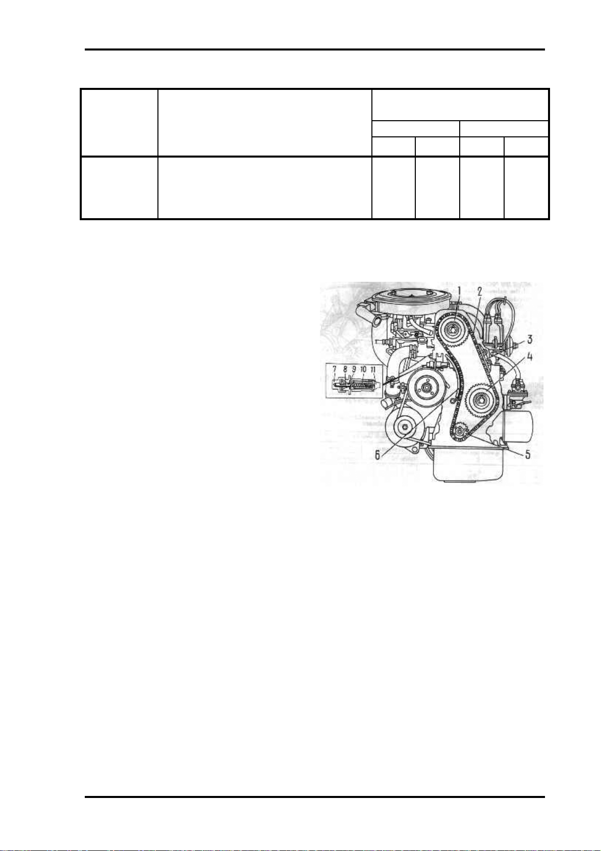
The mechanisms, units and parts subject to scheduled maintenance are indicated by reference
numbers in Figs 25 and 26. Table 1 contains the lubricating instructions and Table 2,
maintenance instructions (cleaning, checking and adjustment).
The car should be serviced every 10,000 Km. However, during the initial period of operation,
when working-in of all the units and mechanisms takes place, the car should be serviced after
covering the first 2,000-3,000 Km. This will ensure superb performance and long service life
of the car.
The list of the tools and accessories delivered with the car for Owner’s services is given in
Appendix 3.
ENGINE LUBRICATION
Oil Sump
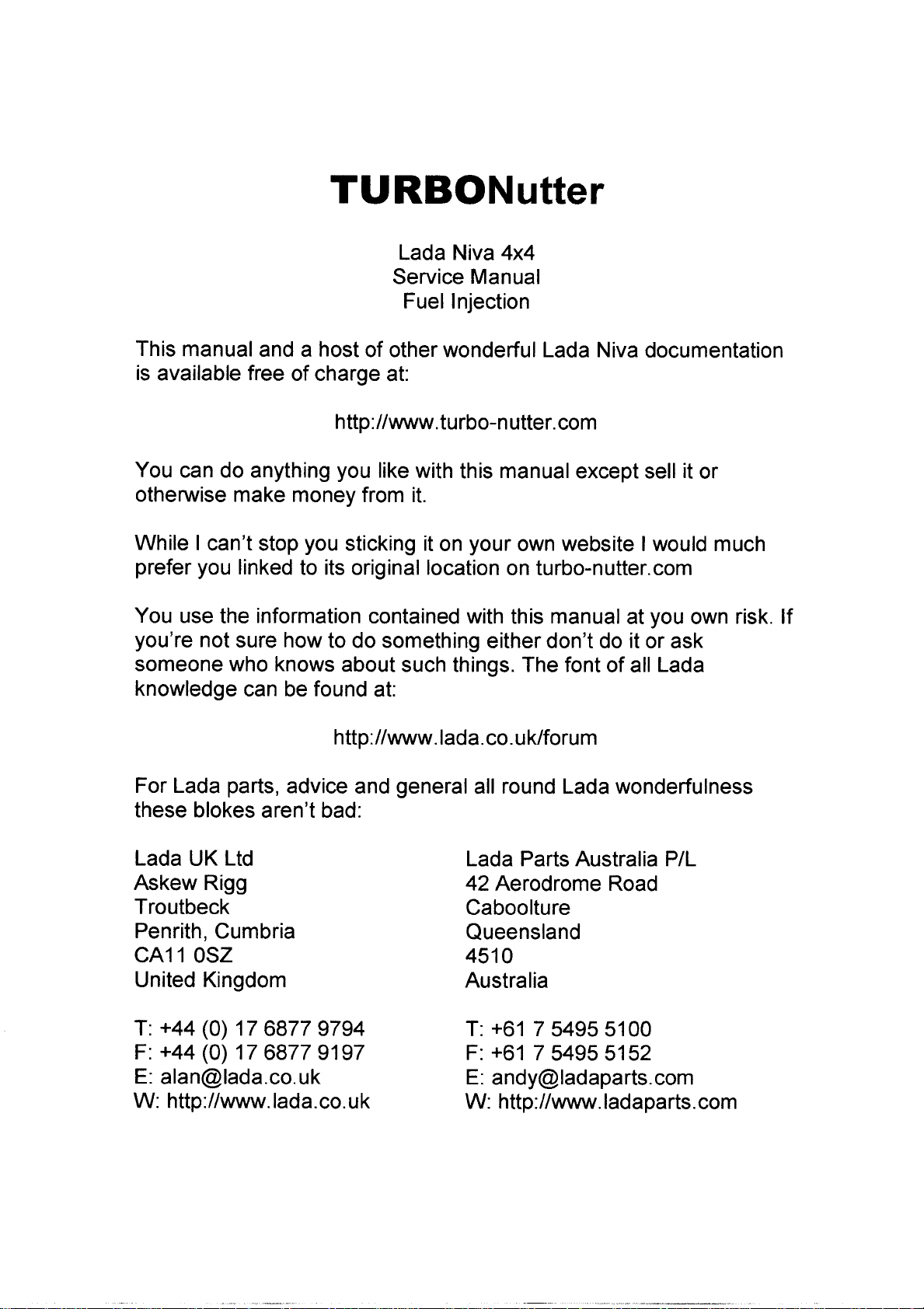
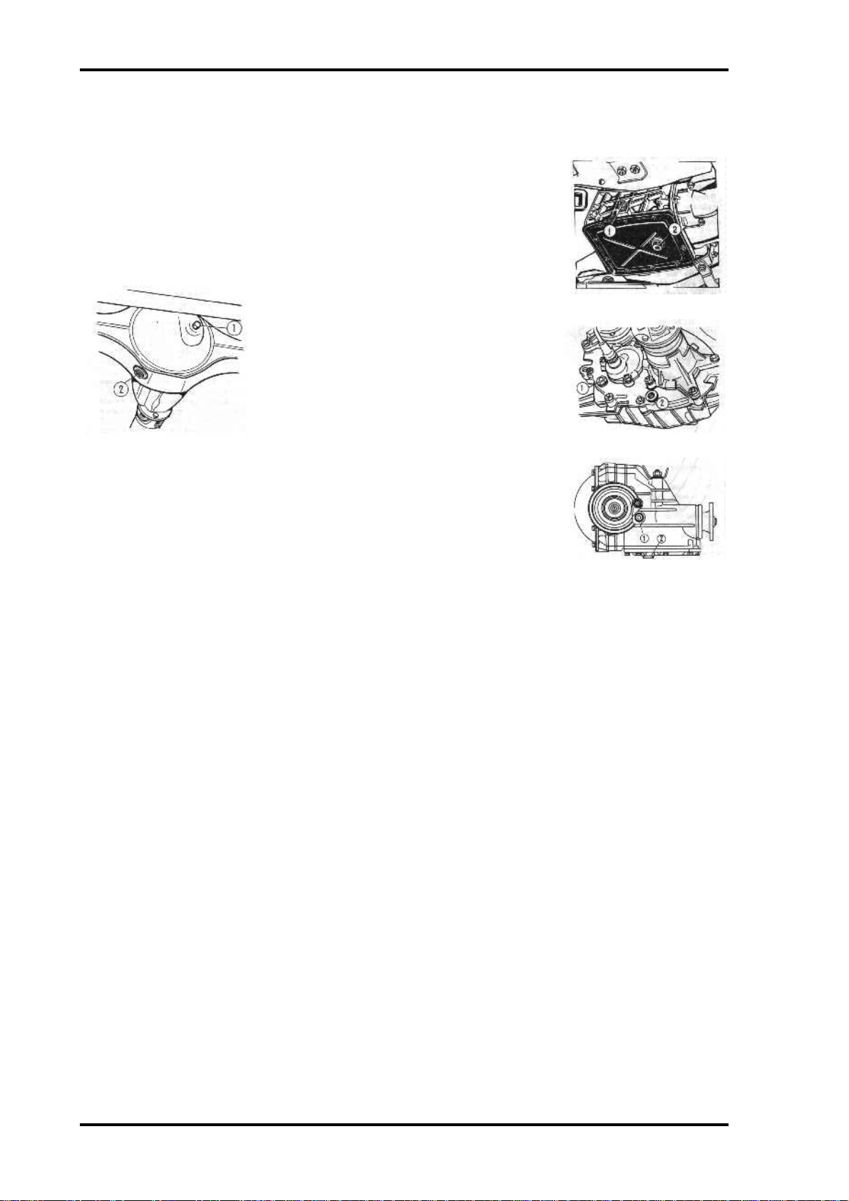
Every 500 Km check the oil level in a cold engine and add oil, if
necessary. The oil level should be between marks MIN and MAX on
oil dipstick 1 (Fig. 27).
On a new engine change oil after the first 2,000-3,000 Km, then at
10,000 Km and thereafter every 10,000 Km. Change oil while the
engine is still hot. Drain used oil after removing the plug of the hole
in the bottom of the engine sump. Pour fresh oil through oil filler
neck 2, located on the cylinder head cover.
The seasonal change of oil depends on the change of season as
different temperature conditions call for the employment of different grades of oil (see
Appendix 2).
Every 30,000 Km wash the lubricating system. Wash the system earlier only when sticky
gum deposits accumulate on the camshaft housing.
Perform this operation on a hot engine as follows:
• Drain used oil from the engine sump.
• Fill the engine with a special detergent oil, to the MIN mark and let the engine run idle at a
speed of about 1,000 rpm for 10 minutes.
• Drain the detergent oil, replace the oil filter and pour in fresh oil of the grade recommended
for the season.
note. When using equivalent oils produced by different firms, wash the lubricating system
each time before the oil change.
Page 4
Lada Niva Manual - Maintenance Page 3
Oil Filter
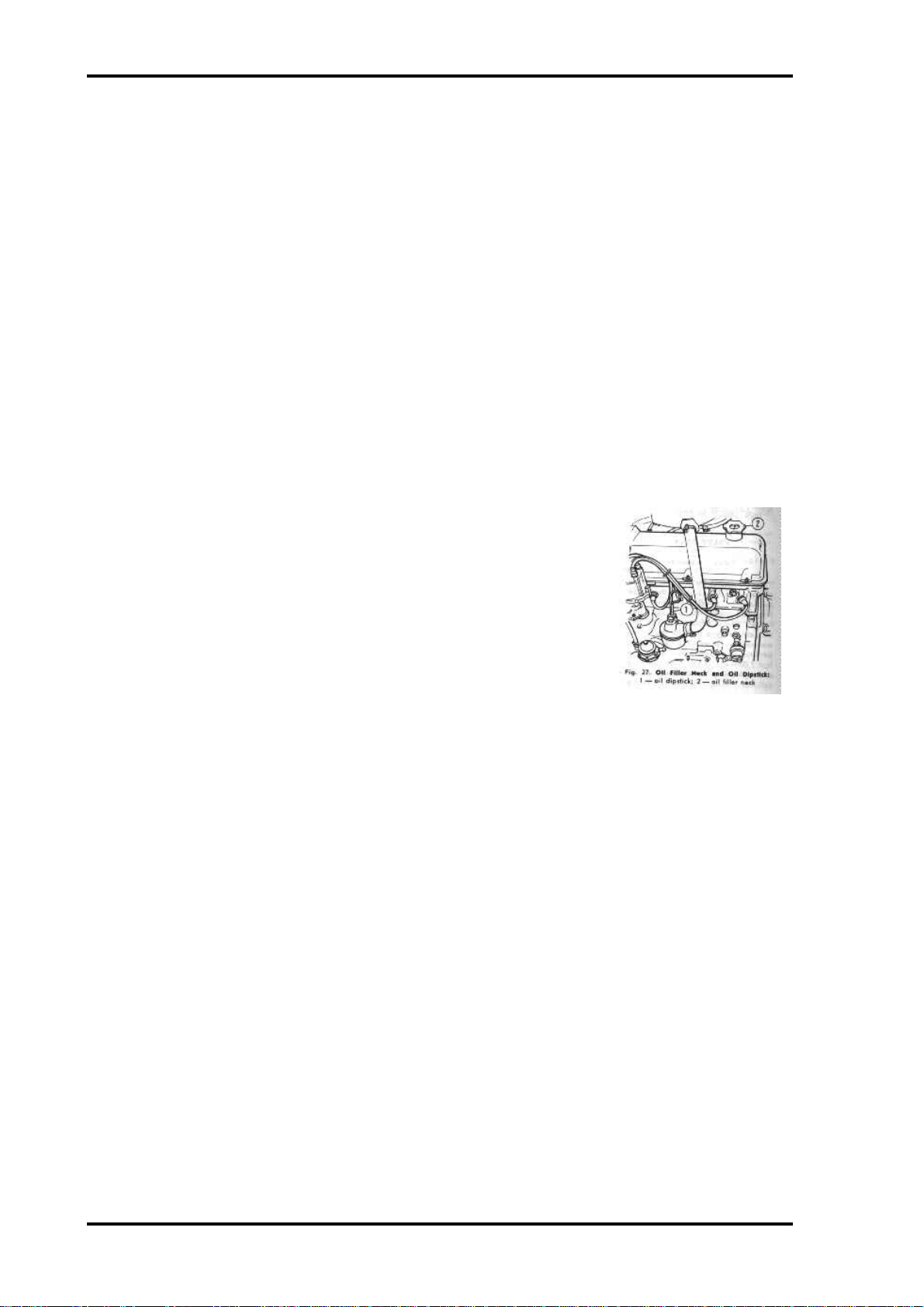
Every 10.000 Km replace the filter. Do it after the first 2,0003,000 Km on a new car. To replace the filter unscrew it from the
cylinder block (pig. 28). Screw the new filter in place only handtight.
Page 5
Lada Niva Manual - Maintenance Page 4
VALVE GEAR
Valve Clearances
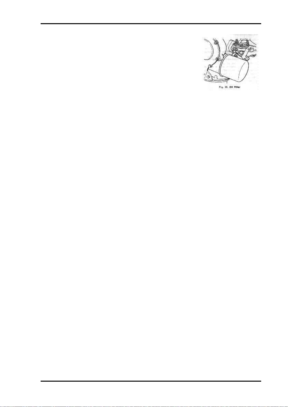
Every 10.000 Km and also in case of abnormal knocking in the
valve mechanism, check clearances A (Fig. 29) between the
cams and valve rockers which should be 0.15 mm on a cold
engine both for the intake and exhaust valves. On a new engine
perform this operation after the first 2,000-3,000 Km upon
checking and tightening the fasteners of the cylinder head,
camshaft bearing housing and intake and exhaust manifolds.
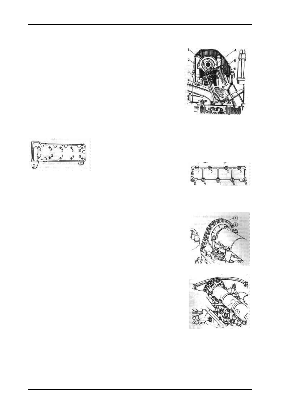
Loosen the cylinder head bolts preliminarily through about
30" each and then tighten them according to the sequence
shown in fig. 30.
A - Valve rocker to cam clearance 1 cam, 2 - valve rocker, 3 - valve oil
deflecting cap, 4 - valve, 5 - rocker
adjusting bolt, 6 - adjust bolt locknut.
Valve Gear
Tighten bolts 1 through 10 to a torque of 115 NÆm (11.5 kg Æ m),
and bolt 11 to a torque of 38 NÆm (3.8 kg Æ m).
Tighten the nuts of the camshaft
Figure 30 - Sequence of tightening
cylinder head bolts
sequence shown in pig. 31.
bearing housing by applying a torque
of 22 NÆm (2.2 kg m) according to the
Fig 31. Sequence of tightening
camshaft bearing housing nuts
To adjust the valve clearances, proceed as follows:
• Remove the cylinder head cover with its gasket; if necessary,
first remove the heater air intake box;
• Rotate the crankshaft clockwise to align mark A (Fig. 32) on
the sprocket with mark B on the camshaft housing; in this case
the piston of the No. 4 cylinder will be on TDC at the end of
the compression stroke, and both valves will be closed
• Adjust the rocker-to-cam clearances of the exhaust valve on
the No. 4 cylinder (8th cam) and of the intake valve on the No.
3 cylinder (6th cam); for this purpose, loosen locknut 2 (Fig.
33) and rotate adjusting bolt 1 to set the required clearance,
using a flat feeler gauge inserted between the cam and the
rocker (the feeler gauge should move in this case with a slight
biting)
• Holding bolt 1 in this position with a wrench, tighten locknut
2 by applying a torque of 52 NÆm (5.2 kg Æ m) and recheck the
clearance
• Turning the crankshaft each time through hall a revolution,
adjust the clearances of other valves, following the sequence
given in Table 3 below.
Fig 32.
Setting No. 4 Cylinder piston in TDC
Fig 33. Adjusting valve clearances:
1- adjusting bolt, 2- adjusting bolt
locknut
Page 6
Lada Niva Manual - Maintenance Page 5
Table 3 - Sequence of Valve Clearance Adjustment.
Crankshaft No of cylinder in which piston is on
Valves under adjustment
TDC
angle at end of compression stroke exhaust intake
degrees
Cylinder
No.
Cam No. Cylinder
No.
Cam No.
0 4 4836
180 2 2447
360 1 1123
560 3 3512
• Reinstall the cylinder head cover with its gasket. Adjustment over, check the tightening
torque of the crankshaft jaws, which should be 122 NÆm (12.2 kg Æ m).
Tensioning the Valve Gear Chain
Every 10.000 Km, adjust the tension of
timing chain 2 (Fig. 34). Do it on a new car
after the first 2,000- 3,000 Km. For this
purpose, loosen retaining nut 7 and turn the
crank- shaft through 1-1~5 revolutions in the
direction of its normal rotation. In this case
spring 10 actuates shoe 6 through plunger 11
and automatically sets the required chain
tension. Adjustment over, tighten nut 7.
Adjust chain tension also in case of excessive
operation noise in the valve gear.
Fig 34. Valve Gear Drive. 1 - camshaft sprocket, 2 - chain, 3 dampener, 4 - oil pump drive shaft sprocket, 5 - crankshaft
sprocket, 6 - chain tensioner shoe, 7 tensioner rod retaining nut, 8 retainer, 9 - tensioner adjusting rod, 10 - plunger spring, 11 tensioner plunger
FUEL SYSTEM
Page 7
Lada Niva Manual - Maintenance Page 6
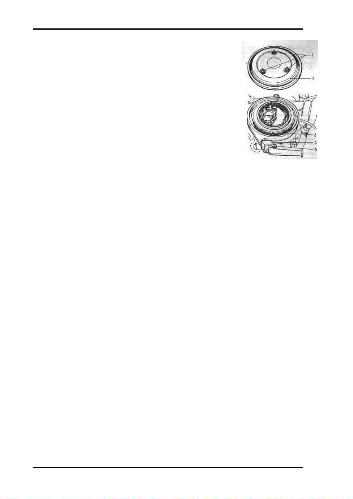
Air Cleaner
Every 10.000 Km replace filter element 3 (Fig. 35); to this end
unscrew nuts 1 and remove cover 2. When driving on extremely dusty
roads, replace the filter element every 5,000 Km.
Seasonal adjustment of the air cleaner is required for delivery of fresh
or warm air (warmed by the exhaust manifold). If the average ambient
temperature in the season is below 15 "C, slightly pull and then shift
the handle 5 of the gate on the housing of thermo-regulator 4 in the
upper position (HOT) and if the average temperature is above 15 "C,
shift the handle to the lower position (COLD).
Figure 35. Air Cleaner 1- nut, 2cover, 3- filter, 4- thermo-regulator, 5handle
Page 8
Lada Niva Manual - Maintenance Page 7
Carburettor
Every 10.000 Km (and also after the first 2,0003,000 Km if the car is new), wash the carburettor
fuel filter and the fuel pump filter with gasoline and
blow them out with compressed air.
Every 20,000 Km clean the carburettor from the
inside, wash it with gasoline or benzene and blow
out with compressed air. When cleaning the
calibrated orifices of the jets, use a wooden stick or
match with a pointed end wetted with acetone. Do
not use wire, even soft, not to disturb the
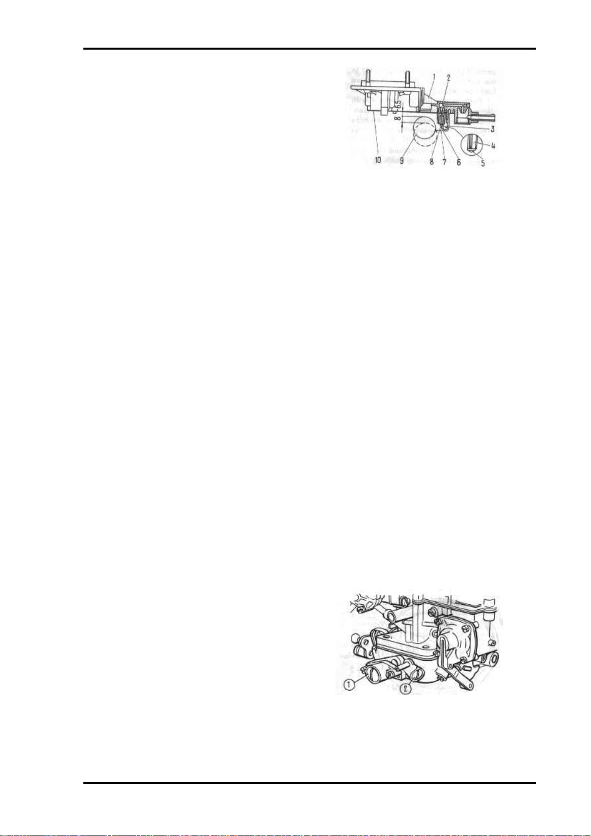
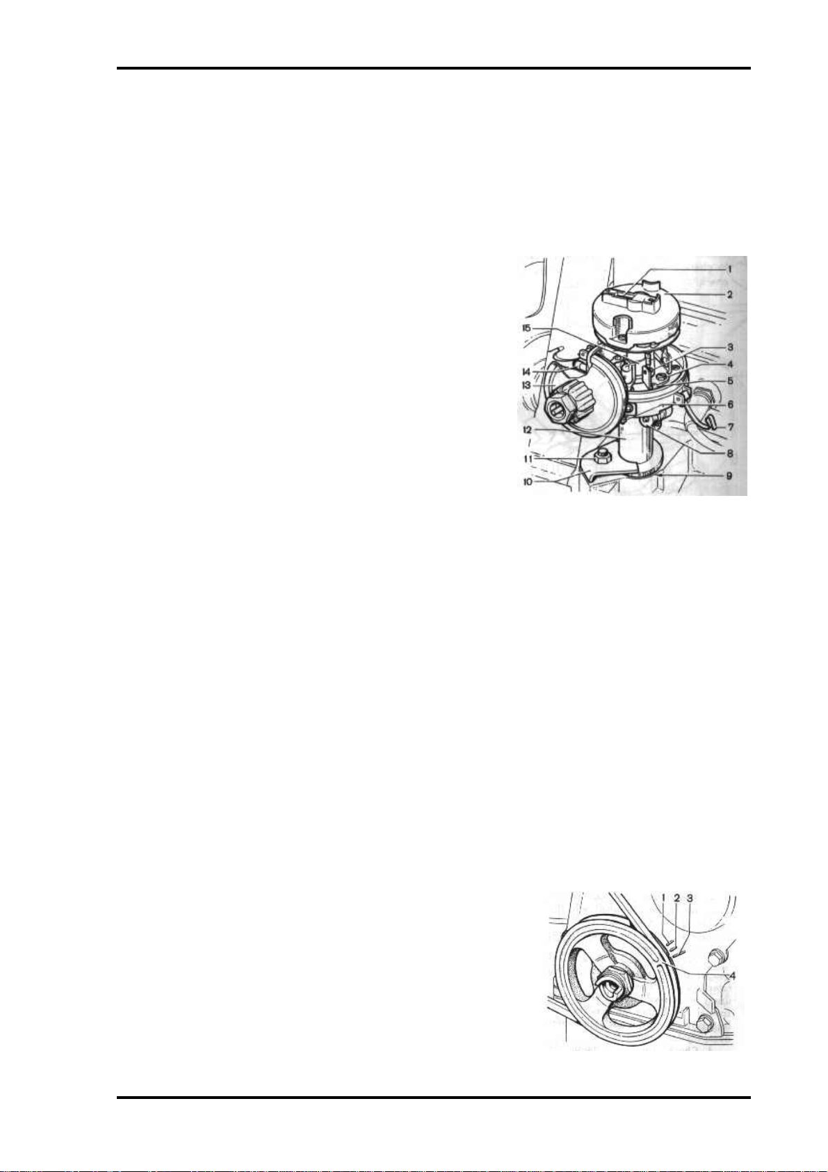
Fig. 36.Adjusting Fuel Level In Carburettor
Float Chamber: 1- carburettor upper body, 2 -
needle valve rest, 3 - stop, 4 - needle valve, 5ball, 6- pull-back yoke, 7 arm, 8 lounge, 9float, l0- gasket.
dimensions and finish of the orifices. When screwing the jets in or out, avoid damaging the
thread in the holes.
Check and, if necessary, adjust the fuel level in the float chamber and the float travel, for
which purpose.
• Make sure that the mass of float 9 (Fig. 36) complete with arm 7 is 12+1 g, the float has no
holes or dents, and can freely rotate on its pin.
• Make sure that seat 2 of needle valve 4 is tightened reliably and that damper ball 5 built
into needle valve 4 does not stick
• Set upper body 1 vertically so that the fuel inlet union is directed upwards, the needle
valve is closed, and float tongue 8 lightly contacts the needle valve ball.
• With the parts in this position, measure the distance between the float and the surface of
gasket 10 which fits the upper body; the distance should be 6.5 mm
• Change the position of the tongue, if necessary, to obtain the required distance; the tongue
must be perpendicular to the valve axis, and the contacting surface of the tongue should
have no defects that may cause sticking of the valve.
• Check the float travel which should be 8 mm, changing the position of stop 3, if necessary.
• Check that pull-back yoke 6 of the needle valve does not interfere with free travel of the
valve.
• Reinstall the carburettor upper body after making sure that the float is free to move
without brushing against the chamber walls.
Note. When replacing the needle valve, also replace the gasket between the seat and the upper
body.
Idling speed adjustment
Every 10.000 Km (and also after the first 2,0003,000 Km if the car is new), adjust the minimum
idling speed of the engine. Have this adjustment
done at a service station. The Owner is allowed
only to carry out fine adjustment of the engine
idling speed within the range permitted by idle
speed screw limiting bushing 1 (Fig. 37) and by
idle mixture screw limiting bushing 2. Attempts to
turn the bushings through a larger angle will
Fig 37. Idling system adjustment screws: 1- Idle
speed screw limiting bushing, 2- idle mixture screw
limiting bushing.
destroy them. In this case the Manufacturer bears
no responsibility for excessive content of carbon monoxide (CO) in the exhaust gases and for
excessive fuel consumption.
Page 9

Lada Niva Manual - Maintenance Page 8
Perform the fine adjustment with the engine warmed-up, valve clearances adjusted, and a
spark advance angle set properly. Proceed as follows.
• Start the engine and turn idle mixture screw limiting bushing 2 all the way out.
• Using idle speed screw limiting bushing 1, set the engine speed within 850-900 rpm
Page 10
Lada Niva Manual - Maintenance Page 9
Check the engine idling performance. For this purpose, abruptly depress and release the
accelerator pedal; in this case the engine speed should increase smoothly without missing. The
engine should not stall when the idling speed is reduced to minimum. If the idling speed fine
adjustment fails to ensure normal running of the engine without missing, apply to a service
station for a qualified help.
CRANKCASE BREATHING SYSTEM
Every 20.000 Km clean and wash with gasoline the hoses of the crank- case breathing
system, the shut-off valve on the carburettor throttle valve shaft, and the flame arrester
located in the exhaust hose running from the engine to the air cleaner.
COOLING SYSTEM
Coolant
The cooling system of the cars leaving the plant is filled with
special fluid A-40M. This fluid is an ethylene glycol mixture with
a freezing point of minus 40"C and anticorrosive, antifoaming and
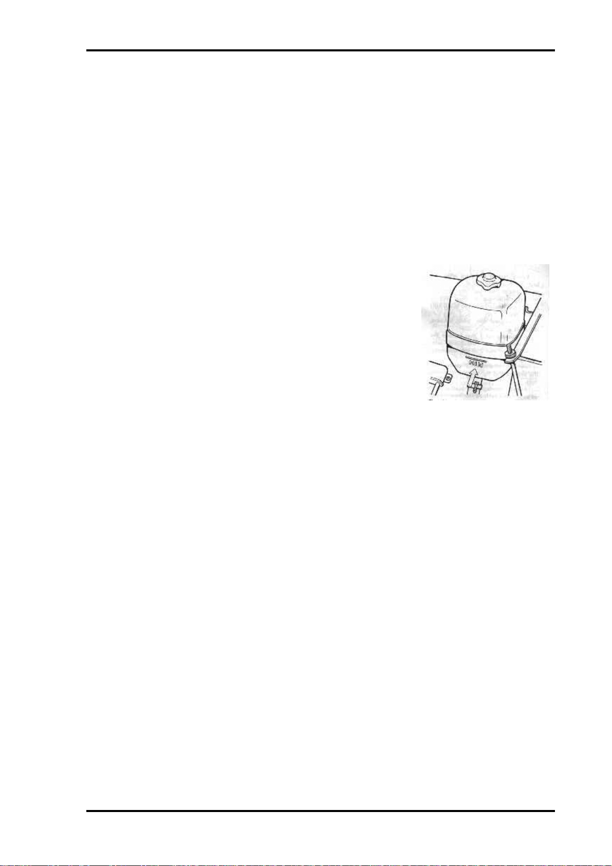
antiscaling properties. It needs no replacement within a period of
three years. Therefore, care of the cooling system during this
period consists only in checking at regular intervals the fluid level
in the expansion tank.
The fluid level should always be 3-4 cm above the MIN mark
Fig 38 Cooling system expansion tank
(Fig. 38). Check the fluid level on a cold engine only, since when
the engine is hot the level may rise significantly; expansion of the fluid volume may also take
place immediately after engine shutdown.
If the fluid level is below the MIN mark, replenish the expansion tank with fluid of the same
grade. If the coolant level drops constantly and frequent replenishments are required, check the
cooling system for leakage and eliminate the trouble. In an emergency the cooling system may
be filled with clean water. In this case proceed as follows:
• Cool the engine.
• Remove the caps from the radiator and expansion tank.
• Pour water into the radiator (keep pouring water until it starts flowing out of the radiator
filler neck).
• Reinstall the radiator cap.
• Add water into the expansion tank until its level is 3-4 cm above the MIN mark.
• Reinstall the expansion tank cap.
In cold seasons if water has been added into the cooling system and before placing the car in
motion, warm the engine up to 85-90"C to make the fluids mix. Bear in mind that water added
into the cooling system raises the freezing temperature of the mixture; therefore, per- form the
necessary repairs of the cooling system at the first opportunity and fill it with the coolant of
the prescribed grade.
Page 11
Lada Niva Manual - Maintenance Page 10
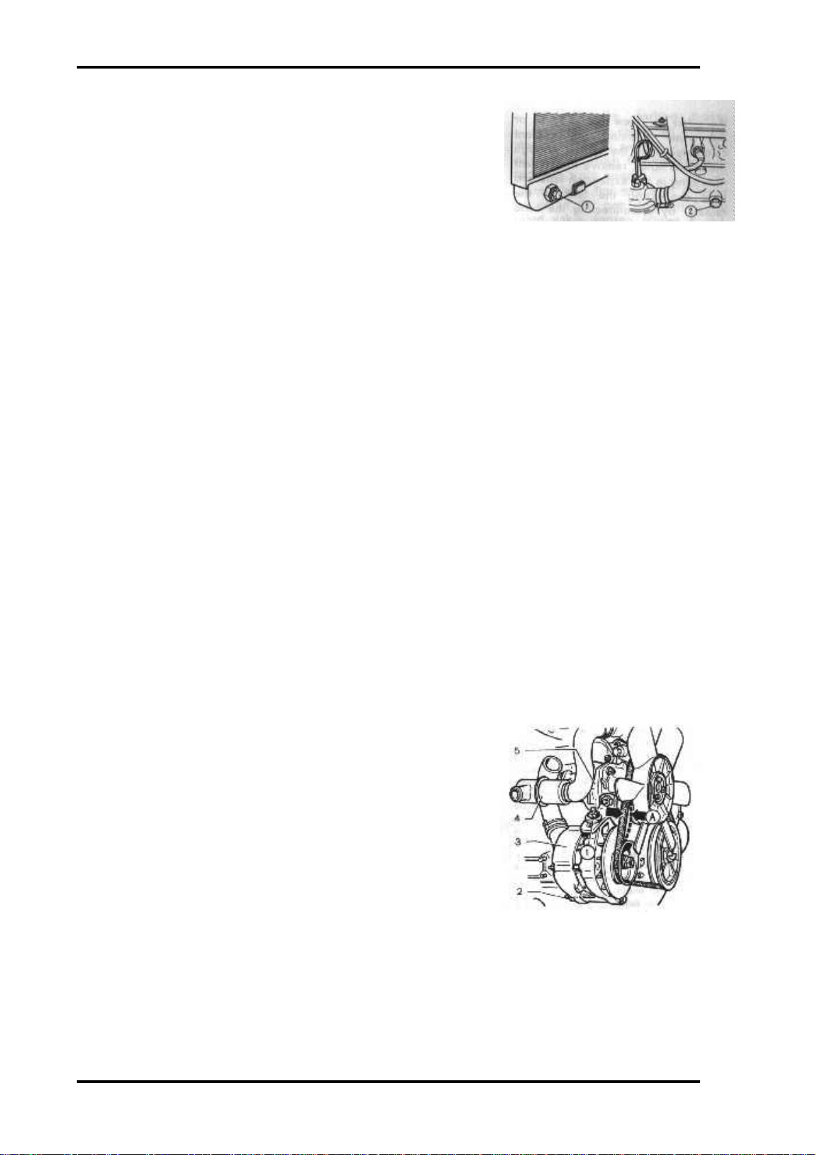
Every three years or every 60,000 Km (whichever comes
first), flush the cooling system and fill it with fresh coolant.
Drain coolant from the system through two drain holes 1 and
2 (Fig. 39), one of which is located in the radiator bottom tank
and the other one in the cylinder block at the left side. In doing
so shift the heater cock control lever to the right most
position.
Fig 39. Cooling system drain holes. 1- drain hole
in radiator bottom, 2- drain hole in cylinder block.
For screwing the radiator drain hole plug in or out, use two wrenches; one to keep in place
the plug union soldered into the radiator tank, and the other to screw the plug in or out. After
draining the coolant completely from the system through the above holes, remove the coolant
remaining in the expansion tank and hose connecting the tank to the radiator by disconnecting
the hose from the expansion tank or by raising the tank proper to a required height.
To flush the cooling system, proceed as follows.
• Fill the system with clean water, start the engine and run it until the bottom tank of the
radiator gets warmed and, with the engine idling, drain water through the radiator and
cylinder block drain holes.
• Let the engine cool down, refill the system with clean water and repeat the above
operation.
After the flushing pour coolant into the cooling system. If the coolant of the specified grade
is not avail- able, it is permissible (at ambient temperatures above zero) to use clean water, as
soft as possible to avoid heavy scale deposition which leads to engine overheating under
normal operating conditions. When using hard water, flush the cooling system twice a year
with special descaling agents.
If an aluminium radiator is in- stalled in the car do not use water in the cooling system as
water affects corrosion resistance of the radiator.
Cooling System Thermostat
Every 20.000 Km and also in case of abnormal temperature
of the engine (overheating under normal operating conditions
or excessively long warm-up period after starting), check
thermostat 4 (Fig. 40) for normal functioning. A simple check
is the hand- feeling of the thermostat directly on the car.
Upon starting the cold engine with the thermostat serviceable, the bottom tank of the radiator starts getting warm as
soon as the coolant temperature is 80-85 "C.
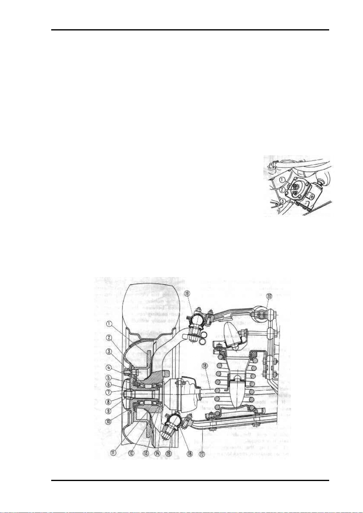
Alternator Drive Belt
Fig 40. Checking tension of Alternator
drive belt. 1- nut, 2- nut of alternator joint
pin, 3- alternator, 4- thermostat, 5- water
pump, A- belt deflection.
Every 10.000 Km (and after the first 2,000-3,000 Km if the car is new), check the belt for
tension. Normal deflection A (Fig. 40) is 10-15 mm if a force of 100 N (10 kg) is applied.
To increase the belt tension, proceed as follows.
• Loosen nut 1 that fastens the alternator to the adjusting arm.
Page 12
Lada Niva Manual - Maintenance Page 11
• Loosen nut 2 of the alternator joint pin.
• Shift alternator 3 away from the engine and tighten the fastening nuts.
Avoid over tightening the belt so as not to overload the bearings of alternator 3 and water
pump 5.
IGNITION SYSTEM
Ignition Distributor
Every 10,000 Km:
1. Check the working surfaces of breaker contacts 3 (Fig.
41). In case of heavy transfer of metal from one
contact point to the other, dress them with a flat
barette file. Do not eliminate completely the crater on
the breaker arm contact point. Check and, if necessary,
dress the contacts in the distributor cap and on the
rotor.
2. Use a piece of clean, gasoline- soaked chamois leather
or some other lint-free material to clean the breaker
contact points, the rotor, and the outer and inner
surfaces of the distributor cap.
3. Check the breaker point gap which should be 0.4+0.05
Figure 41. Ignition distributor. 1- noise resistor
suppressor, 2- rotor, 3- breaker contacts, 4screw, 5- slot, 6- terminal, 7- spring catch, 8capacitor, 9- scale, 10- bracket, 11- nut, 12- body,
13- vacuum spark timer, 14- lubricator, 15- cam
mm, for which purpose.
• Shift the gearshift lever into the neutral.
• Apply the parking brake;
• Rotate the crankshaft with the starting crank to set cam 15 in the position at which the
breaker contacts are wide open.
• Check the gap with a feeler gauge; if the gap differs from the rated value, loosen screws 4
and, using a screwdriver inserted into special slot 5, shift the breaker con- tact post as
required; adjustment eve, tighten screws 4.
4. Check ignition timing, for which purpose
• Connect one end of the wire of a 12-V test lamp to terminal 6, and ground its other end.
• Turn on the ignition and slowly rotate the crankshaft with the starting crank; with the
ignition set properly, the test lamp should come on when mark 4 (Fig. 42) on the
crankshaft pulley is aligned with mark 2 on the timing gear cover, and the contact of rotor 2
(Fig. 41) should be opposite the contact of the No. 1 cylinder on the distributor cap.
5. If the marks are not aligned at the moment the test lamp
comes on, adjust the ignition timing as follows.
• Rotate the crankshaft with the starting crank to set it in
the position at which the rotor contact faces the contact of
the No. 1 cylinder on the distributor cap, and mark 4 (Fig.
42) is aligned with mark 2 (in this position the piston of
the No. 1 cylinder will be 5" before TDC as measured in
crankshaft degrees);
• Loosen nut 11 (Fig. 41) and turn distributor body 12
clockwise until the breaker points are closed.
Fig 42. Timing marks on pulley and valve
gear drive cover. 1- 10o, 2- 5 o, 3-0 o, 4-
mark on pulley
Page 13
Lada Niva Manual - Maintenance Page 12
• Slowly rotate the distributor body counter-clockwise until the test lamp comes on; in doing
so, slightly press the rotor counter- clockwise to take up clearances.
• Stop the distributor body exactly at the moment the test lamp comes on (the breaker
contact points are at the beginning of opening phase).
• Holding the distributor body in this position, tighten nut 11.
• Switch off the ignition, install the distributor cap on its body, and secure it with two spring
catches 7.
On a new car, check the breaker point gap and ignition timing after the first 2,000-3,000 Km.
Every 20.000 Km deliver 2-3 drops of engine oil into the hole of lubricator 14.
Spark Plugs
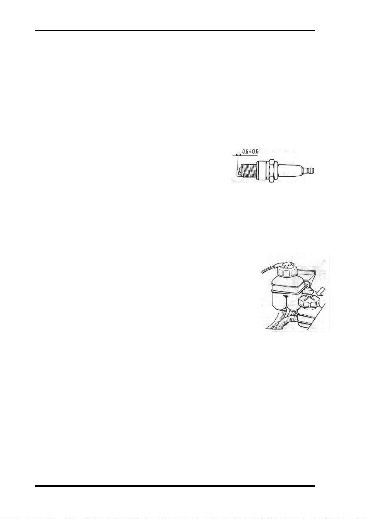
Every 10,000 Km proceed as follows:
1. Using gasoline and a stiff brush, remove carbon deposit
from the spark plugs.
2. 2. Check the spark plug gap with a round wire feeler gauge.
The gap should be 0.5-0.6 mm (Fig. 43); the gap must be
Fig 43. Checking spark plug gap
adjusted only by bending the side electrode.
Every 20,000 Km replace the spark plugs with new ones. For re- liable starting of the engine
at low sub-zero temperatures, it is recommended to replace the long-used spark plugs with
new ones, even if the used spark plugs are still serviceable; they can be used again in warm
seasons of the year.
TRANSMISSION
Clutch Fluid Reservoir
Every 10,000 Km check fluid level in the reservoir (Fig. 44) and
replenish, if necessary, to the lower edge of the filler neck.
Add HeBa (Neva) or Tomb (Tom) brake fluid only. It is recommended
to change the brake fluid with fresh one after five years of service.
Adjusting the Clutch Control Mechanism
Every 30,000 Km (and also after the first 2,000-3,000 Km and 10,000 Km if the car is new)
check and, if necessary, adjust the clutch control mechanism for which purpose.
Page 14
Lada Niva Manual - Maintenance Page 13
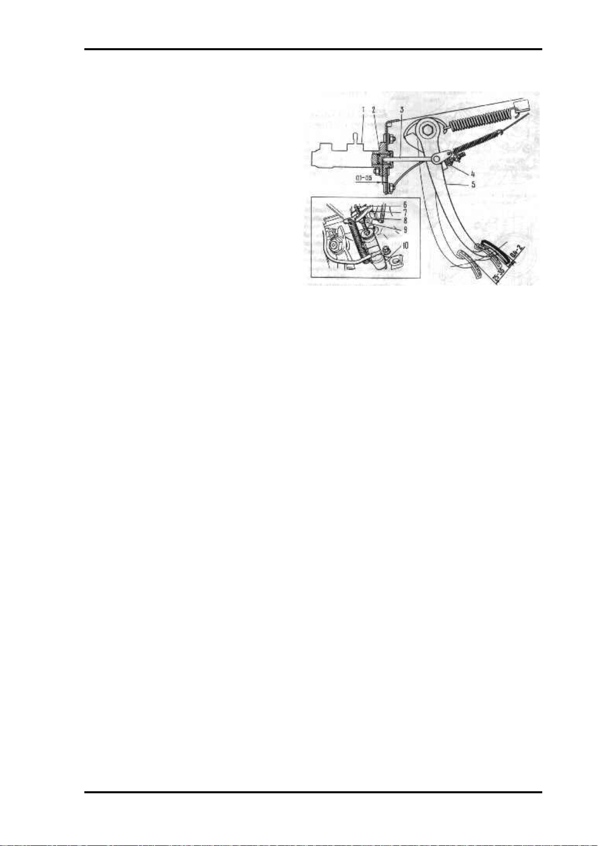
Check clearance between pushrod 3 (Fig. 45) and piston 2 of master cylinder 1 which should
be 0.1-0.5 mm. The clearance corresponds to the travel of pedal 5 through 0.4-2 mm and it is
adjusted with stop 4.
Check free travel of pushrod 6 of
operating cylinder 10 which should be 4-5
mm. Pushrod free travel is adjusted with
nut 8 after loosening locknut 9.
Adjustment over, tighten locknut 9.
Upon completion of the above
adjustments free travel of the clutch pedal
before the beginning of clutch release
should be 25-35 mm. Check the clutch
pedal free travel also after the bleeding of
the hydraulic control system. Presence of
air in the system is indicated by the
spongy pedal and incomplete release of the
clutch (clutch drags). Bleed the system
through the union of operating cylinder 10
Fig 45. Adjusting Clutch control mechanism. 1- Clutch master
cylinder, 2- pushrod piston, 3- pushrod, 4- pedal travel stop, 5- clutch
pedal, 6- operating cylinder pushrod, 7- clutch release fork, 8- nut, 9locknut, 10- operating cylinder.
in the same way as the brake system.
Page 15
Lada Niva Manual - Maintenance Page 14
Gearbox, Transfer Case.
Front and Rear Axles
After the first 2000-3000 Km and every 30.000 Km, change oil in
the gearbox, transfer case, and front and rear axles. Do it right after
the trip, when oil is still hot. Drain used oil through the holes closed
with plugs 2 (Figs. 46, 47, 48, 49). Pour fresh oil through the level
check holes closed with plugs 1, up to the lower edges of these
holes.
Fig 46. Gearbox. 1- check hole
Every 10,000 Km check oil level which
plug, 2- drain hole plug
should reach the lower edges of the level
check holes. Check be- fore the trip to be
sure that all oil has dripped down from
the walls and gears.
Fig 49. Rear Axle. 1- check hole
plug, 2- drain hole plug.
Propeller Shaft Splined Connections and Crosses
Fig 47. Transfer Case. 1- check
hole plug, 2- drain hole plug
Every 10.000 Km deliver grease to the splined connections through
the grease fittings and grease-gun the crosses with grease No. 158 or
Fig 48. Front Axle. 1- check hole
plug, 2- drain hole plug
cDMOn-ZY till fresh grease shows up under the seals.
Joints of Front Wheel Drive Propeller Shafts
While in service, care of the joints of the front wheel drive propeller shafts is confined only
to regular checking the condition of protective boots. A damaged boot should be immediately
replaced with a new one upon washing the joint and changing the grease. This operation
should be performed at a service station.
HYDRAULIC SHOCK ABSORBERS AND ANTIROLL BAR
Every 30.000 Km check the shock absorbers for serviceability. If the shock absorbers
operation becomes less efficient, which is manifested by slow damping of oscillations (3-4
oscillations) of the car body on crossing a road bump, or by unusual knocking in the shock
absorbers, apply to a service station. Pay attention also to the condition of shock absorber
rubber bushings and rubber cushions of the antiroll bar. If the rubber bushings and cushions
show any signs of damage or age-hardening, replace them with new ones.
STEERING GEAR AND WHEELS
Steering Gear Clearances
Every 20,000 Km (and also after the first 2,000-3,000 Km if the car is new), check the
steering wheel for play which should not exceed 18-20 mm measured on the wheel rim with
the wheels in the straight ahead position and with normal clearances in the steering gear. If the
steering wheel play exceeds this value, perform an overall check of the steering gear:
Page 16
Lada Niva Manual - Maintenance Page 15
1. Make sure that the bearings of the front wheel hubs are adjusted properly and the tyre
inflation pressure is normal.
2. Turning the steering wheel in either direction, check for knocking in the joints, steering
mechanism and connections. Check and tighten, if necessary, the fastenings of the pitman
arm, steering gear case, brackets of the idler arm and steering shaft.
3. Rocking the steering wheel hand-feel the steering rod ball joints for play.
4. Make sure the ball supports and the joints of the front suspension wishbones are in
serviceable condition.
5. Eliminate the faults detected and check steering wheel play. If steering wheel play exceeds
the permissible value, check and adjust the following clearances in the steering mechanism:
Clearance in the worm bearings that is found by axial movement of the
steering shaft while turning the steering wheel leftward and rightward
through a small angle; eliminate the clearance by decreasing the number
of shims 3 (Fig. 50) placed between the case and the thrust bearing
cover until the shaft rotates easily without axial displacement;
Roller-to-worm backlash which is found by rocking the pitman arm
head, with the rods disconnected, with the car wheels in the straight
ahead (neutral) position; eliminate backlash by turning in screw 1,
Fig 50. Adjusting clearances in
steering mechanisms. 1- screw, 2-
nut, 3- shims
with nut 2 loosened and the pitman arm in the neutral position;
adjustment over, tighten nut 2; there should be no backlash between the roller and worm when
the steering wheel is turned through 30" to the right or to the left from the neutral position.
Front Wheel Hub Bearings
Fig. 51. Front Wheel: 1 - brake disc; 2 - hub; 3 - outer roller bearing; 4 - outer seal protective ring; 5 - outer seal; 6 tapered bushing; 7 - hub nut; 8 - hub cap; 9 - propeller shaft drive end; 10 - outer seal demounting ring; 11 - inner
roller bearing; 12 - inner seel demounting ring; 13 - inner seal; 14 - inner real protective ring; 15 - steering knuckle;
Page 17

Lada Niva Manual - Maintenance Page 16
16 - lower wishbone ball support; 17 - lower wishbone; 18-propeller shaft; 19-upper wishbone ball support; 20 shims
Every 10.000 Km (and also after the first 2,000-3,000 Km if the car is new), check and
adjust, if necessary, the clearances in the front wheel hub bearings. For this purpose, proceed
as follows:
• Place the car on a level ground, apply its parking brake, loosen the wheel fastening nuts,
jack up the wheel and remove it, having turned off the wheel nuts
• Remove hub cap 8 (Fig. 51), secure a device with an indicator on steering knuckle 15 so
that the indicator finger contacts the end face of hub 2 near the tapered hole;
• Pull the hub to yourself by hands, and set the indicator pointer to zero;
• Measure the clearances in the hub bearings, for which purpose push the hub axially away
from your- self. If in this case the indicator readings exceed 0.15 mm, adjust clearances in
the bearings in the following way;
• Remove the indicator, screw off nut 7 and replace it with a new one;
• Tighten nut 7 to a torque of 20 NÆm(2 kg m), rotating the hub in both directions;
• Loosen the nut and retighten it to a torque of 7 N Æ m (0.7 kg Æ m); then, screw it off
through 20-25";
• Install the indicator and measure clearances in the bearings. If clearances exceed 0.07 mm,
repeat the adjustment. If clearances are within 0.01-0.07 mm, fix nut 7 by staking the dents
on the nut shoulder into the slots on drive end 9 of the propeller shaft.
• Remove the device with the indicator, install cap 8, fasten the wheel, jack down the car, and
tighten the wheel nuts all the way home.
Every 20.000 Km. replace grease in the bearings of the front wheel hubs. For this purpose
proceed as follows.
• Remove the wheel, disconnect the brake calliper from steering knuckle 15, and take it off
brake disc 1;
• Remove hub cap 8, screw off nut 7, take out tapered bushing 6 and remove hub 2 complete
with brake disc 1;
• Place a support under lower wishbone 17 and screw off the nuts securing ball support 16
to the wishbone;
• Disconnect the shock absorber from the lower wishbone and the side steering rod from the
arm of steering knuckle 15;
• Shift propeller shaft 18 to- wards the front axle as far as it will 90;
• Turning steering knuckle 15 about upper wishbone ball support 19, remove the former
from the propeller shaft drive end;
• Use the puller to remove the cones of bearings 3 and 11 with demounting rings 10 and 12
and seals 5 and 13 from the steering knuckle space. Mark the bearing cones in order to
reinstall the cones in their proper places during the assembly;
• Remove the used grease and wash with kerosene the inner space of the steering knuckle,
outer and inner spaces of the hub, propeller shaft drive end, and bearing cones;
• Pack 40 g of fresh grease nHTon-24 into the bearing cages, apply a uniform layer of grease
to the steering knuckle spaces between the bearings, and lubricate the splines of the
propeller shaft drive end;
• Reinstall the bearing cones and demounting rings, and press- fit the seals;
Page 18

Lada Niva Manual - Maintenance Page 17
• Mount the steering knuckle on the propeller shaft drive end, connect the ball support to
the lower wishbone, secure the shock absorber, and connect the side steering rod to the
steering knuckle arm;
• Install the hub complete with the brake disc on the propeller shaft drive end, and install
tapered bushing 6; screw on new hub nut 7 and adjust bearing clearances, as described
above;
• Fit the hub cap, remove the support, install and secure the brake calliper, and reinstall the
wheel.
• If the car is frequently driven on bad roads (deep mud), change grease every 10,000 Km.
Examining the Front Suspension Ball Supports and Steering Rod joints
If tyre inflation pressure and clearance in the front wheel hub bearings correspond to the
rated values, the joints of the front wheel suspension wishbones are in good condition, the
pitman arm, steering gear case, idler arm brackets and steering shaft are fastened securely, but
adjustment of the steering gear fails to ensure normal play of the steering wheel, check the
following:
1. Clearances in the ball supports. Check the clearances by rocking the hub with the front
wheel suspension jacked up and wheels braked (to exclude the effect of clearances in the hub
bearings). If the steering knuckle displacement at the level of the ball pin sphere relative to the
wishbones exceeds 0.8 mm, replace the ball support.
2. Clearances in the steering rod joints. Determine the clearances by the method of mutual
displacement of the steering rods when turning the steering wheel.
Premature wear of the ball joints is generally caused by damaged protective rubber boots
which allow ingress of water and dust into the joints. If the boot is in good condition, the
service life of the joints is practically unlimited. Therefore, check the protective rubber boots
for condition at regular intervals, and replace them with new ones even if the slightest damage
is detected, after making sure that the ball joints are serviceable and that there is enough grease
U1P6-4in
Tyres
Every 100 Km use a tyre pressure gauge to check tyre inflation pressure, including the spare
wheel. It is advisable to have the pressure gauge periodically checked at a service station.
Whenever tyre inflation pressure is checked, check the tube valve for air leaks (best of all it
may be done by applying soap suds to the valve inlet hole). In case of air leak- age (indicates
by air bubbles) tighten the tube valve core with the valve cap, or replace it with a new one. If
the valve core is in good condition, but-the tyre gets constantly deflated, demount the tyre,
check and repair the tube, or replace it with a new one.
Prior to demounting the tyre, use a piece of chalk to make a mark on the tyre casing opposite
the tube valve with a view to mount the tyre in compliance with this mark. This is necessary
to preserve wheel balance. Demount the tyre from the wheel disc with the tyre tube deflated
completely; see to it that the part of the casing opposite to the zone being demounted is in the
Page 19

Lada Niva Manual - Maintenance Page 18
wheel rim well. Use tyre irons for the de- mounting/mounting jobs. The di- stance between the
tyre irons when catching the tyre bead should not exceed 150 mm.
Upon installation of new tyres, be sure to check the wheel balance at a service station. It is
not advisable to drive the car on new tyres at a speed greater than 100 km/h during the first
500 Km.
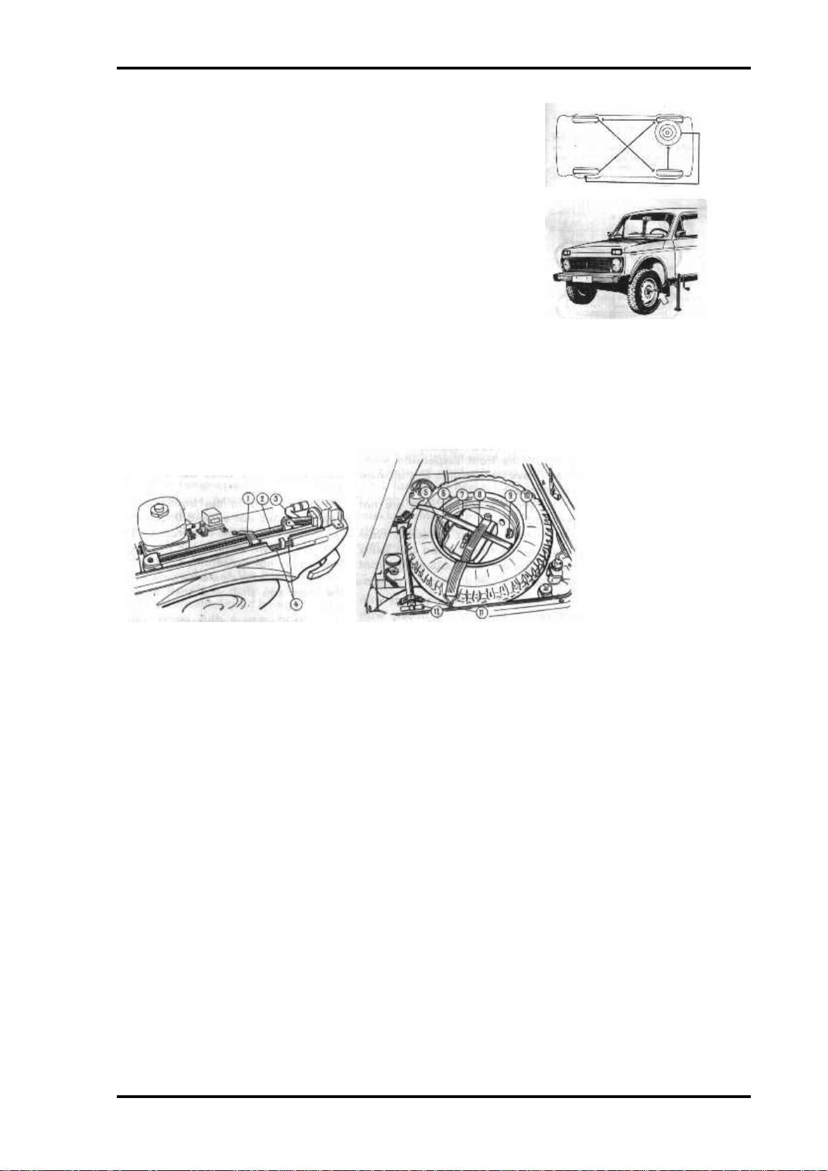
Every 10.000 Km interchange the wheels as shown in Pig. 52 to ensure uniform wear of
tyres. If abnormal vibrations in motion are detected, check wheel balance.
Page 20
Lada Niva Manual - Maintenance Page 19
Replacing the Wheels
To replace a wheel, proceed as follows:
Place the car on a level ground and apply the parking brake;
Prepare the jack, tyre pump, tools bag and spare wheel;
Use the combination wrench to slacken the wheel nuts one
Fig 52. Wheel rotation diagram
revolution;
Insert the jack arm into the socket nearest to the wheel being
replaced (Fig. 53), and rotate the jack handle until the wheel
clears the ground (the jack should not sink in the ground when
the car is being raised);
Unscrew the wheel nuts and remove the wheel. Install the
spare wheel and uniformly tighten the wheel nuts;
Fig 53. Jacking up car for
replacement of wheels.
Lower the car onto the wheels, and withdraw the jack;
Tighten the nuts to a torque of 70-90 NÆm (7-9 kg m), check tyre inflation pressure and bring
it to normal;
Stow the tools and the spare wheel under the hood, and secure them as shown in Fig. 54.
Fig 54. Stowage and
fastening of tools and
accessories. 1, 6, 8, 11-
elastic straps, 2- jack, 3starting crank, 4- tyre irons, 5inspection lamp, 7- tools bag,
9- wing nut, 10 spare wheel,
12 air pump
Front-End Alignment
Every 20,000 Km (and also after the first 2,000-3,000 Km if the car is new) as well as in case
of rapid and irregular wear of the front wheel tyres and impaired steering of the car, check the
front-end alignment. It is advisable that this operation is performed at a service station
equipped with a precision optical stand ensuring high-accuracy checking and front-end
alignment. Given below is a method, though less accurate, of checking only the wheel camber
and toe-in by the Owner himself, on condition that the following requirements are met:
Tyre inflation pressure is normal;
Radial and axial runout of the front wheel rims does not exceed 3 mm;
End play in the front wheel bearings does not exceed 0.15 mm;
Backlash in the steering worm- to-roller mesh ensures a steering wheel play not exceeding 5";
there is no clearance between the idler arm shaft and shaft bushings;
The rubber elements in the joints of the front suspension wish- bones have no ruptures and
ultimate distortions;
Shock absorber rods are not jamming; there are no excessive clearances in the steering rod ball
joints and in the ball supports of the front suspension wishbones.
Check the wheel alignment with the car in the running order, with a load of 3,200 N (320 kg)
which roughly corresponds to the weight of four persons plus 400 N (40 kg) of luggage in the
Page 21
Lada Niva Manual - Maintenance Page 20
luggage compartment. Place the car on a flat level ground and set the front wheels in the
position that corresponds to the straight-ahead motion.
To stabilise the position of the suspension units, exert pressure on them by pushing down
first the rear and then the front bumpers for 2-3 times, applying a force of about 400-500 N
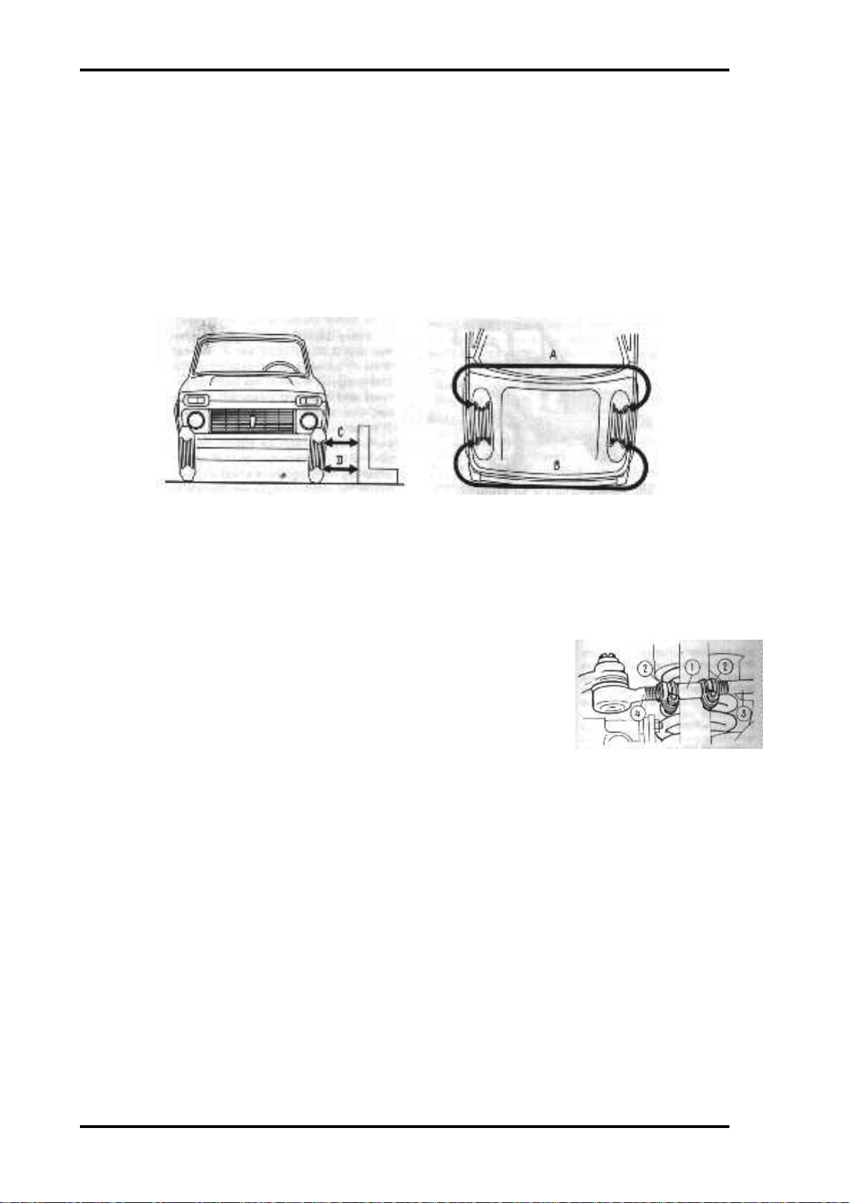
(40-50 kg). To determine wheel camber, measure distance C (Fig. 55) between the wheel rim
and the set square. Then roll the car to turn the wheels through 180", and measure distance D.
Camber is correct if distance D is 1-5 mm greater than distance C. Camber is adjusted by
changing the number of shims 20 (Fig. 51) between the upper wishbone shaft and the cross
member. Check and adjust toe-in only after checking and adjusting the wheel camber.
Fig 55. Checking front end alignment
To determine toe-in, measure distance A (Fig. 55) between the corresponding points on the
front wheel rims. Then roll the car to turn its wheels through 180" and measure distance D is
1-5 mm greater than distance C.
Camber is adjusted by changing the number of shims 20 (Fig 51) between the upper
wishbone shaft and the cross member.
Check and adjust toe-in, measure distance A (Fig 55) between the
corresponding points on the front wheel rims. Then roll the car t o
turn its’ wheels through 180 degrees and measure distance B. Toe-in is
correct, if the first dimension is 2-4 mm greater than the second one.
Toe-in is adjusted by changing the length of side steering rods 3 (Fig.
56). For this purpose loosen clamps 2 and turn adjusting sleeves 1
through the same number of revolutions in the opposite directions,
Fig 56. Adjusting length of side
steering rods. 1- sleeve, 2- clamps, 3
side steering rod, 4- steering rod end.
thus screwing the sleeves on or off and changing the length of the side
steering rods. Adjustment over, tighten clamps 2 to a torque of 19 N Æ m (1.9 kg Æ m) so that
their slots face down and their ends, after tightening, do not touch each other.
Camber and toe-in can be also checked and adjusted, though less accurately, with the car
unloaded. In this case wheel camber D-C should be from -1 to +3 mm, and toe-in A-B should
be 4~1 mm.
BRAKES
Brake Hydraulic System
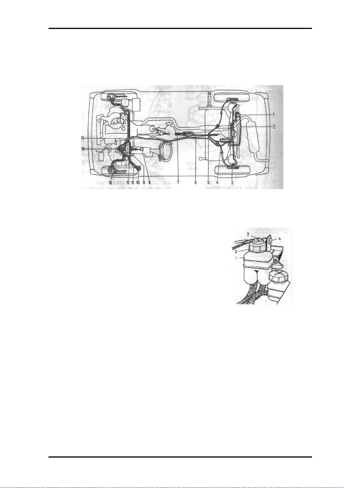
The brake system of the car is given in Pig. 57. Prior to servicing the brake system, clean each
brake of dirt, wash it with warm water and dry with compressed air.
Never use gasoline, diesel fuel, trichloroethylene or other mineral solvents for the purpose
since they attack the cups and seals of the hydraulic cylinders.
The surfaces of the brake linings should be clean, with no traces of dirt or lubricant. Soiled
linings should be cleaned with a wire brush and washed with white spirit. If the pads or linings
Page 22
Lada Niva Manual - Maintenance Page 21
are contaminated with oil, check for oil or brake fluid leakage through the seals and eliminate
the defect. During the maintenance ope- rations take care to protect the brakes from oil.
If free travel of the brake pedal exceeds 5 mm with the engine stopped, or the braking
efficiency of the wheels becomes different, per- form an all-round check of the brake system.
Fig. 57. Brake System Diagram: 1 - pressure regulator; 2 - pressure regulator torsion lever; 3 - rear brake wheel
cylinder; 4 - parking brake rear cable; 5 - rear cable equaliser; 6 - parking brake front cable; 7 - parking brake lever; 8 brake pedal; 9 - vacuum booster; 10 - brake fluid reservoir; 11 - primary brake circuit; 12 - secondary brake circuit; 13
- (rent disc brake cylinder block; 14 - brake master cylinder; (5 - T-piece
Brake Fluid Reservoir
Every 10,000 Km check the fluid level in reservoir 1 (Fig.
58), which should be as high as the lower edge of the filler
neck with cap 2 installed. Add only brake fluid Hesa or
ToML. Depress pusher 3 on the reservoir cap to check the
fluid level transmitter for proper functioning; with the ignition
switched on the warning lamp should be constantly alight. It is
recommended to replace the brake fluid after 5 years of
operation.
Fig 58. Brake fluid reservoir. 1-
Flexible brake hoses
fluid reservoir, 2- cap, 3- pusher,
4- inspection lamp socket
Every 10,000 Km, starting from 30,000 Km check condition of the brake hoses and replace
them with new ones, if minor cracks are detected on the sheathing or bulges appear on the
hose when the brake pedal is pressed.
Front Brakes
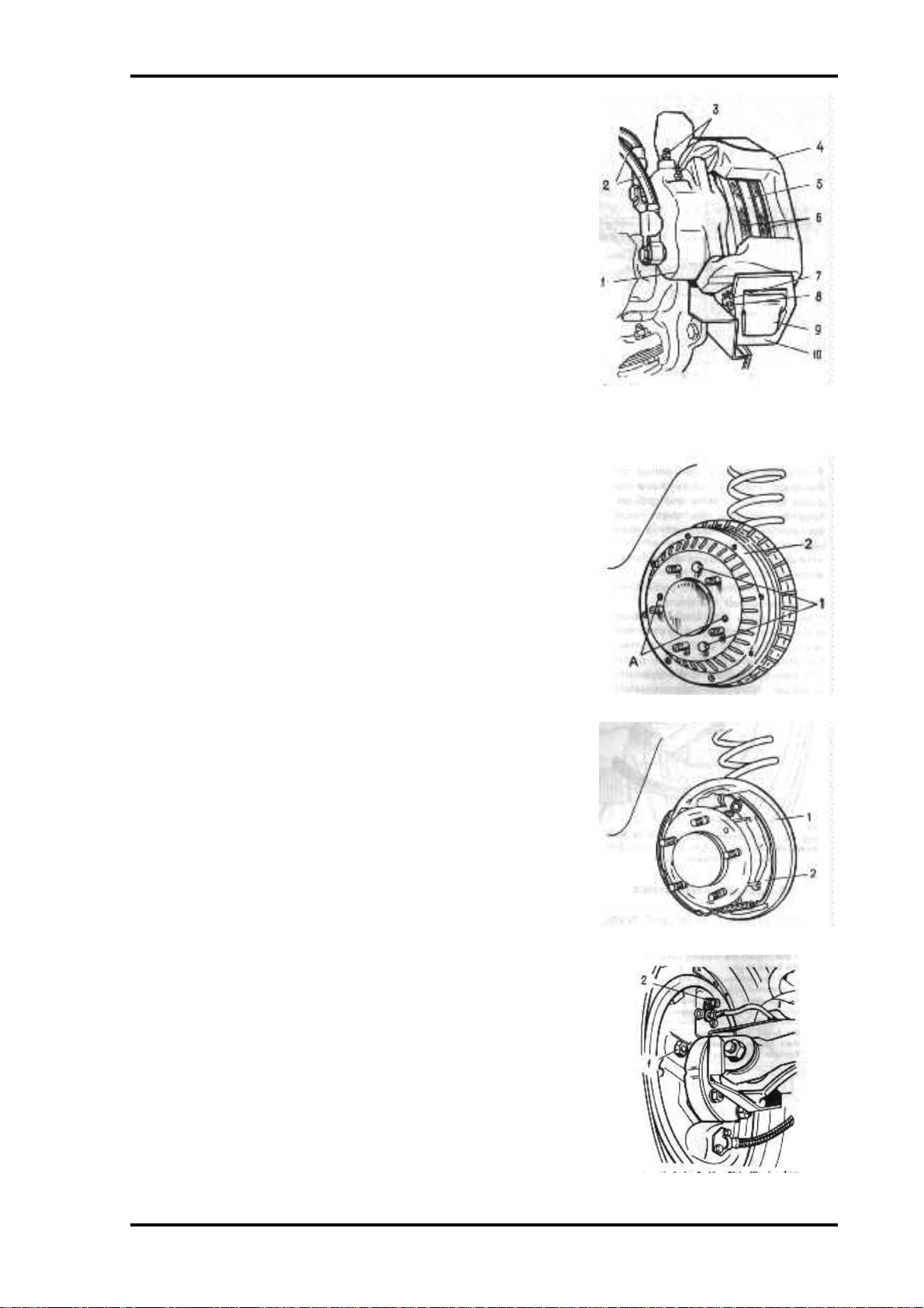
Every 10.000 Km check the condition of brake shoes 6 (Fig. 59). To remove the brake shoes
take out cotter pin 8 in the brake upper part; holding pressure lever 10, take out axle 7 and
remove the lever; shift upwards calliper 4 complete with cylinder block 1 until the lower
pressure lever is released, and remove the calliper with the cylinder block from the brake disc.
Replace the brake shoes if thickness of the friction pads is reduced to 1.5 mm. If the brake
shoes are removed for purposes other than replacement, mark them to reinstall the shoes in
their places.
Page 23

Lada Niva Manual - Maintenance Page 22
Before installation of the brake shoes, make sure that brake disc 5 is not damaged nor deeply
scored. Replace the disc if it is worn to a thickness below 9.5 mm.
To install the brake shoes push the pistons as deep into the cylinders as possible. When
doing so see that the protective rubber seals of the pistons are in their sockets and are not
damaged; replace the seals, if necessary.
When the pistons are pushed into the cylinders, the brake fluid level in the reservoir rises. To
prevent overflowing, remove the reservoir cap and timely remove the required amount of fluid
from the reservoir.
Page 24
Lada Niva Manual - Maintenance Page 23
Then install brake shoes 6, fit the calliper complete with
the cylinder block, and fix it with the pressure levers; for
this purpose press off the lower lever and shift the calliper
so that it is pressed by the lower lever; install the upper
lever, insert axle 7 and fit cotter pin 8.
Upon the installation of the brake shoes the brake system
needs no bleeding. It is sufficient to depress the brake pedal
in order to attain the normal operation of the brake system.
Bleeding of the system is necessary only after disassembly
of the cylinder block, or when air is trapped in the system;
use bleeder valves 3 to evacuate air from the system.
The adjustment required to compensate for the natural
wear of the brake friction pads is effected automatically.
Rear Brakes
Fig 59 front brake. 1- cylinder block, 2flexible hoses, 3- bleeder valves, 4- calliper,
5- brake disc, 6- brake shoes, 7- pressure
lever axle, 8- cotter pin, 9- brake shoe guide,
10 pressure lever.
Every 20.000 Km check the condition of the brake shoes
for which purpose unscrew two bolts 1 (Fig. 60), insert
them into holes A and screw them in until brake drum 2 is
moved off its place.
Check the condition of brake shoes 2 (Fig. 61) with friction
linings 1 and inspect the working surface of the brake drum.
If the brake shoes are broken or distorted which prevents
uniform shoe-to-drum contact and reduces efficiency of
braking, replace the shoes with new ones. Also replace the
brake shoes when thickness of their linings is reduced to 2
Fig 60. Rear Brake. A- holes, 1- bolts, 2brake drum
mm. Replace the shoes in pairs only.
If deep notches are formed on the drum working surface,
have the drums turned in a lathe and ground. Prior to
installing the drum, coat the mounting surface with a thin
layer of graphite grease.
Adjust the shoe-to-drum clearance as follows:
• Depress the brake pedal until the shoes contact the drum;
• Keeping the shoes pressed to the drums, turn adjusting
eccentric heads 1 (Fig. 62) until they contact the shoes;
release the brake pedal and turn the heads in the opposite
Fig 61. Rear brake with drum removed.
1- friction lining, 2- brake shoe
direction through approximately 10";
• Sharply depress the brake pedal 3-4 times and, having
released it, check the brake drum; if it is jammed, repeat
the adjustment.
Fig 62. Brake backing plate viewed from
rear axle. 1- adjusting eccentric head, 2-
rear brake bleeder valve.
Page 25
Lada Niva Manual - Maintenance Page 24
Bleeding the Brake System
An increased travel and sponginess of the brake pedal manifest the presence of air in the
brake system which impairs considerably efficiency of the brakes. Evacuate air from the
system by bleeding in succession; the brake mechanism cylinders of the R.H. rear wheel, then
of the L.H. rear wheel, of the L.H. front wheel and, finally, of the R.H. front wheel through
the upper bleeder valves. In this way the first brake circuit will be bled. To repeat the
procedure for the second brake circuit, make use of the lower bleeder valves of the front wheel
brake mechanisms. It is allowed to start the bleeding procedure from the R.H. or L.H. front
wheel.
Do not jack up the car rear to exclude influence of the pressure regulator.
To perform bleeding, proceed as follows:
1. Unscrew the reservoir cap (Pig. 58) and add some fluid up to the normal level.
2. Remove the protective caps from bleeder valves 3 (Fig. 59) and 2 (Fig. 62) and clean the
latter of dirt and dust.
3. Fit a rubber hose on the bleeder valve head (the hose is available in the set of car
accessories) and dip the hose end into a clean transparent vessel, partly filled with brake
fluid.
4. Press the brake pedal sharply 3-5 times with an interval of 2-3 s and, holding the pedal in
the pressed down position, give the bleeder valve ’/,-3/4 01 a turn out and keep pressing
down the brake pedal to force out the brake fluid together with air into the vessel. When
the brake pedal rests against the stop and escape of the brake fluid ceases, screw in the
bleeder valve. Repeat this operation until air bubbles cease to escape from the hose.
5. Keeping the brake pedal de- pressed, screw the bleeder valve all the way in and remove the
hose. Wipe the bleeder valve end dry and install the protective cap.
In the process of bleeding see that the fluid level in the reservoir is sufficient. The bleeding
over, restore the required maximum fluid level in the reservoir. The fluid discharged from the
brake system during the bleeding should not be reused.
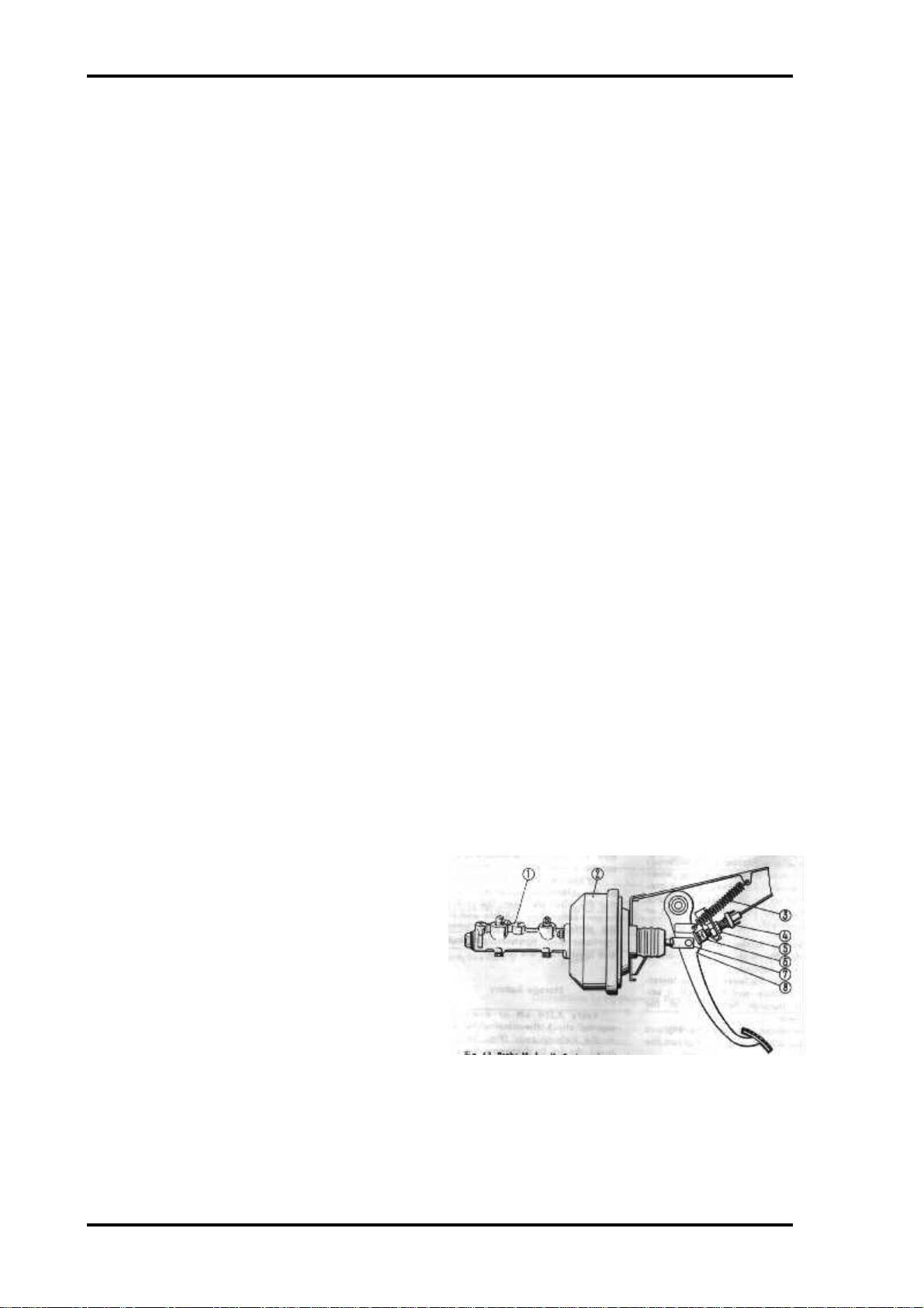
Pressure Regulator
Every 30.000 Km check the pressure regulator
for serviceability, for which purpose:
• Place the car on a lift or an inspection pit;
• Clean the regulator and its boot from dirt;
• Carefully remove the boot, wipe off the
remaining grease, and clean the torsion
lever-to-regulator piston joint;
• Ask an assistant to sharply depress the
brake pedal. With the pressure regulator
serviceable, the protruding portion of the
Fig 63. Brake hydraulic system. 1- brake master cylinder, 2- vacuum
booster, 3- pedal pull-back spring, 4- stop light switch, 5- thrust screw
nut, 6- stop light switch buffer, 7- pushrod, 8- brake pedal.
piston will move relative to the body, thus
twisting the torsion lever.
• Repeat the operation two or three times and, having made sure that the pressure regulator
is serviceable, pack 5-6 g of fresh grease P~T-1 into the regulator, and put on the boot.
• If the piston does not move relative to the body, apply to a service station.
Page 26
Lada Niva Manual - Maintenance Page 25
Adjusting the Free Travel of Brake Pedal
Every 20.000 Km (and also after the first 2,000-3,000 Km if the car is new), check and
adjust, if necessary, the brake pedal free travel. With the brake system serviceable and the
shoe-to-drum clearances of the rear wheels normal, the brake pedal free travel, with the engine
shut down, should be 3-5 mm. Adjust free travel by shifting stop- light switch 4 (Fig. 63)
together with buffer 6 after unscrewing nut 5. Adjustment over, tighten nut 5.
Brake Vacuum Booster
Every 30.000 Km check the vacuum booster for serviceability in the following manner:
depress the brake pedal 5-6 times, with the engine shut down, and holding the brake pedal
pressed, start the engine. With the vacuum booster serviceable, the brake pedal should move
further down upon starting the engine. If the pedal does not move further down, check for
tightness the hose connections to the intake manifold and to the vacuum booster, as loose
connections cause in leakage of air and sharply reduce vacuum booster efficiency. If the
trouble persists apply to a service station.
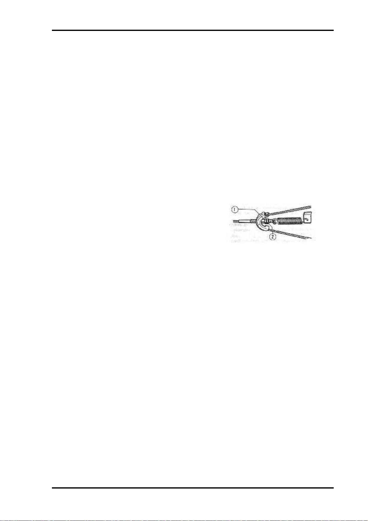
Parking Brake
Every 20,000 Km (and also after the first 2,000-3,000
Km if the car is new) adjust the parking brake.
Correct adjustment of the parking brake ensures
Fig 64. Adjusting parking brake leaver
travel. 1- adjusting nut, 2- locknut
reliable operation of the whole brake system of the car.
Perform adjustment of the parking brake after adjustment of clearances in the rear brakes and
also when the car cannot be braked on a gradient of up to 30 % with the brake lever shifted
through 4-5 teeth of the quadrant.
Parking brake lever travel is adjusted by means of the tensioning device as follows:
• Shift the lever into the lower- most position and then pull it upwards through two teeth of
the quadrant;
• Loosen locknut 2 (Fig. 64), and turning adjusting nut 1, tighten the cable;
• Tighten locknut 2 and check that the car remains braked after shifting the lever through 4-5
teeth of the quadrant.
To prevent shoe-to-drum freezing after travelling over wet roads at sharp fluctuations of
ambient temperature, do not apply the parking brake when leaving the car in a parking lot or a
non-heated garage, unless the brakes are dried by applying them smoothly while driving to the
parking area.
ELECTRICAL EQUIPMENT
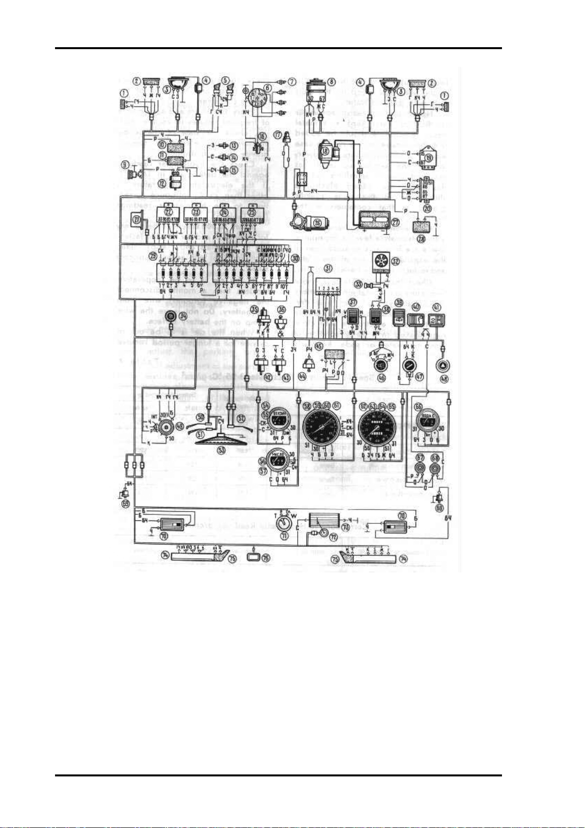
The car wiring diagram is shown in Fig. 65. Do not tamper with the car electric circuits.
Additional power consumers should be connected only by qualified electricians at a service
station. To ensure trouble-free operation of the electrical equipment check that the wires are
clean, the contacts in connections are reliable and that the protective rubber caps on the
ignition coil, ignition distributor and spark plugs are sound.
Page 27
Lada Niva Manual - Maintenance Page 26
Wiring diagram
Fig. 65. Wiring Diagram: 1- ride direction indication; 2- ride lights; 3- headlight; 4 head- light wiper motor; 5- horn; 6- ignition distributor;
7- spark plugs; 8- alternator, 9- Inspection lamp socket; 10- windshield wiper pump; (1- headlight washer pump; (I-k~Æ fluid level
transmitter; 13- coolant temperature transmitter; 14- low oil pressure warning lamp transmitter; 15- oil pressure gauge transmitter; (6-
ignition coil; 17- idling electromagnetic valve; 18- starter; 19- voltage regulator; 20- battery no-charge warning lamp relay 21- windshield
wiper relay; 22-headlighl wiper relay; 23-headlight upper beam relay; 24- headlight lower beam relay; 25- back window hooter relay; 261
windshield wiper P1- storage battery; 28- back window wiper pump; 19- additional furs block; 30-main fuse block; 31- emergency flasher
system and direction indicator (lather unit; 32-aatk) tan; 33- heater fan series resistor; 34- instrument lighting Switch; 35- stop-light switch:
1~- choke warning lamp switch; 37- external lighting switch; 38- heater fan switch; 39-blcL window wiper and washer switch; 40- back
window heater switch; 41- rear fog lamp (witch; 42- backing light switch; 43- transfer differential lock warning lamp switch; 44- parking
brake warning lamp switch; 45- parking brake warning lamp flasher unit; 46- headlight wiper twitch; 47- cigarette lighter with illumination
lamp; 41- emergency flasher system switch and warning lamp; 49- ignition switch; 50- headlight switch: 51- direction indicator switch; 52-
wind- shield wiper and washer switch; 53- horn button; 14- fuel level gauge; 55- low fuel warning lamp; 56- oil pressure gauge; 57- low
oil pressure lamp; 58- tachometer; 59- par- king brake warning lamp; 60- battery no-charge warning lamp; 61- choke warning lamp; 62-
speedometer; 63- marker light warning lamp; 64- direction indicator warning lamp; 65-headlight upper beam warning lamp; 6~-coolÆn~
temperature gauge; 67-lantlor differential lock warning lamp; 68- brake fluid low level warning lamp; 69- interior lamp door switches; 70-
interior lamps and switches; 71- fuel level and low fuel transmitter; 72-brit window wiper; 73- back window heater; 74- tail light; 75-
Wire Colour Code: P- pink; 3- green; Trl blue with black tracer; T- blue; 6-whih; 0- amber; m- yellow; C- grey; K~- brown; ~- black; K-
red; 6~- white with black tracer; mCI-yellow with black tracer; CLi-green with black tracer; 3Lt- green with black tracer; r6- blue with
white tracer; CK-grey with rod tracer; TK- blue with red tracer; 0,- violet; p’i- pink with black tracer; 61- white with blue tracer
number plate lamps: 76-fog lamp
Page 28
Lada Niva Manual - Maintenance Page 27
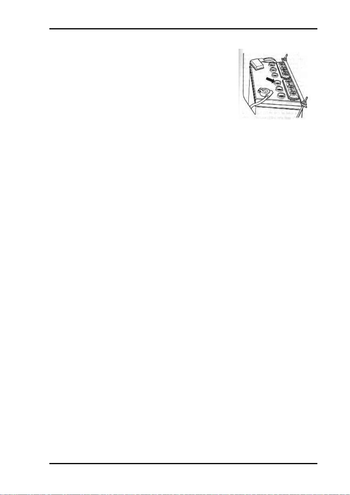
Storage Battery
Every 2,500 Km or every four months check the electrolyte
level in the battery cells (Fig. 66). The level should be between
the MIN and MAX marks on the semi-trans- parent battery
case; otherwise the level should reach the lower edge of the filler
holes. Top up the cells only with distilled water.
Never add non-distilled water or distilled water kept in a metal
vessel. Electrolyte should be added into the storage battery only
in case when it is known for sure that lowering of the electrolyte
level has occurred due to splashing out. In this case, the added
electrolyte should be of the same specific gravity as that
Fig 66. Holes for checking
electrolyte level in storage battery
cells
contained in the battery.
Operation of the battery with a low electrolyte level is impermissible since it results in
sulphation of the exposed portions of the plates and reduction of the battery capacity.
Check the electrolyte level more frequently in hot weather. The battery should always be
clean and dry, particularly its upper surface. Remove the traces of electrolyte with clean rags
soaked in a 10 % solution of ammonia water or soda. Regularly check cleanness of the vent
holes in the plugs and condition of the battery container.
Every 10,000 Km and also in case of frequent failures in engine starting, check the state of
charge by measuring the electrolyte specific gravity with a hydrometer.
Check the hydrometer readings against the data given in Table 4. (Not included yet) If the
electrolyte temperature is other than 25"C, introduce corrections to the hydrometer readings
(see Table 5).
Every 20,000 Km check the battery for cleanness and for reliable fastening of terminals and
clamps; clean them and coat with aerosol lubricant BTB-l.
If the car is to be inoperative for less than a month, disconnect the negative (ground) wire
from the battery. Do not leave the wire clamp on the battery surface. When the car is to be out
of service for a longer period remove the battery from the car, fully charge it and keep it,
whenever possible, in a dry cool room at a temperature not above O"C. The minimum storage
temperature should not be below minus 50 "C.
Never store the discharged battery since this will lead to sulphation of plates, and finally, to
a complete failure of the battery. Therefore, be sure to check the battery specific gravity every
month, charging it whenever necessary.
Alternator
Every 10.000 Km carefully dress the alternator slip rings with glass cloth, check the brushes
for wear and seating and replace them if necessary. The brushes should move easily in the
holders and should have no chippings. When the car is driven constantly on dusty and dirty
roads perform this operation more frequently.
Starter
Every 40.000 Km carefully dress the commutator, check the brushes for wear and seating
and, whenever necessary, replace them with new ones, having them bedded properly to the
commutator.
Page 29
Lada Niva Manual - Maintenance Page 28
At the same time be sure to clean and lubricate the helical splines of the starter shaft, the
bushings of both end shields and the drive pinion with engine oil, and the pinion shift ring of
the starter drive, with grease.
Voltage Regulator
Any servicing of the voltage regulator must be performed by qualified specialists only.
When installing the voltage regulator on the car or removing it from the car, see to it that the
regulator is not subject to blows which may bring it out of adjustment.
Aiming the Headlight Lower Beam
Every 20.000 Km (end also after the first 2,000-3,000 Km if the car is new) aim the
headlights. The car is equipped with head lights that have an asymmetric light distribution of
the lower beam, with a sharp boundary between the light and dark zones; such light
distribution makes it possible, with the headlight aimed properly, to reduce the dazzling effect
on the drivers of the oncoming vehicles.
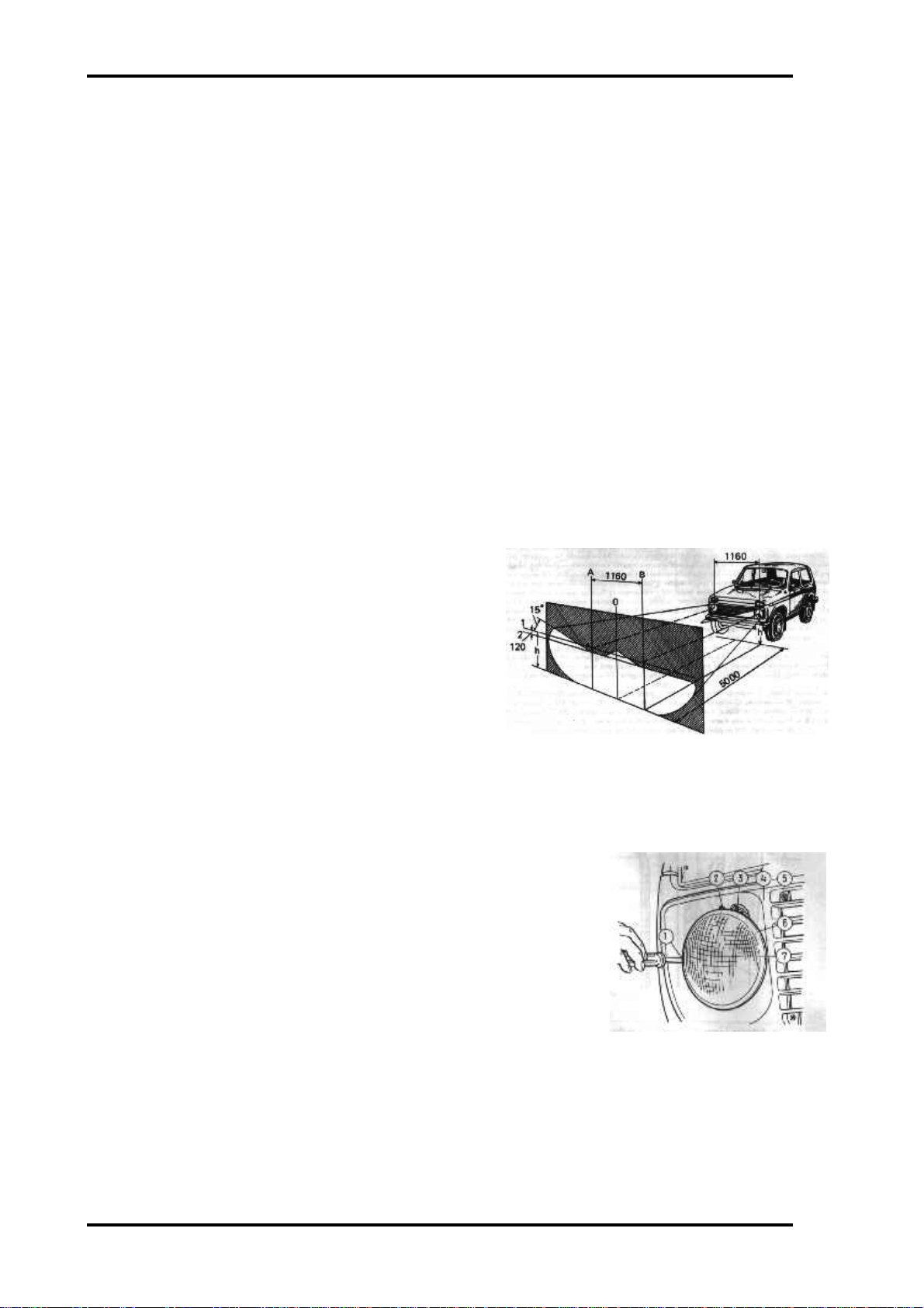
To aim the headlight lower beam proceed as follows:
1. Place the car in running order with a load of 750
n (75 kg) on the driver’s seat and with normally
inflated tyres on a level ground (Fig. 67) at a
distance of 5 m from a vertical white screen
located in a shade. A white wall of a building
may serve as a screen.
2. Rock the car sideways to stabilise the car
suspensions.
3. Draw on the screen axial line O located in the car
Fig 67. Aiming headlight lower beam
symmetry plane. Symmetrically to the axial line, draw lines A and B (a distance of 1160
mm between them should correspond to the distance between the headlight centres). Then
draw horizontal line 1 at height h (which is a distance from the headlight centre to the
ground), and line 2 which should be 120 mm below line 1.
1. Switch on the lower beam and rotating screws 1 and 2 (Fig. 68),
set the light units so that the horizontal border-line between the
light and dark zones passes along line 2 (Fig. 67), and the
inclined limiting lines come from the points of intersection of
lines A and B with line 2.
Replacing the Bulbs
To replace a bulb in the headlight, turn out screws 5 (Fig. 68)
which secure decorative grille 4 of the radiator and remove the grille;
loosen screws 3 securing the light unit rim, turn the rim counter-
Fig 68. Headlight. 1- horizontal
adjustment screw, 2- vertical adjustment
screw, 3- headlight rim screw, 4- radiator
decorative grille, 5- radiator grille screw,
6- headlight rim, 7- light unit
clockwise and remove it. Take out light unit 7 and throw off the
bulb spring clamps.
To replace the bulb in the side light or in the rear fog lamp turn out the lens fastening screws,
remove the lens, gently press on the bulb, turn it counter-clockwise, and take it out.
Page 30
Lada Niva Manual - Maintenance Page 29
A burnt-out bulb in the side direction indicator should be replaced after removing the socket
with the bulb on the engine compartment side.
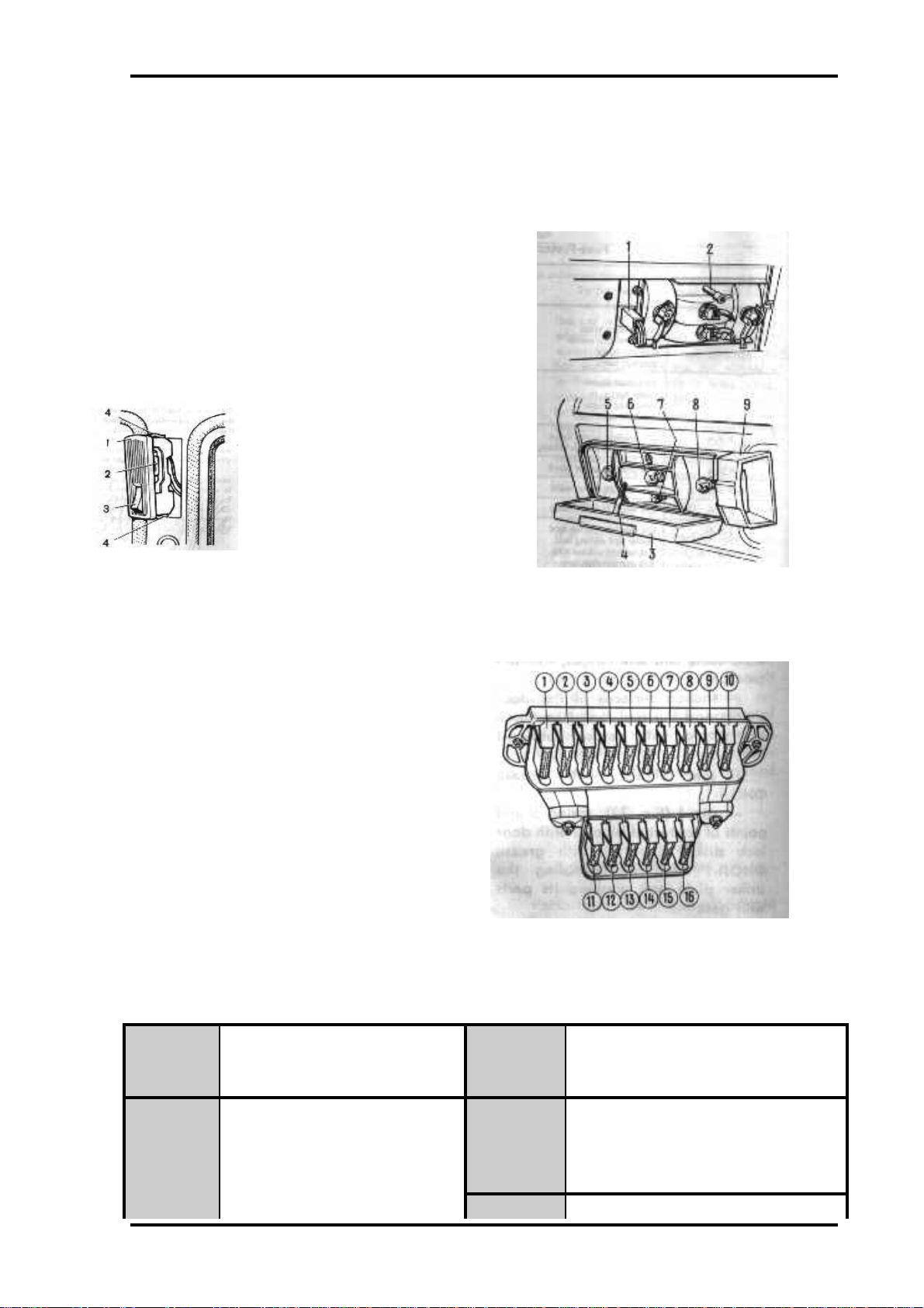
Tail lights
To replace the bulb in the tail light turn off the
upper screws which secure the luggage compartment
lining, screw off nut 2 (Fig. 69) and remove lens 3.
To replace the bulb in number plate lamp 9,
disconnect connector 1 and remove the holder with
the bulb.
To replace the bulb in the body
interior lamp. Carefully pull it out
The lamp is kept in the recess of the
centre pillar by two springs 4 (Fig.
70).
Fig 70. Interior lamp. 1lens, 2- bulb, 3- switch, 4
fastening spring.
Fuses
Fuses are installed in two blocks. The first
block contains a 16 A fuse (Fig. 71) and nine
8 A fuses. The second block contains four 8
A fuses and two 16 A fuses.
Fuses are held in the blocks by spring
contacts. The circuits protected by fuses are
listed in Table 6.
The electric circuits of ignition, engine
starting, alternator (except for the field
winding), headlight lower beam relay and
headlight upper beam relay are not protected
by fuses.
Prior to replacement of a blown- out fuse, find out and eliminate the cause of trouble.
Fuse-Protected Circuits
Fig 69. Tail light and number plate lamps. 1connector, 2- nut, 3- lens, 4-pin, 5- direction
indicator bulb, 6- reverse light bulb, 6- marker
light bulb, 8- stop light bulb, 9- number plate
lamp.
Fuse No
amperage
in Fig 71
Protected circuit Fuse No
amperage
in Fig 71
Protected circuit
1 (16 A) Horns 2 (8 A) Windshield wiper
Body interior lamps Heater fan
Inspection lamp socket Windshield washer
Cigarette lighter Headlight wiper relay
step-light bulbs 3 (8 A) LH headlight (upper beam)
Page 31

Lada Niva Manual - Maintenance Page 30
Headlight upper beam warning
lamp
Page 32

Lada Niva Manual - Maintenance Page 31
4 (8 A) RH headlight (upper beam) 10 (8 A) Voltage regulator
5 (8 A) LH headlight (lower beam) Alternator field winding
8 (8 A) RH headlight (lower beam) 11 (8 A) Rear fog lamp
7 (8 A) LH side light (marker light) 12 (8 A) Electric motors of headlight wipers
and washer
Marker light warning lamp 13(8A) Back window wiper and washer
RH tail-light (marker light) 14 (I6 A) Back window heater (power
circuit)
RH member plate lamp 15 (16 A) Reserve fuse
8 (8 A) Instrument lighting lamps 16 (8 A) Emergency flasher system switch
RH side light (marker light) end direction indicators operating
LH tail-light (marker light) in emergency mode
Cigarette lighter illumination lamp
LH number plate lamp
9 (8 A) Oil pressure gauge
Low oil pressure warning lamp
Fuel level gauge and low fuel warning lamp
Coolant temperature gauge
Direction indicators with warning lamp
Backing light lamps
Parking brake warning lamp
Brake Fluid low level warning lamp
Differential look warning lamp
Battery no-charge warning lamp
Choke warning lamp
Tachometer
Carburettor electromagnetic valve
Flasher unit of parking brake warning lamp
Direction indicator flasher unit
Back window heater (control circuit)
BODY
Care of Body
To preserve the attractive appearance of the car give constant attention to the car body
surfaces. To prevent scratches on the body do not remove dirt and dust from the car with dry
rags. Wash the car when mud is still wet, using a weak water spray end a soft sponge. In hot
weather wash the car outdoors in the shade. If this is impossible, immediately wipe the
washed surfaces dry, since drops of water that dry under the sun rays leave stains on the
body painted surface. At sub- zero ambient temperatures, having washed the car in a warm
room, wipe the body dry before a trip because frozen drops of water may cause cracks on the
body paint coating. It is not recommended to use soda and alkaline solutions, as they may
tarnish the paint coating.
When using a hose for washing, see that water does not get on the electric units in the engine
compartment.
Page 33

Lada Niva Manual - Maintenance Page 32
Minor chipping of paint on the car body should be timely sanded and coated with the paint
contained in the tin furnished with the car.
In case corrosion of the car body parts is detected (corrosion traces, local paint blisters, etc.),
take necessary measures to eliminate corrosion and prevent its further spreading.
To facilitate examination of boxed spaces of the front fenders, the shields with weatherstrips
are made detachable.
To retain lustre of the body paint- work, particularly of the cars kept outdoors, regularly
polish the paint coating with the use of polishing pastes or wax compounds.
To ensure prolonged shining of the body surfaces, do not leave the car under the sun rays for
a long period of time; prevent acids, soda solutions, brake fluid and gasoline from getting on
the painted surfaces.
To prevent stains on the paint coating under the fuel tank access flap caused by spilled
gasoline, wipe the surface with clean dry rags before and after the fuel servicing.
In the course of operation the car underbody coating is attacked by gravel, sand and salt. As a
result, the anticorrosion compound and primer come off, and the exposed metal gets corroded.
Therefore regularly check the condition of the car underbody coating and timely recondition
the damaged areas.
Clean the chrome-plated parts with soft rags and petrolatum. Wipe the plastic parts with
wet rags. It is not recommended to use gasoline or solvents; otherwise, the plastic parts will be
tarnished.
Use soft linen rags or chamois leather to clean the glasses. To clean heavily soiled glasses first
wash them with water solution of HMMCC-Æ1 liquid or Glass Autocleanser-2 (30 cm3 per
litre of water).
Never use gasoline or solvents to clean the body interior upholstery made of artificial leather.
Use neutral soap with water for the purpose, then wipe the surfaces dry with soft rags or
chamois leather. Simultaneously thoroughly wipe with wet rags the rubber weatherstrips and
the door parts in contact with them.
Periodically, depending on the specific conditions of the operation (very cold climate, dusty
roads, atmospheric effects during long parking periods), lubricate the following parts and
units: - door lock keyholes;
(a) in hot weather with graphite powder;
(b) in cold weather, particularly after washing, with aerosol lubricant BTB-1: as a
preliminary, dry the lock keyholes with compressed air;
Door hinges, hood lock re- lease cable and seat hinges, with engine
oil; friction surfaces of the door checks and the fuel tank flap hinge
and spring, with aerosol lubricant BTB-1; - seat slides, with grease
cDMOn-l ; pin 4 (Fig. 72), spring 5 and points of contact of block
2 with door lock striker plate 1, with grease cDMOn-1 after
disassembling the striker plate and washing its parts with gasoline.
The car body doors should open and close easily. If the door
closes with difficulty or loosely, adjust the position of the door
Fig 72. Door lock striker plate. 1striker plate, 2- block, 3, bolt, 4- pin,
5- spring, 6 bushing.
lock striker plate. Prior to beginning the adjustment, outline the position of striker plate 1 on
the car body pillar with a pencil. If the door is hard to close, loosen bolts 3, move the striker
plate outward and tighten the bolts. If the door closes loosely, move the striker plate inward.
If the door sags in closing, raise the striker plate, and on the contrary, lower it, if the door
Page 34

Lada Niva Manual - Maintenance Page 33
rises. If, for some reason or other, the door lock has been disassembled, wash it to remove old
grease and, prior to assembly, lubricate it with grease. It is not re- commended to use other
grades of grease because at low temperatures the lock may fail to operate, or the door may get
spontaneously opened in motion.
Windshield and Headlight Washers
Periodically clean the windshield and headlight washer nozzles end also check the direction of
the washing spray which should be aimed at the upper zone of the sector swept by the wiper
blade. Adjust the direction of the spray by turning the nozzle with the fastening screw
loosened. Adjustment over, tighten the screw. In hot weather the washer reservoir may be
filled with clean water, while in cold weather, at an ambient temperature down to minus 25"C,
only with a mixture of the HMMCC-4 fluid or Glass Autocleanser-2 (25-33 %) and water.
Windshield and Headlight Wipers
In winter, prior to switching on the wipers, make sure that the wiper blades are not frozen to
the glass. Failure to observe this recommendation may lead not only to breakage of the blades,
but also to failure of their electric drives.
Fastening of Units and Mechanisms to Car Body
Every 20,000 Km (and also after the first 2,000-3,000 Km if the car is new) check and, if
necessary, tighten the fastenings of various units and mechanisms to the car body.
MAINTENINCE IN LONG-TERM STORIGE
The best method is to store the car in a dry, dark and well-ventilated room at a temperature
of not below 5 "C and a relative humidity of 50- 70 %. In this case the storage battery and the
car radio may be left in the car.
When the car is stored in a cold room, remove the storage battery and the radio and keep
them separately; drain fluid from the washer tank. If the cooling system is filled with water,
drain it.
When storing the car in a room lighted by sun rays protect the car body and tyres with a
cover made of moisture-permeable material. The employment of covers made of water- proof
materials (canvas, plastic film, and the like) having no vent holes within the zone of the
windshield and back window leads to condensation of moisture on the body surface;
prolonged action of moisture on the body paintwork may ruin it.
If the car is kept outdoors under a cover, the cover should not contact the body painted
surfaces, otherwise the paint coating may be damaged (blisters, peeling, etc.). To provide
normal ventilation, place soft spacers, at least 20 mm high, between the cover and the body.
When preparing the car for long- term storage, proceed as follows:
1. Wash the car and wipe its body dry. Remove traces of corrosion. Touch up damaged
painted surfaces. Apply a wax compound to the body and polish the latter.
2. Start the engine and warm it up. Turn out the spark plugs and pour 25-30 g of engine oil
heated to 70-80"C into each cylinder. To spread the oil uniformly on the entire surface of
the cylinders, give the crankshaft 10-15 revolutions with a starting crank, and screw in the
spark plugs.
Page 35

Lada Niva Manual - Maintenance Page 34
3. Use an oiled tape (paper or fabric) to seal the following holes: - in the air intake pipe of
the air cleaner housing; in the muffler tail pipe; in the fuel tank vent pipe.
4. Reduce the tension of the alternator drive belt.
5. Grease-gun the propeller shaft splined joints and crosses.
6. To protect the engine from dust cover if with a piece of canvas, film or oiled paper.
7. Clean all the electric wires of dirt arid wipe them dry.
8. Apply slushing compound HT-208 to all the chrome-plated parts of the body. As an
equivalent use gun grease or petrolatum (the latter must be renewed every four months).
Do not use cup grease for this purpose since it has to be renewed every two months.
9. Place the car on four supports so that the wheels are clear of the ground. Position the
supports under the brackets located near the sockets for the jack arm. Deflate the tyres to
0.05 MPa (0.5 kgf/cm2).
10. Check the driver’s tools for missing items, coat them with a slushing compound and wrap
in oiled paper.
11. Put the cover on the car.
Maintenance of the car in storage (once every two months) consists in the
following:
• Take off the cover and examine the car. Clean and touch up the corroded areas on the
painted surface; clean off any corrosion from the chrome-plated surfaces and coat them
with nitrocellulose varnish.
• Screw out the spark plugs, shift into the 1st gear, give the crank- shaft 10-15 revolutions
with the starting crank and screw the spark plugs back in place.
• Give the steering wheel 1-1.5 revolutions either direction. Operate the brake and clutch
pedals, accelerator pedal, parking brake handle and choke control knob 3-5 times.
Page 36

Page 37

The design of the clutch is shown on fig. 3-1. The clutch release fork 11 (fig. 3-1) can be of two types: with a leaf or wire spring.
Chapter 3. Power train
Clutch
57
Fig. 3-1. Clutch assembly:
1 - bleeder; 2 - central diaphragm spring; 3 - diaphragm spring rivet; 4 - pressure plate; 5 - clutch disc; 6 - flywheel; 7 - clutch bellhousing; 8 - bellhousing-to-flywheel bolt;
9 - gearbox input shaft; 10 - clutch release bearing assembly; 11 - clutch release fork; 12 - release fork ball socket; 13 - clutch release bearing; 14 - pressure plate thrust
flange; 15 - clutch release fork boot; 16 - clutch release fork spring; 17 - pressure plate fulcrum ring; 18 - clutch cover; 19 - clutch release fork pushrod; 20 - adjusting nut;
21 - locknut; 22 - protective cap; 23 - clutch release cylinder (slave cylinder); 24 - fork return spring; 25 - return spring bracket
Page 38

Fault diagnosis
Diagnosis Remedy
Incomplete clutch release (clutch spin)
1. Excessive gaps in clutch release drive
2. Buckling of clutch disc (camming action more than 0.5 mm)
3. Roughness on clutch disc friction linings
4. Jammed rivets or broken clutch disc friction linings
5. Jammed clutch disc hub on primary shaft splines
6. Broken thrust flange-to-clutch cover connecting plates
7. Air in clutch hydraulic drive system
8. Liquid leak from hydraulic drive system through connections or damaged pipelines
9. Leaking master cylinder or clutch release cylinder
10. Plugged opening in reservoir cover, causing underpressure and vacuum leak in cylinder through sealings
11. Vacuum leak due to fouling or wear of front sealing ring in master
cylinder
12. Skew or buckling of pressure plate
Incomplete clutch engagement (clutch slips)
1. No gaps in clutch release drive
2. Badly worn or burnt clutch disc friction linings
3. Excessive oil on clutch disc friction linings, surfaces of flywheel and
pressure plate
4. Plugged compensation port in master cylinder
5. Damaged or jammed clutch release drive
Clutch judder
1. Jammed clutch disc hub on primary shaft splines
2. Excessive oil on clutch disc friction linings, surfaces of flywheel and
pressure plate
3. Jammed clutch release drive mechanism
4. Badly worn clutch disc friction linings
5. Loose rivets on clutch disc friction linings
6. Damaged surface or buckling of pressure plate
Excessive noise at clutch release
1. Worn, damaged or dry clutch release bearing
2. Worn front bearing on gearbox primary shaft
Excessive noise at clutch engagement
1. Broken or weak damper spring
2. Broken, weak or detached clutch release fork return spring
3. Broken pressure plate-to-clutch cover connecting plates
Clutch release drive adjustment
58
1. Adjust clutch release drive
2. Straighten or replace disc
3. Renew linings or clutch disc assembly
4. Renew linings, check disc runout
5. Clean splines, apply grease ãëñ-15 or îËÓÎ-1, îËÓÎ-2. In case of badly
worn splines causing seizure, renew input shaft or clutch disc
6. Renew clutch cover/pressure plate assembly
7. Bleed system
8. Tighten connections, renew damaged components, bleed system
9. Renew sealing rings, bleed system
10. Clean opening in tank cover, bleed system
11. Clean sealing ring, replace in case of wear
12. Renew clutch cover/pressure plate assembly
1. Adjust clutch release drive
2. Renew linings or clutch disc assembly
3. Clean oily surfaces with white-spirit, remedy the situation
4. Wash cylinder and clean port
5. Rectify malfunctions causing jamming
1. Clean splines, apply grease ãëñ-15 or îËÓÎ-1, îËÓÎ-2. In case of badly
worn splines causing seizure, renew input shaft or clutch disc
2. Clean oily surfaces with white-spirit, remedy the situation
3. Replace damaged parts, rectify malfunctions causing jamming
4. Renew linings, check for damages on disc surfaces
5. Renew damaged rivets and linings, if necessary
6. Renew clutch cover/pressure plate assembly
1. Renew clutch disc assembly
2. Renew spring or secure
3. Renew clutch cover/pressure plate assembly
1. Renew bearing
2. Renew bearing
The following adjustments are carried out in the clutch
release drive:
- the 0.1-0.5 mm gap between the pushrod and the piston of the
master cylinder (see fig. 3-2) is set. This gap, necessary for complete clutch release, is adjusted by the clutch pedal limiter bolt 5. The
clearance is determined by the pedal free travel equal to 0.4-2 mm;
- the free travel of the clutch release fork pushrod, equal to 4-
5 mm, is adjusted by bolt 5 (fig. 3-3) and fixed by locknut 6. The dis-
tance of the pushrod free travel is controlled by a special pattern.
After carrying out the above described adjustments the clutch
pedal free travel should make 25-35 mm.
Page 39

Bleeding the clutch hydraulic system
Air in the clutch hydraulic system is indicated by incomplete
clutch release, and also by "sponginess" and "failure" of clutch
pedal.
To expel air from the hydraulic drive:
- clean the tank and the bleeder from dust and dirt;
- check the liquid level in the hydraulic system tank and top
up if necessary;
- put a hose on bleeder 9 (see fig. 3-3) of the slave cylinder
and place its lower end into a container with hydrodrive liquid (3050 gr);
- undo bleeder 9 by 1/2-3/4 turn, several times rapidly
depress and smoothly release the pedal until there will be no air
bubbles coming out from the hose;
- depress the pedal and fully tighten the bleeder. Remove the
hose and refit the bleeder cap.
If, despite a continuos bleeding, there are still air bubbles in
the hose, check the tightness of connections, find out if there are
cracks on tubes or leaks in places of connections. Air inleak is
possible through damaged sealing rings of the master or slave
cylinders.
During bleeding:
- the liquid level in the reservoir should be higher than the
opening of the tube connecting the reservoir with the master
cylinder;
- the end of the bleeding hose should be always dipped in liquid;
- after bleeding, top-up liquid in the reservoir to the lower
edge of the filler neck.
59
Fig. 3-2. Clutch pedal and master cylinder:
1 - pedal cluster mounting bracket; 2 - clip; 3 - clutch pedal servo spring; 4 - clutch pedal return spring; 5 - clutch pedal limiter bolt; 6 - clutch pedal; 7 - pushrod;
8 - protective cap; 9 - circlip; 10 - pushrod piston; 11 - sealing ring; 12 - master cylinder piston; 13 - inlet port; 14 - sealing ring (ring valve); 15 - piston bypass orifice;
16 - cylinder cavity; 17 - piston return spring; 18 - gasket; 19 - plug; 20 - master cylinder body; 21 - bypass (compensation) port; 22 - gasket; 23 - union; 24 - washer
Page 40

Clutch assembly - removal and refitting
Removal. First remove the gearbox (see "Gearbox"). Undo the
bolts and remove the clutch cover in assembly with the pressure
plate. Do not lift this unit by holding the pressure plate thrust flange.
Refitting is a reversal of removal, providing the following:
- inspect the bearing on the crankshaft end face, if necessary
replace the bearing;
- inspect the splines on the clutch disc hub and the gearbox
input shaft, clean the splines and grease with a thin layer of
greasing ãëñ-15 or îàéã-1, îàéã-2;
- refit the clutch disc with the hub protruding part facing the gearbox and centralise the plate against the bearing using tool A.70081,
simulating the gearbox input shaft splined end (fig. 3-4).
60
Fig. 3-3. Slave cylinder and clutch release fork:
1 - release bearing; 2 - ball pivot; 3 - clutch release fork; 4 - pushrod; 5 - adjusting bolt; 6 - locknut; 7 - return spring; 8 - plug; 9 - bleeder; 10 - cylinder body; 11 - sealing
ring; 12 - protective cap; 13 - piston; 14 - sealing; 15 - sleeve; 16 - spring; 17 - spring disc; 18 -lock ring
Page 41

Clutch inspection
The inspection of the clutch is carried out on a bench, which
simulates the engine flywheel and has a metal intermediate ring
4 (fig. 3-5) with thickness of 8.2 mm simulating the clutch disc.
Having fixed the clutch cover, make four release strokes equal to
8-9 mm. The release stroke of 8 mm should correspond to the
travel of the pressure plate within 1.6-1.7 mm (permitted minimum - 1.4 mm).
The distance from the rig base to the working surface of the
thrust flange friction washer should be 40-43 mm. During engine
operation due to wear of the clutch disc surfaces this size
increases. If it will reach 48 mm or the travel of the pressure plate
will be less than 1.4 mm, renew the clutch cover in assembly with
the pressure plate.
The clutch disc friction linings should be replaced at any signs
of cracks, reduction of distance between the rivet and the working surface up to 0.2 mm, and also at one-side scuffings. To
repair the clutch disc and replace the friction linings use tool
67.7822.9529 (fig. 3-6).
Flared rivets should have no breaks. The runout of the friction
lining working surface should not exceed 0.5 mm. If this value is
exceeded, straighten the disc (fig. 3-7) or replace with a new one.
Also replace the clutch disc assembly in case of cracks on the
clutch disc or the damper springs.
Master and slave cylinders - removal and refitting
First, drain working liquid. To do this, attach one end of the
hose to bleeder 9 (see fig. 3-3) on the slave cylinder, and the
other end place in a clean reservoir; unscrew bleeder 9 by 1/2-3/4
turn and depress the pedal several times until all liquid will be
removed from the hydrosystem, then disconnect the tubes
between the master and the slave cylinders, disconnect the
return spring 7, remove the pin from the pushrod end, and the
slave cylinder, having prior undone two fastening bolts.
To remove the master cylinder undo two nuts, with which it is
pinned to the pedal bracket, and disconnect the flexible hose
from the reservoir.
To refit the master and slave cylinders the above described
operations are executed in reverse order.
After filling with working liquid, bleed the system.
61
Fig. 3-4. Centering the clutch disc with tool A.70081:
1 - flywheel; 2 - clutch assembly; 3 - tool A.70081
Fig. 3-5. Clutch check:
1 - pressure plate thrust flange; 2 - central diaphragm spring; 3 - clutch disc;
4 - ring
Fig. 3-6.Replacing the clutch disc friction linings:
1 - tool 67.7851.9500; 2 - clutch disc; 3 - fixture 67.7822.9517
Page 42

62
Fig. 3-8. Master cylinder components:
1 - body; 2 - sealing; 3 - plug; 4 - gasket; 5 - union; 6 - retaining washer;7 - cap;
8 - circlip; 9 - pushrod piston; 10 - sealing ring; 11 - master cylinder piston;
12 - spring
Fig. 3-7. Straightening the clutch disc
Fig. 3-9. Slave cylinder components:
1 - body; 2 - bleeder; 3 - cap; 4 - pushrod; 5 - sealing ring; 6 - piston; 7 - sealing ring; 8 - sleeve; 9 - spring; 10 - disc; 11 - lock ring
Page 43

Master and slave cylinders dismantling, inspection, repair and reassembly
Master cylinder. Turn out plug 3 (fig. 3-8), remove protective
rubber cap 7 and circlip 8. This will allow to withdraw from the
cylinder body piston 9, sealing ring 10, floating piston 11 with
sealing ring and piston return spring 12.
Cylinder mirror and the outer surface of the piston should
have no damages or marks. The inner diameter of the cylinder
should be within the limits of 19.035-19.075 mm.
Inspect the piston return spring and replace if it has become
weak.
Renew sealing rings. Inspect the protective cap on the rear
end of the cylinder and renew in case of damage. Before reassembly, accurately clean and wash all parts in brake liquid. Do
not let mineral oil, petrol, kerosine or diesel fuel to get in contact
with the parts as this may cause swelling of the rubber sealings.
After inspection, reassemble all parts of the master cylinder
in reverse order; grease all components with brake liquid or
preservation liquid çÉ-213.
Slave cylinder. Turn out plug, take off protective rubber cap
3 (fig. 3-9) together with pushrod 4, take out piston and dismantle it, previously having removed lock ring 11.
After dismantle, accurately wash and check all parts, as it is
specified for the master cylinder. Do not refit a damaged
pushrod.
After inspection, begin to reassemble in reverse order,
grease all parts with brake liquid.
Clutch master cylinder - bench-check
Checking the leak-proofness of the rear sealing ring.
Place the master cylinder on the test-bench (see fig. 3-10), and
ensure good sealing between the cylinder flange and the surface
of the test-bench. Connect reservoir 2 with hydraulic liquid to the
cylinder. Open the compressed air vent, with the adjusting screw
6 being open, and then slowly close the adjusting screw until all
air will be expelled from reservoir 2.
Control air pressure by the pressure gauge, it should be within 0.05-0.08 MPA (0.5-0.8 kgf/cm2). If pressure is less, replace
the rear sealing ring.
Checking the leak-proofness of the front sealing ring.
Place the master cylinder on the test-bench and connect it to the
reservoir with hydro drive liquid, and with manometers (fig. 3-11).
Close manometer vent 3 and, by moving the master cylinder
pushrod, provide constant pressure of 0.2 MPA (2 kgf/cm2).
With a fixed pushrod and no liquid leaks pressure should
remain constant during 2 minutes.
Close pressure gauge vent 4 and open pressure gauge vent
3. By moving the pushrod provide constant pressure of 10 MPA
(100 kgf/cm2).
With a fixed pushrod and no liquid leaks pressure should
remain constant for no less than 2 minutes. Otherwise, replace
the front sealing ring.
63
Fig. 3-10. Checking the leak-proofness of the rear sealing ring:
1 - master cylinder; 2 - reservoir; 3 - adapter with sealing; 4 - manometer;
5 - T-connector; 6 - adjusting screw; A - air from compressor; B - air outcome
Fig. 3-11. Checking the leak-proofness of the front sealing ring:
1 - bleeding screw; 2 - vent; 3 - manometer with 0.2 MPa (2 kgf/cm
2
) scale;
4 - manometer with 0.005 MPa (0.05 kgf/cm2) scale; 5 - reservoir;
6 - pushrod; 7 - master cylinder
Page 44

Gearbox
The design of the gearbox is shown on fig. 3-12, 3-26, 3-34.
Fault diagnosis
Diagnosis Remedy
Noise in gearbox
1. Noise in bearings
2. Worn teeth on gears and synchro units
3. Low oil level in gearbox
4. Axial shaft movement
Difficulty in engaging gears
1. Incomplete clutch release
2. Jammed gearshift lever balljoint
3. Deformed gearshift lever
4. Hard movement of fork rods
(burrs, dirty rod sockets, detent
seizure)
5. Hard movement of sleeve on
hub when splines get dirty
6. Deformed gearshift forks
Jumps out of gear or incomplete clutch engagement
1. Worn rod balls and sockets,
weak detent spring
2. Worn synchro unit baulk rings
3. Broken synchro unit spring
4. Worn teeth on synchro unit
sleeve or synchro unit crown
5. Crushed hub short teeth
Oil leak
1. Worn oil seals on input and
output shafts
2. Loose fitting of gearbox covers, damaged sealings
3. Loose fitting of clutch housing
to transmission casing
Removal and refitting
Removal. Place the vehicle over an inspection pit or on a lift,
put blocks under front wheels and raise the rear axle from one or
two sides. Let off the handbrake and place the gearshift lever in
neutral. Disconnect the wires from the battery.
Take out the front floor mat and the gaiters from the transferand gearbox levers. Remove the aperture covers and sealings.
Unscrew the handles from the transfer box levers.
Push downward lever rod 27 (see fig. 3-12) and with the help
of a screwdriver or any other pointed tool take out the retaining
sleeve 31 from the groove on the lever rod; remove the rod.
Disconnect the brackets that are fixing pipes and mufflers in
the rear part of the vehicle, and then the muffler pipe from the
front exhaust pipe. Disconnect the exhaust pipe clip and remove
the pipe downward.
Undo the lower bolts of the clutch bellhousing cover plate.
Disconnect the "ground" wires from the clutch bellhousing and
the wires from the tail light switch.
Unhook the return spring 1 (fig. 3-13) from the clutch release
fork 5 and take pin 4 out from pushrod 6. Disconnect the slave
cylinder 8 from the clutch bellhousing. Thus, cylinder 8 connected to the master cylinder hose, remains on the vehicle, what
excludes loosing brake liquid and necessity of the subsequent
bleeding of the clutch release hydraulic drive.
Put clip 2 (A.70025) on the flexible coupling 3 (fig. 3-14) and
tighten. This will help in subsequent removal and refitting of the
flexible coupling. Undo nuts 1 and, by turning the layshaft,
remove the bolts that are fastening the flexible coupling 3 to the
flange of the gearbox output shaft.
Disconnect the speedometer cable from the speedometer
drive unit on the transfer box.
Disconnect the shaft flanges of the front and rear axles drive
from the flanges of the transfer box shafts. Lower and move aside
the axle drive shafts.
Undo the bolts that are fastening the transfer box brackets to
the car body and remove it together with the propeller shaft.
Using a socket spanner 02.7812.9500 undo the bolts fastening the starter motor to the clutch bellhousing and release it.
Undo the clutch bellhousing cover plate bolts.
Disconnect the engine rear mounting from the crossmember
4 (fig. 3-14), and then remove the crossmember while supporting
the gearbox from below.
Place a jack or other suitable support under the transmission casing. Using a socket spanner A.55035 undo the fastening bolts and
remove the gearbox together with the clutch bellhousing by moving it
to the rear part of the vehicle so that to take out the gearbox input
shaft from the front bearing and from the clutch disc hub.
ATTENTION. So that not to deform the clutch straps, do
not rest the end of the input shaft on the clutch diaphragm
spring flange when removing or refitting the gearbox.
Refitting the gearbox is a reversal of removal. Before refit-
ting, apply a thin layer of greasing глс-15 (ганйг-24) on the
spline end of the input shaft and centralize the clutch disc using
tool A.70081 (see fig. 3-4).
64
1. Renew damaged bearings
2. Replace worn parts
3. Top up oil. Rectify cause of oil
leak
4. Renew bearings or securing
components
1. Replace oil seals
2. Tighten nuts (see torque in
Appendix) or renew seals
3. Tighten nuts
1. See. subsec."Clutch"
2. Clean ball contact surfaces
3. Rectify deformation or renew
lever
4. Repair or renew worn components
5. Clean components
6. Straighten forks or renew
1. Renew damaged components
2. Renew baulk ring
3. Renew spring
4. Renew sleeve or gear
5. Renew synchro hub
Page 45

65
Fig. 3-12. Gearbox:
1 - input shaft; 2 - front cover with guide sleeve; 3 - input shaft oil seal; 4 - spring washer; 5 - bearing set collar; 6 - gearbox housing; 7 - breather; 8 - output shaft needle
bearing; 9 - synchro spring thrust washer; 10 - 4th speed synchro unit crown; 11 - 3rd/4th synchro unit sleeve; 12 - 3rd/4th synchro unit hub; 13 - circlip; 14 - baulk ring;
15 - synchro unit spring; 16 - 3rd speed synchro unit crown and gear; 17 - 2nd speed synchro unit crown and gear; 18 - output shaft; 19 - 1st speed synchro unit crown
and gear; 20 - 1st gear bush; 21 - output shaft idler bearing; 22 - idler bearing lock plate; 23 - flange; 24 - bellows; 25 - spring; 26 - gear shift lever; 27 - lever rod;
28 - damper rubber pad; 29 -grommet; 30 - distance washer; 31 - retaining sleeve; 32 - collar; 33 - cap washer; 34 - ball socket; 35 - gearshift lever housing; 36 - guide
plate; 37 - driveline coupling flange; 38 - nut; 39 - centering ring oil seal; 40 - centering ring; 41 - circlip; 42 - output shaft rear bearing oil seal; 43 - output shaft rear bearing; 44 - distance washer; 45 - oil deflector washer; 46 - 5th/reverse gear unit; 47 - 5th synchro unit hub; 48 - reverse idler gear; 49 - intermediate shaft rear bearing;
50 - intermediate shaft 1st speed gear; 51 - 1st/2nd synchro sleeve; 52 - intermediate shaft 2nd speed gear; 53 - intermediate shaft 3rd speed gear; 54 - filler and check
orifice plug; 55 - intermediate shaft; 56 - intermediate shaft constant mesh gear; 57 - intermediate shaft front bearing; 58 - intermediate shaft bearing clamping washer;
59 - clamping washer bolt; 60 - input shaft constant mesh gear; 61 - input shaft rear bearing; 62 - circlip
Page 46

Dismantling and reassembly
Dismantling. Wash the gearbox and place it on a bench.
Drain oil and remove the bottom cover with the lining.
Remove the clutch release fork, and the coupling in assem-
bly with the bearing and the spring from the guide sleeve in the
gearbox front cover.
Remove the clutch bellhousing with the lining and the front
cover together with the oil seal and spring washer (see fig. 3-15).
Turn out the rear light switch, take care not to deform the
housing.
66
Fig. 3-13. Clutch release drive:
1 - fork return spring; 2 - locknut; 3 - adjusting nut; 4 - cotter pin; 5 - clutch
release fork; 6 - pushrod; 7 - slave cylinder fastening bolt; 8 - slave cylinder
Fig. 3-14. Flexible coupling between the propeller shaft and the gearbox:
1 - propeller shaft flange-to-flexible coupling fastening nuts; 2 - clamp A.70025;
3 - flexible coupling; 4 - rear engine mounting crossmember
Fig. 3-15. Clutch bellhousing, view from inside.
The black arrows point to the gearbox-to-clutch bellhousing fastening nuts; the
white arrow points to the opening in the front cover for oil outflow from the transmission casing to avoid clutch disc contamination.
Fig. 3-17. Removing the coupling centering ring from the propeller shaft
Fig. 3-16. Removing the circlip
Page 47

Turn out the 3rd/4th gearshift fork fastening bolt. Install lock
41.7816. 4068 on the input shaft or simultaneously engage both
gears. This will prevent the turning of the input, output and intermediate shafts and will allow to do the subsequent operations on
dismantling.
ATTENTION. Since 1997, on the rear end of the gearbox
output shaft the design of the following parts was changed:
- instead of a metal centering ring 26 (see fig. 3-31) and
circlip 1, a rubber centering bush is installed;
- instead of sealing 25 with spring 24, a sealing without a
spring is installed;
- lock washer 22 is replaced with a spring washer;
- nut 23 is sealed with ìÉ-9 or ìÉ-10.
Remove circlip from the gearbox output shaft end (fig. 3-16).
Unbend the lock washer, undo the nut by several turns to
move the coupling centering ring, and again turn in the nut. Using
a puller A.40006/1 with tool A.40005/4 remove the flexible coupling centering ring from the output shaft end (fig. 3-17).
Remove the coupling centering ring seal with spring from the
output shaft end, undo the nut and using tool A.40005/3/9B/9C
remove the flexible coupling flange (fig. 3-18).
Before removing the rear cover, place the gearshift lever in
neutral position, undo the gear selector mechanism fastening
nuts and remove the gearshift lever (fig. 3-19) in assembly with
the selector mechanism. One of the cover fastening nuts is
undone from the inside of the transmission casing with the bottom
cover being removed. When removing the rear cover it is necessary to move it not only backwards, but also to turn it to exclude
hitting the fifth speed/reverse gear unit.
After removing the output shaft rear bearing inner ring 43
(see fig. 3-12) and distance sleeve 44, loosen the cover fastening
bolts 5 (fig. 3-20) and undo bolts 2 and 4 that are securing the fifth
speed/reverse gear unit. Remove the oil deflector washer 45 (see
fig. 3-12), then bush 1 (fig. 3-21) from the fifth speed gear and
take out rod 1 (fig. 3-22) from fork 2. Thus, distance bush 3 is
removed from the rod. Then remove the gear unit 4 from the intermediate shaft splines.
67
Fig. 3-18. Removing the coupling flange using tool A.40005/3/9B/9C:
1 - flexible coupling flange; 2 - tool A.40005/3; 3 - tool A.40005/3 strap; 4 - toolto-flange fastening bolts
Fig. 3-19. Removing the gear selector mechanism
Fig. 3-20. Undoing the fastening bolts of the gear unit and the
5th/reverse fork:
1 - reverse idler gear; 2 - gear unit fastening bolt; 3 - fork rod; 4 - fork fastening
bolt; 5 - detent cover
Page 48

68
Fig. 3-24. Removing the 5th synchro unit hub/reverse driven gear:
1 - intermediate shaft; 2 - reverse driven gear; 3 - reverse idler gear shaft;
4 - 5th synchro unit hub; 5 - output shaft; 6 - 1st/2nd selector rod; 7 - 3rd/4th
selector rod
Fig. 3-22. Removing the 5th speed/reverse selector rod:
1 - 5th/reverse selector rod; 2 - 5th/reverse fork; 3 - distance sleeve; 4 - gear
unit
Fig. 3-21. Removing the 5th gear bush:
1 - bush
Fig. 3-23. Removing the reverse idler gear, 5th gear/synchro unit and
fork assembly:
1 - reverse idler gear; 2 - 5th speed coupling; 3 - 5th speed/reverse gear
Page 49

Simultaneously remove the reverse idler gear 1 (fig. 3-23)
from the shaft, gear 3 in assembly with the coupling and fork 4
from the output shaft.
With the help of a special mandrel (like a screwdriver) remove
the 5th synchro unit hub together with reverse driven gear 2 from
key 4 (fig. 3-24).
With the help of a special mandrel (like a screwdriver) and a
knock-out tool take out the front and rear bearings of the intermediate shaft from the transmission casing. Make marks on the
inner rings of the double-row bearing for further refitting in the
bearing outer ring.
Take the intermediate shaft out from the transmission casing,
inclining it as shown on fig. 3-25.
Take out from the transmission casing the 1st, 2nd, 3rd and
4th selector rods one by one, previously having undone the
securing bolts. Taking out the rods, simultaneously remove three
detents 6 (fig. 3-26). Remove the output shaft idler bearing lock
plate (fig. 3-27). Undo the fastening nut of the reverse idler gear
shaft and remove it.
69
Fig. 3-25. Withdrawing the intermediate shaft from transmission casing
Fig. 3-26. Gear shift mechanism:
1 - 3rd/4th selector fork; 2 - 1st/2nd selector rod; 3 - 3rd/4th selector rod; 4 - 1st/2nd selector fork; 5 - 5th/reverse selector rod; 6 - detents; 7 - detent cover; 8 - detent
spring; 9 - detent ball; 10 - 5th/reverse selector fork; 11 - 5th/reverse fork rod head; 12 - 5th/reverse gear unit; 13 - reverse idler gear shaft; 14 - reverse idler gear;
15 - guide plate washer; 16 - guide plate; 17 - gear shift lever housing; 18 - ball socket; 19 - cap; 20 - spring; 21 - thrust washer; 22 - circlip
Page 50

With the help of a special mandrel (like a screwdriver) take
out the input shaft together with the bearing and the synchro unit
ring (fig. 3-28) and remove the needle bearing from the front end
of the output shaft.
Punch out the output shaft from the idler bearing, take out the
idler bearing and, having inclined as shown on fig. 3-29, take out
from the crankcase the output shaft in assembly with gears, couplings and synchro unit rings. Remove the 3rd/4th synchro unit
sleeve from the shaft.
Dismantle the input shaft (fig. 3-30):
- remove circlip 7, baulk ring 6 and spring 5;
- place the shaft on a press and, having fixed the spring
washer 2 with tool 41.7816.4069, remove circlip 1, and then the
spring washer and bearing 3.
Dismantle the output shaft (fig. 3-31):
- from the rear end of the shaft remove the 1st synchro gear
11 with bush 12, hub 3 with 1st/2nd synchro sleeve 4, 2nd speed
gear 10 together with baulk ring 5;
- place the output shaft with tool 41.7816.4069 on a press (fig.
3-32), place two thrust half-rings 3 under 3rd speed gear and by
pressing the spring washer with the mandrel, remove the circlip 2,
then spring washer 4, 3rd/4th sleeve hub and 3rd speed gear.
If necessary, dismantle the lever and the gear selector mech-
anism. Proceed as follows:
- take off rubber boot 10 (fig. 3-33), thrust ring 6 and circlip 7,
spring 5 and cap 4 from the gearshift lever;
70
Fig. 3-29. Withdrawing the output shaft from the transmission casing
Fig. 3-27. Undoing the fastening bolts of the output shaft idler gear plate
with an impact screwdriver.
The arrow shows the direction of the screwdriver thrust stroke when striking with
a hammer
Fig. 3-28. Withdrawing the input shaft from the transmission casing
Page 51

- note visually the location of parts relative to risk A (fig. 3-34),
made on the directing plate, so that to reassemble the parts in the
same order;
- having undone the nuts from the fastening bolts, separate
the parts of the gear selector mechanism and remove lever 9,
ball socket 4 and rubber sealing rings 15.
The reassembly of the gearbox is carried out in reverse
sequence. Pay attention, that:
- the reverse idler gear shaft is fitted before refitting the shafts
in the transmission casing with torque to 78 N•m (7.8 kgf•m);
- before refitting the 5th/reverse fork rod in the crankcase,
refit the spacer;
- the inner ring of the bearing is press-fitted on the 5th/
reverse gear unit, and the outer one - in the rear cover socket;
- the output shaft rear bearing is press-fitted on the shaft to
facilitate the installation of the rear cover;
- the reverse idler gear 1 (see fig. 3-23), gear 3 and fork 4 are
installed simultaneously;
- when reassembling the gear switch lever apply grease
глс-15 or ганйг-24 on the ball or the cap of the ball socket;
- the gear unit fastening bolt is tightened with torque to 78
N•m (7.8 kgf•m);
- when refitting the clutch housing with the transmission casing front cover, the opening in the front cover should be located
as shown on fig. 3-15;
- grease the oil seals with ганйг-24 before refitting;
- use tools 41.7853.4028, 41.7853.4032, 41.7853.4039 to
install the sealings and bearings.
Inspection
Cleaning. Before inspection, carefully clean all gearbox components. Brush or scrape all deposits or residues, clean the
bores and splines; then wash down to dissolve and remove all
traces of oil.
Blow the parts with compressed air and carefully wipe them.
Especially carefully blow the bearings, directing the air jet so, that
to exclude fast rotation of rings.
Gearbox casing and covers. There should be no cracks on
the casing, and no wear or damage should be evident on the
bearing housings.
71
Fig. 3-30. Input shaft components:
1 - circlip; 2 - spring washer; 3 - bearing; 4 - input shaft; 5 - synchro unit spring;
6 - synchro unit baulk ring; 7 - circlip; 8 - bearing
Fig. 3-31. Output shaft, exploded view:
1 - circlip; 2 - spring washer; 3 - synchro unit hub; 4 - synchro unit sleeve; 5 - baulk ring; 6 - spring; 7 - washer; 8 - 3rd speed gear; 9 - output shaft; 10 - 2nd speed gear;
11 - 1st speed gear; 12 - gear bush; 13 - bearing; 14 - key; 15 - reverse gear; 16 - 5th speed gear; 17 - oil deflector washer; 18 - spacer; 19 - output shaft rear bearing;
20 - oil seal; 21 - coupling flange; 22 - lock washer; 23 - nut; 24 - seal spring; 25 - seal; 26 - centering ring
Page 52

On surfaces mating with the clutch housing, with the rear and
bottom covers there should be no damages that may cause oil
leak. Insignificant damages should be smoothed with a file. If
parts are badly damaged or worn, renew them.
Check the condition of the front cover and ensure that the
input shaft does not touch it when rotating. If the shaft and the
cover are not aligned against each other, replace the damaged
parts. Ensure, that the oil drain aperture is not fouled (shown by
an arrow on fig. 3-15). Clean the oil drain plug.
Seals. Inspect the oil seals and ensure there is no damage,
severe wear or roughness on the working edges. The permissible amount of wear of seal working edges is no more than 1 mm.
In case of any insignificant defect renew the seals.
Shafts. On the working surfaces and on the splines of the
output shaft no damages or excessive wear is allowed. There
72
Fig. 3-33. Gear change mechanism and lever:
1 - gear change lever; 2 - gasket; 3 - ball socket; 4 - cap; 5 - spring; 6 - ring;
7 - circlip; 8 - flange; 9 - collar; 10 - rubber boot; 11 - lever knob; 12 - lever extension; 13 - pad; 14 - rubber bush; 15 - spacer; 16 - securing collar;17 - gear
change lever housing; 18 - sealing ring; 19 - guide plate washer; 20 - guide bar;
21 - spring; 22 - guide plate; 23 - reverse lock plate
Fig. 3-32. Refitting the circlip on the output shaft:
1 - tool 41.7816.4069; 2 - circlip; 3 - support half-ring; 4 - spring washer;
5 - press rod
Fig. 3-34. Gear change mechanism:
1 - guide plate washer; 2 - guide plate; 3 - gear change lever housing; 4 - ball
socket; 5 - cap; 6 - spring; 7, 8 - circlips; 9 - gear change lever; 10 - bellows;
11 - flange; 12 - reverse locking plate; 13 - spring; 14 - guide bar; 15 - sealing
ring; A - mark
Page 53

should be no roughness or scuffings on the rolling surfaces of the
shaft front end.
Check the condition of needle rolling surface in the opening
of the primary shaft.
Examine the intermediate shaft, no chipping or excessive
wear of teeth is allowed.
The surface of the reverse gear shaft should be absolutely
smooth, with no traces of jamming. The mounting gap between
the shaft and the bush of the reverse idler gear should be 0.056-
0.09 mm, the maximum permissible size is 0.15 mm. The clearance is checked by measuring the shaft diameter and the opening of the gear bush. On new parts the shaft diameter is equal to
19.079-19.094 mm, and the inner diameter of the press-fitted
bush is 20.05-20.07 mm.
Insignificant surface roughness can be removed with fine
sandpaper. In case of serious damages and deformations renew
the shaft.
Gears. There should be no damages or excessive wear of
teeth. Special attention should be payed to the condition of the
teeth end faces on the synchro unit crown.
The bearing pattern between the gear teeth should cover the
complete working area, which should be smooth with no signs of
wear. Check the gear mesh clearance, the mounting gap should
be 0.10 mm; maximum wear-gap - 0.20 mm.
The mounting gap between the bushes and the 1st/5th
gears, and between the output shaft and the 2nd/3rd gears
should be 0.05-0.10 mm; maximum wear-gap - 0.15 mm.
If wear exceeds permissible limits, renew the gears.
Bearings. Ball and roller bearings should be in perfect condition. Their radial gap should not exceed 0.05 mm.
Press the inner ring to the outer one with fingers, turn one of
them in both directions, the rolling thus should be smooth. On the
surface of balls and rollers and the rolling paths of the rings no
damage is permissible. Renew damaged bearings. When replacing the input shaft front bearing use pusher A.40006 (see fig. 2-
11); it is possible not to remove the flywheel.
Rods and forks. No deformation of gear shift forks is acceptable. The rods should freely slide in the borings without significant gaps.
Check the condition of rod collets, springs and detent balls.
Parts having any traces of jamming or wear should be renewed.
Hubs, sleeves and baulk rings. Ensure the hubs have no
damage, in particular on the sleeve sliding surface. Draw special
attention to the condition of the sleeve spline face.
The synchro rings should show no sign of excessive wear.
They should be renewed in case the end face is resting on the
synchro unit sleeve. Roughness interfering free sliding, should be
removed with a fine-cut file. Badly worn parts should be renewed.
Transfer box
Fault diagnosis
Diagnosis Remedy
Vibration of the transfer box and body floor (in the area of front
seats) when starting and accelerating to 80 km/h
1. Transfer box not centralised
against power unit
2. Loose or damaged transfer box
mountings, and power unit rear
mount
3. Hard turning or jamming of
front or rear propeller shaft joints
4. Incomplete handbrake release
5. Hard turning of layshaft CVjoint
Vibration of the transfer box and body floor
(in the area of front seats) at a steady-state movement
(most typical at speed of 80-90 km/h)
1. Propeller shafts out-of-balance
2. Interaxial differential out-ofbalance
3. Jammed propeller shaft Ujoints
4. Jammed layshaft CV-joint
5. Loose engine mounting nuts
and bolts or damaged engine
supports
6. Bended bolts and layshaft flexible coupling flange
Noise at cornering or wheel slip
1. Hard rotation of differential pinions on shaft
2. Jammed axle drive gears in differential housing
3. Damaged differential pinion
working surface
4. Large axial clearance of axle
drive gears in differential housing
Hard gear switching or differential lock up
1. Jammed coupling on hub
splines or on differential housing
splines
2. Dents on smaller crown teeth
on top or lower gears, on clutch
teeth and on splines of front axle
drive shaft
3. Bended fork or rod
4. Deformed transfer box drive
levers
5. Jammed drive levers on shafts
73
1. Centralise transfer box
2. Tighten securing nuts and bolts,
renew if necessary
3. Repair U-joints or renew shafts
4. Adjust handbrake
5. Inspect boot and joint. Renew
joint in case of damage
1. Renew worn or damaged parts
2. Renew worn or damaged parts
3. Renew worn or damaged parts
4. Use shims to adjust clearance to
0-0.10 mm
1. Renew or repair propeller shafts
2. Renew or repair differential
3. Repair joints or replace shafts
4. Inspect boot and joint. Renew
joint in case of damage
5. Tighten mounting nuts and bolts
or renew engine mounts
6. Renew bolts or layshaft
1. Rectify burrs, dints, scores, renew
bad parts
2. Rectify burrs, scores, renew bad
parts
3. Straighten deformed parts
4. Straighten levers, renew if necessary
5. Remove levers, clean shafts and
bushes. Renew bad parts
Page 54

Spontaneous gear or differential lock disengagement
1. Worn teeth on gears and couplings
2. Weak detent spring or detent
component wear
3. Incomplete gear engagement
and differential lock due to drive
system component damage or
due to dents on gears, clutches
or splines
Oil leak
1. Damaged sealings
2. Loose nuts and pins fixing covers to casing
3. Worn or damaged shaft seals
4. Worn transfer drive rod seals
Transfer box / car body floor vibration
trouble-shooting
(in the area of front seats)
First of all note, at what speed does the transfer box vibration
occur, then start with the diagnosis.
Test 1. Place the transfer- and gearbox levers in neutral position and start the engine. Set engine speed equal to vehicle
speed at which vibration occurs.
If vibration still exists on a parked vehicle, it is necessary to
check engine mounting and supports, as they are the reason of
vibration.
Test 2. If during test 1 vibration was not diagnosed, place the
transfer levers in neutral position, start the engine, engage direct
gear and set engine speed equal to vehicle speed at which vibration occurs.
If vibration is observed on a parked vehicle at this engine
speed, the reason should be looked for in the layshaft (out-of-balance, bended fastening bolts or flexible coupling flange, jammed
CV-joint).
Test 3. If no vibrations was diagnosed during tests 1 and 2,
go to test 3. Accelerate the vehicle to the speed, at which vibration occurs, and place the transfer- and gearbox levers in neutral
position. If vibration persists, the reason should be looked for in
the front or rear propeller shaft (out-of-balance, jammed joints) or
interaxial differential is not balanced.
Transfer box - removal, refitting and centering
Removal. Place the vehicle over an inspection pit or on a lift.
Release the handbrake and place the gear- and transfer-box
levers in neutral position. Undo the fastening screws of the gear
lever surround and remove it. Remove the handles and gaiters
from the levers. Undo the fastening screws and remove the cover
cap and the bellows.
Disconnect the speedometer cable from the transfer box and
the wires from the differential lock warning lamp sensor. Turn the
driveshafts and disconnect the driveshaft flanges from the transfer box shafts, and the layshaft flange from the gearbox output
shaft flange.
Unscrew nuts 3 (fig. 3-37) on the transfer box mounting
bracket 1 fastening bolts and remove it together with brackets
and shims 5, which are placed under the brackets, in assembly
with the layshaft. Mark each shim so that to refit them in the same
amount.
Refitting and centering the transfer box is done in the following order:
- ensure proper refitting of engine support pads in brackets
(the centering washers of the engine front support pads should fit
into the appropriate apertures in the side brackets) and perfect fit
of transfer box supports to the car body bottom. If necessary,
straighten the floor surface under the supports;
- place the transfer box on the vehicle, but do not tighten completely mounting bracket nuts 4 and 5 (fig. 3-38);
- by moving the transfer box in different directions, find such
location, at which the flanges of the transfer box input shaft and
the layshaft will be on one level, parallel and with minimum clearances between them; the transfer box shafts should be parallel
with the car bottom;
- refit the earlier removed shims under the mounting brackets,
fully tighten the fastening nuts;
- reconnect the front and rear propeller shafts to the transfer
box shafts; attach the speedometer cable, and the wires to the
differential lock warning lamp sensor.
When replacing the transfer box, and also at engine rear
mount "settle down", resulting in vibration of the transfer box,
renew and match shims 5 (see fig. 3-37) with those of proper
thickness.
Matching the shim thickness:
- ensure proper refitting of engine support pads (see subsec-
tion. "Engine removal and refitting");
- separate the flanges of the transfer box input shaft and the
layshaft;
- slacken the nuts that are fixing the transfer box supports to
the car body, remove the shims and, and by moving the transfer
box in different directions, find such location, at which the separated flanges will be on one level, parallel and with minimum
clearances between them; the transfer box shafts should be parallel with the car body bottom;
- the formed gap between the floor and the support should be
filled with a sufficient amount of shims;
- align the flange centering collars without tensioning the supports of the transfer box
and the engine, and while keeping the transfer box in this place, tighten the earlier slackened
support nuts;
74
1. Renew worn parts
2. Renew springs or worn parts
3. Straighten deformed parts or
renew, clean burrs and scores,
replace bad parts
1. Renew gaskets
2. Tighten nuts and pins in places of
leak
3. Renew oil seals
4. Renew sealing ring
Page 55

- refit and tighten the flange fastening bolts on the transfer
box and the layshaft; if the bolts fit perfectly in the apertures of the
flanges, the centering is carried out correctly, otherwise the
flanges should be re-aligned.
Dismantle and reassembly
Dismantle. Wash the transfer box and drain oil.
Place the transfer box on a bench for dismantle and slacken
the flange fastening nuts on the input shaft and on the front and
rear axle shafts.
Undo the fastening nuts and remove the front axle casing 1
(fig. 3-39) in assembly with cover 2, lever, fork, differential lock
coupling and the front axle shaft. Remove the speedometer drive
unit housing 3 in assembly with the speedometer driven gear.
After removing lock washer 8 (see fig. 3-36) take out lever
shaft 10 and remove differential locking lever 11. Then remove
cover 7 from the front axle drive and take out the detent spring
and ball 19. Undo clamping bolt 3 from the differential lock fork,
take out rod 6, fork 1 and locking coupling 2.
Remove rear cover 31 (see fig. 3-35) in assembly with the
rear axle drive shaft, taking care not to damage the sealing. Then
remove flanges 12 from the input shaft and the drive shafts of the
front and rear axles.
75
Fig. 3-35. Transfer box:
1 - driven gear; 2 - differential bearing; 3 - spring washer; 4 - circlip; 5 - differential locking coupling; 6 - differential housing crown; 7 - front axle drive shaft crown; 8 - front
axle drive shaft bearing; 9 - oil screen; 10 - splash guard; 11 - front axle drive shaft; 12 - flange; 13 - oil seal; 14 - oil drain plug; 15 - speedometer driven gear;
16 - speedometer drive gear; 17 - plug for oil top-up and level check; 18 - transfer box front cover; 19 - layshaft roller bearing; 20 - mounting bracket; 21 - input shaft bearing cover; 22 - bearing thrust ring; 23 - input shaft bearing; 24 - top gear; 25 - gear shift clutch hub; 26 - gear shift clutch; 27 - transfer box casing; 28 - low gear; 29 - low
gear bush; 30 - input shaft; 31 - rear cover; 32 - layshaft ball bearing; 33 - layshaft; 34 - differential housing; 35 - rear axle differential gear thrust washer; 36 - rear axle
drive shaft bearing; 37 - rear axle differential gear; 38 - pinion; 39 - pinion shaft; 40 - pinion shaft circlip; 41 - spring washer; 42 - front axle differential gear; 43 - transfer
box mounting shaft; 44 - mounting bracket rubber pad
Page 56

76
Fig. 3-36. Transfer box operating system:
1 - differential locking clutch yoke; 2 - differential locking clutch; 3 - yoke stop bolt; 4 - boot; 5 - lever spring; 6 - differential locking fork rod; 7 - front axle case cover;
8 - lock washer; 9 - lever shaft bush; 10 - lever shaft; 11 - differential locking lever; 12 - gear shift fork rod; 13 - gearshift lever bracket; 14 - gear shift lever; 15 - knob;
16 - gear shift clutch; 17 - gear shift clutch fork; 18 - distance sleeve; 19 - detent ball; 20 - detent spring bush; 21 - detent spring; 22 - differential lock warning light switch
Page 57

Remove the bearing setting rings from the front and rear
drive shafts. Take the front axle drive shaft 11 (see fig. 3-35) out
from the casing together with bearing 8, thrust ring and oil deflector 9. Take the rear axle drive shaft out from the rear cover 31
together with bearing 36, thrust ring and oil deflector.
Remove cover 21 from the input shaft front bearing and the
inspection hatch cover.
Remove the gear switch lever bracket 13 (see fig. 3-36) in
assembly with the lever. After removing the lock washer, take out
the shaft and remove lever 14.
Undo the locking bolt of the gear shift fork 17, close the
detent socket with a finger and carefully take out rod 12 and the
detent components.
77
Fig. 3-38. Transfer box installation:
1 - layshaft and drive shaft flange fastening pin; 2 - transfer box; 3 - shims;
4 - transfer box-to-car body fastening nuts; 5 - nuts fastening mounting brackets on shafts
Fig. 3-37. Transfer box mounting on vehicle:
1 - transfer box mounting bracket; 2 - filler plug; 3 - bracket fastening nut;
4 - drain orifice plug; 5 - shims
Fig. 3-39. Removing the front axle case:
1 - front axle case; 2 - case cover; 3 - speedometer drive housing
Fig. 3-40. Removing the transfer box front cover:
1 - layshaft; 2 - drive shaft; 3 - differential; 4 - front cover
Page 58

Remove front cover 4 (fig. 3-40) with the differential, fit the
differential bearing setting ring and take out the bearing in
assembly with the differential from the front cover.
Remove the setting rings from the bearings of the drive- and
intermediate shafts and remove both input- and layshafts from
the transfer box casing.
Grip the input shaft in vise and use a universal remover tool
to remove the thrust ring and rear bearing 11 (fig. 3-41) . Remove
low gear 9 together with bush 10, gear engagement clutch 8,
clutch hub 7 and top gear 6 from the input shaft.
Dismantle the differential:
- remove circlip 1 (fig. 3-42) and spring washer 2 from the
front bearing;
- remove the rear and front bearings from the differential cas-
ing (fig. 3-43) using a universal puller and a rest block
67.7853.9559;
- undo the differential driven gear fastening bolts, make risks
on the differential casings to mark their location against to each
other and dismantle the casing;
- remove the differential driven gear;
78
Fig. 3-41. Drive shaft and layshaft components:
1 - flange; 2 - oil seal; 3 - bearing thrust ring; 4 - front bearing; 5 - drive shaft;
6 - top gear; 7 - hub; 8 - coupling; 9 - low gear; 10 - bush; 11 - rear bearing;
12 - bearing set ring; 13 - layshaft bearing; 14 - layshaft
Fig. 3-42. Differential, exploded view:
1 - circlip; 2 - spring washer; 3 - bearing set ring; 4 - differential housing bearing; 5 - driven gear; 6 - differential front housing; 7 - front axle gear; 8 - pinion shaft circlip;
9 - pinion; 10 - differential rear housing; 11 - washer; 12 - rear axle gear; 13 - pinion shaft; 14 - pinion shaft spring washer; 15 - washer
Page 59

- remove circlips 8 (see fig. 3-42) and spring washer 14, then
press out the differential pinion shaft and remove the differential
pinions and the drive shaft gears with support washers.
Press out worn or damaged oil seals from the front axle case,
from the front bearing cover and from the rear cover. Undo the
nuts from the axle support pad and remove brackets assembly.
The reassembly of the transfer box is carried out in
reverse sequence. Pay attention to the following:
- reassemble the interaxial differential, having matched the
marks on its cases so that not to disturb the balance of this unit;
- the spring washer on the differential pinion shaft should be
placed from the blind hole side on the shaft end face;
- the axial gap of each axle drive gear should be 0-0.10 mm,
and the gear moment of resistance to rotation should not exceed
14.7 N•m (1.5 kgf•m). If the gap is greater, renew the support
washers with those having bigger thickness; if this will not help to
obtain the specified gap, renew the gears because of their excessive wear;
- drive- and layshafts are installed in the transfer box casing
simultaneously (see fig. 3-44);
- bearings are press fitted on the differential casing with tool
67.7853.9558 (see fig. 3-45);
- the working surfaces of oil seals are greased with ганйг-
24 before their refitting in the covers and casings;
- threaded connections are tightened with torque specified in
appendix 1;
- use tool 67.7820.9520 to reduce the transfer box shaft nuts
(see fig. 3-46).
79
Fig. 3-43. Pressing off the bearing from the differential housing:
1 - puller A.40005/1/6; 2 - rest 67.7853.9559; 3 - bearing
Fig. 3-45. Press-fitting the bearing on the differential housing:
1 - tool 67.7853.9558
Fig. 3-44. Refitting the drive- and layshafts into the housing:
1 - layshaft; 2 - drive shaft
Page 60

After reassembly, top-up oil in the transfer box to the lower
edge of the filler neck.
Inspection
Prior to inspection, all parts of the transfer box should be
carefully cleaned with a brush and a scraper, and then washed.
Blow the parts with a jet of compressed air. Especially carefully
wash and blow the bearings, but do not let them to rotate quickly
under the air jet to prevent damage.
Casing and covers. There should be no cracks on the casings and covers, no signs of wear or damage (dents, chipping) is
allowed on the surface of bearing housings. Damage on surfaces
between casing and covers may result in misalignment of shafts
and oil leak. Small damages can be repaired with a file. Renew
the parts with significant damage or wear.
Seals. Carefully inspect their condition. Renew in case of
even insignificant damages. The wear width of working edges
should not exceed 1 mm.
Shafts. On working surfaces, threaded parts and on shaft
splines no damages are allowed. To check the runout of the input
shaft and the drive shafts of the front and rear axles place them
on V-blocks and turn manually. The runout of face ends of bearing thrust shoulders should be no more than 0.01 mm.
When checking the layshaft, pay attention to the condition of
the gear unit and the speedometer drive gear. No chipping or
excessive wear of teeth is allowed. Renew bad parts.
Gears. When inspecting the gears, check the condition of
teeth and landing surfaces. No teeth chipping or excessive wear
is allowed. There should be no scuffings or wear on gears landing surfaces that may cause large gaps.
Check the gear mesh clearance; the mounting gap should be
0.10 mm, maximum allowed - 0.20 mm.
The mounting gap between the low gear and bush, and
between the input shaft and top gear should be 0.05-0.10 mm,
maximum allowed - 0.15 mm. If wear exceeds the limits, renew
the gears.
Bearings. Ball and roller bearings should have no damages
on races, cages, rollers or balls, and no cracks and choppings on
rings. The bearing radial gap should not exceed 0.05 mm.
When turned, a clean dry bearing should not knock. It should
run smooth, without jamming. Renew damaged bearings.
Rods, forks. No deformation of forks and jamming of rods in
the casing apertures is allowed. In case of jamming, renew the
detent components. Weak springs should be replaced. The
spring length under load of 99.15-114.85 N (10.2-11.8 kgf) should
be 19 mm, when let free - 23.3 mm.
Ensure there are no traces of jamming on the gear shift clutch
hub and especially on the clutch sliding surfaces, and also on the
differential housing splines. Scuffings and burrs can be smoothed
with a file. Special attention should be payed to the clutch teeth
end faces; if their damage interferes with the clutch sliding when
shifting the gears, renew the clutch.
Differential. Check the differential pinion shaft surface and
the apertures in the differential housing; in case of insignificant
damages smooth the surfaces with fine sandpaper, and at major
damages - renew.
Check the surfaces of axle drive gear journals and their
mounting apertures in differential housings, and also the adjusting washer surfaces and mating end face surfaces on the axle
drive gears and housings. The detected damages can be
removed by fine sandpaper or velvet file; renew the parts in case
of major damages or wear.
With spring washer 15 being removed (see fig. 3-42) ensure
there is no radial movement of circlip 8 in shaft grooves 14.
Replace circlips in case of free play.
Drive line
Design of propeller shafts is shown on fig. 3-47, 3-48, 3-49.
Fault diagnosis
Diagnosis Remedy
Knock in shafts at pull away,
at hard acceleration or gear switching
1. Loose fastening bolts and nuts
on flexible coupling and U-joint
flanges
2. Excessive backlash in spline
joints of front or rear propeller
shafts
3. Worn U-joints
80
Fig. 3-46. Reducing the rear axle shaft flange nut:
1 - tool 67.7820.9520; 2 - flange retainer
1. Tighten nuts to torque specified
in Appendix
2. Check gap on spline middle
diameter; if it is more than 0.30 mm
- renew worn parts
3. Repair joints and renew worn
parts
Page 61

Noise and vibration of propeller shafts
1. Deformation of front or rear propeller shaft
2. Propeller shafts out-of-balance
3. Worn or damaged centering
bush on layshaft flexible coupling
flange
4. Worn U-joint
5. Loose grease seal retainer on
spline joint of front or rear propeller shaft
6. Insufficient greasing of spline
joints
Lubrication leak
1. Loose grease seal retainer on
spline joint of front or rear propeller shaft
2. Damaged layshaft CV-joint boot
Removal and refitting
Place the vehicle on a lift or over an inspection pit, provide
free rotation of front and rear wheels from one or both sides of the
vehicle.
Reliably anchor the vehicle, release handbrake and place the
gearshift lever in neutral.
Remove the front and rear propeller shafts.
Place fixture A.70025 on the layshaft flexible coupling 3 (see
fig. 3-14) and, while turning the shaft, undo the bolt nuts that are
fastening the flexible coupling to the gearbox output shaft flange.
Remove the transfer box (see subsection. "Transfer box") in
assembly with the intermediate shaft. Undo the pin nuts that are
fastening the intermediate shaft joint to the transfer box input
shaft flange and remove the intermediate shaft.
The refitting of propeller shafts is carried out in reverse order.
Before refitting the intermediate shaft in assembly with the transfer box, place the flexible coupling centering ring on the gearbox
output shaft. When refitting the layshaft, ensure the alignment of
the gearbox and the transfer box shafts (see "Refitting the transfer box").
Before refitting the layshaft, grease the inner surface of the
flange centering bush with 2-3 gr of òêìë-4.
Inspection without dismantle
After cleaning and washing the propeller shafts, check the
shaft U-joints for smooth and easy rotation and absence of significant axial and radial gaps.
Check the layshaft balance on a balance bench, as follows.
It is not recommended to dismantle the propeller shafts, if the
yokes are turning smoothly, there is no jamming, the mis-alignment of the drive axle shafts does not exceed 1.716 N•mm (175
grf•mm), the layshaft - 2.16 N•mm(200 grf•mm) and there is no
lubricant leak from the spider bearing seals and the layshaft protective shroud.
Dismantling
Rear and front shafts. Make marks (with paint or punch) to
note mutual location of mating parts so that to refit them in the
same position and avoid misalignment of shafts.
Place the front (rear) shaft in vice with aluminum jaws.
Remove the circlips using round-nose pliers.
Press out the bearing housing from the U-joint yoke. Proceed
as follows:
- place the propeller shaft so that one of the yokes will be
based on rest 1 (fig. 3-50). Move the other yoke (pos.3) with the
help of the press rod through special bush 2 down until it will be
pressed against the spider;
- turnover the yoke, repeat the described operations, i.e.
move the other end of the yoke down to press against the spider.
When performing these operations the opposite spider bearing
will partially leave the yoke aperture and in the formed gap
between the yoke and spider it will be possible to place bush 1
(fig. 3-51) with a side notch for further complete dismantle;
- place bush 1 (see fig. 3-51) on the spider stud, move the Ujoint yoke down to press out the bearing;
- using the above specified procedure, press out the other
spider bearings.
Layshaft. Disconnect the flexible coupling from flange 5 (see
fig. 3-49). Note the amount and location of the coupling and balance washers 17 on the flange, so that to refit them in place.
In case of damage of the protective cover 6 or shroud 14,
when it is required to inspect the joints and the quality of greasing, note the location of the U-joint in relation to the flexible coupling flange, and dismantle the U-joint using the procedure
described in subsection "Front wheel drive".
Inspection
Eccentricity check. Place the front (rear) propeller shaft
between the centers on a special bench and while turning it,
check the runout, which should not exceed:
- 0.5 mm in 50 mm from the end weld seams;
- 0.3 mm in the middle part.
If the runout exceeds the specified values, straighten the
shaft under a press or renew.
81
1. Rectify under press or renew
2. Check and balance shafts (see
"Shaft balancing")
3. Renew coupling flange bush
4. Repair joints and renew worn
parts
5. Tighten grease seal and compress retainer, renew oil seal in
case of oil leak
6. Grease spline joints with îËÓÎ-1
or îËÓÎ-2ì using oil cups
1. Tighten grease seal and compress retainer, renew oil seal
2. Dismantle joint, renew greasing
and boot. In case of damage renew joint assembly
Page 62

Spline joint. Check the gap in the spline joint of the sliding
yoke of the forward and rear shafts. The maximum allowable
backlash on the spline middle diameter is 0.30 mm.
Check for the plug in yoke 5 (fig. 3-48), inspect retainer 7 and
seal 6 of the sliding yoke. If necessary, renew the seal, and the
retainer if damaged.
U-joint. Inspect the bearing housing, needles and thorns of
the spider, seals, end face washers.
If any of the components are damaged, renew the spider in
assembly with the bearings.
The diameter of the yoke opening for the needle bearing
should not exceed 28.021 mm.
In case of damage or if wear of working surfaces of the
layshaft U-joint components exceeds 0.1 mm, renew the U-joint
assembly.
Flexible coupling. Inspect the rubber components of the
flexible coupling. In case of cracks or peelings of rubber from the
metal inserts, renew the flexible coupling.
Flexible coupling flange. Inspect the centering bush on the
flexible coupling flange. Renew in case of damage or wear.
Reassembly
The reassembly is a reversal of dismantle, providing the following:
- evenly grease the spline joints with 3-4 gr of îàéã-1 or
îàéã-2ì;
- match the marks on the dismantled parts;
- after reassembling the spline joint, apply axial load to press
the seal by 0.3-0.5 mm and crimp the retainer on the yoke
groove.
The reassembly of the U-joint is carried out in the following
sequence:
- remove old greasing, lubricate the inner surface of the bearing housing with grease ‹ 158 or îàéã-2ì (0.8-1.2 gr on each
bearing). Do not grease the spider thorns, to avoid an air plug
during reassembly. Mount the spider into fork apertures. Insert a
bearing in one of the yoke openings and place circlip1 (fig. 3-52)
with thickness of 1.56 mm in the yoke groove. Insert a bearing in
the other yoke opening until the opposite bearing will thrust
against the circlip end face. The pressing force should not exceed
15000 N (1500 kgf).
82
Fig. 3-49. Layshaft:
1 - gear box output shaft; 2 - output shaft flange; 3 - coupling insert; 4 - flange
fastening bolt; 5 - coupling flange; 6 - boot; 7 - cage; 8 - ball; 9 - CV-joint housing; 10 - plug; 11 - transfer box input shaft; 12 - circlip; 13 - joint race; 14 - boot
cover; 15 - clamp; 16 - centering bush; 17 - balancing washer
Fig. 3-47. Driveline assembly:
1 - front propeller shaft; 2 - layshaft; 3 - transfer box; 4 - rear propeller shaft
Fig. 3-48. Front propeller shaft, exploded view:
1 - U-joint flange; 2 - grease cup; 3 - circlip; 4 - spider; 5 - sliding yoke; 6 - seal;
7 - seal retainer; 8 - propeller shaft
Fig. 3-50. Dismantling the U-joint:
1 - rest; 2 - bush; 3 - joint fork; 4 - spider
Page 63

Using two feeler gauges 2, with 4 and 3 blades of different
thickness accordingly, determine which will tightly fit in the clearance H between the base of the bearing and the yoke groove end
face, and install a circlip of the same thickness.
Note. One feeler gauge has blades with thickness of 1.45;
1.48; 1.52; 1.56 mm, the other one - 1.60; 1.64; 1.67 mm.
If the blade of the smallest thickness (1.45 mm) does not fit
into gap ç, replace circlip 1 with the one having thickness of 1.4
mm and repeat the procedure.
If the blade of the greatest thickness (1.67 mm) loosely fits
into backlash H, it is necessary to remove ring 1 and insert in this
gap a ring with thickness of 1.67 mm, and repeat all specified
operations.
Note. It is recommended to carry out the gap measurement
from the side of the pipe. The circlips are provided in eight size
sets (according to their thickness), each of them has a certain
colour: 1.45 - not painted; 1.48 - yellow; 1.52 - brown; 1.56 - dark
blue; 1.60 - black; 1.64; 1.67; 1.40 - colors are not designated and
their thickness is determined by measuring.
After inserting the circlips, hit the yoke forks with a hammer
with plastic head. After the impact the backlash between the
bearing bottom and the circlip will be taken up, and formed
between the bearing housing and spider thorn end faces within
0.01-0.04 mm. After reassembly, check for easy rotation of the Ujoint yokes and the shaft balance.
To reassemble the layshaft U-joint follow the procedure
described in chapter "Front wheel drive". When reassembling,
install retainer 7 (see fig. 3-49) with the chamfer facing the transfer box input shaft, and grease the U-joint with 20 cm
3
of
Longtern-00 from "Dow corning".
Shaft balance
The front and rear propeller shafts are balanced on special
machines by welding metal plates.
At speed of 5500 min
- 1
the shaft misalignment, checked on
surfaces A and B (fig. 3-53), should not exceed 1.72 N•mm (175
grf•mm), and at the balance check - 2.16 N•mm (220 grf•mm).
The layshaft balance is checked at speed of 800 min
- 1
on
surfaces E and F. Equilibration is provided by balance washers 1
(see fig. 3-53) and drilling the U-joint housing. The out-of-balance
condition should not exceed 1.96 N•mm (200 grf•mm).
ATTENTION. If any of the shaft components were
replaced during repair, it is necessary to balance the shafts.
After balancing, lubricate the U-joint bearings with grease
N158 or îàéã-2ì through oilers. Force in the grease until it will
start coming out through the sealings.
83
Fig. 3-52. U-joint reassembling:
1 - circlip; 2 - feeler gauge; H - gap; A, B, C, D, E, F, G - feeler gauge blades
with thickness in mm: 1.45; 1.48; 1.52; 1.56; 1.60; 1.64; 1.67
Fig. 3-51. Installing the bush for dismantling the U-joint:
1 - bush
Fig. 3-53. Balancing the propeller shafts:
1 - washers for balancing; A, B, E, F - out-of-balance check points; C, D - shaft rest points on the balancing fixture
Page 64

Rear axle
The design of the rear axle is shown on fig. 3-54.
Fault diagnosis
Diagnosis Remedy
Excessive noise from the rear wheels
1. Loose wheel fastening
2. Worn or failed axle shaft ball
bearing
Constant excessive noise at rear axle operation
1. Deformed rear axle beam,
damaged axle shaft bearings
2. Damaged axle shafts and
intolerable runout
3. Wrong adjustment, damage or
wear of gears or reduction gear
bearings
4. Wear or wrong adjustment of
differential bearings
Noise at acceleration and engine deceleration
1. Wrong adjustment of final
drive gear mesh during reduction
gear repair
2. Damaged axle shaft bearing
3. Insufficient amount of oil
4. Worn gap in final drive gear
mesh during reduction gear
5. Excessive gap in driving gear
bearing due to loose flange fastening nut or worn bearing
Noise at cornering
1. Damaged axle shaft bearings
Knock at the beginning of movement
1. Worn opening in differential
box for differential pinion shaft
2. Loose rear suspension arm
fastening bolt
Oil leak
1. Worn or damaged driving gear
seal
2. Worn axle shaft seal, determined by excessive oil on braking
plates, drums and pads
3. Loose fastening bolts on rear
axle reduction gear casing, damaged sealings
Rear axle - removal and refitting
The removal and refitting of the rear axle beam is described
in subsection "Rear suspension". To remove the rear axle it is
enough to disconnect the suspension arm and the shockabsorbers only from the rear axle beam. When refitting the rear
axle the bar fastening bolts should be tightened according to the
regulations in subsection "Rear suspension". After refitting, bleed
the brakes and adjust the main and handbrake systems as directed in section "Brakes". Fill the rear axle with transmission oil
through oil fillers.
Rear axle - dismantling and reassembly
Dismantling. Disconnect the pipe ends from the brake cylinders and remove the pipeline with the brake system tee from the
axle.
Place the axle on a repair-bench and drain oil.
After removing the brake drum and undoing the braking plate
fastening nuts with pusher 67.7823.9516 (fig. 3-55), take out the
axle shaft in assembly with the oil screen, the bearing fastening
plate, the bearing and a stop ring. Remove the braking plate and
the sealing ring. If necessary to renew, take out the sealing ring
from the axle beam flange.
Do the same on the other end of the beam, then remove the
reduction gear.
The reassembly of the rear axle is carried out in reverse
sequence:
- grease the threads of the reduction gear fastening bolts with
a sealant, previously having degreased them and the threaded
connections in the rear axle beam;
- grease the axle shaft bearing seal with ганйг-24 before
refitting, and use tool A.70157 to refit the seal in the beam flange;
- grease the landing shoulder of the axle shaft and the drummating surface of the flange with graphite or ãëñ-15.
The brake drums are installed after refitting the rear axle on
the vehicle and fastening the cable ends to the handbrake linkage levers.
Rear axle beam - inspection
Carefully inspect the beam, especially on a vehicle after collision. A damaged beam can become the reason of noise in the
rear axle and quick wear of tyres.
The deformation of the axle beam is checked both horizontally and vertically.
Attach flange A.70172 to each end of the beam, place the
beam with the flanges on identical V-blocks located on a surface
plate with length no less than 1600 mm so that the abutment surface between the casing and the beam will be vertical.
84
1. Tighten wheel securing nuts
2. Inspect axle shaft and replace
bearing
1. Rectify beam and check dimensions, renew axle shaft bearings
2. Straighten axle shafts. In case of
heavy damages - renew
3. Isolate problem and repair reduction gear
4. Dismantle reduction gear, repair
and adjust
1. Replace differential box
2. Tighten bolts
1. Renew bearings
1. Renew oil seal
2. Check axle shaft runout, beam
sag. Straighten or replace damaged
parts
3. Tighten bolts, replace gaskets
1. Adjust gear mesh
2. Renew bearings
3. Top up oil and check for leaks
from seals and rear axle beam
4. Adjust clearance
5. Check moment of resistance to
rotation, tighten nut or renew damaged parts
Page 65

Check the beam deformation by attaching a try square to the
outer (fig. 3-56) and side (fig. 3-57) surfaces of the flange
A.70172; if the beam is not deformed, the try square will fit perfectly.
Size of deformation is checked by a probe. If a 0.2 mm gauge
passes through on any of the flanges, the beam should be
straightened.
Using a try square (fig. 3-58), check the normality of the
reduction gear fastening surface vs the seating surface of flange
A.70172. The 0.2 mm feeler gauge should not fit.
Make a 90 ° turn of the axle beam and place it on V-blocks.
A try square applied to the outer surface of the flange (fig. 3-59)
should adjoin with no gaps, otherwise check the size of deformation by a feeler gauge. The 0.2 mm gauge should not fit.
85
Fig. 3-55. Pressing out the axle shaft:
1 - axle shaft; 2 - knockout tool 67.7823.9516
Fig. 3-54. Rear axle:
1 - wheel cap; 2 - brake drum-to-wheel securing bolt; 3 - oil deflector; 4 - brake drum; 5 - brake drum iron ring; 6 - wheel cylinder; 7 - bleeder; 8 - axle shaft bearing;
9 - bearing locking ring; 10 - rear axle beam flange; 11 - oil seal; 12 - suspension spring cup; 13 - rear axle beam; 14 - rear suspension bar mounting bracket; 15 - axle
shaft guide; 16 - differential bearing adjusting nut; 17 - nut locking plate; 18 - differential housing bearing; 19 - bearing cover; 20 - breather; 21 - pinion; 22 - driven gear;
23 - axle shaft; 24 - differential side gear; 25 - rear axle reduction gear casing; 26 - shim; 27 - bearing spacer sleeve; 28 - final drive bearing; 29 - grease seal; 30 - splash
guard; 31 - flange; 32 - oil screen; 33 - final drive gear; 34 - pinion shaft; 35 - axle shaft gear washer; 36 - differential housing; 37 - suspension mounting bracket; 38 - axle
shaft bearing, mounting plate; 39 - plate fastening bolt holder; 40 - rear brake backplate; 41 - rear brake shoe; 42 - shoe pad
Page 66

If deformation exceeds this size, straighten the beam, follow-
ing the procedure given below.
After straightening, carefully wash the beam, clean the mag-
netic plug, put it in place and check the following:
- quality of weld seams and leak-proofness of the beam;
- the beam breather and the beam should be clean inside (no
burrs, chippings or oil residues).
After that paint the beam to protect from corrosion.
Straightening the rear axle beam
Attach to each end of the beam flanges A.70172 (the set
used for straightening and not for checking the beams) and place
it on supports of a hydraulic press so that the ends of the clamping crossrail 2 (fig. 3-60) were in the zone of deformation. The
most probable location of the zone is in 200-300 mm from the end
faces of the beam flange.
Establish rack 7 with the indicator so that the leg of the indicator will rest against the top part of the flange side surface, and
the arrow of the indicator will point to the division equal to the size
of beam deformation measured by a feeler gauge when checking
the beam. On the other end of the beam place either a rack with
an indicator or a try square 4.
Place rests 6 under the beam (in the zone of deformation),
straighten the beam on a hydraulic press first horizontally and
then vertically, monitoring the results by an indicator or a feeler
gauge with a try square 4.
The maximum pressing force during straightening should not
exceed 98 kN (10000 kgf), so that not to affect the housing profile.
Note. If the height of the rest was experimentally correctly
adjusted, the beam can be straightened without monitoring by a
try square or an indicator.
Remove the beam from the press and check as mentioned
above, having replaced flanges A.70172 with "test" ones.
In case there is no necessary equipment available, as an
exception, it is possible to straighten the rear axle beam first from
one side, then from the other, but with an obligatory deformation
check from both sides (see "Rear axle beam check").
Axle shafts
Removal and refitting
Remove the wheel and the brake drum.
After unscrewing the nuts fastening the brake backplate to
the axle beam, hold the backplate, and using pusher
67.7823.9516 remove the axle shaft together with the oil screen,
bearing fastening plate and bearing stop ring.
Take out the seal from the beam flange if necessary to renew.
The axle shaft refitting is a reversal to removal, paying attention not to damage the working edge of the seal. Before refitting
the brake drum, grease the landing shoulder of the axle shaft with
86
Fig. 3-56. Checking for vertical deformations of the rear axle beam using
a try-square on the outside surface of flange A.70172
Fig. 3-57. Checking for twisting of the rear axle beam using a try-square
on the side surface of flange A.70172
Fig. 3-58. Checking the reduction gear mounting
Page 67

graphite greasing or ãëñ-15. After refitting, check the operation
of axle shafts during an actual road test.
Inspection
Inspect the parts composing a complete set, and make sure
that:
- bearing is not worn and is not damaged; if the axial gap
exceeds 0.7 mm, renew the bearing;
- stop ring and bearing are not shifted in relation to the initial
position; if the bearing inner ring turns against the axle shaft landing shoulder, renew the stop ring;
- bearing fastening plate and oil screen have no damages;
- axle shaft is not deformed and the landing surfaces are not
damaged; the axle shafts runout measured in centers, on the seal
journal does not exceed 0.08 mm. Before fitting in the centers,
carefully clean the centering apertures on the axle shaft from dirt
and rust.
In case of wear or damage of parts fitted on the axle shaft,
renew them following the below guidelines and using special
tools. An insignificant bending of the axle shaft core can be corrected by straightening. After straightening the runout of the
flange end face measured in the centers, should not exceed 0.05
mm, if the runout is above the specified value, but no more than
0.08 mm, it can be lathed to eliminate runout. The reduction of
flange thickness due to turning should be no more than 0.2 mm.
Stop ring removal
The axle shaft bearing stop ring is removed and installed on
a hydraulic press.
First, bend out bolt retainers 39 (see fig. 3-54) that are fastening plate 38 with the oil screen and the brake plate, and take
out the bolts.
Straddle the bearing with tool 67.7823.9529 and place the
axle shaft vertically so that the half-rings are rested on the thrust
ring.
Place the axle shaft under the press (fig. 3-61) and apply
gradually increasing force to the spline end of the axle shaft until
the bearing stop ring will be removed. The bearing stop ring
should be renewed.
Ensure that the landing surface of the axle shaft has no
marks or damages; renew if necessary.
Axle shaft reassembly
Place the axle shaft vertically and rest the flange on ring 7
(fig. 3-62) of tool 67.7823.9530.
Bolt together the axle shaft bearing oil screen and the bearing fastening plate with a seal, and refit the assembly on the axle
shaft; fit the axle shaft ball bearing.
Fit a new stop ring into special retainer 3, place into heater
and warm the ring up to approximately 300 °ë, so that at the
moment of press-fitting its temperature will be 220-240 °ë.
The stop ring is press-fitted on the axle shaft with tool 1 on a
press with force of 58.8 kN (6000 kgf) so that the bearing inner
ring is fixed between the stop ring and the axle shaft collar.
87
Fig. 3-59. Checking for horizontal deformations of the rear axle beam
using a try-square on the outside surface of flange A.70172
Fig. 3-60. Rear axle beam straightening:
1 - hydraulic cylinder; 2 - clamping bar; 3 - flange A.70172; 4 - try-square;
5 - press table; 6 - rest; 7 - indicator post
Fig. 3-61. Pressing out the axle shaft bearing stop ring:
1 - fixture; 2 - axle shaft
Page 68

After press-fitting, ensure, that the ring does not shift under
the axial load of 19.6 kN (2000 kgf). To do this, place the axle
shaft assembly on a special fixture (fig. 3-63), and grip the stop
ring in special vice.
Attach the leg of indicator 1 with scale interval of 0.01 mm to
the axle shaft flange. Set the arrow to "0" and apply the specified
axial load, creating with a dynamometer the torque of 78.5-83.3
N•m (8-8.5 kgf•m) on the tool screw. The screw through the ball
should be pressed against the axle shaft end face. There should
be no, even a slightest, gap between the stop ring and the inner
ring of the bearing.
After removing load and when undoing the tool screw, the
indicator arrow should return to zero, thus proving there was no
shift between the stop ring and the axle shaft. If the indicator
arrow does not return to zero, it will mean the stop ring had shifted and the axle shaft assembly should be renewed.
After checking the press fitting of the stop ring, replace the
fastening bolts of the plate and oil screen 6 (see fig. 3-62) and fix
them in place by bending back the bolt retainers.
On-vehicle measurement of the axle shaft axial play
Slacken the rear wheels fastening nuts. Put blocks under
front wheels and raise the rear axle. Release the handbrake and
place the gear shift lever in neutral.
Remove wheels and brake drums. Attach tool 02.7834.9504
(fig. 3-64) to the axle shaft, pass through one of the axle shaft
openings the indicator 1 leg extension until it will rest against the
braking plate or the oil screen and fix the indicator.
Make the measurement with the indicator, applying to the
axle shaft flange force of approx. 49 N (5 kgf) in both directions
along the rear axle shaft. The free play should not exceed 0.7
mm.
Reduction gear
The rear axle reduction gear assembly is shown on fig. 3-65.
It is unified with the reduction gear of VAZ - 2106 and has a label
on the housing as figure 6.
Fault diagnosis by noise
Fault diagnosis is carried out in the following sequence.
Test 1. In order to clearly determine the character of noise,
drive the vehicle on a highway with speed approximately 20
km/h. Then gradually increase speed up to 90 km/h, listen carefully to various noises and note speed, at which they occur and
disappear.
Release the throttle pedal and without applying the brake
pedal shift to lower gear.
During deceleration listen how noises change, and note the
moment, when noise increases. Usually, noises appear and disappears at same speeds both at acceleration and deceleration.
88
Fig. 3-62. Press-fitting the axle shaft bearing stop ring:
1 - tool; 2 - axle shaft; 3 - race; 4 - stop ring; 5 - bearing; 6 - oil deflector assembly and bearing securing plate; 7 - ring
Fig. 3-63. Checking the force of pressing out the axle shaft bearing stop
ring:
1 - indicator; 2 - axle shaft; 3 - fixture; 4 - dynamometer; 5 - bearing; 6 - bearing stop ring
Fig. 3-64. Checking the axle shaft axial play with the wheel and the
brake drum removed:
1 - indicator; 2 - fixture
Page 69

Test 2. Accelerate the vehicle approximately up to 100 km/h,
place the gear shift lever in neutral, switch off ignition and let the
vehicle to roll on to a stop; listen to the noise character at various
speeds during deceleration.
ATTENTION. With the ignition switched off, be attentive
and careful. Do not turn the key more than it is necessary, as
it may activate the anti-theft system.
Noise noticed during this test and corresponding to the one
noticed at the first test, does not originate from the final drive
drive gears, as they do not make any noise without load.
And on the contrary, noise marked during the first test and
which was not repeated at the second one, can proceed from the
reduction gears or the driving gear bearing or the differential.
Test 3. On a parked vehicle with the handbrake set, switch
on the engine and, by gradually increasing the revolutions, compare the arisen noises with those noticed in the previous tests.
Noises similar to those indicated in test 1, do not originate from
the reduction gear and are likely to be caused by other units.
Test 4. Noise noticed at the first test and which were not
repeated at the subsequent, originate from the reduction gear; for
confirmation lift the rear wheels, start the engine and engage the
fourth gear. Thus, it is possible to ensure, that noise indeed originates from the reduction gear, and not from the other units, for
example, suspension or car body.
Reduction gear - removal
If it is necessary to remove only the reduction gear:
- drain oil from the rear axle beam;
- raise the rear part of the vehicle, place it on supports and
remove wheels and brake drums;
- undo nuts fastening the braking plate to the beam and pull
out the axle shafts so that they come out from the differential box;
- disconnect the propeller shaft from the reduction gear, put
a support under the reduction gear casing, turn out the bolts fastening it to the rear axle beam and take out the reduction gear
from the beam, pay attention not to damage the sealing.
Reduction gear - refitting
Before refitting the reduction gear, carefully clean the axle
beam from oil. Place a sealing on the mating surface, fit the reduction gear into the beam and fix with bolts. Grease the bolt threads
with a sealant. Before greasing the bolts and connections in the
beam carefully degrease all surfaces. Connect the propeller shaft
to the reduction gear. Install the axle shafts and brake drums.
Install a wheel with a tyre and fasten without tightening the
wheel nuts. After refitting both wheels, remove the supports and
lower the vehicle; then tighten the wheel nuts with a torque
wrench.
Fill the axle beam with oil through the filler, previously having
cleaned and screwed in the drain plug.
Reduction gear - dismantle
Fix the reduction gear on a bench. Remove lock plates 9 (see
fig. 3-65), turn out bolts 7 and remove covers 8 of the differential
box bearings, adjusting nuts 10 and outer rings of the roller bearings. Make marks on covers 8 and bearing outer rings, so that to
refit them on former places.
Take out from the reduction gear casing 11 the differential
box together with the driven gear 2 and bearing inner rings.
To remove gear 1 and its components:
- turn the reduction gear casing with the filler neck upward
(fig. 3-66), hold driving gear flange 3 with tool 1, and undo the
flange fastening nut with wrench 2;
- remove the flange and take out the driving gear with the
adjusting ring, rear bearing inner ring with distance sleeve;
- take out the seal, the oil screen and the front bearing inner
ring from the reduction gear casing;
- using tool A.70198 press out the outer rings from the front
and rear bearings;
- remove the distance sleeve from the driving gear and with
the help of a universal puller A.40005/1/7 and tool A. 45008 (fig.
3-67) take out the inner ring from the rear roller bearing;
- remove the driving gear adjusting ring.
To dismantle the differential:
- remove inner rings 2 (fig. 3-68) from the differential box 3
roller bearings with the help of a universal puller A.40005/1/6 and
rest A.45028;
- undo the driven gear fastening bolts and punch out the differential pinion shafts from the differential box;
89
Fig. 3-65. Reduction gear:
1 - drive gear; 2 - driven gear; 3 - pinion; 4 - axle shaft gear; 5 - pinion shaft;
6 - differential housing; 7 - bearing cover securing bolts; 8 - bearing cover;
9 - stop plate; 10 - bearing adjusting nut; 11 - reduction gear housing
Page 70

- turn the differential side gears and differential pinions so
that the last ones will roll out from the differential openings, then
take them out;
- remove the differential side gears with support washers.
Inspection of reduction gear components
Before inspection carefully wash all parts. It will help to locate
wear and damages.
Check for damages on the final drive gear teeth and for prop-
er location of the bearing pattern between the teeth. In case of
inadmissible wear renew the parts; find the reason for wrong
teeth mesh.
Note. As spare parts the driving and driven gears are deliv-
ered in a complete set matched by noise and mesh, therefore
both should be replaced in case of damage.
Inspect the differential pinion apertures and the shafts;
insignificant surface damages smooth with fine sandpaper, and
renew in case of serious damages.
Inspect the surfaces of the axle shaft gear journals and their
bores in the differential box, check the condition of box apertures
for differential pinion shafts. The revealed damages should be
eliminated as described above, if necessary, replace worn or
damaged parts.
Examine the surfaces of the differential side gear support
washers, even insignificant damages should be eliminated.
When replacing, match the new washers by thickness.
Examine the roller bearings on the drive gear and the differential boxes; they should have smooth working surfaces and no
wear. Replace bearings in slightest doubt in their serviceability,
as bad condition of bearings can cause noise and teeth jamming.
Check for deformations or cracks on the casing and on the
differential box, renew if necessary.
Reduction gear - reassembly
The reliable operation of the reduction gear is provided by
strict observance of following guidelines on reassembly and
adjustment.
The reduction gear components are shown on fig. 3-69.
Differential reassembly. Grease the differential side gears
with support washers and the differential pinions with transmission oil and establish them through the openings in the differential box. Turn differential pinions and differential side gears so
that to align the rotation axis with the opening axis in the box,
then insert the differential pinion shaft.
Check the axial gap in each differential side gear: it should be
0-0.10 mm, and the moment of resistance to rotation of the differential gears should not exceed 14.7 N•m (1.5 kgf•m).
In case of an excessive gap resulting from wear of differential parts, replace the support washers of the differential side
gears by others of greater thickness. If the specified clearance
90
Fig. 3-66. Undoing the drive gear nut:
1 - tool to fix the drive gear flange; 2 - box wrench; 3 - drive gear flange;
4 - bracket
Fig. 3-67. Removing the drive gear rear bearing inner ring using puller
A.40005/1/7:
1 - puller; 2 - drive gear; 3 - bearing ring; 4 - fixture A.45008
Fig. 3-68. Removing the differential housing bearing inner ring using
puller A.40005/1/6:
1 - puller; 2 - bearing inner ring; 3 - differential housing; 4 - rest A.45028
Page 71

fails to be achieved even by increasing the washer thickness,
renew the gears due to their excessive wear.
Fix the gear on the differential box.
Using tool A.70152 press-fit the roller bearing inner rings on
the differential box.
Drive gear - refitting and adjustment
The correct location of the drive gear against the driven gear
is provided by selecting the thickness of the adjusting ring fitted
between the driving gear face and the rear bearing inner ring.
Select the thickness of the adjusting ring with the help of tool
A.70184 and tool A.95690 with an indicator. The procedure is
carried out in the following sequence.
Fix the reduction gear casing on a bench, use tool A.70185
to press-fit the outer rings of the drive gear front bearing in the
casing, and tool A.70171 (fig. 3-70) - for the rear bearing.
On tool A.70184, simulating the driving gear, with the help of
tool A.70152, fit the rear bearing inner ring and insert the tool into
the reduction gear casing (fig. 3-71).
Fit the front bearing inner ring, the driving gear flange and,
while turning the tool to refit the bearing rollers correctly, tighten
the nut with torque to 7.85-9.8 N•m (0.8-1 kgf•m).
Fix tool A.95690 on tool face 4 and adjust the indicator with
a 0.01 mm scale to zero having established its leg on the same
end face of tool A.70184. Then move indicator 1 so that its leg
will be on the landing surface of the differential housing bearing.
Turn tool 4 with indicator left and right, and find a position in
which the arrow of the indicator will show the minimum reading of
"a
1
" (fig. 3-72) and record. Repeat this operation on the landing
surface of the second bearing and record the reading of "a2".
Define thickness "S" of the driving gear adjusting ring, which
is an algebraic difference between "a" and "b":
S = a - b
Where:
a - average arithmetic distance from the tool 1 face (fig. 3-64)
to the differential bearing journals
a = (a
1
+ a2) : 2
b - deviation of the driving gear from the nominal position in
terms of mm. The size of deviation is marked on the driving gear
(fig. 3-73) in hundredth of a millimeter with a plus or minus sign.
When finding the thickness of the adjusting ring pay attention
to the "b" sign and unit of measurement.
Example. We presume, that size "a", determined by the indi-
cator, is equal to 2.91 mm (size "a" is always positive), and on
the driving gear after the serial number the deviation of "-14" is
shown. To get size "b" in millimeters, we multiply the specified
size by 0.01 mm.
b = -14 • 0.01 = -0.14 mm
Determine the thickness of the driving gear adjusting ring in
millimeters.
S = a - b = 2.91 - (-0.14) = 2.91 + 0.14 = 3.05 mm
91
Fig. 3-69. Rear axle reduction gear components:
1 - drive gear flange; 2 - oil seal; 3 - oil deflector; 4 - front bearing; 5 - rear bearing; 6 - drive gear adjusting ring; 7 - axle shaft gear support washer; 8 - axle shaft gear;
9 - pinion; 10 - pinion shaft; 11 - driven gear; 12 - differential housing; 13 - differential housing bearing; 14 - adjusting nut; 15 - stop plate securing nut; 16 - stop plate;
17 - stop plate; 18 - driven gear fastening bolt; 19 - drive gear; 20 - cover securing bolt; 21 - spring washer; 22 - gasket; 23 - reduction gear securing bolt; 24 - reduction
gear housing; 25 - distance sleeve; 26 - flat washer; 27 - drive gear flange securing nut
Fig. 3-70. Fitting the driving gear rear bearing outer ring using special
tool:
1 - tool A.70171
Page 72

In this case fit an adjusting ring with thickness of 3.05 mm.
Fit an adjusting ring of the necessary thickness on the driving
gear and press fit using tool A.70152 (fig. 3-74) the rear bearing
inner ring which was taken from tool A.70184. Fit the distance
sleeve.
ATTENTION. When repairing the rear axle reduction gear,
install a new distance sleeve, if the reduction gear casing,
the final drive gears or the driving gear bearings were
replaced. If these parts were not changed, the former distance sleeve can be used.
Fit the driving gear into the reduction gear casing and place
on it the front bearing inner ring, the oil deflector, sealing, the driving gear flange and washer. Screw a nut on the gear end and,
having locked the driving gear flange, tighten it (tightening torque
is specified below).
Adjustment of the driving gear bearings
To restrict the axial shifts of the driving gear under working
loads, it is very important to create the bearing preload within the
given limits. Tension is monitored by a dynamometer
02.7812.9501 (fig. 3-75), which measures the driving gear
moment of resistance to rotation.
The moment of resistance to rotation determines the tightness of the bearing. It should be 157 - 196 N•cm (16 - 20 kgf•cm)
for new bearings, and 39.2 - 58.8 N•cm (4 - 6 kgf•cm) - for bearings after mileage of 30 km and more.
The flange nut should be tightened to torque 118 - 255 N•m
(12 - 26 kgf•m), periodically checking with the dynamometer the
bearing`s moment of resistance to the rotation of the driving gear.
To check the resistance torque, fix the dynamometer on
sleeve 3 (fig. 3-76), place the torque limit indicator 2 (fig. 3-75) on
the scale division corresponding to 196 N•cm (20 kgf•cm), and
make a few turns clockwise with handle 4. During rotation of the
driving gear the movable indicator 1 should not pass indicator 2
and should show no less than 157 N•cm (16 kgf•cm).
If the moment of resistance to rotation is less than 157 N•cm
(16 kgf•cm), and for bearings after 30 km - 39.2 N•cm (4 kgf•cm),
tighten the driving gear flange nut (but do not exceed the rated
tightening torque) and check again the driving gear moment of
resistance to rotation.
If the moment of resistance to rotation has appeared to be
more than 196 N•cm (20 kgf•cm), and for run-in bearings 58.8
N•cm (6 kgf•cm), this will indicate excessive bearing preload.
Renew the deformed distance sleeve. After replacing the distance sleeve, re-assemble the unit with the appropriate adjustments and checks.
Refitting the differential housing
Fit in the casing previously assembled differential housing
together with the outer bearing rings.
Place two adjusting nuts 4 (fig. 3-77) so that they adjoin the
bearing rings.
Fit the bearing covers and tighten the fastening bolts with a
torque wrench.
92
Fig. 3-72. Making the measurements to define the thickness of the drive
gear shim:
1 - tool A.70184; 2 - fixture A.95690 with indicator; a1and a2- distance from
tool end face to differential bearing journal
Fig. 3-71. Defining the thickness of the drive gear shim:
1 - indicator; 2 - fixture A.95690; 3 - drive gear rear bearing; 4 - tool A.70184
Page 73

Differential housing bearings preload and adjustment of
the side gap in final drive gears mesh
These operations are carried out simultaneously using tool
A.95688/R and key A.55085.
Fix the tool on the reduction gear casing (see fig. 3-77) with
screws 1 and 6, having screwed them in the bolt apertures for the
adjusting nut lock plate.
Move bracket 7 along the tool guide rail until arm 5 will touch
the outer side surface of the cover and tighten screw 8.
Loosen screws 1 and 3 (fig. 3-78) and place bracket 4 so that
the leg of indicator 2 will be based on the side surface of the driving gear tooth near the tooth edge, then tighten screws 1 and 3.
Turn the adjusting nuts and make the preliminary adjustment
of the side gap between the teeth of the driving and driven gears
within the limits of 0.08 - 0.13 mm. The gap is check by indicator
2 while rocking gear 6. Bearings should have no preload. The
adjusting nuts should be only in contact with bearings, otherwise
the accuracy of preload measurement is affected.
Evenly tighten both adjusting nuts of the bearings, the differential bearings covers will go apart and, hence, distance "D" (fig.
3-79) will increase by 0.14 - 0.18 mm.
Having established the exact preload of the differential housing bearings, finally check the side gap in the final drive gears
mesh, which should not change.
If the gears mesh gap is more than 0.08 - 0.13 mm, move the
driven gear closer to the driving gear or move it away, if the gap
is below this value. To maintain the bearings preload, move the
driven gear, tightening one of the bearing adjusting nuts and
loosen the other one by the same angle.
To fulfill this procedure correctly, watch the indicator 9 (see
fig. 3-77), which shows the size of the previously set bearing preload. After tightening one of the nuts the indication will change, as
distance "D" (fig. 3-79) between the covers and the bearings preload increase. Therefore, the other nut should be loosened until
the indicator arrow will return to the initial position.
93
Fig. 3-73. Final drive gears:
1 - driven gear; 2 - serial number; 3 - allowance in hundredth of mm to nominal;
4 - drive gear
Fig. 3-74. Fitting the rear bearing inner ring on the drive gear:
1 - roller bearing ring; 2 - tool A.70152; 3 - shim; 4 - drive gear
Fig. 3-75. Dynamometer 022.7812.9501:
1 - movable indicator; 2 - torque limit indicator; 3 - body; 4 - handle; 5 - rod with
sleeve adapter
Fig. 3-76. Checking the drive gear bearing preload:
1 - dynamometer 02.7812.9501; 2 - casing; 3 - sleeve
Page 74

After moving the driven gear, check the side gap by indicator
2 (see fig. 3-78). Repeat the adjustment if the clearance does not
correspond to the rated value.
Remove tool A.95688/R, fit the adjusting nut lock plates and
fix them by bolts with spring washers. In spare parts the lock
plates are delivered of two types: with one or two tabs depending
on the location of the nut slot.
Adjustment and repair of reduction gear components is carried out on a bench, on which it is possible also to test the reduction gear for noise and to check the arrangement and the form of
the pattern on teeth working surfaces, as set forth below.
Final drive gear teeth mesh pattern check
To finally check the quality of final drive gear mesh on the test
bench:
- after adjustment place the reduction gear on the bench and
grease the working surfaces of the driven gear teeth with a thin
layer of lead oxide;
- start the bench and decelerate the rotation of the axle
shafts, so that under load on the driven gear teeth surfaces there
were visible traces of contact with the driving gear teeth;
- change the rotation direction and while decelerating ensure
forming the contact patterns on the other side of the driven gear
teeth, what will simulate the reverse movement of the vehicle.
The gear mesh is considered to be OK, if on both sides of the
94
Fig. 3-78. Checking the side gap in final drive gear mesh using tool
A.95688/R:
1 - bracket securing screw; 2 - indicator for checking the gear mesh side gap;
3 - indicator rod securing screw; 4 - indicator bracket; 5 - retaining screw;
6 -driven gear
Fig. 3-79. Checking the differential housing bearing preload:
D - distance between two covers of the differential bearings; 1, 2 - shims
Fig. 3-77. Checking the differential housing bearing preload using fixture
A.95688/R:
1 - fixture screw; 2 - key A.55085; 3 - driven gear; 4 - adjusting nut; 5 - intermediate lever; 6 - securing screw; 7 - indicator bracket; 8 - bracket securing
screw; 9 - indicator for checking the bearing preload
Page 75

driven gear teeth the contact pattern is located in regular intervals
closer to the narrow end of the tooth, occupying two thirds of
length and without covering the top and the base of the tooth, as
shown on fig. 3-80, e.
The examples of wrong location of contact pattern on the
tooth working surface are shown on fig. 3-80 (a, b, c, d).
The unit will have to be dismantled to make the adjustments
of the driving gear and replace the adjusting ring.
After reassembly, repeat all operations on the driving gear
roller bearings preload, check the moment of resistance to rotation, the preload of the differential housing roller bearings and the
adjustment of the final drive mesh side gap.
Replacing the driving gear sealing
The necessity of seal replacement is determined by the drop
of oil level in the rear axle casing (due to oil leak through the sealing) to the level which might affect normal operation of the reduction gear.
Misting of the casing filler neck and even oil drops, in the
amount not exceeding the below norms, do not indicate oil leak.
In case of heavy drop formation inspect the sealing:
- put the vehicle on the lift or over an inspection pit;
- clean the breather from dirt and inspect;
- undo the control plug, check the oil level in the axle casing;
top up if necessary;
- clean the casing filler neck from oil and wipe dry;
- raise the rear axle and put it on supports;
- start the engine, engage the fourth gear and at speed of 90100 km/h warm oil up to 80-90 °ë (approximately during 15 minutes);
-with the fourth gear engaged, at speed of 100 km/h determine the amount of oil leakage during 15 minutes.
Oil leak exceeding 5 drops in 15 minutes will indicate a bad
sealing.
Damaged sealing can be replaced without removing the
reduction gear from the vehicle, if no replacement of other parts
of the reduction gear is required.
The procedure of seal replacement is the following:
- drain oil from the rear axle casing;
- loosen the rear wheels fastening nuts, put blocks under front
wheels and raise the rear axle; release the handbrake and place
the gear shift lever in neutral;
- take off the wheels and brake drums;
- undo the nuts that are fastening the braking plate to the axle
beam and using a pusher remove the axle shafts from the differential box;
- disconnect the propeller shaft from the driving gear flange
and move the shaft aside;
- using a dynamometer check the driving gear moment of
resistance to rotation and note;
- hold the flange with a special key, undo the driving gear
flange fastening nut and remove the flange with the washer;
- remove the driving gear sealing;
- grease the seal working surface with ганйг-24 and press
fit with a mandrel into the reduction gear casing on depth of 2-0.3
mm between the end face of the reduction gear casing and the
sealing outer surface;
- fit the flange with a washer on the driving gear, hold it with
a special key and tighten the flange fastening nut, controlling the
moment of resistance to rotation by a dynamometer from time to
time.
If the initial value of moment of resistance to rotation was 58.8
N•cm (6 kgf•cm) or more, the new one should exceed the initial
by 9.8-19.6 N•cm (1-2 kgf•cm). If the initial moment of resistance
to rotation was less than 58.8 N•cm (6 kgf•cm), the flange fastening nut should be tightened to 58.8-88.2 N•cm (6-9 kgf•cm).
If the moment of resistance to rotation was exceeded when
tightening the nut, dismantle the reduction gear, renew the distance sleeve, then reassemble the reduction gear and adjust as
described in chapter "Assembly and adjustment".
The reassembly of the rear axle is carried out in sequence
reverse to dismantle.
95
Fig. 3-80. Bearing pattern in final drive gear mesh:
I - front side; II - rear side; «a» and «b» - improper contact in gear mesh: move
the drive gear away from the driven gear by reducing the shim thickness; «c»
and «d» - improper contact, move the drive gear closer to the driven by increasing the shim thickness; «e» - right contact in gear mesh
Page 76

Front axle
The design of the front axle is shown on fig. 3-81. A number
"13" is painted on the reduction gear casing for distinction.
Fault diagnosis
Diagnosis Remedy
Constant excessive noise at front axle operation
1. Worn or badly adjusted differential bearings
2. Wrong adjustment, damage or
wear of gears or bearings of
reduction gear
3. Low oil amount in axle case
4. Worn or destructed inner joint
bearing (axle shaft)
Noise at vehicle acceleration and engine braking
1. Incorrectly adjusted final drive
gear mesh at reduction gear
repair
2. Wrong side gap in final drive
gear mesh
3. Excessive gap in driving gear
bearing due to loose flange fastening nut or worn bearings
Knock at the beginning of movement
1. Worn differential pinion shaft
opening in differential housing
Oil leak
1. Worn or damaged oil seal
2. Worn inner joint casing oil seal
3. Loose inner joint casing bearing cover fastening or casing
covers, damaged sealings
Removal and refitting
Place the vehicle on the lift or over an inspection pit and raise
the vehicle front part.
Remove the anti-roll bar, the suspension crossmember tierods and the crankcase protective cover. Disconnect the shockabsorbers from the lower suspension control arms, and the input
propeller shaft from the front axle reduction driving gear flange.
Compress the suspension spring, disconnect the balljoint
from the lower arm and take off the spring, having smoothly
unloaded it. Disconnect the steering tie-rods from the steering
knuckle arms.
Remove the wheel cap and undo the wheel hub bearing nut.
Do the same on the other end of the suspension.
Loosen the muffler-to-front exhaust pipe clip, disconnect the
pipes and muffler brackets in the rear part of the vehicle and on
the gearbox.
Using key 02.7812.9500 undo the front exhaust pipe-toexhaust manifold fastening nuts and remove the pipe downward.
Undo the nuts that are fastening the engine front mounting
pads to the suspension crossmember brackets.
Support the front axle and undo the bolt fastening the right
bracket 22 (see fig. 3-81) to the engine and two fastening nuts of
the front axle from the left side.
Raise the engine by 25-30 mm, remove the front axle in
assembly with the front wheel drives.
Refitting of the front axle on the vehicle is carried out in a
reverse sequence. When refitting the axle, the fastening nuts and
bolts should be tightened with torque specified in the appendix.
Fill the front axle casing with transmission oil through the filler
neck, the oil level should reach the lower edge of the opening.
Dismantle
Place and fix the front axle on a bench for repair. Turn out
plug 5 and drain oil from the casing, then do the following from
both ends of the front axle:
- undo the inner joint casing bearing 7 cover 12 fastening nuts
and take out the joint, paying attention not to damage the sealing;
- after removing circlip 11 and spring washer 10, press off
bearing 7 from the inner joint casing 9 and remove oil seal 8.
Remove the axle casing stamped cover and sealing. It is not
recommended to remove bottom cover 2.
Dismantle the front axle reduction gear, using the procedure
described in subsection "Rear axle".
Inspection
Parts are inspected according to the procedure given in subsection "Rear axle", and besides ensure that:
- the ball bearing of the inner joint casing is not worn or dam-
aged (renew the bearing if the radial gap exceeds 0.05 mm);
- the inner joint casing is not deformed and the landing places
are not damaged;
- there are no scuffings and dents in the grooves of the inner
joint casing;
- there is no wear and cracks on the casing landing places.
Renew worn and damaged parts.
Reassembly
Before reassembly, match the ratio marks on the final drive
and the rear axle reduction gears.
Reassemble and adjust the front axle reduction gear, follow-
96
1. Renew worn components, adjust
differential bearings
2. Isolate problem in reduction gear,
repair or replace
3. Top up oil, check for oil leak from
front axle casing
4. Replace bearing
1. Adjust gear mesh as described in
subsec. "Rear axle"
2. Adjust clearance as described in
subsec. "Rear axle"
3. Adjust clearance (as described in
subsec. "Rear axle"), replace bearing if necessary
1. Replace differential housing and
pinion shaft if necessary
1. Renew oil seal
2. Renew oil seal
3. Tighten nuts and bolts, replace
gaskets
Page 77

ing the guidelines given in subsection "Rear axle", distance "D"
(see fig. 3-79) should increase by 0.08 - 0.11 mm. For adjustment
use bracket 67.8701.9508 with a measuring end piece and key
67.7812.9520.
Place cover 12 with sealing 8 on the inner joint bearing casing 9 (see fig. 3-81), then press fit bearing 7. Refit spring washer
10 and circlip11.
Note. The left sealing of the inner joint (axle shaft) for distinction has a mark in form of a circular groove on the body.
Fit the front axle mounting bracket 22 with cover on the inner
joint right casing.
Place the inner joint assembly in the casing, previously having fit the sealings on the pins. Tighten the fastening nuts of the
joint bearing covers.
Front wheel drive
Torque from the front axle is transferred to the front wheels
through the right and left drives, each consisting of shaft 4 (fig. 3-
82) and two CV-joints.
The joints are mounted on the ends of shaft 4. The outer joint
is connected with the front wheel hub; it is of a rigid type with
angular degree of freedom. The inner joint is of universal type,
with an angular and axial degree of freedom. It is connected with
the front axle shaft gear.
The outer joint consists of case 13, race 11, cage 8 with balls
10, lock ring 12 and thrust ring 7. Race 11 is connected with case
13 through balls, which come into race grooves made on the
radius, and in the case grooves. The race is fixed on shaft 4
splines against ring 7 and is secured by circlip 12. In compressed
97
Fig. 3-81. Front axle:
1 - splash guard; 2 - reduction gear casing lower cover; 3 - final drive gear bearing; 4 - differential housing; 5 - drain aperture plug; 6 - check and filler plug; 7 - inner joint
housing bearing; 8 - oil seal; 9 - wheel drive inner joint housing; 10 - spring washer; 11 - circlip; 12 - bearing cover; 13 - adjuster nut; 14 - differential housing bearing;
15 - bearing cover; 16 - cover securing bolt; 17 - thrust washer; 18 - axle shaft gear; 19 - pinion; 20 - reduction gear casing; 21 - breather; 22 - front axle mounting bracket; 23 - pinion shaft; 24 - shim; 25 - drive gear; 26 - bearing spacer; 27 - drive gear oil seal; 28 - flange
Page 78

state this ring should pass free through the spline opening in race
11, what allows to connect and to separate the joint and shaft 4.
The joint is protected by boot 6 from dirt and moisture, which
in its turn is protected from mechanical damages by shroud 5. On
the shaft 4 and on the joint case the shroud is fixed by clamps 9.
The use of straight grooves differs the design of the inner joint
from the outer one. The axial movement of components in the
case is limited by circlip 2.
The components of the inner joint and separate sets of the
outer joints are sorted according to their sizes into different
assembly groups, therefore do not replace only part of the joint
during repair. The joint should be replaced in assembly. Only
shroud 5 and boot 6, clips 9, clamp 3 and circlip 2 can be
replaced separately.
Fault diagnosis
Diagnosis Remedy
Noise, knock from the front axle at vehicle movement (especially
at cornering)
1. Worn components in outer or
inner joints
2. Deformed wheel drive shafts
Oil leak
1. Damaged or broken protective
cover of inner or outer joint
Removal and refitting
Removal. Place the vehicle on a lift or over an inspection pit,
set the handbrake and do the following from both sides of the
vehicle:
- raise the front part of the vehicle and put it on supports;
- disconnect the shock-absorber from the suspension lower
arm;
- remove the suspension spring, and disconnect the balljoint
from the lower arm;
- remove the wheel hub cap and undo the wheel hub bearing
nut, then unscrew the fastening nut of the inner joint housing
bearing cover;
- undo the fastening bolt of the front axle suspension right
arm;
- remove the outer and inner joints from the wheel hub and
from the front axle.
The refitting of the front wheel drive is carried out in
reverse sequence. When tightening the wheel hub bearing nuts,
adjust the bearing clearance as specified in subsection "Front
suspension".
Dismantle and reassembly
Dismantle is needed in case of damage on boot 6 and shroud
5 with the aim to check the joint components and the quality of
greasing.
The order of dismantle is the following:
- undo clip 9 (see fig. 3-82), remove it from boot 6 and move
the shroud with the boot on the shaft to provide access to joint
race 11;
- using a knock-out and a hammer, beat off race 11 from the
shaft;
ATTENTION. To exclude jamming circlip 12, pay attention not to skew the race, be careful in choosing the force
and direction of impact.
- remove thrust rings 7, boot 6 and shroud 5 from shaft 4;
- move on the shaft the inner joint shroud and boot and, after
taking out lock ring 2, take out from case 1 shaft 4 in assembly
with race, cage and balls;
98
Fig. 3-82. Front wheel drive:
1 - inner joint housing; 2 - circlip; 3 - boot clamp; 4 - wheel drive shaft; 5 - shroud; 6 - boot; 7 - race thrust ring; 8 - cage; 9 - clip; 10 - ball; 11 - outer joint holder; 12 - circlip; 13 - outer joint casing
1. Replace damaged or worn joints
2. Straighten or replace shafts
1. Renew greasing in joint and boot.
In case of wear or damage, replace
joint assembly
Fig. 3-83. Front wheel drive, outer joint, exploded view:
1 - joint housing; 2 - cage; 3 - race; 4 - ball
Page 79

- using a knock-out and a hammer, beat the inner joint race
from shaft 4;
- after removing the thrust ring, move the shroud from the
shaft;
- wash the inner cavities of the joint housings and other com-
ponents.
The most difficult and crucial are the operations on dismantling and reassembling the outer joint, the components of which
are shown on fig. 3-83. The high quality of dismantling-reassembly works is provided with observance of below instructions.
Mark with paint the mutual arrangement of the race, cage and
the joint housing. Fix the outer joint in vice, as shown on fig. 3-84.
Incline the race and cage so that one ball will go out from the
groove in the case of the joint as far as possible. Using a screwdriver made of soft metal, push the ball out from the cage. Then
turn all components so that the next ball will occupy the same
position, and take it out from the cage. Using the above procedure, take out other balls. The sequence of removing the balls
from the cage can be different - every other ball.
Slight tapping on the cage or race with a tool made of soft
material is allowed. No excessive effort when turning the cage is
admissible, as the balls may be blocked what will complicate the
further dismantle.
Place the cage/race unit so that the elongated apertures of
the cage are situated against the ledges of the joint case (see fig.
3-85) and take out the cage in assembly with the race.
Take the race out from the cage, to do that, place one of the
race ledges in the elongated opening of the cage (see fig. 3-86)
and then roll out the race in the direction of the straight edge of
the aperture. Wash all components and blow with compressed
air.
The reassembly of the outer joint is carried out in reverse
sequence, paying attention to the following:
- grease all components with òêìë-4 before reassembly;
- when refitting the cage/race assembly in the joint casing,
ensure the matching of labels made before dismantle, the race
should be fitted with the ring groove (for the thrust ring) facing the
shaft;
- when refitting the balls in the cage, incline the race approximately by an angle twice bigger, than the cage;
- fill the joint with 60 cm
3
of òêìë-4;
- before striking the shaft 4 (see fig. 3-82) to connect it with
the inner race 11, it is necessary to fit a new circlip 12 strictly in
the centre, and then sharply strike downward on the shaft end;
the circlip will compress and slip through the race spline opening;
- use tool 67.7853.9533 to press-fit the sealing ring in the joint
housing.
After reassembly, the race might be blocking at shaft rolling,
when the ball does not rotate. This does not indicate a poor-quality assembly, as such blocking will not appear at the joint rotation
during operation.
Using the above mentioned procedure, dismantle completely
the inner joint. The race should be taken out in the direction of the
larger diameter of the cage.
The reassembly of the inner joint is carried out in reverse
sequence. It is necessary to match the labels made before dismantle. The elongated cone part of the cage should be facing
shaft 4. When reassembling, fill 150 cm3of òêìë-4 into the joint.
Use tool 67.7853.9537 to refit the joints protective covers.
If there are no knocks and vibrations, the shrouds are in good
condition, the dismantle of the front wheels drive is not recommended.
99
Fig. 3-85. Withdrawing the cage / race assembly from the joint housing
Fig. 3-84. Withdrawing the ball from the cage
Fig. 3-86. Removing the race from the cage
Page 80

Chapter 4
Wheel suspensions
Fault diagnosis
Noise and knock in suspension at vehicle movement
1. Faulty shock-absorbers
2. Loose anti-roll bar fastening bolts
3. Worn arm silent blocks
4. Loose shock-absorber fastening or worn shock absorber eye rubber
bushes
5. Worn arm balljoints
6. Excessive gap in wheel hub bearings
7. Wheels significantly out of balance
8. Deformed wheel discs
9. Set down or broken springs
10. Worn rear suspension bar rubber bushes
11. Knock in "stiff" suspension due to damaged buffers
12. Rear suspension "stiffness" due to rear axle overload
Wheel alignment angles can not be adjusted
1. Deformed lower arm shaft or suspension arms
Vehicle wandering
1. Different pressure in tyres
2. Misalignment of front wheels
3. Wrong gap in front wheel bearings
4. Deformed suspension arms
5. Unequal tension of suspension springs
6. Incomplete release of wheel brake mechanism
7. Significant difference in tyres wear
8. Front wheels significantly out-of-balance
9. Displacement of rear axle due to deformation of rear suspension bar
Shimmy
1. Insufficient tyres pressure
2. Excessive gap in front wheel hub bearings
3. Shock-absorbers do not work
4. Loose fastening nuts on balljoint pins
5. Misalignment of front wheels
6. Worn arm shaft silent blocks
7. Wheels are significantly out of balance
8. Worn arm balljoints
Often "stiffness" in suspension
1. Suspension springs set down
2. Shock-absorbers do not work
3. Deformed front suspension arms
Excessive gap in balljoints
1. Worn balljoint rubbing surfaces as a result of fouling due to leaks in
shroud or its damage
100
Diagnosis Remedy
1. Replace or repair shock absorbers
2. Tighten securing nuts and bolts; in case of rubber pad wear - replace
3. Renew silent blocks
4. Tighten fastening bolts and nuts, renew bushes in shock absorber eyes
5. Renew ball joints
6. Adjust clearance or replace bearings
7. Balance wheels
8. Replace discs
9. Renew spring
10. Renew rubber bushes
11. Replace damaged buffers
12. Unload vehicle rear part
1. Adjust pressure in tyres
2. Align wheels
3. Adjust bearing clearance
4. Replace deformed arms
5. Renew weak spring
6. Rectify fault
7. Replace worn tyres
8. Balance wheels
9. Straighten or replace suspension arms
1. Adjust pressure in tyres
2. Adjust clearance
3. Renew shock absorbers or repair
4. Tighten nuts
5. Align wheels
6. Renew silent blocks
7. Check and balance wheels
8. Replace joints
1. Replace shaft or arm
1. Replace ball joint and boot
1. Renew springs
2. Renew shock absorbers or repair
3. Renew deformed arms
Page 81

Un-even tyre tread wear
1. Excessive speed at cornering
2. Excessive wear of suspension joints and bushes
3. Wheels out of balance (stains in regular intervals on tread outer path
and on central path when driving with a disbalanced wheel for a long
time)
4. Uneven wheel braking
5. Shock-absorbers do not work
6. Wheel camber misalignment (wear of tread inner path)
7. Low tyre pressure (large wear on tread edge)
8. Excessive tyre pressure (large wear in tread middle part)
9. Low front wheel toe-in (wear of tread inner path)
10. Excessive front wheel toe-in (wear of tread outer path)
Wheel runout
1. Wheel out of balance:
- uneven tread wear
- displacement of balance weights and tyres at installation
- deformed rim
- damaged tyres
2. Excessive gap in wheel hub bearings
Liquid leak from shock-absorber
1. Wear or destruction of rod sealing
2. Foreign particles on sealing surfaces
3. Dent, risks, scuffings on rod, complete wear of chrome coating
4. Loose tank nut
5. Tank damage in zone of sealing ring
6. Shrinkage or damage of tank sealing ring
7. Excessive amount of liquid in shock-absorber
Insufficient shock-absorber resistance at recoil stroke
1. Leaking recoil valve or bypass valve
2. Piston ring broken or stuck in flute
3. Insufficient amount of liquid due to leak
4. Scuffings on piston or cylinder
5. Worn guide bush opening
6. Impurities in liquid
7. Recoil spring set down
Insufficient shock-absorber resistance at compression stroke
1. Compression valve leak
2. Insufficient amount of liquid due to leak
3. Worn guide bush and rod
4. Impurities in liquid
5. Worn or damaged compression valve discs
Shock-absorber knock and squeak
1. Worn rubber bushes in eyes
2. Impact deformation of boot
3. Insufficient amount of liquid due to leak
4. Loose tank and piston fastening nuts
5. Jammed rod due to deformation of cylinder, tank or rod
6. Loose shock-absorber fastening nuts
7. Damaged components of shock-absorbers
101
1. Do the following:
- balance or replace wheels
- balance wheels
- rectify rim or replace, balance wheels
- replace tyre and balance wheels
2. Adjust clearance
1. Low down speed
2. Repair suspension
3. Balance wheels
4. Adjust braking system
5. Renew shock absorbers or repair
6. Align wheel camber
7. Adjust to normal pressure
8. Adjust to normal pressure
9. Adjust wheel toe-in
10. Adjust wheel toe-in
1. Replace oil seal
2. Wash shock absorber components, renew or filter liquid
3. Renew worn or damaged rod and oil seal
4. Tighten nut
5. Renew or repair tank
6. Renew ring
7. Ensure required amount of liquid
Diagnosis Remedy
1. Renew damaged valve components or repair
2. Renew ring or rectify sticking
3. Renew damaged components and top up liquid
4. Renew damaged components and liquid
5. Replace guide bush
6. Wash all parts, renew liquid
7. Replace spring
1. Renew damaged components or repair
2. Renew damaged components and top up liquid
3. Renew worn parts
4. Wash all parts, renew liquid
5. Renew damaged components
1. Renew bushes
2. Renew or repair boot
3. Renew damaged components and top up liquid
4. Tighten nuts
5. Renew damaged components or repair
6. Tighten nuts
7. Renew damaged components
Page 82

Excessive wear of tyre tread
1. High driving speed
2. Heavy vehicle acceleration
3. Often braking
4. Wrong wheel alignment angles
5. Excessive clearance in front wheel hub bearings
6. Vehicle overload
7. Recommended rearrangement of wheels was not carried out
Tyres squeal at cornering
1. Abnormal tyre pressure
2. Wrong wheel alignment angle
3. Deformed suspension arms, crossmember or body front elements
102
Diagnosis Remedy
1. Choose speed according to road conditions
2. Avoid sharp acceleration
3. Use brakes correctly
4. Adjust wheel alignment angles
5. Adjust clearance
6. Avoid vehicle overload
7. Rearrange wheels on vehicle according to service manual
1. Ensure normal pressure
2. Adjust wheel alignment angles
3. Replace deformed parts, rectify body front elements
Front suspension
The design of the front suspension is shown on fig. 4-1.
Suspension components - inspection
At each maintenance and repair, it is necessary to inspect the
protective covers of suspension balljoints, paying special attention to any possible mechanical damages. It is necessary to
check the suspension components for traces of hitting the road
obstacles or car body, for cracks on the suspension components,
deformations of lower arm shaft, crossmember or suspension
arms and elements of body front, and also to check the condition
of balljoints and silent blocks.
The deformations of lower and upper arm shafts is determined by visual check.
The deformation of the front suspension crossmember is
determined by measuring the distance between the outer surface
of the crossmember bracket in the zone of the upper arm shaft
fastening bolt. This distance should be (736±1.5) mm.
If the crossmember is so badly deformed, that it is impossible
to adjust the wheel alignment angles with the help of washers, but
at satisfactory condition of all suspension components, renew the
crossmember.
The condition of the silent blocks is checked in the following
order:
- ensure there are no deformations of the suspension arms,
the lower arm shaft, the suspension crossmember;
- raise the vehicle front wheels;
- measure the outer bush 2 radial displacement A (fig. 4-2) in
relation to the inner bush 6 and distance B between the thrust
washer 5 and the outer end face of the outer bush 2.
The silent blocks of the top and lower arms are subject to
replacement in case of:
- breaks and one-sided "buckling" of rubber;
- undercutting and wear of rubber on the end faces of joints;
- if the outer bush radial displacement A relative to the inner
bush exceeds 2.5 mm;
- if size B is not within the limits of 3-7.5 mm.
If size B exceeds the specified limits, check the press fitting
of the silent block in the arm socket.
The gap in the upper balljoints is checked in the following
order:
- place the vehicle on an even horizontal platform with hard
surface;
- lift the right (left) front part of the vehicle and take off the
wheel;
- put a 230 mm wooden pad under the lower arm, which is
closer to the ball pin, and lower the vehicle on it;
- ensure, that resin does not come out from the runner channel of the upper ballpin housing, if necessary smooth with a file to
avoid errors when measuring;
- fix tool indicator bracket 4 (fig. 4-3) on the top of stub axle;
- place the indicator 2 in centre of the pin balljoint housing 3
sphere with small preliminary preload, and then align the zero
division of the scale with the arrow;
- fix a fork lever 5 with length of 0.7 m on the front suspension
upper arm;
- using dynamometer 6 create load of 196 N•m (20 kgf•m) (on
the fork lever end 294 N) in vertical direction, first to press-in, and
then to pull out the ball pin from the joint housing;
- record the maximum deviations of the indicator arrow;
- calculate the meaning of the clearance in the upper balljoint
by summing the values of deviations from zero;
- the total indicator readings should not exceed 0.8 mm.
Page 83

Front wheel alignment angle checking and adjustment
The check and adjustment of the front wheel alignment angle
is carried out on special test-benches according to the instructions.
ATTENTION. It is necessary to check the wheel alignment angle after replacement or repair of suspension components, that could have caused the misalignment of wheel
angle.
The check and adjustment of wheel angles is carried out on
a vehicle under static load of 3140 N (320 kgf) (four men and 40
kg in boot).
Follow the parameters specified in tab. 4-1 to check and
adjust the wheel alignment angles.
Table 4-1
Front wheel alignment angle parameters
Front wheels for vehicle with vehicle kurb weight
alignment angle load 3140 N (320 kgf)
Camber 0°30' ± 20' (0°30'
+40'
-30'
) * 0°20' ± 20' (0°20'
+40'
-30'
) *
Caster 3°30' ± 30' (3°30'
+60'
-90'
) * 1°30' ± 30' (1°30'
+60'
-90'
) *
Toe-in 2... 4 mm (1... 7 mm) * 4.5.... 6.5 mm (3.5... 9.5 mm) *
_______________________________________________
* permissible front wheel alignment angle for the elastic elements stabilization time before
the first maintenance (2000-3000 km).
103
Fig. 4-1. Front suspension:
1 - front suspension crossmember; 2 - lower control arm shaft; 3 - lower arm silent block; 4 - lower control arm; 5 - lower control arm shims; 6 - lower control arm shaft
bush; 7 - crossmember bracket; 8 - coil spring lower seat; 9 - coil spring; 10 - compression buffer mounting strut; 11 - compression buffer; 12 - compression restrictor;
13 - shock absorber mounting bracket, lower; 14 - shock absorber; 15 - anti-roll bar; 16 - rubber pad; 17 - anti-roll bar securing clamp; 18 - lower balljoint; 19 - wheel hub;
20 - wheel and brake disc securing bolt; 21 - taper bush; 22 - cap; 23 - outer CV-joint housing tail; 24 - oil seal bush; 25 - oil seal; 26 - splash guard ring; 27 - wheel hub
bearings; 28 - wheel disc; 29 - steering knuckle; 30 - front brake splash guard; 31 - ballpin; 32 - boot; 33 - bearing; 34 - ballpin liner race; 35 - ballpin bearing housing;
36 - anti-roll bar securing plate; 37 - washers; 38 - tie-rod; 39 - tie-rod mounting bracket; 40 - body chassis arm; 41 - upper ball joint; 42 - shock absorber rod mounting
pad; 43 - shock absorber rod; 44 - washer; 45 - shock absorber mounting bracket; 46 - upper control arm; 47 - recoil buffer bracket; 48 - recoil buffer; 49 - upper arm shaft;
50 - shims; 51 - upper arm shaft securing bolts; 52 - suspension spring mounting, upper; 53 - suspension spring seat, upper; 54 - spring sealing gasket; 55 - crossmember-to-tie-rod securing bracket; 56 - thrust washer; 57 - balljoint rubber bush; 58 - balljoint sleeve, outer; 59 - balljoint sleeve, inner; 60 - balljoint thrust washer
Page 84

104
Before adjusting the wheel alignment angles check the fol-
lowing:
- pressure in tyres;
- axial gap in front wheel hub bearings;
- serviceability of shock-absorbers (absence of rod jamming);
- radial and axial runout of tyres;
- gap in suspension balljoints;
- free play of steering wheel.
Rectify any detected malfunctions and make necessary
adjustments.
After placing the vehicle on a test-bench, immediately prior to
inspection, apply 2 or 3 times a downward force of 392-490 N
(40-50 kgf) first on the rear bumper and then on the front one.
The wheel alignment angle should be checked and adjusted
in the following sequence:
1. Caster angle
2. Camber angle
3. Toe-in
Caster angle. If the check will show that the angle size does
not correspond to the above data, it is necessary to change the
quantity of adjusting washers 50 (see fig. 4-1) between the upper
arm shaft and the crossmember arm (see tab. 4-2).
Table 4-2
Camber and caster angle vs. number of washers in a set
Number of washers added
to the set or withdrawn camber caster
front bolt rear bolt
+1 +1 + (8' 42'') 0
-1 -1 - (8' 42'') 0
+1 0 - (7' 30'') + (20' 24'')
-1 0 + (7' 30'') - (20' 24'')
0 +1 + (15' 18'') - (25' 18'')
0 -1 - (15' 18'') + (25' 18'')
-1 +1 + (27' 30'') - (43' 18'')
+1 -1 - (21' 36'') + (40')
Note. Data are given for washers with thickness of 0.75 mm.
Plus - adding a washer, minus - removing a washer.
To adjust the caster angle:
- undo the fastening nuts of the front suspension upper arm
shaft and replace the washers from one bolt to the other one until
a normal reading of the angle will be obtained. The caster angle
increases at rearrangement of washers from the rear bolt to the
front one and decreases at reverse swapping;
- tighten the nuts with a torque wrench and check the caster
angle.
Front wheel camber. If the camber angle differs from normal, it should be adjusted by changing the amount of washers 50
(see fig. 4-1) between the upper arm shaft and crossmember
bracket.
To reduce the camber angle remove the same amount of
washers from both bolts, and to increase - add.
Front wheel toe-in. If the toe-in differs from normal value, it
is necessary to slacken the fastening clamps on the side tie-rods
and using tool 67.7813.9504 identically turn both adjuster pins in
opposite directions; thus the pins are turned on or off and change
the length of side tie-rods.
Fig. 4-2. Inspection of the front suspension arm silent block:
1 - rubber bush; 2 - outer bush; 3 - shaft securing nut; 4 - suspension arm shaft;
5 - thrust washer; 6 - inner bush
Fig. 4-3. On-vehicle check of the clearance in the suspension upper
balljoint:
1 - upper control arm; 2 - indicator; 3 - upper balljoint housing; 4 - indicator fastening bracket; 5 - control arm; 6 - dynamometer; 7 - block
Page 85

105
After adjustment, refit the fastening clamps with the slot facing back with allowable deviation downward by 60° to the horizontal plane of the vehicle. With the nuts tightened the clamp slot
edges should not contact.
After toe-in adjustment, ensure that wheels and steering
mechanism components do not hit the adjacent components of
the suspension and car body. To do this, turn the wheels fully
right and left until the steering pitman arm will rest against the
steering mechanism housing fastening nuts.
Front wheel hub bearing gap check and adjustment
To check the gap, remove the cap and slacken the wheel fastening nut, lift the front part of the vehicle, rest it on a support and
take off the front wheel.
Remove the front brake caliper with brake pads. Do not allow
the caliper to hang on high pressure hoses.
Fix tool 67.7834.9507 with indicator (fig. 4-4) on the steering
knuckle so that the indicator leg will rest against the wheel hub as
closely as possible to the adjusting nut. Turn the hub in both
directions and simultaneously move it with lever 67.7820.9521
along the steering knuckle shaft (forward and backward).
Measure the size of shift (gap) by the indicator.
If the gap is more than 0.15 mm, adjust it in the following
order:
- undo the adjusting nut from the outer joint housing tail;
- fit a new or used, but on other vehicle, nut and tighten with
torque to 19.6 N•m (2 kgf•m), simultaneously turning the hub in
both directions 2-3 times for self-setting the roller bearings;
- slacken the adjusting nut and again tighten with torque to
6.86 N•m (0.7 kgf•m);
- make a mark B on the washer (fig. 4-5), then undo the nut
by 20-25° until the first edge will meet the A mark;
- fix the nut in this position by pressing the cups on the journal into the grooves on the outer joint race tail end.
After adjustment the bearing clearance should be within the
limits of 0.01-0.07 mm.
Front wheel hub bearing renewing the greasing
To renew the greasing do the following from both sides of the
vehicle:
- raise the front part of the vehicle and take off the wheel;
- unbend the edge of the brake front splash guard, undo the
fastening bolt of the brake pad carrier and remove the brake
caliper from the brake disc by moving it aside. Do not disconnect
the brake hoses, to avoid air penetration in the hydraulic system,
and do not leave the caliper to hang on the hoses;
- use tool 67.7823.9514 to remove the wheel hub cap, undo
the adjusting nut and remove bush 21 (see fig. 4-1);
- carefully, so that not to damage sealing 25, remove hub 19
in assembly with the brake disc;
- put a support under the suspension lower arm 4 and slight-
ly lower the front part of the vehicle to compress spring 9;
- disconnect the lower balljoint 18 from the suspension arm;
- disconnect the shock-absorber 14 from the lower arm 4 and
steering drive side tie-rod from the steering knuckle shaft 29;
- move the front wheel drive shaft fully forward to the front
axle;
- by turning the steering knuckle 29 relatively the upper
balljoint 41, remove the knuckle from the joint casing tail 23;
- using tool 67.7853.9535 with washer 67.7853.9540 press
out from the cavity of the steering knuckle the inner rings of bearings 27 with dismantling rings and seals 25. The bearing outer
rings are pressed off using washer 67.7853.9534, and press-fitted with tool 67.7853.9536. Mark the bearing rings so that to put
them on former place when reassembling;
Fig. 4-5. Tightening and adjusting the front wheel hub bearings:
A - nut edge; B - mark on the nut
Fig. 4-4. Checking the axial gap in the front wheel hub bearings:
1 - indicator; 2 - fixture 67.7834.9507; 3 - lever 67.7820.9521
Page 86

- remove old greasing and wash with kerosine the inner cavity of the steering knuckle, the outer and inner cavities of the hub,
the CV-join case tail and bearings;
- fill 40 gr of fresh ганйг-24 in bearing cages, spread evenly in the cavity of the steering knuckle between the bearings,
grease the splines of the joint casing tail;
- fit the bearing inner rings, the oil seal bush and press fit the
sealings;
- fit the steering knuckle on the joint case tail and connect the
balljoint to the lower arm;
- fix the shock-absorber and attach the side tie-rod of the
steering mechanism to the steering knuckle arm;
- fit the hub in assembly with brake disc on the joint case tail
and establish the taper bush 21;
- turn the new adjusting nut and adjust the gaps in wheel hub
bearings;
- using tool 67.7853.9528 fit the wheel hub cap;
- replace the brake caliper and the wheel.
Note. In all cases, when the nut is unscrewed from the tail of
the outer joint case, renew the nut or use one from another vehicle
Balancing the wheels
The wheels are balanced on special benches according to
the instructions attached to the test-bench. The wheel out-of-balance is eliminated by balance weights, which are fastened on the
rim with special springs.
Front suspension - removal and refitting
Place the vehicle on the lift or over an inspection pit, set the
parking brake, open the hood and take out the spare wheel.
Place supports under rear wheels and take off front wheels.
Using remover 67.7824.9516 (see fig. 5-10) press out pins
from the steering knuckle arms and draw aside the steering tierods.
Disconnect the anti-roll bar 6 (fig. 4-6) from the suspension
lower arms.
Disconnect the tie rods 5 from body brackets and the crossmember.
Disconnect the shock-absorbers from the suspension lower
arms.
Remove the engine crankcase protective plate and the
splash guard.
Remove from each side the front brake caliper without disconnecting the brake hoses, and suspend it so that the caliper will
not hang on hoses.
Compress the suspension spring to completely unload the
lower arm.
Disconnect from the lower arm the balljoint and take off the
spring, having smoothly unloaded it, repeat the procedure for the
other unit of the suspension.
Disconnect the upper arm shaft 49 (see fig. 4-1) from suspension crossmember bracket 7 and remove the upper arm 46 in
assembly with the steering knuckle, wheel hub, front brake and
the outer joint case.
106
Fig. 4-6. Front suspension on the vehicle, rear view:
1 - lower control arm; 2 - crossmember; 3 - tie-rod fastening bracket; 4 - anti-roll bar-to-body securing bracket; 5 - tie-rod; 6 - anti-roll bar
Page 87

Note. When removing the upper arm shaft, note the amount
and arrangement of washers between the upper arm shaft and
the crossmember, and also the number of shims between the
crossmember and car body chassis arm, so that at refitting all
washers and shims will be properly replaced.
Disconnect the engine mounting rubber pads from the crossmember brackets.
Place a hydraulic jack with a fixing tool under the suspension
crossmember, support the engine with arm 67.7820.9514 or
hoist, disconnect the recoil bumper bracket 47 and the crossmember from the body chassis.
Remove the crossmember 1 in assembly with lower arms 4.
The installation of suspension parts and units is done in
reverse order. The springs on the suspension should be installed
only of one class (class A - not marked or has marks by white
paint, class B - with black marks on the outer surface of the coils).
It is permissible to install springs of A class on the front suspension, if B class springs are fitted on the rear suspension.
After reassembly and suspension refitting, check the wheel
alignment angles and toe-in.
Suspension units - dismantle and reassembly
Dismantle. If the suspension repair requires complete dismantle of the units, it is more convenient to begin directly on the
vehicle after removing the crankcase protective plate and the
splash guard.
Proceed as follows:
- undo the upper balljoint 41 (see fig. 4-1) pin nut and remove
the clips from hoses;
- unbend the protective casing blades, turn out the fastening
bolt of the caliper carrier and move the whole assembly aside;
ATTENTION. To avoid damaging the hoses do not leave
the caliper to hang on hoses.
- using tool 67.7823.9514 remove the hub cap and undo the
wheel hub bearing nut;
107
Fig. 4-7. Front suspension, exploded view:
1 - coil spring lower seat; 2 - lower control arm; 3 - lower arm shaft; 4 - lower control arm silent block; 5 - coil spring; 6 - upper seat; 7 - spring insulator gasket; 8 - compression buffer; 9 - compression restrictor; 10 - suspension crossmember; 11 - lower control arm shaft bush; 12 - crossmember bracket; 13 - engine mounting bracket;
14 - spring upper mounting; 15 - shim; 16 - upper control arm shaft; 17 - upper control arm; 18 - recoil buffer bracket; 19 - recoil buffer; 20 - upper control arm silent block;
21 - balljoint; 22 - boot; 23 - body - to - tie-rod mounting bracket; 24 - tie-rod; 25 - shock absorber; 26 - securing clamp; 27 - rubber pad
Page 88

- remove the front wheel hub in assembly with the brake disc,
using pusher 67.7823.9516;
- remove the front brake splash guard;
- remove the front suspension shock-absorber;
- lower the suspension lower arm on a support and compress
the suspension spring to fully unload the lower arm;
- disconnect the balljoint housing from the suspension lower
and upper control arms and remove the steering knuckle;
- smoothly unload the suspension spring and take it off;
- using pusher 67.7823.9515 knock out the shaft and discon-
nect the suspension lower arm from the crossmember;
- disconnect the upper arm shaft from the crossmember and
remove the shaft in assembly with the control arm;
Note. Before removing the upper and lower arm shafts count
the amount of washers on each end of the lower arm shaft and
on the fastening bolts of the upper arm shaft, so that to refit them
in former places.
- remove the recoil bumper bracket and the crossmember, as
described above;
- using puller 67.7824.9516, press out the balljoint pins from
the steering knuckle.
The front suspension components are shown on fig. 4- 7.
The reassembly of suspension units is carried out in
reverse sequence. When reassembling the wheel hub, grease
the bearing cages with ганйг-24 and put a thin layer in the cavity of the steering knuckle between the bearings in the amount of
40 gr in each knuckle.
When refitting the crossmember tie rods, the inner nut should
be tightened until the clearance between the washer and the
bracket 3 (see fig. 4-6) will be taken up, and the outer one - with
torque specified in the appendix.
To avoid wrong force distribution in silent blocks, the arm
shaft nuts should be tightened under vehicle static load of 3140N
(320 kgf). Then check and adjust the wheel alignment angles and
toe-in.
Inspection
Balljoint. Ensure the integrity of the balljoint boots; no
breaks, cracks, rubber peeling from the metal fixture, traces of
grease leaks are permissible.
Check for wear of balljoint working surfaces by manually
turning the ballpin. No free play or pin jamming is allowed.
A more profound check of the balljoint radial and axial clearances is carried out on fixture 02.8701.9502. Place the balljoint 1
(fig. 4-8, Ä) in the fixture bezel and fix with screw. Fit in the fixture bracket indicator 2 so that the indicator leg will rest against
the side surface of the balljoint housing, the indicator arrow
should point to zero.
Fit the dynamometer 3 in the fixture bezel and apply torque
of 196 N•m (20 kgf•m) in both directions, determine by indicator
2 the total radial clearance in the balljoint. If it exceeds 0.7 mm renew the joint.
Make the similar check of the balljoint axial clearance, previously having changed its fastening in the fixture, as shown on fig.
4-8, B. The axial clearance in the joint should not exceed 0.7 mm.
Suspension springs. Carefully examine the springs. If any
deformations affecting the spring efficiency will be found - renew
the springs.
To check the spring set down, fully compress it three times.
The spring compression is made along the spring axis; the bearing surfaces should meet the vehicle suspension spring seats.
Then apply load of 6.276 N (640 kgf). According to the spring
length (see fig. 4-9) under the specified load the springs are
divided into two classes: class A - length more than 192 mm, and
class B - length is equal to or less than 192 mm. The springs of
A class can be not marked or have marks with white paint on the
external side of coils, spring of B class are marked with black
paint.
On the front suspension the springs of the same class, as
those on the rear suspension, should be installed. As an exception, when on the rear suspension the springs of B class are
installed, and there are no springs of the same class available for
108
Fig. 4-8. Inspecting the balljoint on fixture 02.8701.9502:
1 - balljoint; 2 - indicator; 3 - dynamometer; 4 - fixture 02.8701.9502; A - method
of checking the radial clearance; B - method of checking the axial clearance
Fig. 4-9. Main parameters for checking the front suspension coil spring
Page 89

the front suspension, it is permissible to install the A class springs
on the front suspension. But you can not install the B class
springs on the front suspension, if the A class springs are
installed on the rear suspension.
Inspect the gaskets and renew, if they have damages.
Anti-roll bar, suspension arms, steering knuckle. Check
the bar for deformations and ensure that the ends lie in one
plane; if deformation is insignificant, the bar can be straightened;
at significant deformations - renew the bar.
Carefully inspect and ensure that the suspension arms,
crossmember and steering knuckles are not deformed and have
no cracks. Renew the specified components in case of cracks
and deformations.
Suspension crossmember. Use tool 67.8732.9501 to check
the geometrical parameters of the crossmember. At significant
deformations of the crossmember, when it is impossible to adjust
the front wheel alignment angle with washers, and at satisfactory
condition of all other elements, renew the crossmember.
Silent blocks. The criteria for renewal are described in chapter "Front suspension - inspection".
Replacement of silent blocks
The upper arm. Between the eyes of the arm establish tool
67.7823.9527 on the shaft and place the arm on tool A.47045 (fig.
4-10). Press the arm shaft 1 with the punch to press out joint 3
from the aperture. To press out the second joint turn over the arm
and repeat the procedure.
The press fitting of upper arm joints is done with tool
67.7853.9519 (fig. 4-11), fixed in vice. Fix the arm with shaft 1 in
fixture 2, place the joint on the shaft and press fit in the arm bezel
with tool 3 (A.74177/1). Then repeat the above described operations to press fit the second joint on the other side of the arm.
109
Fig. 4-10. Pressing out the upper control arm balljoint:
1 - control arm shaft; 2 - tool 67.7823.9527; 3 - balljoint; 4 - tool A.47045
Fig. 4-11. Press-fitting the upper control arm balljoint:
1 - control arm shaft; 2 - tool 67.7853.9519; 3 - fixture A.74177/1
Fig. 4-12. Pressing out the lower control arm balljoint:
1 - tool 67.78223.9517; 2 - balljoint
Fig. 4-13. Press-fitting the lower control arm balljoint:
1 - tool; 2 - balljoint; 3 - cap
Page 90

The lower arm. The pressing-out and press-fitting of the joint
can be carried out on a press, using tool 67.7823.9526, and also
with tool 67.7823.9517 (fig. 4-12), which is installed on the arm
so that the head of the tool screw was directed inside. Tighten the
tool screw to press out the joint.
For press fitting, insert the joint into the arm bezel and fit tool
67.7823.9517 (fig. 4-13) complete with cap 3. By tightening the
fixture screw, press fit the joint in the arm bezel.
Rear suspension
The design of the rear suspension is shown on fig. 4-14.
Suspension removal and refitting
Removal. Lift the rear part of the vehicle and place it on supports. Take off the rear wheels.
Disconnect the propeller shaft from the final drive gear
flange.
Disconnect the hose of the brake hydraulic system from the
steel tube on the axle, and make arrangements to prevent liquid
leaking from the brake system.
Disconnect the handbrake rear cable brackets from the
body, remove the front cable return spring, and after undoing the
locknut and the adjusting nut, release the rear cable. Disconnect
from the bracket on the axle beam the tie-rod 13 (see fig. 4-14)
of the rear brake pressure regulator drive. Disconnect the top
ends of shock-absorbers 25.
Put under the rear axle beam a hydraulic jack. Disconnect
the longitudinal 3 and 17 and transverse 24 arms from brackets
on the body, lower the jack and remove the axle.
Start to dismantle the suspension:
- remove the shock-absorbers from the brackets on the axle
beam;
- disconnect the longitudinal and transverse arms from the
brackets on the axle beam.
The rear suspension components are shown on fig. 4-15.
The rear suspension refitting is carried out in reverse
sequence. On the rear suspension the springs of the same class,
as on the front suspension, should be installed. In exceptional
cases, if the springs of A class (not marked or with marks by
white paint on the external side of coils) are installed on the front
suspension, and there are no springs of the same class available
110
Fig. 4-14. Rear suspension:
1 - spacer sleeve; 2 - rubber bush; 3 - lower longitudinal arm; 4 - spring insulating gasket, lower; 5 - spring seat, lower; 6 - compression buffer; 7 - upper longitudinal arm
securing bolt; 8 - upper longitudinal arm mounting bracket; 9 - suspension spring; 10 - upper spring seat; 11 - spring insulating gasket, upper; 12 -spring mounting;
13 - rear brake pressure regulator operating rod link; 14 - shock absorber eye rubber bush; 15 - underbody crossmember; 16 - additional compression buffer; 17 - upper
longitudinal arm; 18 - lower longitudinal arm mounting bracket; 19 - transverse arm-to-body mounting bracket; 20 - pressure regulator; 21 - pressure regulator operating
rod; 22 - bush clamp; 23 - arm bush; 24 - transverse arm; 25 - shock absorber
Page 91

for the rear suspension, it is permissible to install the B class
springs (with black marking). If on the front suspension the
springs of B class are installed, the rear suspension should be fitted with B class springs only.
To avoid damage and excessive tightening of control arm
rubber bushes and shock-absorbers:
- load the rear part of the vehicle so that distance X, measured from the axle beam to the body chassis arm in 100 mm
from the cross bar bracket (fig. 4-16), will make 152 mm; use a
dynamometer to tighten the nuts on fastening bolts of the longitudinal and cross bars , and the shock-absorbers fastening pins
on the axle beam and car body.
Inspection
Before inspection thoroughly wash all components.
Protect the rubber components, bushes and protective cov-
ers from solvents.
Springs. Check the tension characteristic of the spring on
control points (fig. 4-17), previously having depressed it to bring
the coils in contact.
Note. According to length under load of 3432 N (350 kgf) the
springs are divided into two classes: class A - length more than
278 mm, and class B - length equal to or less than 278 mm. The
springs of A class can be not marked or have marks with white
paint on the external side of coils, and class B - marked with
black paint on the external side of the coils.
Check for spring deformation. If the spring tension does not
correspond to the data on fig. 4-17 or the deformation can affect
spring efficiency, renew it.
Inspect the spring rubber gaskets; if necessary - renew.
Arms. Check for:
- arm deformation; straighten if possible;
- cracks on rear axle beam brackets and body; overhaul the
brackets in case of cracks;
- the arm joint rubber bushes; if necessary - renew, using a
set of fixtures 67.7820.9517.
Shock-absorbers
The design of shock-absorbers of front and rear suspensions
is shown on fig. 4-18.
Shock-absorbers bench-test
To test the efficiency of the shock-absorber, make an operating diagram check on a dynamometer bench.
The working diagram is made according to the instruction
attached to the test-bench, after no less than 5 working cycles, at
the shock-absorber liquid temperature of (20±5) °C, the flywheel
111
Fig. 4-16. Rear suspension mounting:
1 - chassis arm; 2 - transverse arm bracket; 3 - rear axle beam; X = 152 mm
Fig. 4-15. Rear suspension, exploded view:
1 - lower longitudinal arm; 2 - rubber bush; 3 - bracket; 4 - spacer sleeve;
5 - upper longitudinal arm; 6 - additional compression buffer; 7 - spring;
8 - spring seat, upper; 9 - compression buffer; 10 - spring insulating gasket,
upper; 11 - shock absorber; 12 - spring insulating gasket, lower; 13 - transverse
arm
Fig. 4-17. Main parameters for checking the rear suspension spring
Page 92

112
Fig. 4-18. Front and rear suspension shock absorbers:
1 - lower eye; 2 - compression valve body; 3 - compression valve discs; 4 - compression valve throttling disc; 5 - compression valve spring; 6 - compression valve holder;
7 - compression valve cap; 8 - recoil valve nut; 9 - recoil valve spring; 10 - shock absorber piston; 11 - recoil valve cap; 12 - recoil valve discs; 13 - piston ring;
14 - recoil valve nut washer; 15 - recoil valve throttling disc; 16 - by-pass valve cap; 17 - by-pass valve spring; 18 - restricting plate; 19 - tank; 20 - rod; 21 - cylinder;
22 - housing; 23 - rod guide sleeve; 24 - tank sealing ring; 25 - oil seal retainer; 26 - rod oil seal; 27 - gasket; 28 - rod guard ring; 29 - tank nut; 30 - shock absorber eye,
upper; 31 - front suspension shock absorber securing nut for top end; 32 - spring washer; 33 -washer; 34 - pad; 35 - distance sleeve; 36 - shock absorber casing;
37 - silent block
Page 93

speed of 60 min-1, rod stroke length of 80 mm for the front shockabsorber, and 100 mm - for the rear one.
The curve of the diagram (fig. 4-19) should be smooth, and
in points of transition (from the recoil stroke to the compression
stroke) - without areas parallel to zero line.
Evaluation of diagram results. The resistance of recoil and
compression strokes is defined by the peaks of the appropriate
diagrams.
The highest point of the recoil stroke curve, with the scale of
1 mm = 47 N (4.8 kgf), should be on the A distance from the zero
line, and equal to: 25-32 mm - for front shock-absorbers, 23.5-
30.5 mm - for the rear ones.
The highest point of the compression stroke curve, with the
same scale, should be on the B distance from the zero line, and
equal to 3.5-6.5 mm - for front shock-absorbers, 4.5-7.5 - for the
rear ones.
The ordinate control points on the diagrams of front and rear
shock-absorbers are given for cold shock-absorbers at shockabsorber liquid temperature (20±5) °C.
After checking, remove the shock-absorber from the testbench, overhaul or renew the components if necessary.
Repeat the tests to ensure the shock-absorber efficiency.
Shock-absorber - dismantle and reassembly
After washing fix the shock-absorber in vice.
Note. Special grips 67.7824. 9513-001 are used to fasten the
shock-absorber and its components in vice.
Fully extend the shock-absorber rod, undo tank nut 29 (see
fig. 4-18) with key A.57034/R, take out from the tank the slave
cylinder 21 in assembly with the rod and compression valve 2.
Remove the tank from vice and drain liquid.
Using key 67.7824.9513-005 take out the rod guide bush 23
from the slave cylinder. Take out from the cylinder rod 20 complete with piston 10 and drain the liquid. Carefully, using a special tool, punch out from the cylinder the compression valve 2
housing in assembly with other components.
Place the rod in assembly with the piston in grips, fix in vice
and undo the recoil valve nut 8. Remove piston 10 with valves
(bypass and recoil), rod guide bush 23, rod sealing 26, sealing
race 25 and other components.
Note. To facilitate the inspection of the rod in the front suspension shock-absorber it might be helpful to press off the cover
from the rod.
To dismantle the compression valve, first remove race 6, and
then sequentially take out from case 2 spring 5, plate 7 and valve
discs 4 and 3.
The reassembly of the shock-absorber is carried out in
reverse sequence, paying attention to the following:
- after the reassembly of the compression valve ensure the
free play of plate 7 and valve discs;
- race 6 is press fitted on case 2 with special tool;
- the compression valve is press-fitted in the cylinder using
tool 67.7824.9513-004;
- to facilitate the reassembly of components located on the
rod, use guide 67.7824.9513-003;
- the throttle disc 15 of the front shock-absorber has two
grooves on the outer diameter, and the rear shock-absorber
throttle disc - three;
- the recoil valve nut is tightened with torque of 11.76-15.68
N•m (1.2-1.6 kgf•m);
- the tank nut is tightened with key 67.7824.9513-002 to
torque 68.6-88.2 N•m (7-9 kgf•m).
Inspection of components
Wash the metal components and dry, wipe the rubber com-
ponents with clean cloth and wash in warm water.
Carefully inspect the components, paying attention to the fol-
lowing:
- the compression and feedback valve discs, and the bypass
valve plate should not be deformed; the nonflatness of the
bypass valve plate is allowed no more than 0.05 mm;
- the working surfaces of the piston, the piston ring, the rod
guide bush, cylinder and the valve components should have no
scuffings and dents that might affect normal operation of the
shock-absorber;
- the recoil and compression valve springs should be tense
enough and not damaged ;
- the compression valve discs should not be damaged and
should have no significant wear;
- it is recommended to renew the sealing at repair.
Replace all damaged components and start to reassemble
the shock-absorber.
113
Fig. 4-19. Shock absorber operating curve:
I - force at recoil stroke; II - force at compression stroke
Page 94

Chapter 5. Steering
The steering mechanism design is shown on fig. 5-1, 5-2.
Since November, 1998, vehicles are fitted with a telescopic
intermediate shaft instead of a cylindrical intermediate shaft 17
(see fig. 5-1) and the steering wheel 19 is fastened by a self-locking nut.
There are two variants of fitting the steering pitman arm roller:
on needle or on ball bearing. In the text the figures for both variants are given, thus the sign "*" refers to the first embodiment (pitman arm roller is established on a needle bearing).
Fault diagnosis
Diagnosis Remedy
Excessive free play in the steering wheel
1. Loose steering box fastening
bolt
2. Loose tie-rod ballpin nuts
3. Excessive gap in rod balljoints
4. Excessive clearance in front
wheel hub bearings
5. Excessive clearance in rollerto-worm mesh
6. Too large clearance between
slave arm shaft and bushes
7. Excessive clearance in worm
bearings
8. Loose bolts fastening intermediate shaft to worm shaft or to
upper shaft
Stiff steering wheel
1. Deformation of steering drive
components
2. Wrong wheel alignment angle
3. Wrong roller-to-worm clearance
4. Excessive torque applied to
slave arm shaft adjusting nut
5. Low pressure in front wheel
tyres
6. Damaged balljoint components
7. No oil in steering box
8. Damaged upper shaft bearings
Noise (rattle) in the steering mechanism
1. Excessive clearance in front
wheel hub bearings
2. Loose nuts on tie-rod ballpins
3. Excessive gap between slave
arm shaft and bushes
4. Slackened slave arm shaft
adjusting nut
5. Wrong clearance in roller-toworm mesh or in worm bearings
6. Excessive gap in tie-rod
balljoint
7. Loose steering box fastening
bolts or slave arm shaft bracket
8. Loose knuckle arm fastening
nuts
9. Loose steering shaft fastening
bolts
Shimmy
1. Improper tyre pressure
2. Wrong front wheel alignment
angle
3. Excessive clearance in front
wheel hub bearings
4. Wheels out-of-balance
5. Loose tie-rod ballpin nuts
6. Loose fastening bolts on steering box or slave arm shaft bracket
7. Wrong roller-to-worm gap
Vehicle wandering
1. Unequal pressure in tyres
2. Wrong front wheel alignment
angle
3. Different tension in front suspension springs
4. Deformed steering knuckles or
suspension arms
5. Incomplete brake release on
one or several wheels
Vehicle unstable
1.Wrong front wheel alignment
angle
2. Excessive clearance in front
wheel bearings
3. Loose tie-rod ballpin nuts
4. Excessive clearance in tie-rod
balljoint
5. Loose fastening bolts on steering box or slave arm shaft bracket
6. Excessive roller-to-worm gap
7. The steering knuckles or suspension arms are deformed
Oil leak from the steering box
1. Worn arm shaft sealing or worm
2. Loose steering box cover fastening bolts
3. Damaged sealings
114
1. Tighten nuts
2. Check and tighten nuts
3. Renew ball joints or tie rods
4. Adjust clearance
5. Adjust clearance
6. Replace bushes or bracket
assembly
7. Adjust clearance
8. Tighten bolts
1. Renew deformed components
2. Check wheel alignment angle
and adjust
3. Adjust clearance
4. Adjust nut tightening
5. Ensure normal pressure
6. Inspect and renew damaged
parts
7. Check oil lever and top up.
Renew oil seal if necessary
8. Renew bearing
1. Adjust clearance
2. Check and tighten nuts
3. Replace bushes or bracket in
assembly
4. Adjust nut
Diagnosis Remedy
1. Check and ensure normal pressure
2. Check and adjust wheel alignment angle
3. Adjust clearance
4. Balance wheels
5. Check and tighten nuts
6. Check and tighten bolt nuts
7. Adjust clearance
1. Check and ensure normal pressure
2. Check wheel alignment angle
and adjust
3. Replace bad springs
4. Inspect knuckles and arms,
replaces bad parts
5. Check braking system
1. Check wheel alignment angle
and adjust
2. Adjust clearance
3. Check and tighten nuts
4. Renew tie rod balljoints
5. Check and tighten bolt nuts
6. Adjust gap
7. Inspect knuckles and arms,
replaces bad parts
1. Renew oil seal
2. Tighten bolts
3. Renew sealings
5. Adjust clearance
6. Renew ball joints or tie rods
7. Check and tighten bolt nuts
8. Tighten nuts
9. Tighten nuts
Page 95

115
Fig. 5-2. Steering mechanism, sectional view:
1 - adjuster screw plate; 2 - adjuster screw; 3 - cap; 4 - screw nut; 5 - oil filler plug; 6 - cover; 7 - worm; 8 - housing; 9 - drop arm; 10 - securing nut; 11 - spring washer;
12 - oil seal; 13 - bronze bush; 14 - drop arm shaft; 15 - drop arm shaft roller; 16 - worm shaft; 17 - upper ball bearing; 18 - lower ball bearing; 19 - shims; 20 - worm bearing cover, lower; 21 - roller shaft; 22 - ball bearing; 23 - worm shaft oil seal; B, C - marks
Fig. 5-1. Steering:
1 - track rod; 2 - drop arm; 3 - relay rod; 4 - idler arm; 5 - adjuster pin; 6 - lower balljoint; 7 - right steering knuckle; 8 - upper balljoint; 9 - right steering knuckle arm;
10 - idler bracket; 11 - upper shaft bearing; 12 - steering wheel mounting bracket; 13 - sleeve, ignition switch anti-theft device; 14 - steering wheel mounting bracket pipe;
15 - upper shaft; 16 - steering box; 17 - middle shaft; 18 - column shroud; 19 - steering wheel; 20 - pinch bolt; 21 - underbody chassis arm
Page 96

Steering - inspection,
check and adjustment
General inspection
The steering system should be examined at any signs of malfunction (rattle, excessive free play of the steering wheel or, on
the contrary, its hard rotation, and so on). The inspection is carried out on the trestles or an inspection pit in the following order.
Clean the components of the steering mechanism and the
steering box. Place the wheels in position corresponding to
straight movement.
Turn the steering wheel in both directions, and ensure:
- the steering wheel free play does not exceed 5° (when measured on the wheel rim, no more than 18-20 mm). To perform this
operation use tool 67.8720.9501;
- there is no rattle in joints, connections and steering mechanism;
- reliable fastening of the steering box and the slave arm
bracket (tighten the threaded connections if necessary);
- there is no free play in the tie-rod balljoint and in the slave
arm bracket, and there is no axial displacement of the worm
shaft;
- the steering wheel turns with the effort (with the front wheels
standing on smooth surface) not exceeding 196 N (20 kgf), 245*
N (25* kgf).
Check the tie-rod adjuster pins, ensure reliable tightening of
the clamps.
Inspect the balljoint and protective caps, as set forth below.
Inspection of the tie-rod balljoint
First, check the movement of the tie-rod ends along the pins.
For this purpose, move the end parallel to the pin, using a lever
and a support.
The axial movement of the end in relation to the pin should
be 1-1.5 mm. This will prove that the pin insert is not jammed in
the tie-rod end and it moves together with the pin, depressing the
spring. Replace the joint with a jammed insert.
Rotate the steering wheel in both directions, by touch ensure
there is no free play in the tie-rod joints. If the free play in the ball
is detected, replace the tie-rod ends or tie-rod assembly.
116
Fig. 5-3. Steering components:
1 - steering box; 2 - shaft seal; 3 - intermediate shaft; 4 - upper shaft; 5 - locking plate, bracket front end; 6 - bracket; 7 - upper shroud; 8 - bearing bush; 9 - needle bearing; 10 - steering wheel; 11 - lower shroud; 12 - steering system mounting bracket components
Fig. 5-4. Steering mechanism installation on vehicle:
1 - steering box securing bolts; 2 - pinch bolt, intermediate shaft lower end;
3 - bracket securing bolts; 4 - steering shaft bracket; 33.1 mm- distance from
the pitman aperture to the steering box thrust surface at middle position of the
pitman
Page 97

Inspect the tie-rod balljoint protective caps.
If the protective caps are in good condition and provide inside
cleanness, their service life is practically unlimited. Moisture, dust
and other foreign particles inside the joint will result in premature
wear of components.
The cap should be replaced in case of cracks, breaks and in
case greasing is squeezing out when the joint is pressed with fingers.
Checking and adjusting the clearance
in the steering mechanism worm bearings
Place the front wheels in position corresponding to straight
movement, rotate the steering wheel in both directions, and
check if the distance between the steering box 8 end face (fig. 5-
2) and mark B made on the steering worm shaft will change. This
change will indicate a gap in worm bearings.
To adjust the clearance in worm bearings, make 1-1.5 turns of
the steering wheel to the left, undo the fastening bolt from the bottom cover 20 and drain oil from the steering box. Remove the bottom cover, remove one shim or replace it with a thinner one.
Note. Shims are delivered in spare parts with thickness of
0.10 and 0.15 mm.
Fix the bottom cover, again check for axial shift of worm in
bearings. If there is no free play, fill the steering box with 0.215 l.
of transmission oil.
Check the effort of turning the steering wheel, having placed
the front wheels on smooth metal surface. It should not exceed
196 N (20 kgf), 245* N (25* kgf).
Check and adjustment
of the roller-to-worm mesh
Having ensured there is no axial movement of the worm in
the bearings, use puller A.47035 to press out the balljoint pins
from the apertures in the arm and disconnect the tie-rods from the
arm, at the same time keeping the front wheels straight.
Move the arm by the head, check for a gap in the roller-toworm mesh. Within the 30° turn of the steering wheel in each
direction from the neutral position there should be no clearance,
that is, no evident free play of the arm.
If the free play of the arm can be felt, remove cap 3 (see fig.
5-2), slacken nut 4 on the adjusting screw and, having raised the
washer, tighten the adjusting screw 2 to take up the backlash. Do
not tighten the adjusting screw too much. Then, hold the adjusting screw with a screwdriver, and tighten nut 4.
Ensure, that the arm does not move, connect the balljoint pins.
Check the effort of turning the steering wheel. If it exceeds 196 N
(20 kgf), slacken adjusting screw 2 and refit cap 3.
Steering mechanism
Removal and refitting
Removal. Disconnect the wires from the battery and take off
the horn push-pad trim. Undo the steering wheel fastening nut,
remove the steering wheel, and both halves of the steering column shroud.
Note. If it is necessary to remove only the steering box, undo
the bolt that is fastening the intermediate shaft lower U-joint fork
on the worm shaft and the bolts fastening the steering box to the
body chassis arm.
Remove the instrument cluster and disconnect the connector
plugs of the three-lever switch from the harness connectors.
Disconnect the wires from the ignition switch terminals, undo
the fastening screws, push down the switch lock and remove the
ignition switch. Loosen the fastening clip of the switch housing
incorporating the turn lights, headlights and wipers, and remove.
Undo the bolt that is fastening the intermediate shaft lower Ujoint fork to the steering worm shaft.
Undo the bracket 6 fastening bolt (fig. 5-3) and remove the
steering shaft with the bracket.
Undo the nuts that are fastening the ballpins on the side and
middle tie-rods to the arm, and use puller A.47035 to press out
the ballpins from the arm apertures.
Remove the steering box, prior having undone the bolts that
are fastening it to the body chassis arm. Take out the steering
shaft sealing from the opening in the car front.
Refitting. Insert sealing 2 (see fig. 5-3) into the opening in the
car front, match the sealing ridges with the grooves in the opening, place the steering box on the chassis arm, but do not tighten
completely the nuts on the steering box fastening bolts.
Using a special fixture, situate the steering box so that angle
α (fig. 5-4) does not exceed 32°, and the clearance between the
shaft and the brake pedal will be no less than 5 mm. Then completely tighten the steering box fastening nuts.
Place the steering pitman arm in middle position. To do this,
match the labels on the steering box and on the worm shaft (see
fig. 5-2).
Temporarily refit the steering wheel on the shaft so that the
spokes are located horizontally and in this position connect the
intermediate shaft U-joint with the worm shaft, paying special
attention, that the fastening bolts pass through the worm ring
groove. Then attach the steering shaft bracket to the body.
Remove the steering wheel and refit the combination switch
(turn lights, headlights and wipers) on the column.
Refit the steering wheel on the shaft so that the spokes are
located horizontally. The steering wheel should rotate smoothly
and easily in both directions, then tighten the steering wheel fas-
117
Page 98

tening nut and fix it in three points. Move the combination switch
case fully towards the steering wheel, and tighten the switch fastening clip.
Reconnect the wires of the ignition switch and fix the switch
on the steering column bracket with screws.
Reconnect the combination switch plugs to the vehicle har-
ness plugs.
Refit both halves of the shaft shroud and fasten them with
screws. Apply a thin layer of greasing on the lower contact ring
and refit the horn push-pad trim on the steering wheel.
Refit the ballpins of the middle and left tie-rods on the pitman
arm and fix them with nuts.
Adjust the front wheels toe-in and check the effort on the
steering wheel, which should not exceed 196 N (20 kgf), 245* N
(25* kgf) (measured on the wheel rim) when tested on a smooth
metal plate.
Note. It is possible to assemble the steering column (with the
combination switch) separately and then to refit the unit on the
vehicle.
To fix the unit, establish the steering wheel spokes horizontally and connect the worm shaft to the lower end of the intermediate shaft, paying attention, that the lock bolts pass through a
ring groove on the worm shaft and the wheel shaft.
Prior to completely fastening the bracket bolts, rotate the
steering wheel in both directions several times and only then
tighten the bracket fastening bolts.
Steering mechanism - dismantle and reassembly
Dismantle. Drain oil from the steering box. Fix it on bracket
A.74076/R with support A.74076/1.
Undo the pitman arm fastening nut 2 (fig. 5-5), take off the
spring washer, and using puller A.47043 remove the arm (fig. 5-
118
Fig. 5-7. Removing the outer ring of the worm upper bearing using tool
67.7853.9541:
1 - steering box; 2 - worm upper bearing ring, outer; 3 - tool 67.7853.9541
Fig. 5-5. Steering mechanism, exploded view:
1 - steering box; 2 - drop arm; 3 - box cover, lower; 4 - shims; 5 - worm shaft
bearing ring, outer; 6 - race with balls; 7 - drop arm shaft; 8 - adjusting screw;
9 - adjusting plate; 10 - lockwasher; 11 - worm shaft; 12 - top cover; 13 - gasket; 14 - pitman shaft bush; 15 - worm shaft oil seal; 16 - pitman shaft oil seal
Fig. 5-6. Removing the drop arm:
1 - remover A.47043; 2 - drop arm shaft; 3 - drop arm; 4 - bracket A.74076/R
Page 99

6). Undo the fastening bolt, take off cover 12 (see fig. 5-5) of the
steering box together with cap, adjusting screw 8, adjusting plate
9, lock washer 10 and jam nut. Take out from the steering box 1
the pitman arm shaft 7 in assembly with the roller.
Undo the fastening bolt, remove cover 3 from the worm shaft
thrust bearings together with shims 4.
With the worm shaft 11 push out from the box the bearing
outer ring 5 and take out the shaft together with bearing cage 6.
Remove worm shaft sealing 15 and the pitman arm sealing 16.
Using tool 67.7853.9541 take out the top bearing outer ring
(fig. 5-7).
Reassembly. The reassembly of the steering mechanism is
carried out on bracket A.74076/R in sequence, reverse to dismantle.
The outer ring of the worm upper bearing is press-fitted with
tool 67.7853.9541, having rearranged the fixture on the tool handle in reverse order.
Refit the worm in the steering box and fasten the bottom
cover (fig. 5-8), use dynamometer 02.7812.9501 and head
A.95697/5 (fig. 5-9) to check the worm friction moment; it should
be within the limits of 19.6-49 N•cm (2-5 kgf•cm). If the moment
will appear less than specified, reduce the thickness of shim 2
(see fig. 5-8), and if more - increase.
After refitting the pitman arm, ensure there is no clearance in
the roller-to-worm mesh in position when the worm shaft is turned
right and left by 30° from the pitman arm middle position. Take up
any possible clearance by adjusting screw 2 (see fig. 5-2) and
tighten jam nut 4.
After adjusting the roller-to-worm mesh gap, use a
dynamometer to check the worm friction, which should be equal
to 68.7-88.3 N•cm (7-9 kgf•cm) when turning the worm shaft by
30° both to the left and to the right from the middle position and
should smoothly reduce to 49 N•cm (5 kgf•cm) when turned from
the 30° position further to the stop.
After the reassembly, check the angles of pitman rotation from
the neutral position, which should make 32°10' ± 1° both to the left
and to the right until the pitman arm will get pressed against the
bolt head; fill the steering box with 0.215 l of transmission oil.
Check and repair
Carefully examine the working surfaces of the roller and the
worm for traces of wear, jamming or risks. Renew worn and damaged components.
Check the size of the clearance between the bushes and the
pitman arm shaft, which should not exceed 0.10 mm. If the clearance is more than specified, renew the bushes using tool
A.74105.
On the inner surfaces of the pitman arm bushes there are spiral flutes, which come out only from one side. When press-fitting,
the bushes should be located so that their end faces with the flutes
were inside the aperture of the steering box, and the outputs of the
flutes were facing each other. The end faces of the bushes should
be deep inside the steering box aperture by 1.5 mm.
New bushes should be greased with transmission oil before
press-fitting.
119
Fig. 5-9. Checking the worm friction moment using a dynamometer:
1 - worm; 2 - head A.95697/5; 3 - dynamometer 02.7812.9501; 4 - test-bench
bracket; 5 - steering box
Fig. 5-10. Removing the ballpins
Fig. 5-8. Installing the steering worm
1 - bearing cover; 2 - shim; 3 - worm
Page 100

After press-fitting in the steering box, finally process the
bushes with a reamer A.90336 up to the size of 28.698-28.720
mm. The mounting gap between the pitman arm shaft and the
bushes should be within 0.008-0.051 mm.
Check for easy rotation of the pitman arm roller on the ball
bearing. The ball bearings on the worm and the roller should
rotate freely, without jamming; there should be no signs of wear
or damages on the surface of the rings and balls.
Check the axial clearance between the head of the adjusting
screw 8 (see fig. 5-5) and the groove in the pitman arm shaft 7.
The gap should not exceed 0.05 mm. If more, replace the adjusting plate 9 with a plate of greater thickness.
Note. In the spare parts the adjusting plates are supplied of
eleven sizes, with thickness from 1.95 mm up to 2.20 mm, ; the
increase in each size makes 0.025 mm.
Inspect locking plates 5 (see fig. 5-3). Renew if they are
deformed.
Steering shaft - dismantle and reassembly
Dismantle. Undo the U-joint fork fastening bolt and separate
the intermediate and upper shafts of the steering mechanism.
If the upper shaft or its bearings are damaged, flare the
places of the bracket pipe punching and take out the pipe from
the shaft 15 (see fig. 5-1) in assembly with bearings 11.
If the shaft rotates in the bearings without jamming and there
is no radial free play in the bearings (the resilient radial movements of the steering shaft are allowed), it is not recommended
to dismantle the upper steering shaft.
Renew the shaft and the bearing in case of wear or damage.
The reassembly is carried out in reverse order, paying attention that the U-joint lock bolt passes through the ring groove on
the upper shaft. Then punch the bracket pipe in two points from
both sides to fix the shaft bearings.
Tie-rods and balljoints
Removal and refitting. Remove the cotter pins and undo the
nuts with which the side tie-rod ballpins are fastened to the arms
on the steering knuckles.
Using puller 67.7824.9516 (fig. 5-10) take out the ballpins
from the cone apertures on the arms.
Remove the cotter pins and undo the nuts fastening the
ballpins of the middle and side tie-rods to the pitman arm and to
the idler arm. Using puller 67.7824.9516, take out the pins from
the corresponding jacks on the arms and remove the tie-rods.
The tie-rods are refitted in reverse order. All ballpin nuts are
tightened with a dynamometer with subsequent splinting. If the
nut cut does not match the opening for the pin, the nut should be
screwed in to an angle, smaller than 60° to provide for subse-
quent splinting.
After refitting adjust the front wheel toe-in.
Check and repair. Inspect the protective caps 3 (fig. 5-11),
as described above (see "Inspection, check and adjustment of
steering mechanism"). Renew damaged protective caps.
Inspect the condition of the tie-rod balljoints by their radial and
axial clearance. If the free play of pin 1 in case 3 is felt, and also in
case of dirt or sand penetration, or corrosion on the ballpin, wear
of the support insert - renew the joint with the tie-rod end.
Idler arm bracket
Removal and dismantle. Separate the idler arm from
ballpins on the middle and side tie-rods, remove the cotter pins,
having previously undone the nuts and taken out the ballpins
from the arm using puller 67.7824.9516. Then undo the bolt fas-
tening the bracket to the body chassis arm and remove the
bracket.
Fix the bracket in vice, remove the cotter pins and undo nut
4 (fig. 5-12), then remove washers 3 and 6 and the idler arm 1 in
assembly with shaft 9, washer 10 and self-locking nut 11, remove
sealings 7 and press out bushes 8.
Inspection. Inspect the idler arm shaft bushes; in case of
out-of-roundness or inadmissible gap between them and the
shaft, renew the bushes. Also renew sealings 7.
Check the shaft for out-of-roundness and damages, renew if
necessary. Ensure the idler arm has no deformations, otherwise
renew.
Assembly and refitting. Before reassembly grease the
bushes of the idler arm shaft and fill the space between them with
ганйг-24. The reassembly order of the idler arm bracket is a
reverse to dismantle.
If shaft 9 was replaced, the bracket self-locking nut 11 should
be tightened with a dynamometer.
Washer 6 is installed with the extrusions facing upwards.
After tightening nut 4 the arm in horizontal position should not
rotate under its own weight. It should turn under force of 9.8-19.6
N (1-2 kgf) applied to its end.
If nut 4 was tightened too much, undo it, raise washer 6 and
tighten again.
Fix the bracket on the chassis arm with self-locking nuts and
flat washers, tighten them with dynamometer.
Connect the tie-rod ballpins to the idler arm.
120
 Loading...