

Page 1
WS-7013BZ-BP
Wireless 433 MHz
Temperature Station
Instruction Manual
TIME
FCC DISCLAIMER
This device complies with part 15 of the FCC rules.
Operation is subject to the following two conditions:
1. This device may not cause harmful interference,
and
2. This device must accept any interference
received, including interference that may cause
undesired operation.
Freq. 433.92 MHz
La Crosse Technology
Made in China
WS-7013U
FCC ID: OMO-01RX (Receiver)
OMOTX6U (transmitter)
INDOOR
OUTDOOR
2
SET
MIN/MAX
CH
RESET/+
433 MHz
R
Contents
Language Page
English 2
French 17
Spanish 32
Page 2
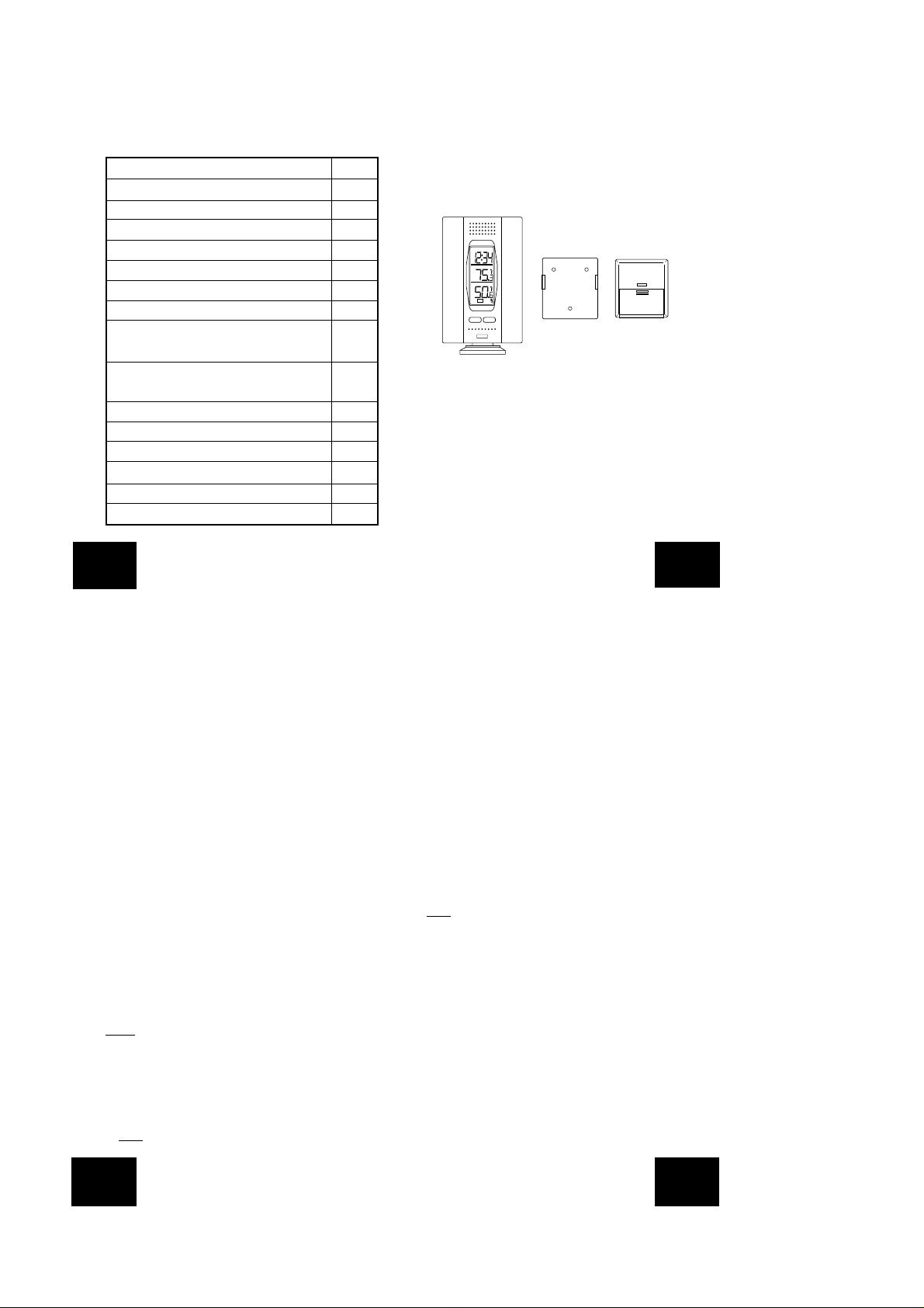
TABLE OF CONTENTS
Figure 2
REMOTE
TEMP. TRANSMITTER
433 MHz
Topic Page
Inventory of Contents 3
Quick Setup 3-5
Detailed Setup Guide
Battery Installation 6-7
Setting the Time 7-8
Selecting Units of Measurement 8
Features
Minimum and Maximum 8
Temperatures
Resetting Minimum and Maximum 9
Temperatures
Additional remote control senders (optional) 9-10
Mounting 10-11
Troubleshooting 11-12
Maintenance and Care 13
Specifications 13-14
Warranty Information 14-16
INVENTORY OF CONTENTS
1. The indoor temperature station (Figure 1)
2. The remote temperature sensor (TX2U) and mounting
bracket. (Figure 2)
3. 3 each, 1/2" Philips screws.
4. One strip of double sided adhesive tape.
5. Instruction Manual and Warranty Card.
Figure 1
TIME
INDOOR
OUTDOOR
2
SET
MIN/MAX
RESET/+
CH
433 MHz
ADDITIONAL EQUIPMENT
(not included)
1. 1 Philips screwdriver.
2. 2 Fresh AAA 1.5V batteries.
3. 2 Fresh AAA 1.5V batteries.
QUICK SETUP
Hint: Use good quality Alkaline Batteries and avoid
rechargeable batteries.
1. Have the indoor temperature station and remote
temperature sensor 3 to 5 apart.
P.2
GB
2. Batteries should be out of both units for 10 minutes.
3. Place the batteries into the remote temperature sensor
first then into the indoor temperature station.
(All remote temperature sensors must be started before
the indoor temperature station)
4. DO NOT PRESS ANY BUTTONS FOR 15 MINUTES.
In this time the indoor temperature station and remote
temperature sensor will start to talk to each other and
the display will show both the indoor temperature and
an outdoor temperature. If the indoor temperature
station does not display both temperatures after the 15
minutes please retry the set up as stated above. After
both indoor and outdoor temperatures are displayed f or
15 minutes you can place your remote temperature
sensor outdoors and set your time.
The remote temperature sensor should be placed in a dry,
shaded area. The remote temperature sensor has a r ange
of 80 feet. Any walls that the signal will have to pass
through will reduce distance. An outdoor wall or window
will have up to 20 feet of resistance and an interior w all will
have up to 10 feet of resistance. Your distance plus
resistance should not exceed 80 ft. in a straight line.
NOTE
: Fog and mist will not harm your remote temperature
sensor but direct rain must be avoided.
To complete the set up of your indoor temperature station
after the 15 minutes have passed please follow the steps
below.
1. Press and hold the "SET" button for 5 seconds.
Note
: A "12h" or "24h" will appear on the top line. ("12h"
P.3
GB
for AM/PM, "24h" for military time)
a. To change between "12h" and "24h" press and
release the "MIN/MAX" button.
b. When you have your choice shown on the display
press and release the "SET" button once.
2. Degree Fahrenheit will now show.
a. To change between Fahrenheit and Celsius, press
and release the "MIN/MAX" button.
b. When you have your choice shown on the display
press and release the "SET" button once.
3. An hour will now be flashing.
a. Press and release the "MIN/MAX" button until the
correct hour is shown.
Note
: When in the 12h mode there is "PM" displayed
under the word TIME when in the PM hours. During
the AM hours this area will be blank.
b. When the correct hour is shown, press and release
the "SET" button once.
4. A minute will now be flashing.
a. Press and release the "MIN/MAX" button until the
correct minutes are displayed.
Press and release the SET button once more and you
are done.
GB
P.4
P.5
GB
Page 3
DETAILED SETUP GUIDE
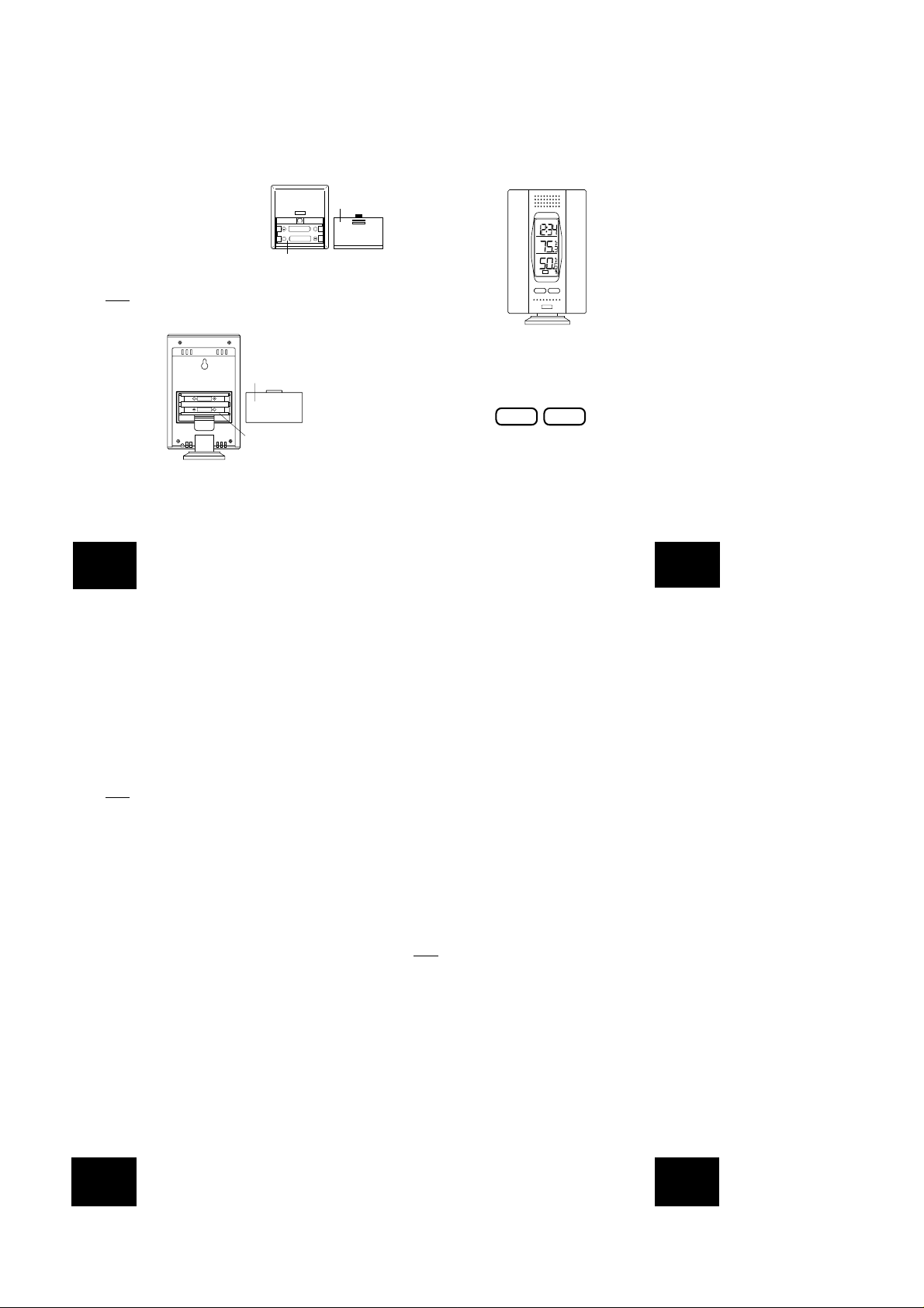
I. BATTERY INSTALLATION
A. REMOTE TEMPERATURE SENSOR
1. Remove the mounting bracket.
2. Remove battery cover
3. Observing the correct polarity,
install 2 AAA batteries-make
sure they do not spring free, or
start-up problems may occur.
Replace cover.
B. INDOOR TEMPERATURE STATION
Note
: After the batteries are installed, DO NOT press an y
buttons. This may interfere with the signals, causing
temperatures to register incorrectly.
Battery cover
SIZE AAA
+
SIZE AAA
+
Battery
compartment
1. Remove the battery cover on the backside. To do this,
push up and pull out.
2. Observing the correct polarity, install 2 AAA batteries.
3. Replace battery cover.
REMOTE
TEMP. TRANSMITTER
433 MHz
SIZE AAA LR3
+
SIZE AAA LR3
+
Battery compartment
Battery cover
4. Wait 15 minutes to allow both the indoor and outdoor
temperatures are shown on the indoor temperature
station.
5. The indoor temperature station should now show: "-:- " in the TIME LCD, and temperatures in the INDOOR
and OUTDOOR LCD's.
TIME
INDOOR
OUTDOOR
2
SET
MIN/MAX
RESET/+
CH
433 MHz
II. TIME
A. SETTING THE TIME
1. Press and hold the "SET" button for 5 second, "12h"
will appear in the TIME LCD.
SETCHMIN/MAX
RESET/+
2. Press and release the "MIN/MAX" button to select either
12h time (am/pm) or 24h time
3. Press and release the "SET" button 2 times, the hour
will flash in the upper left corner.
4. Press and release the "MIN/MAX" button to set the hours
5. Press and release the "SET" button to move to the
P.6
GB
minute setting
6. Press and release the "MIN/MAX" button to set the
minutes.
7. Press and release the "SET" button to activate the clock.
Note
: When in 12h mode, there is only a "PM" display,
which appears under "TIME." If there is no display here it
is AM. Make sure you set the time accordingly.
III. UNITS OF TEMPERATURE MEASURE
A. SELECTING UNITS OF MEASUREMENT
1. Press and hold the "SET" button for 5 second until "12h"
or "24h" appears in the TIME LCD.
2. Press and release the "SET" button again, "˚F" will
appear in the TIME LCD.
3. Press and release the "MIN/MAX" button to shift
between ˚F and ˚C.
4. Press and release the "SET" button twice to activate
settings.
IV. FEATURES
A. MINIMUM AND MAXIMUM TEMPERATURES
1. Press and release the "MIN/MAX" button, "MIN"
appears in the temperature LCD's and the recorded
minimum temperatures are displayed.
2. Press and release the "MIN/MAX" button to toggle to
the maximum temperatures. The time of occurrence of
the value for outdoor temperature will also flash.
P.7
GB
B. RESETTING THE MINIMUM AND MAXIMUM
TEMPERATURES
1. To reset both the minim um and maximum temperaturespress and hold the "RESET/+" button for 4 seconds.
C. ADDING ADDITIONAL REMOTE TEMPERATURE
SENSORS (OPTIONAL)
1. The WS-7013U is able to receive signals from 3 different
remote temperature sensors. Following are some brief
instructions for the basic set-up of remote temperature
sensor units with the WS-7013U. These extra sensors
can be purchased through the same dealer as this unit,
or by contacting La Crosse Technology directly . A TX2U
and TX6U will monitor temperature only, a TX3U will
monitor temperature and display the temperature on its
LCD, and the TX3UP will monitor the temperature via a
probe for use in pools, spas, etc.
Note
: When setting up multiple units it is important to
remove the batteries from all existing units in operation,
then to insert batteries first into all the remote temperature
sensor units, and in numeric sequence. Second, install
batteries into the indoor temperature station. Transmission
problems will arise if this is not done correctly and if the
total time for set-up exceeds 6 minutes.
2. It is necessary to remove the batteries from all units
currently in operation.
3. Remove the battery covers to all remote temperature
sensor units.
4. Place all remote temperature sensor units in a numeric
sequential order.
5. In sequential order, install batteries (follow the same
GB
P.8
P.9
GB
Page 4

-battery installation procedures seen in section "I" of
the Detailed Set-Up Guide).
6. Install batteries into the indoor temperature station.
7. Follow the Detailed Set-Up Guide for progr amming and
operating instructions.
D. VIEWING AND OPERATING WITH MULTIPLE
REMOTE TEMPERATURE SENSOR UNITS
1. To view the temperature of a different remote
temperature sensor unit, press and release the "CH"
button. A shift from one "boxed" number to the next
should be observed in the OUTDOOR LCD.
2. T o view the Minim um/Maximum temperature: first select
from which remote temperature sensor to read data
(indicated by the "boxed" number). Pressing and
releasing the "MIN/MAX" button will toggle through the
minimum and maximum indoor temperature, and the
minimum and maximum outdoor temperature.
3. To reset the Minimum/Maximum readings, press and
hold the "MIN/MAX" button for four seconds.
V. MOUNTING
Note
: To achieve a true temperature reading, avoid
mounting in direct sunlight. We recommend that y ou mount
the remote temperature sensor on an outside North-facing
wall. The sending range is 80ft; obstacles such as walls,
concrete, and large metal objects will reduce the range.
Place both units in their desired location before
permanently mounting.
A. REMOTE TEMPERATURE SENSOR
1. Remove the mounting bracket from the remote
temperature sensor
2. Mount using either screws or adhesive tape.
3. Reattach the remote temperature sensor to the
mounting bracket.
B. THE TEMPERA TURE STA TION
1. The indoor temperature station comes with the table
stand already mounted. If you wish to use the tablestand, all that is required is to place the indoor
temperature station in an appropriate location.
2. To wall mount, remove the table stand. To do this, pull
down on the stand from the rear and rotate forward.
a) Fix a screw (not included) into the desired wall, and
place the indoor temperature station onto the screw
using the hanging hole on the backside. Gently pull
the indoor temperature station down to lock the screw
into place.
TROUBLESHOOTING
NOTE
: For prob lems not solv ed, please contact La Crosse
Technology via e-mail or phone, or visit our website, www.
lacrossetechnology.com
Problem: The LCD is faint
Solution: Replace batteries
Problem: No outdoor temperature is displayed.
Solution:
1) Remove all batteries, reinsert into remote temperature
sensor first, and then into the indoor temperature station.
2) Place remote temperature sensor closer to the indoor
temperature station.
P.10
GB
3) Be sure all batteries are fresh.
4) Place remote temperature sensor and indoor
temperature station in position so the straight-line signal
is not passing through more than two or three walls.
Problem: Temperatures do not match if units are placed
Solution: Each temperature sensor is manufactured to
next to each other.
be accurate to within 1 degree plus or minus
and under normal conditions; so two
temperature sensors could be as much as 2
degrees different. However, the difference can
be exaggerated further because the
temperature sensors are designed for different
working environments. The indoor sensor is
less responsive to ambient air currents because
of the shielding effect of the display's case. In
addition, the case can act as a heat sink to
absorb and store heat from external sources (i.
e. handling of the case or radiant heat). In
addition, the much greater range of the outdoor
temperature sensor requires a different
calibration curve than the indoor range. Error
is usually greater at the extreme ends of a
range, making it harder to compare different
ranges with different curves. Under nonlaboratory conditions, it is difficult to
compensate for the above factors and obtain
an accurate comparison.
P.11
GB
MAINTENANCE AND CARE INSTRUCTIONS
• Extreme temperatures, vibration, and shock should be
avoided to prevent damage to the units.
• Clean displays and units with a soft, damp cloth. Do
not use solvents or scouring agents; they ma y mark the
displays and casings.
• Do not submerge in water.
• Do not subject the units to unnecessary heat or cold by
placing them in the oven or freezer.
• Opening the casings invalidates the warranty. Do not
try to repair the unit. Contact La Crosse Technology for
repairs.
SPECIFICATIONS
Transmitting Frequency 433MHz
Measuring Temperatures
Indoor T emperature 32˚F to 156.2˚F
Station: Indoor with 0.2˚F resolution.
Indoor T emperature -21.8˚F to 156.2˚F
Station: Outdoor with 0.2˚F resolution.
Transmitting range Maximum 80 feet (25m) open
(0˚C to 69.0˚C with
0.1˚C resolution)
(-29.9˚C to 69.0˚C with 0.1˚C
resolution)
space
GB
P.12
P.13
GB
Page 5

Temperature check
Indoor Every 10 seconds
Outdoor Twice in 10 minutes
Proof of purchase must be included if it is determined
that the weather station should be returned to La Crosse
Technology.
Batteries-(Alkaline recommended)
Remote Temperature 2 x AAA, 1.5V
Sensor
Indoor Temperature 2 x AAA, 1.5V
Station
Dimensions: (H x W x D)
Indoor T emperature 4.3” x 2.75” x .92”
Station (excluding table stand)
Remote Temperature 2.55" x 2.32" x .86"
Sensor (65 x 59 x 22mm)
Battery life Approximately 1 year
(110 x 90 x 23.6 mm)
WARRANTY INFORMATION
La Crosse Technology provides a 1-year limited warranty
on this weather station. Contact La Crosse Technology
immediately upon discovery of any defects covered by
this warranty.
Before sending the W eather Station in for repairs , contact
La Crosse Technology. The Weather Station will be
repaired or replaced with the same or similar model.
P.14
GB
LA CROSSE TECHNOLOGY WILL NOT ASSUME
LIABILITY FOR INCIDENTAL, CONSEQUENTIAL,
PUNITIVE, OR OTHER SIMILAR DAMAGES
ASSOCIATED WITH THE OPERATION OR
MALFUNCTION OF THIS WEATHER STATION. THIS
PRODUCT IS NOT TO BE USED FOR MEDICAL
PURPOSES OR FOR PUBLIC INFORMATION. THIS
PRODUCT IS NOT A T OY. KEEP OUT OF CHILDREN'S
REACH.
This warranty gives you specific legal rights. You may
also have other rights specific to your State. Some States
do no allow the exclusion of consequential or incidental
damages therefore the above exclusion of limitation may
not apply to you.
P.15
GB
For warranty work, technical support, or information contact
La Crosse Technology
190 Main Street
La Crescent, MN 55947
Phone: 507.895.7095
Fax: 507.895.8000
support@lacrossetechnology.com
sales@lacrossetechnology.com
(information on other products)
www.lacrossetechnology.com
Questions? Please see instruction video at
www.lacrossetechnology.info/7013
P.16
GB
e-mail:
(warranty work)
Website:
TABLE DES MATIERES
Sujet Page
Description du contenu 18
Guide de paramètrage rapide 19-21
Guide de paramètrage détaillé
Installation des piles 21-22
Réglage de l'heure 22-23
Sélection des unités de mesure 23
Caractéristiques
Températures minimum et maximum 23-24
Réenclenchement des températures
minimum et maximum 24
Emetteurs à distance supplémentaires
(en option) 24-25
Mise en place 26
En cas de panne 26-27
Entretien 28
Spécifications 28-29
Garantie 30-31
P.17
F
Page 6

INVENTAIRE DU CONTENU
1. Poste de température intérieure (Figure 1)
2. Capteur de température à distance (TX2U) et support
de suspension (Figure 2)
3. 3 vis cruciformes 1/2".
4. Un morceau de ruban adhésif double-face.
5. Mode d'emploi et fiche de garantie.
Fig. 1
TIME
INDOOR
OUTDOOR
2
SET
MIN/MAX
CH
RESET/+
433 MHz
Fig. 2
REMOTE
TEMP. TRANSMITTER
433 MHz
MATERIEL SUPPLEMENTAIRE
(non inclus)
1. 1 tournevis cruciforme.
2. 2 piles neuves AAA/LR3 1.5V.
3. 2 piles neuves AAA/LR6 1.5V.
P.18
F
MONTAGE RAPIDE
Conseil: Utiliser des piles alcalines de bonne qualité
et éviter les piles rechargeables.
1. Installer le poste de température intérieure et le capteur
à 3 à 5 m l'un de l'autre.
2. Sortir les piles des deux appareils pendant 10 minutes
3. Placer les piles en the batteries into the remote
temperature sensor puis dans le poste de température
intérieure.
(Tous les capteurs à distance doivent être mis en
marche avant le poste de température intérieure.)
4. N'ACTIVER AUCUNE COMMANDE PENDANT 15
MINUTES.
Durant ce laps de temps, le poste de température à
distance et le capteur à distance vont se mettre à
communiquer et l'affichage indiquera les températures
intérieure et extérieure. Si le poste de température
intérieure n'affiche pas les deux températures dans les
15 minutes qui suivent, répéter les étapes ci-dessus.
Quand les températures intérieure et extérieure sont
affichées depuis 15 minutes, mettre le capteur en place
à l'extérieure et règler l'heure.
Installer le capteur à distance dans un lieu sec et ombragé.
Cet appareil a un rayon d'action de 27m (80 pieds). Tout
mur que le signal doit traverser réduit ce rayon. Un mur
extérieur ou une fenêtre présente une résistance de 6
mètres (20pieds)et un mur intérieur présente une
résistance de 3 mètres(10 pieds). La distance entre les
appareils et la résistance ne devrait pas dépasser 27 m
(80 pieds) en ligne droite.
P.19
F
REMARQUE
: Le brouillard ou l'humidité n'auront aucun
effet sur le capteur à distance mais il faut éviter la pluie
directe.
Pour effectuer le montage du poste intérieur quand les
15 minutes se sont écoulées, suivre les étapes ci-dessous .
1. Appuyer sur "SET" pendant 5 secondes.
Remarque
: Un "12h" ou "24h" s'affichera sur la ligne
supérieure ("12h" for AM/PM, "24h" pour l'heure
militaire)
a. Pour changer entre "12h" et "24h", appuyer
brièvement sur "MIN/MAX".
b. Quand le format sélectionné s'affiche, appuyer une
fois sur "SET".
2. Les degrés Fahrenheit s'afficheront.
a. Pour alterner entre Fahrenheit et Celsius, appuyer
sur "MIN/MAX".
b. Quand le format sélectionné s'affiche, appuyer une
fois sur "SET".
3. Les heures se mettront à clignoter.
a. Appuyer sur "MIN/MAX" jusqu'à ce que les heures
correctes s'affichent.
Remarque
: Dans le mode 12h mode, un "PM" est
affiché sous le mot TIME (HEURE) l'après-midi Le
matin (AM) rien ne s'affiche.
b. Quand l'heure correcte s'affiche, appuyer une fois
sur "SET".
P.20
F
4. Les minutes se mettront à clignoter.
a. Appuyer sur "MIN/MAX" jusqu'à ce que les minutes
correctes s'affichent.
Appuyer encore une fois sur SET pour finaliser le
réglage.
GUIDE DE MONTAGE DETAILLE
I. INSTALLATION DES PILES
A. CAPTEUR DE TEMPERATURE A DISTANCE
1. Retirer le support de suspension.
2. Retirer le couvercle des piles
3. En respectant les polarités, installer deux piles AAA/
LR3-s'assurer qu'elles ne bougent pas à l'intérieur du
lgement afin d'éviter les problèmes de mise en marche.
Remettre le couvercle en place.
+
Couvercle
des piles
P.21
REMOTE
TEMP. TRANSMITTER
433 MHz
SIZE AAA LR3
SIZE AAA LR3
+
Logement des piles
F
Page 7

B. POSTE DE TEMPERATURE INTERIEURE
Remarque
: Dès que les piles sont en place, N'appuyer
sur aucune commande. Ceci risquerait d'interférer avec
les signaux et d'entraîner des relevés incorrects.
TIME
INDOOR
OUTDOOR
2
SET
MIN/MAX
RESET/+
CH
433 MHz
SIZE AAA
+
SIZE AAA
+
Couvercle
des piles
Logement
des piles
1. Retirer le couvercle des piles à l'arrière de l'appareil
en appuyant vers le haut pour le sortir.
2. En respectant les polarités, installer 2 piles AAA.
3. Remettre le couvercle en place.
4. Attendre 15 minutes jusqu'à ce que les
températures intérieures et extérieures s'affichent sur
le poste de température intérieure.
5. Le poste de température intérieure devrait afficher
"-:--" sur le LCD HEURE et les températures sur les
LCD INTERIEUR et EXTERIEUR.
SETCHMIN/MAX
RESET/+
2. Appuyer sur "MIN/MAX" pour sélectionner le format
12h (am/pm) ou 24h.
3. Appuyer deux fois sur "SET", les heures se mettront à
clignoter en haut à gauche.
4. Appuyer sur "MIN/MAX" pour règler les heures.
5. Appuyer sur "SET" pour passer au réglage des minutes
6. Appuyer sur "MIN/MAX" pour règler les minutes.
7. Appuyer sur "SET" pour activer la pendule.
Remarque
"TIME" pour indiquer l'après-midi. Rien ne s'affiche pour
AM (matin). Règler l'heure en en tenant compte.
III. UNITES DE RELEVES DE LA TEMPERATURE
A. SELECTION DES UNITES DE RELEVE
1. Appuyer sur "SET" pendant 5 secondes, jusqu'à ce
2. Appuyer encore une fois sur "SET". "˚F" s'affichera sur
3. Appuyer sur "MIN/MAX" pour alterner entre ˚F et ˚ C.
4. Appuyer deux fois sur "SET" pour activer les réglages.
: Dans le mode 12h, "PM" s'affiche sous
que "12h" ou "24h" s'affiche sur le LCD HEURE.
le LCD HEURE.
II. HEURE
A. REGLAGE DE L'HEURE
1. Appuyer sur "SET" pendant 5 secondes, "12h"
s'affichera sur le LCD HEURE.
P.22
F
2. Appuyer sur "MIN/MAX" pour passer aux températures
maximum. L'heure à laquelle la temp érature e xtérieure
a été enregistrée s'affichera aussi en clignotant.
B. REENCLENCHER LES TEMPERATURES MINIMUM
ET MAXIMUM
1. Pour réenclencher les températures minimum et
maximum-Appuyer sur "RESET/+" pendant 4
secondes.
C. ADDITION DE CAPTEURS DE TEMPERATURE A
DISTANCE (EN OPTION)
1. Le WS-7013U peut recevoir les signaux de 3 capteurs
différents. Instructions pour le montage de base des
capteurs à distance avec le WS-7013U: ces capteurs
supplémentaires peuvent s'obtenir auprès du vendeur
de cet appareil ou en contactant La Crosse Technology
directement. Un TX2U et un TX6U ne relèvent que la
température, un TX3U relève la température et l'affiche
sur son LCD et le TX3UP relève la température au
moyen d'une sonde pour utilisation dans les piscines,
stations thermales, etc.
Remarque
: Pour monter plusieurs appareils, il est
important de retirer les piles de tous les appareils en
fonctionnement, puis de mettre les piles en commencant
par tous les capteurs à distance en séquence numérique.
Ensuite, installer les piles dans le poste de température
intérieure. Des problèmes de transmission se produiront
si ceci n'est pas effectué correctement et si le temps de
paramètrage total excède 6 minutes.
IV. CARACTERISTIQUES
A. TEMPERATURES MINIMUM ET MAXIMUM
1. Appuyer sur "MIN/MAX", "MIN" s'affichera sur le LCD
et les températures minimum enregistrées s'afficheront.
P.23
2. Il est nécessaire de retirer les piles de tous les appareils
actuellement en marche.
3. Retirer le couvercle des piles de tous les capteurs à
distance.
4. Placer tous les capteurs à distance en séquence
numérique.
5. Installer les piles en ordre séquentiel, (suivre les
procédures d'installation de la section "I" du Guide de
montage détaillé).
6. Installer les piles dans le poste de température
intérieure.
7. Suivre le Guide de montage détaillé pour les
instructions de programmation et de fonctionnement.
D. LECTURE ET FONCTIONNEMENT DES CAPTEURS
DE TEMPERATURE A DIST ANCE
1. Pour voir la température d'un capteur à distance
différent, appuyer sur "CH" button. Le passage d'un
nombre "encadré" à un autre devrait s'observer sur le
LCD EXTERIEUR.
2. Pour voir la température Minimum/Maximum:
Commencer par sélectionner le capteur à distance dont
on veut obtenir les données (indiqué par le numéro
"encadré"). Appuy er sur "MIN/MAX" pour alterner entre
les températures minimum et maximum intérieures et
extérieures.
3. Pour réenclencher les relevés Minimum/Maximum,
appuyer sur "MIN/MAX" pendant quatre secondes.
F
P.24
F
P.25
F
Page 8

V. MISE EN PLACE
Remarque
éviter d'exposer l'appareil aux rayons du soleil. Nous
recommandons d'installer le capteur à distance sur un
mur orienté au nord. Le rayon d'émission est de 27 m
(80ft) mais il est diminué par les obstacles tels que murs,
béton et gros objets métalliques. Essayer les appareils
aux endroits sélectionnés avant de les fixer de façon
permanente.
A. CAPTEUR DE TEMPERATURE A DISTANCE
1. Retirer le support de suspension du capteur à distance.
2. Le mettre en place avec les vis ou le ruban adhésif.
3. Remettre le capteur à distance sur le support.
B. POSTE DE TEMPERATURE
1. Le poste de température intérieure est équipé d'un pied
2. Pour accorcher l'appareil à un mur , retirer le pied. Pour
: Pour obtenir un rele vé réel de la température,
déjà en place. Pour poser l'appareil sur une table, la
seule à faire consiste à sélectionner un lieu approprié.
ce faire, tirer le pied de l'arrière en le faisant tourner
vers l'avant.
a) Fixer une vis (non fournie) dans le mur déisré et
accrocher le poste de température intérieure sur
cette vis par le trou de suspension à l'arrière.
Appuyer doucement sur l'appareil pour le fixer sur
la vis.
EN CAS DE PANNE
REMARQUE
La Crosse Technology par courriel ou téléphone, ou visiter
: P our tous problèmes non résolus , contacter
notre site Toile www.lacrossetechnology.com
Problème: Le LCD est pâle
Solution: Changer les piles
Problème: La température extérieure ne s'affiche pas.
Solution:
1) Retirer toutes les piles puis les remettre en place en
commençant par le capteur à distance suivi du poste
intérieur.
2) Rapprocher le capteur à distance du poste de
température intérieure.
3) S'assurer que toutes les piles sont bonnes.
4) Installer le capteur à distance et le poste intérieur de
façon à ce que le signal en ligne droite ne traverse pas
plus de deux ou trois murs.
Problème: Les températures diffèrent alors que les
appareils sont à côté l'un de l'autre.
Solution: Chaque capteur de température est
fabriqué pour être exact au degré près; dans
des conditions normales, il est donc
possible que les deux appareils affichent
jusqu'à 2 degrés de différence. Cependant,
cette différence peut être amplifiée par le
fait que les deux appareils sont conçus pour
fonctionner dans des environnements
différents. Le capteur intérieur est moins
sensible aux courants d'air ambiants en
raison de l'effet protecteur du boîtier. Par
ailleurs, ce boîtier peut absorber et stocker
P.26
F
la chaleur de sources extérieures (par ex;
manipulation de l'appareil ou chaleur
irradiée). En outre, la portée beaucoup plus
étendue du capteur de température
extéreure requiert une courbe de calibrage
différente du rayon intérieur. Les erreurs
sont généralement plus importantes avec
des courbes différentes. Hors laboratoire,
il est difficile de compenser les facteurs cidessus et d'obtenir une comparaison
exacte.
ENTRETIEN
• Eviter les températuresn vibrations et chocs excessifs
qui endommageraient les appareils.
• Nettoyer affichages et boîtiers avec un chiffon doux
humide. Ne pas utiliser de produits dissolvants ou
abrasifs qui risquent de marquer affichages et boîtiers.
• Ne pas immerger dans de l'eau.
• Ne pas soumettre les appareils à des chaleurs ou froids
excessifs en les mettant dans un four ou un freezer.
• Ouvrir les boîtiers annule la garantie. Ne pas essayer
de réparer les appareils. Pour toute réparation,
contacter La Crosse Technology.
SPECIFICATIONS
Fréquence de 433MHz
transmission
P.27
Relevés de températures
Poste de température 32˚F à 156.2˚F au 0.2˚F près
intérieur: Intérieur (0˚C à 69.0˚C au 0.1˚C près)
Poste de température -21.8˚F à 156.2˚F au 0.2˚F près.
intérieur: Extérieur (-29.9˚C à 69.0˚C au 0.1˚C près)
Rayon de transmission Maximum 80 feet (25m) en
espace dégage
Relevés de température
Intérieure Toutes les 10 secondes
Extérieur Deux fois par 10 minutes
Piles-(Alcalines recommandées)
Capteur de température 2 x AAA, LR3, 1.5V
à distance
Poste de température 2 x AAA, LR3, 1.5V
intérieure
Dimensions: (H x l x L)
Poste de température 110 x 90 x 23.6 mm
intérieure (sans pied)
(4.3" x 2.75" x .92")
Capteur de température 65 x 59 x 22 mm
à distance (2.55" x 2.32" x .86")
Vie des piles Environ 1 an
F
P.28
F
P.29
F
Page 9

GARANTIE
REMOTE
TEMP. TRANSMITTER
433 MHz
Figura 2
La Crosse Technology offre une garantie limitée sur ce
poste météo. Pour tout défaut couvert par cette garantie,
contacter La Crosse technology sans délai.
Avant d'env oy er le poste météo pour réparation, contacter
La Crosse technology. Le poste météo sera réparé ou
remplacé par un modèle identique ou similaire.
En cas de retour chez La Crosse Technology, la station
météo doit être accompagnée du ticket de caisse.
La Crosse Technology
190 Main Street
La Crescent, MN 55947
Tél.: 507.895.7095
Fax: 507.895.8000
e-mail:
support@lacrossetechnology.com
(travaux sous garanti)
sales@lacrossetechnology.com
(information sur les autres produits)
LA CROSSE TECHNOLOGY DECLINE TOUTE
RESPONSABILITE POUR TOUT DOMMAGE
ACCESSOIRE, SUBSEQUENT, PUNITIF AU AUTRE,
ASSOCIE A L'UTILISA TION OU A U FONCTIONNEMENT
DE CE POSTE METEO. CE PRODUIT NE DOIT PAS
ETRE UTILISE A DES FINS MEDICALES NI POUR
L'INFORMATION DU PUBLIC. CE PRODUIT N'EST PAS
UN JOUET. LE GARDER HORS DE LA PORTEE DES
ENFANTS.
Cette garantie vous donne des droits légaux spécifiques.
Vous pouv ez aussi jouir d'autres droits spécifiques à votre
Etat. Certains Etats n'autorisent pas l'exclusion de
dommages accessoires ou subséquent auquel cas
l'exclusion ci-dessus ne vous concerne pas.
Pour les travaux sous garantie, soutien technique ou
informations, contacter La Crosse Technology à :
P.30
F
Indice de materias y contenidos
Tema Página
Inventario de contenidos 33
Ajuste rápido 34-36
Guía detallada de la puesta en marcha
o ajuste
Instalación de las baterías 36-37
Poniendo la Hora 38
Como seleccionar las unidades de
Medición 38-39
Características
Máximo y Mínimo de las Temperaturas 39
Reajuste de los Máximos y Mínimos
registros de las Temperaturas 39
Receptores/sensores adicionales a
control remoto (opcional) 39-41
Colocando/Montando 41-42
Solución de Problemas 42-43
Mantenimiento y Cuidado 44
Especificaciones 44-45
Información de la garantía 45-47
www.lacrossetechnology.com
Toile:
Vous av ez des questions? Consultez la vidéo d’instructions
sur le site:
www.lacrossetechnology.info/7013
P.31
INVENTARIO DE CONTENIDO
1. La Estación de temperatura interior (Figura 1)
2. El sensor remoto de temperatura (TX2U) y el soporte
de montaje. (Figura 2)
3. 3 tornillos Philips de 1/2".
4. Una tira de cinta de doble lado adhesivo.
5. Manual de Instrucciones y carta de Garantía.
Figura 1
TIME
INDOOR
OUTDOOR
2
MIN/MAX
SET
RESET/+
CH
433 MHz
EQUIPO ADICIONAL (No incluido)
1. 1 destornillador Philips.
2. 2 baterías AAA de 1.5V nuevas.
3. 2 baterías AAA de 1.5V nuevas.
F
S
P.32
P.33
S
Page 10

PUESTA EN FUNCIONAMIENTO RAPIDA
Sugerencia: Use baterías Alcalinas de buena calidad
y evite el uso de baterías recargables.
1. Coloque la Estación de temperatura interior y el sensor
remoto de temperatura separados por una distancia
de 3 a 5 pies.
2. Las Baterías deberán estar por fuera de ambas
unidades por 10 minutos.
3. Coloque las baterías en el sensor remoto de
temperatura primero, luego en la Estación de
temperatura interior.
(Todos los sensores remotos de temperatura deben
arrancar antes que la Estación de temperatura interior)
4. NO PRESIONE NINGUNA TECLA POR 15 MINUTOS .
En este punto la Estación de temperatura interior y el
sensor remoto de temperatura empezarán a hablarse
el uno al otro y presentarán ambas temperaturas, la
interior y la del aire libre. Si la Estación interior de
temperatura no despliega ambas temperaturas después
de 15 minutos reintente la puesta en funcionamiento
como se explicó anteriormente. Después que ambas
temperaturas, interior y al aire libre son desplegadas
por 15 minutos Usted puede colocar el sensor remoto
de temperatura al aire libre ajustar su hora.
El sensor remoto de temperatura debe ser colocado en
un área seca y sombreada. El sensor remoto de
temperatura tiene un rango de 80 pies. Cualquier pared
que la señal tenga que atravesar reducirá esta distancia.
Una pared al aire libre o una ventana harán de 20 pies de
resistencia y una pared interior hará de 10 pies de
resistencia. Su distancia más la resistencia no deberán
exceder los 80 pies en línea recta.
NOTA
: La niebla y la llovizna af ectarán a su sensor remoto
de temperatura pero la lluvia directa deberá evitarse.
Para completar la puesta en funcionamiento de su
Estación de temperatura interior después que hayan
pasado 15 minutos por favor siga los siguientes pasos.
1. Presione y sostenga la tecla "SET" por 5 segundos.
Nota
: Unas "12h" o "24h" aparecerán en la línea
superior. ("12h" para AM/PM, "24h" para hora militar)
a. Para cambiar entre "12h" y "24h" Presione y suelte
la tecla "MIN/MAX".
b. Cuando haya hecho su elección en la pantalla
Presione y suelte la tecla "SET" una vez.
2. Los grados Fahrenheit ahora se mostrarán.
a. Para cambiar entre Fahrenheit y Centígrados,
Presione y suelte la tecla "MIN/MAX".
b. Cuando Usted haya hecho su elección en la pantalla
Presione y suelte la tecla "SET" una vez.
3. La hora empezará ahora a titilar.
a. Presione y suelte la tecla "MIN/MAX" hasta que la
hora correcta es mostrada.
Nota
: Cuando está en el modo de 12h "PM" se
desplegará debajo de la palabra TIME cuando la hora
está PM. Durante las hor as de AM esta área estará en
blanco.
P.34
S
b. Cuando la hora correcta es mostrada, Presione y
suelte la tecla "SET" una vez.
4. Los minutos empezarán a titilar.
a. Presione y suelte la tecla "MIN/MAX" hasta que los
minutos correctos sean presentados.
Presione y suelte la tecla SET una vez más y estará
listo.
PUESTA EN FUNCIONAMIENTO DETALLADA
I. INSTALACION DE BATERIAS
A. SENSOR REMOTO DE TEMPERATURA
Tapa de las
REMOTE
TEMP. TRANSMITTER
SIZE AAA LR3
SIZE AAA LR3
+
Compartimiento de las pilas
1. Quite el soporte de montaje.
2. Quite la tapa de baterías
3. Verifique la polaridad correcta, e instale 2 baterías
AAA-asegúrese que no queden sueltas, o si no
problemas en la puesta en funcionamiento pueden
ocurrir. Coloque nuevamente la tapa.
pilas
433 MHz
+
P.35
B. ESTACIÓN DE TEMPERATURA INTERIOR
Note
: Después que las baterías están instaladas, NO
presione ninguna tecla. Esto puede interferir con la señal,
ocasionando que la temperatura se registre
incorrectamente.
TIME
INDOOR
OUTDOOR
2
SET
MIN/MAX
CH
RESET/+
433 MHz
+
SIZE AAA
SIZE AAA
+
Tapa de las
pilas
Compartimiento
de las pilas
1. Quite la tapa de baterías de la parte de atrás. Para
hacer esto, empuje hacia arriba y hale hacia afuera.
2. Observando la polaridad correcta, instala 2 baterías
AAA.
3. Coloque nuevamente la tapa de baterías.
4. Espere de 15 minutos hasta que ambas
temperaturas, la interior y la al aire libre, sean
presentadas en la Estación de temperatura interior.
5. La Estación de temperatura interior deberá mostrar
ahora: "-:- -" en la sección HORA LCD, y las
temperaturas en las secciones INTERIOR y AL AIRE
LIBRE.
S
P.36
S
P.37
S
Page 11

II. HORA
A. AJUSTE DE LA HORA
1. Presione y sostenga la tecla "SET" por 5 segundos,
"12h" aparecerá en la HORA LCD.
SETCHMIN/MAX
RESET/+
2. Presione y suelte la tecla "MIN/MAX" para seleccionar
entre hora de 12h (am./pm.) o la hora de las 24h
3. Presione y suelte la tecla "SET" 2 veces, la hora titilará
en la esquina superior izquierda.
4. Presione y suelte la tecla "MIN/MAX" para ajustar la
hora
5. Presione y suelte la tecla "SET" para pasar al ajuste
de los minutos
6. Presione y suelte la tecla "MIN/MAX" para ajustar los
minutos.
7. Presione y suelte la tecla "SET" para activar el reloj.
Nota
: Cuando está en el modo de 12h, sólo se desplegará
"PM", el cual aparece debajo de la palabra "TIME." No se
despliega nada si está en AM. Asegúrese que ajustó la
hora adecuadamente.
III. UNIDADES DE MEDICION DE TEMPERATURA
A. SELECCIÓN DE UNIDADES DE MEDICION
1. Presione y sostenga la tecla "SET" por 5 segundos
hasta que "12h" o "24h" aparezcan en la HORA LCD.
2. Presione y suelte la tecla "SET" otra vez, "˚F" aparecerá
en la HORA LCD.
3. Presione y suelte la tecla "MIN/MAX" para cambiar entre
˚F y ˚C.
4. Presione y suelte la tecla "SET" dos veces para activar
los ajustes.
IV. CARACTERISTICAS
A. TEMPERATURAS MÍNIMA Y MÁXIMA
1. Presione y suelte la tecla "MIN/MAX", "MIN" aparecerá
en la temperatura LCD y los registro de las temperaturas
mínimas serán desplegadas.
2. Presione y suelte la tecla "MIN/MAX" para saltar a las
temperaturas máximas. La hora de ocurrencia del v alor
para la temperatura al aire libre también titilará.
B. REINICIALIZACIÓN DE LAS TEMPERATURAS
MÍNIMA Y MÁXIMA
1. Para reinicializar las temperaturas mínima y máxima-
Presione y sostenga la tecla "RESET/+" por 4
segundos.
C. ADICION DE SENSORES REMOTOS DE
TEMPERATURA (OPCIONAL)
1. El WS-7013U es capaz de recibir señales de 3 sensores
de temperatura remotos diferentes. Siguiendo algunas
breves instrucciones para la puesta en funcionamiento
rápida de los sensores remotos de temperatura con la
WS-7013U. Estos sensores extras pueden comprarse
en el mismo distribuidor de la unidad, o contactando a
La Crosse Technology directamente. Un TX2U y un
P.38
S
TX6U solamente monitorea la temperatura, un TX3U
monitorea la temperatura y despliega la temperatura
en su pantalla LCD, y el TX3UP monitorea la
temperatura mediante una sonda se usa en piscinas,
spas, etc.
Note
: Cuando esté poniendo en funcionamiento múltiples
unidades es importante que quite las baterías de todas
las unidades existentes en operación, luego inserte primero
las baterías en todos los sensores remotos de temperatura,
y en secuencia numérica. Después, instale las baterías
en la Estación de temperatura interior. Problemas de
transmisión pueden presentarse si esto no es hecho
correctamente y si el tiempo total time de puesta en marcha
excede los 6 minutos.
2. Es necesario quitar las baterías de todas las unidades
en normal operación.
3. Quite la tapa de baterías de todos los sensores remotos
de temperatura.
4. Coloque todos los sensores remotos de temperatura
en un orden numérico secuencial.
5. En orden secuencial, instale las baterías (siga los
mismos procedimientos de instalación de baterías
vistos en la sección "I" de la Puesta en funcionamiento
Detallada).
6. Instale las baterías en la Estación de temperatura
interior.
7. Siga la Puesta en funcionamiento Detallada para su
programación e instrucciones de operación.
D. VISUALIZANDO Y OPERANDO CON SENSORES
REMOTOS DE TEMPERATURA MULTIPLES
1. Para ver la temperatura de un sensor remoto de
temperatura diferente, Presione y suelte la tecla "CH".
P.40
S
P.39
En turnos de a uno el próximo número "encajado" podrá
ser observado en la sección del LCD AL AIRE LIBRE.
2. Para ver el Mínimo / Máximo de temperatura: primero
seleccione desde cual sensor remoto de temperatura
va leer datos (indicado en el número "encajado").
Presionando y soltando la tecla "MIN/MAX" cambiará
entre la temperatura interior mínima y máxima, y la
temperatura mínima y máxima al aire libre.
3. Para reinicializar las lecturas de Mínimo /Máximo,
Presione y sostenga la tecla "MIN/MAX" por cuatro
segundos.
V. MONTAJE
Nota
: Para lograr una verdadera lectura de temperatura,
evite el Montaje en la luz solar directa. Recomendamos
que usted monte el sensor remoto de temperatura en una
pared exterior que mire al lado Norte. El rango de
transmisión es de 80 pies; obstáculos como paredes,
concreto, y objetos grandes de metal reducen el rango.
Coloque ambas unidades en su posición deseada antes
de un montaje permanente.
A. SENSOR REMOTO DE TEMPERATURA
1. Quite el soporte de montaje del sensor remoto de
temperatura
2. Monte usando los tornillos o la cinta adhesiva.
3. Asegure el sensor remoto de temperatura al soporte
de montaje.
B. LA ESTACIÓN DE TEMPERATURA
1. La Estación de temperatura interior viene con un soporte
de mesa ya montado. Si usted desea usar el soporte
P.41
S
S
Page 12

de mesa, todo lo que se requiere es colocar la Estación
de temperatura interior en una posición apropiada.
2. Para montar en la pared, Quite el soporte de la mesa.
Para hacer esto , hale hacia abajo el soporte de atrás y
gire hacia adelante.
a) Fije un tornillo (no incluido) en la pared deseada, y
coloque la Estación de temperatura interior en el
tornillo usando el agujero de montaje de la parte
posterior. Suavemente hale la Estación de
temperatura interior hacia abajo para asegurarla al
tornillo.
SOLUCION DE PROBLEMAS
NOTA
: Para problemas no resueltos, por favor contacte a
La Crosse Technology via e-mail, por teléfono, o visite
nuestro website, www.lacrossetechnology.com
Problema: La pantalla LCD es débil
Solución: Reemplace baterías
Problema: La temperatura al aire libre no se despliega.
Solución:
1) Quite todas las baterías, reinsértelas primero en el
sensor remoto de temperatura, y luego en la Estación
de temperatura interior.
2) Coloque el sensor remoto de temperatura más cerca
de la Estación de temperatura interior.
3) Asegúrese que todas las baterías sean nuevas.
4) Coloque el sensor remoto de temperatura y la Estación
de temperatura interior en una posición tal, que la señal
en línea recta no pase a través de más de dos o tres
paredes.
Problema: Las Temperaturas no concuerdan si las
unidades son colocadas una al lado de la
otra.
Solución: Cada sensor de temperatura es
manufacturado con una precisión de más o
menos 1 grado bajo condiciones normales;
Así que dos sensores de temperatura
pueden tener como mucho 2 grados de
diferencia. Sin embargo, la diferencia puede
ser exagerada adicionalmente porque los
sensores de temperatura están diseñados
para diferentes ambientes de trabajo. El
sensor interior es menos sensible a
ambientes de corrientes de aire por el
efecto de blindaje de la cubierta de la
pantalla. Además, la cubierta puede actuar
como un disipador de calor que absorbe y
almacena el calor de fuentes externas (por
Ej. manejando el calor de la cubierta o el
calor radiante). Adicionalmente, el mayor
rango del sensor de temperatura al aire libre
requiere una curva de calibración diferente
que el rango interior. El error es usualmente
mayor en los extremos de un rango,
haciendo difícil comparar diferentes rangos
con diferentes curvas. Bajo condiciones que
no sean de laboratorio, es difícil compensar
los anteriores factores y obtener una
comparación exacta.
P.42
S
INSTRUCCIONES DE MANTENIMIENTO Y
CUIDADO
• Temperaturas extremas, vibración, y golpes deberán
evitarse para prevenir daño en las unidades.
• Limpie las pantallas y unidades con un paño limpio y
suave. No use solventes o agentes abrasivos; estos
pueden rayar las pantallas y cubiertas.
• No sumerja en agua.
• No someta las unidades a calor o frío innecesario
colocándolas sobre hornos o refrigeradores.
• Abriendo las cubiertas invalida las garantías. No trate
de reparar la unidad. Contacte a La Crosse Technology
para reparaciones.
ESPECIFICACIONES
Frecuencia de 433MHz
Transmisión
Medición de Temperaturas
Estación de 32˚F a 156.2˚F con 0.2˚F
Temperatura Interior: de resolución.
Interior (0˚C a 69.0˚C con 0.1˚C de
Estación de -21.8˚F a 156.2˚F con 0.2˚F
Temperatura Interior: de resolución.
Al aire libre (-29.9˚C a 69.0˚C con 0.1˚C
Rango de TransmisiónMáximo 80 pies (25m) en
resolución)
de resolución)
espacio abierto
P.43
Verificación de Temperatura
Interior Cada 10 segundos
Al aire libre Dos veces en 10 minutos
Baterías-(Alcalinas recomendadas)
Sensor Remoto de 2 x AAA, 1.5V
Temperatura
Estación de 2 x AAA, 1.5V
Temperatura Interior
Dimensiones: (AI x An x LA)
Estación de 4.3" x 2.75" x .92"
Temperatura Interior (Excluyendo Soporte de Mesa)
(110 x 90 x 23.6 mm)
Sensor Remoto 2.55" x 2.32" x .86"
de Temperatura (65 x 59 x 22 mm)
Vida/ duración de Aproximadamente 1 año
la Batería
INFORMACION DE LA GARANTIA
La Crosse Technology le proporciona un limitado de
garantía para la estación del tiempo. Contacte a La Crosse
T echnology inmediatamente al descubrir cualquier def ecto
que este cubierto por esta garantía.
Antes de enviar la Estación del Tiempo para cualquier
reparación, contacte a La Crosse Technology . La Estación
de Tiempo se reparará o le será cambiada por el mismo
modelo o uno similar.
S
P.44
S
P.45
S
Page 13

Se debe incluir el recibo de compra si se determina que la
estación meteorológica deberá ser devuelta a La Crosse
Technology.
LA CROSSE TECHNOLOGY NO ASUMIRA NINGUINA
RESPONSABILIDAD NI OBLIGACION POR DAÑOS
INCIDENTALES, CONSECUENCIALES, PUNITIVOS, O
CUALESQUIERA OTROS DAÑOS Y PERJUICIOS
SIMILARES ASOCIADOS CON EL FUNCIONAMIENTO
O MALFUNCIONAMIENTO (FUNCIONAMIENTO
DEFECTUOSO) DE ESTA ESTACION DEL TIEMPO.
ESTE PRODUCTO NO DEBERA SER USADO PARA
PROPOSITOS MÉDICOS O PARA INFORMACION
PUBLICA. ESTE PRODUCTO NO ES UN JUGUETE.
MANTENGALO FUERA DEll ALCANCE DE LOS NIÑOS.
Esta garantía le da derechos por contrato específicos.
Puede ser que usted también tenga derecho a otros
derechos específicos de su Estado. Algunos Estados no
permite la exclusión de daños y perjuicios consecuenciales
o incidentales por lo tanto puede ser que la exclusión de
limitación arriba en mención no sea aplicada en su caso.
Para el trabajo de la garantía (reparaciones etc , asistencia
técnica, o datos de información y direcciones por favor
contacte:
P.46
S
La Crosse Technology
190 Main Street
La Crescent, MN 55947
Teléfono: 507.895.7095
Facsímil: 507.895.8000
e-mail:
support@lacrossetechnology.com
(trabajo de la garantía)
sales@lacrossetechnology.com
(Información sobre otros productos)
Página en la red:
www.lacrossetechnology.com
Preguntas? Por favor vea el video con las instrucciones
en la siguiente direccion de la red:
www.lacrossetechnology.info/7013
EJIN7013L220
P.47
S
P.48
S
 Loading...