

Page 1
Touch Screen Wireless Weather Station
WS-2510
Operating instructions
Page 2

Contents
1. General information and functioning ................................................................................ 3-5
Quick overview of the display fields on the main display ...................................................... 3-4
Weather station connection panel, mounting arrangements and battery compartment ............5
2. Preparation for operation ...................................................................................................5-9
2.1. Preparation of the weather station ........................................................................................5-6
2.2. The outdoor sensors ............................................................................................................. 6-7
2.2.1 Insertion of magnets into the outdoor sensors ..........................................................................7
2.3. Description, Installation and Commissioning of sensors ...................................................... 7-9
2.3.1 WS-2510-15 wind sensor ..........................................................................................................7
2.3.2 WS-2510-16 rainfall sensor ................................................................................................... 7-8
2.3.3 WS-2510-19 Brightness sensor ................................................................................................8
2.3.4 Addressing of sensors WS-2510-22/27/25 ...............................................................................8
2.3.5 WS-2510-22 temperature/humidity sensor ...............................................................................8
2.3.6 WS-2510-27 temperature sensor ..............................................................................................8
2.3.7 WS-2510-25 temperature/humidity sensor ...............................................................................8
2.3.8 Information on the storage of solar cell powered outdoor sensors ...........................................9
3. Operation ........................................................................................................................... 9-24
3.1. Basic settings ...................................................................................................................... 9-14
3.1.1 General settings ......................................................................................................................10
Illumination ..............................................................................................................................10
Cleaning mode ........................................................................................................................10
WWVB and sensor reception ..................................................................................................10
3.1.2 Configuration ..................................................................................................................... 10-14
Illumination time for AC adaptor operation...............................................................................11
Illumination time for battery operation......................................................................................11
Temperature display unit..........................................................................................................11
Calibration of the rainfall reading indicator ..............................................................................12
Rainfall display unit ........................................................................................................
Correction of air pressure display ............................................................................................12
Air pressure display unit ..........................................................................................................13
Keypad beep on/off .................................................................................................................13
Display type for history ............................................................................................................13
Threshold value for sunshine ..................................................................................................13
Setting the time function/day of the week/date ................................................................. 13-14
Sensor administration ..............................................................................................................14
3.2. Normal display function...................................................................................................... 15-20
3.2.1 Temperature/humidity/climate ........................................................................................... 15-16
3.2.2 Wind measurement ........................................................................................................... 16-17
3.2.3 Rainfall measurement .............................................................................................................17
3.2.4 Air pressure measurement................................................................................................. 17-18
3.2.5 Weather forecast .....................................................................................................................18
3.2.6 History display (Trend) ....................................................................................................... 18-19
3.2.7 Hours of sunshine ...................................................................................................................19
3.2.8 Brightness ...............................................................................................................................19
3.2.9 Time/Date ................................................................................................................................20
3.2.10 Special functions .....................................................................................................................20
3.3. Minimum/Maximum value display ...................................................................................... 20-21
3.4. Programming mode (entering alarm values and wake-up times) ...................................... 22-24
4. Changing batteries ................................................................................................................25
5. Information on fault removal........................................................................................... 25-26
6. Range ......................................................................................................................................26
7. Repeater for range increase .................................................................................................26
8. Maintenance and servicing information .............................................................................26
9. Technical data .......................................................................................................................27
10. Explanation of terms........................................................................................................ 27-28
11. Warranty..................................................................................................................................29
.........12
2
Page 3

1. General information and functioning
The WS-2510 Touch Screen Wireless Weather Station represents a high-quality, extremely convenient universal weather
measuring system, which can record, process and display data from up to 8 external wireless temperature and humidity
sensors, a wireless wind sensor, a wireless rainfall sensor and a wireless brightness sensor.
The operating concept of the weather station is remarkable. It does not use any operating elements, but is operated solely
via a large, touch-sensitive LC display.
The display can be illuminated permanently or on a time basis, so that it can be easily read under nearly all light
conditions.
The weather station can optionally be powered by means of batteries or with the plug-in power adaptor provided
(particularly recommended when the display is continuously lit or lit for any length of time).
The display and control possibilities of the WS-2510 at a glance:
Display of the indoor temperature (in °F or °C) and humidity
- Can be switched over to display the dew point indoors
- Storage of the minimum and maximum temperature with the time/date of occurrence
- Storage of the minimum and maximum humidity with the time/date of occurrence
- Alarms can be set for high temperature, low temperature, high humidity and low humidity
- Comfort zone indicator
- Graphical history display for the last 24 h or 8 days (user selectable)
Display of one of 8 (max.) outdoor sensors (temperature in ºF or ºC and humidity)
- Can be switched over to display the dew point or the wind chill temperature
- Storage of the minimum and maximum temperature with the time/date of occurrence
- Storage of the minimum and maximum humidity with the time/date of occurrence
- Alarms can be set for high temperature, low temperature, high humidity and low humidity
- Comfort zone indicator
- Graphical history display for the last 24 h or 8 days (user selectable)
Display of wind speed with wind direction and variation
- Wind speed units: km/h, m/s, mph, knots or Beaufort.
- Storage of the maximum wind strength with direction and time/date of occurrence
- An alarm value can be set for high wind speed
- Graphical history display for the last 24 h or 8 days (user selectable)
Display of the amount of rainfall in mm, l/m
- Can be switched between total rainfall /current hour /last hour /current day /last day
- Storage of the maximum amount per hour and per day
- Graphical history display for the last 24 h or 8 days (user selectable)
Display of the air pressure in hPa, mmHg or inHg
- Can be switched between absolute or relative (higher level of correction) air pressure
- Storage of the minimum and maximum air pressure with the time/date of occurrence
- An alarm value can be set for high air pressure and low air pressure
- Graphical history display for the last 24 h or 8 days (user selectable)
Symbolic indication of the weather forecast: rainy, cloudy, bright or sunny
Display of hours of sunshine
- Can be switched between total hours of sunshine, last day or current day
- The threshold for detecting sunshine is adjustable
- Storage of the minimum and maximum hours per day with the time/date of occurrence
- Graphical history display for the last 8 days
Display of the current brightness in the range 0 to 200 klx
- Storage of the minimum and maximum brightness with the time/date of occurrence
- Graphical history display for the last 24 h or 8 days (user selectable)
Display of the time of day, weekday and date
- 8 wake-up times can be programmed, one for each day of the week and one daily
- Integral radio-controlled clock for the synchronization of the system time of the weather station with the WWVB
sensor.
2
or inches
3
Page 4
Other
- Confirmation tone for touch screen operation can be selected to on or off.
- Can be desk mounted or wall mounted according to the design.
- Programmable time for display illumination
All important weather information appears at the same time on the display, so that operator intervention is unnecessary
for monitoring the weather situation.
Several base units can be operated at the same time and the sensor data can therefore be displayed at a number of
places at the same time.
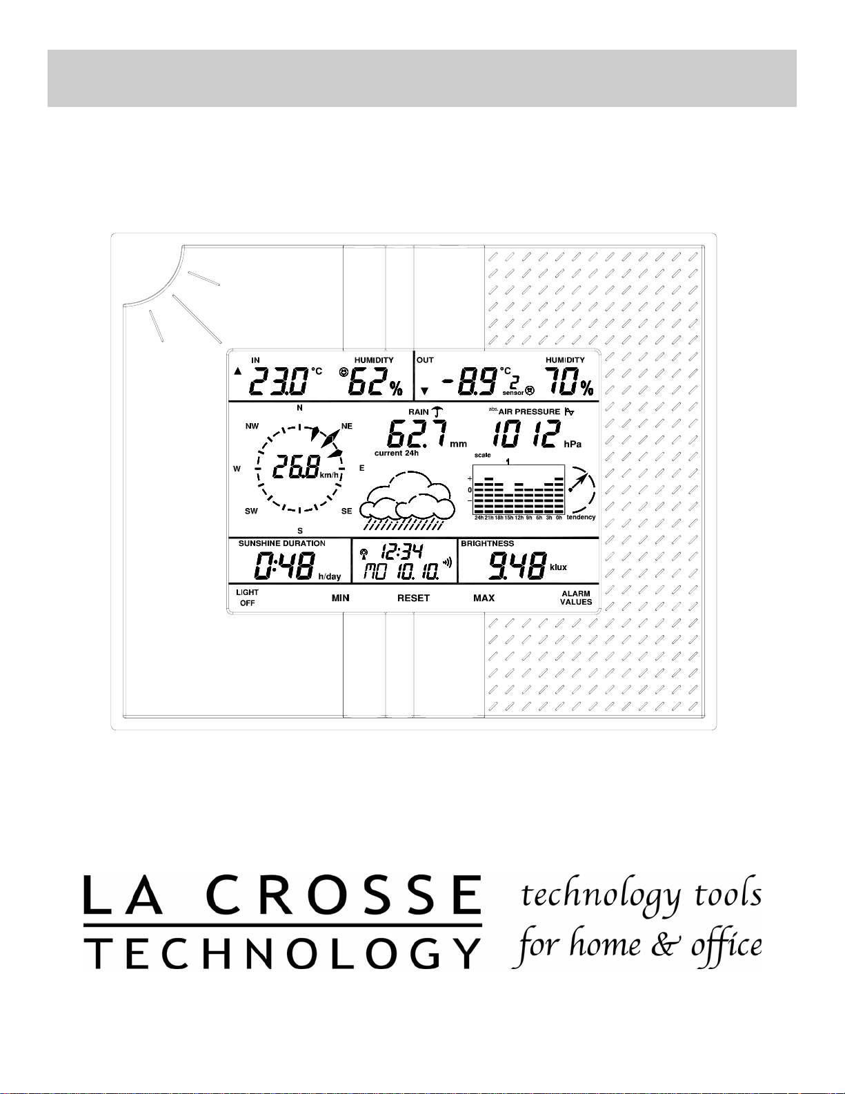
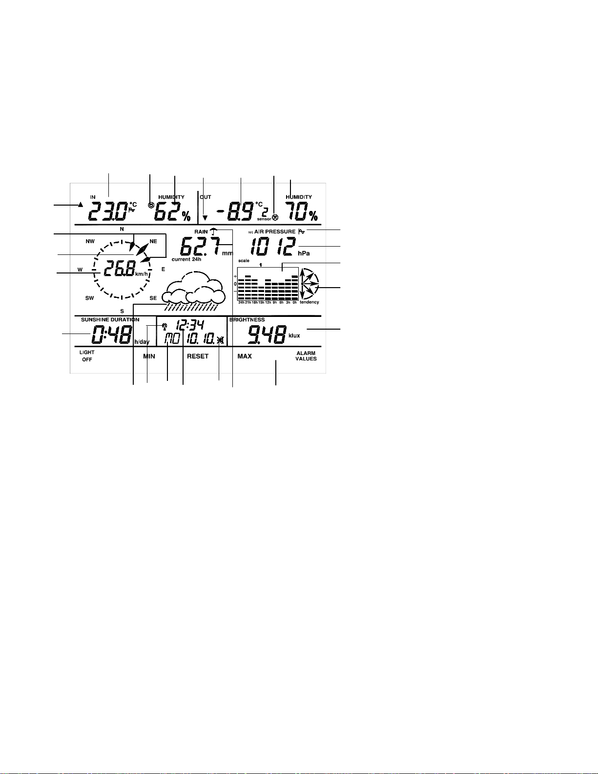
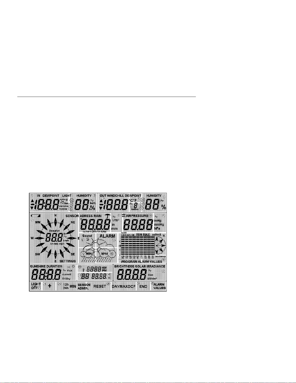
Quick overview of the display fields on the main display
1
4
2
3 1.1.
2.1.
4
3
7
6
5
12
9
11
10
13
14
19
17
15
16
18
8
20
1. Current temperature, indoor sensor
1.1. Current temperature of the selected outdoor sensor
2. Current humidity, indoor sensor
2.1. Current humidity of the selected outdoor sensor
3. Trend display for the temperature at the location of the respective sensor
4. Comfort zone indicator for the display of pleasant/unpleasant climate
5. Display of the wind speed
6. Display of the current wind direction
7. Variation range display for variable winds
8. Display of rainfall (umbrella means it is currently raining)
9. Display of the current air pressure
10. Tendency indicator for the air pressure: rising strongly, rising slightly, constant, falling slightly, falling strongly, for
more detailed description see Explanation of terms
11. History display, related in each case to the current value, see also 20
12. The symbol appears for the weather feature that has just been chosen for the history display using the Select
function, in this case air pressure
13. Display of the hours of sunshine with sun symbol if the sun is currently shining
14. Display of brightness level
15. Time display
16. Data and day of the week display
17. Display for synchronization with the WWVB radio time sensor
18. Wake-up function status indicator
19. Weather forecast display (sunny, bright, cloudy, rainy)
20. Control panel for status and special functions
The allocation of the respective units of measurement is achieved via the weather station configuration (see further
instructions).
4
Page 5
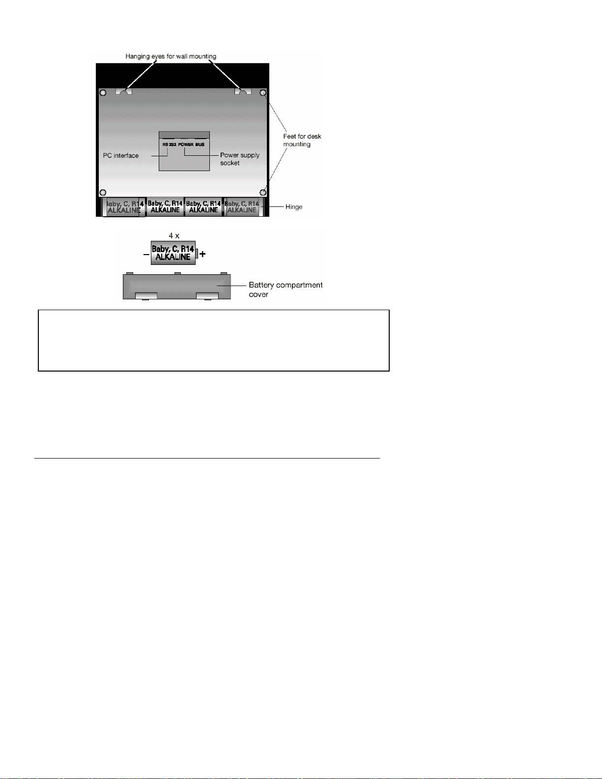
Weather station connection pane, mounting arrangements and battery compartment.
Please read these instructions carefully from start to finish before initial start
up to avoid functional breakdown and faulty operation. Keep the instructions
available for future reference.
Pay particular attention to the installation and calibration instructions for th e
instruments for recording the measured values.
The indoor/outdoor sensor system of the WS-2510 operates exclusively with wireless radio data transfer. You can set up
or mount the sensors up to 300 feet (100 m) (depending on local conditions, see section on “range”) from the base
station. Longer distances are possible using a repeater (The repeater is available from your dealer as an option).
Some outdoor sensors derive their operating voltage from built in solar cells. Pay particular attention to the set up and
assembly instructions for these components, in order to ensure correct orientation and operation.
2. Preparation for operation
2.1. Preparation of the weather station
The weather station runs on 4 C cell 1.5V alkaline batteries. As an alternative, the station can also be operated using the
power adaptor provided. This is recommended if the station illumination is to be used for extended periods. Battery
operation is recommended particularly if the display illumination is only used occasionally or for a short period. The
picture on this page shows the rear of the station with the battery compartment, the correct polarity of the batteries, the
stand and the hanging arrangement.
Battery operation
Remove the battery compartment cover by pressing in the two ridged areas simultaneously and place four C cell 1.5V
alkaline batteries in the battery compartment in the correct orientation according to the polarity markings. Close the
battery cover.
Operation using the power adaptor
First place the round female plug of the power supply provided in the power supply socket marked “POWER” on the rear
of the unit and then plug the power supply into a 110V outlet. When using the adaptor, any batteries that have been fitted
will be switched off.
PC connection (optional)
If the station is to be connected to a PC, the PC cable (optional) must be connected by means of the Western modular
plug to the socket marked “RS 232”. The 9-pin Sub-D plug is connected to a serial port of the PC.
Bus connection
The socket marked “BUS ” is for future expansions and is not used at present.
5
Page 6

Setting up/Wall mounting
Depending on requirements, the weather station can be hung on a vertical surface (wall) by means of the hanging eyes or
set up on a horizontal surface using the foldout desk stand. There are two possible latching positions (45º/60º) in the
hinge of the desk stand for when the unit is mounted on the desk. When using this method, any cables that are connected
should be laid tidily in the slots of the desk stand in order to ensure an inconspicuous and orderly routing of the cables.
Commissioning
- After the batteries have been inserted or the unit has been connected to the power supply, a short test of all the
display segments is carried out (all segments are displayed).
- Following this a short beep will be heard and the version number of the weather station will be shown in the top left of
the display.
- Next the display will go off and the weather station will go into the synchronization or initializing mode. In this mode, a
search is made both for weather sensors and also for reception of the integral radio clock (radio mast symbol
(reception indicator) flashes in the time field).
- Approximately 8 seconds after the segment test, the indoor temperature and indoor humidity will be displayed and
about 4 seconds after that the air pressure. The appropriate sensors are incorporated directly within the base station.
- The sensors (wind, rain, brightness and temperature/humidity) can now be activated. After activation, each sensor
transmits for a short period approximately for 10 minutes. This makes it easier for reception to be checked.
- If a signal from a wireless sensor is received, a short beep will be heard, the display will go off and then the
transmitted value will be displayed.
- This initialization mode is active for 35 minutes so that commissioning of all the weather sensors can be carried out. If
commissioning is finished sooner or if the station has received signals from all the sensors that have been installed
earlier, the initialization mode can also be terminated prematurely by touching any touch screen field.
However, this must never be done before the last sensor in the system has completed its test run (see following
description of sensors).
On completion of the initialization mode, the display goes off for approximately 1 second and then switches to the
normal display mode.
- In order to prevent an unintentional interruption of the initialization mode after inserting the batteries and setting up the
weather station (e.g. by accidentally touching the screen), the touch-sensitive contact surfaces are blocked against
any input for approximately 20 seconds after the batteries have been inserted.
Please note!
Previous weather sensors with software Version 1.1.
Depending on the type and the period of manufacture, the WS-2510 system sensors are supplied in two software versions
(see printing/sticker on the sensor or the packaging). The weather station is always set to Version 1.2 after
commissioning. If you are using Version 1.1 sensors (supplied before 5/2000), signals from these will not initially be
received. However, as the weather station can add new sensors to its sensor management at any time, it is possible to
add any sensors with software version 1.1.even retrospectively.
- When the weather station has automatically completed the initialization mode or the user has terminated it manually,
the configuration mode can be called up by pressing the “ALARM VALUES ” key (bottom right of the control panel) for
approximately 3 seconds.
- In this mode, next press the “SENSOR ADMIN ” key. The currently set version number for the outdoor sensors will be
displayed at the top left (factory setting 1.2).
- The version can be switched to 1.1 by touching this display field. In doing so however, signals from Version 1.2
sensors will continue to be received, the weather station being merely set up to receive signals from Version 1.1 in
addition.
- When this is done, the improved transmission reliability of Version 1.2 will be lost.
- You can subsequently exit the configuration mode by pressing the “END ” key.
- The weather station now switches to normal operation, starts trying to receive signals from all sensors for 6 minutes in
the background and inserts these automatically into the sensor administration.
2.2. The outdoor sensors
The outdoor sensors for wind and brightness measurement, for recording rainfall and for external temperature/humidity
measurement are equipped with a solar cell and a lithium backup battery to provide power during the hours of darkness
and periods of bad weather.
To prevent the batteries from discharging fully during a long period of storage without light falling on the solar cell (e.g.
when in the packaging), the power supply is activated by a small magnet that has to be inserted from the outside before
the initial start-up. Do not insert the sensor magnet until shortly before field site assembly of each sensor. Before being
used for the first time and when the battery is discharged, sensors should be exposed to strong light for one or more days
without the activation magnet being inserted so that the backup battery is charged via the solar cell.
After activation (insertion of the magnets, or batteries for battery supplied sensors), the sensors transmit for 10 minutes in
test mode. This means instead of the normal 3-minute scan, they transmit during this period in a 4-second scan. This
6
Page 7
ensures optimum reception in the initialization phase. If the signal from the sensor is unable to be received within this
time, then the reception is affected and should be improved by re-positioning the sensor.
The external temperature and humidity sensors should be addressed according to section 2.3.4.
2.2.1. Insertion of magnets into the outdoor sensors
In the WS-2510-25 and WS-2510-19 outdoor sensors, the magnet for activating the system is pressed into an opening
provided for it in the rear of the housing.
The wind sensor (WS-2510-15) is also activated by inserting a small magnet into the opening provided. The magnet
holder is located above the holding pipe fixing (opposite the solar cell).
To insert the magnet in the WS-2510-16 rain sensor press the upper section against the lower section and turn clockwise.
On the housing cover of the electronic housing incorporated into the funnel there is a slot for the small round magnet. The
rain sensor starts transmitting after pressing the magnet into the slot.
2.3. Description, Installation and Commissioning of sensors
The WS-2510 sensor design consists of two groups of sensors. The WS-2510-19 brightness sensor, the WS-2510-16
rainfall sensor and the WS-2510-15 wind sensor are permanently set to address 7 in the factory. If necessary, e.g. when
several sensor systems are operated in the immediate vicinity of one another, their address can be changed in the
factory.
The second group of sensors is the WS-2510-22, WS-2500-25 and WS-2510-27 types. A maximum of eight of this type of
sensor can be used and are selected using the sensor selection on the display. Therefore each has to be assigned an
address. For these types, be sure to observe the instructions for addressing.
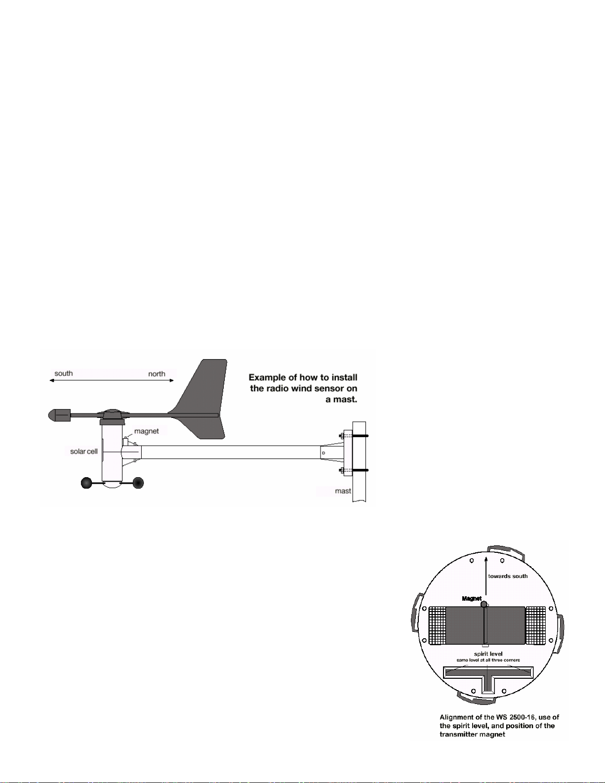
2.3.1 WS-2510-15 wind sensor
The wind sensor measures both the wind direction and the wind speed at the mounting location. It is powered by a solar
cell, and a back-up battery during the hours of darkness, and has a non-user definable address.
It is mounted either on a mast or high up on a wall. It is important at the sensor location that the solar cell in the sensor
housing faces directly south and is unshielded on all sides, i.e. the wind can reach the sensor unimpeded from all sides.
The exact alignment of the sensor to the
south is very important as this alignment
acts as reference for the wind directional
measuring device.
In order to obtain precise measurements
ensure that the sensor is mounted
vertically in the mounting tube.
Finally screw the mounting tube and the
sensor together to ensure a firm base for
all the components.
In its basic form the wind sensor should
be aligned in the north-south direction
(solar cell to the south), in order to
provide the precise north reference for the
evaluation electronics.
2.3.2 WS-2510-16 rain sensor
The rain sensor is also powered by solar energy and has an address that cannot be
changed by the user.
In this case the alignment of the solar cell is directly towards the south.
The rain sensor should be secured to an exactly horizontal surface using the
securing holes at the base of the housing. First remove the upper part by pressing
against the lower part and turning clockwise. In the lower part is a depression that,
when filled with water, permits a precise horizontal alignment without additional
assistance.
Pour a small amount of water into this depression and align the lower section of the
housing using the spirit level principle. After marking the exact installation location
the water can be removed. Note the south alignment for the solar cell. The shank of
the built-in spirit level must point to the north (see diagram).
To obtain the best possible wireless emissions (high range) it is advisable not to
place the rain sensor directly on the ground. By mounting the sensor about 3 feet (1
m) above the ground the danger of soiling (especially the solar cells) is reduced.
After screwing on the lower part to the base secure the upper part as follows:
There is a bar magnet centrally located on the side on the counting rocker for the
water level in the base. The bar magnet initiates the counting pulses to the
7
Page 8
electronics. The upper part of the housing can now be placed so that the solar cell is on the same side as the magnet,
with the electronic part directly opposite it, with the three catches fitting neatly into the holding devices in the lower part.
Finally turn the upper part gently anti-clockwise until it securely slots into holding devices of the lower part.
The rain sensor is then ready for operation. As a test pour a little water gently into the funnel. The amount collected will
then be converted in the base unit to inches, litres/m
2.3.3. Brightness sensor WS-2510-19
The brightness sensor detects the brightness at the current location in a range between 0 and 200000 lux. It is powered
by an integral solar cell and also has a fixed address. To mount the sensor, the plastic point is inserted on one side of the
aluminum tube supplied and the sensor is fitted on the other side of the tube. The sensor can now be inserted into the
ground. Depending on the firmness of the ground, the earth spike should be inserted so that the sensor is about 8-12
inches (20-30 cm) above the ground to avoid it becoming dirty due to mud splashing up onto it.
The sensor should be turned so that the solar cell points to the south. The location must be free from shadows and the
sun able to shine directly onto the measuring head. The sensor must be mounted vertically with the measuring head at
the top.
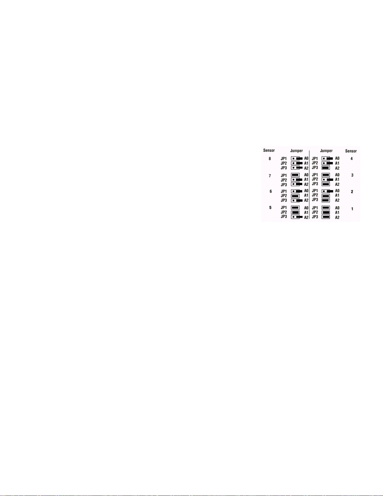
2.3.4 Addressing of the temperature/humidity sensors WS-2510-22, WS-2510-25 , and WS-2510-27
The outdoor sensor concept enables the concurrent deployment of up to eight
outdoor sensors, whose data can be selected by the user to appear in the top right
hand field of the display. Each sensor in the system is assigned a sensor address,
which enables the receiver to integrate the sensor into the total system without any
problems. Each sensor delivered is set to sensor 1. The programmable allocation is
clear from the diagram.
The addressing can be self-generated by means of coding bridges on the
conductive side of the sensor board. To do this on the WS-2510-25 unscrew the
protective bell housing on the sensor housing and open the housing by removing
the screws on the rear.
The WS-2510-22/27 types only require the housing rear wall to be unscrewed.
The coding bridges must then be set according to the address table.
2.3.5 WS-2510-22 temperature/humidity sensor
The WS-2510-22 contains a temperature and a humidity sensor. This sensor is freely addressable for displaying within
the display field at the top right of the display (see display overview on page 4). The addressing can be set individually
according to section 2.3.4. Since it is exclusively battery operated this sensor is suitable for use in (dark) inner rooms such
as a garage, a wine cellar or loft.
2.3.6 WS-2510-27 temperature/humidity sensor
The WS-2510-27 requires two AA alkaline batteries for operation. It enables the recording of garden, pond or ground
temperatures or similar by means of an encapsulated temperature sensor, remotely connected to the electronics by a 10
foot (3 m) cable.
This sensor can also be freely addressed for displaying within the display field at the top of the display (see display
overview on page 4). The addressing can be set individually according to section 2.3.4.
Now you can mount or position the electronics housing at the required location and place the temperature sensor on or in
the required object.
2.3.7 WS-2510-25 temperature/humidity outdoor sensor
The WS-2510-25 outdoor sensor enables the transmission of the temperature and humidity at the sensor location.
This sensor can also be freely addressed for displaying within the display field at the top of the display (see display
overview on page 4). All WS-2510-25 sensors are set at the factory to sensor 1. In accordance with section
2.3.4.individual addressing is also possible.
The sensor should be mounted on the north or west side as meteorological temperature recording normally takes place
“in shadow ”. It can also be placed at other locations if desired. You only need to make sure that the solar cell that
provides the sensor with power is permanently aligned towards the light. The sensor must not be shaded by dense
obstructions such as leaves, etc., which could impair the power supply from the solar cell. However, the solar cell does
not have to be exposed to direct sunlight. The ambient brightness is sufficient to charge the battery.
A possible location for installation is under the eaves of the roof.
The sensor is designed for wall and mast mounting and should be mounted as follows: Attach the sensor wall bracket
either exactly vertically to a wall using the four screws, or to a mast using the securing clamp provided.
Position the sensor on the wall bracket and screw the two parts together using the screw provided.
When doing this, the large protective bell housing must be at the top and the solar cell must be pointing towards the light.
During the hours of darkness and periods of bad weather with relatively little sunlight an internal battery system, which is
charged by the solar cell during periods of sunshine, provides the power for the sensor.
2
or mm and displayed.
8
Page 9
2.3.8 Information on the storage of solar cell powered outdoor sensors
These sensors receive their operating voltage from a solar cell that charges an internal battery to provide power for
periods of darkness and bad weather.
If one of these sensors is out of action for some time and does not receive any light this has no affect on the internal
battery, provided the magnets designed to activate the operating voltage are removed.
Therefore the sensor can be stored for several months in its packaging, for example.
After this however, the internal battery must be charged again before being put back into operation. To do this, the sensor
must be exposed to strong light for several days without the activation magnet in order to charge the battery via the solar
cell.
3. Operation
After the installation of the wireless sensors and the subsequent commissioning of the base unit, the transmitted and
converted data appears in the appropriate fields of the display. If the displays do not appear you will find information on
fixing faults in section 5 (faults).
Please note that the only data that can be displayed is that for which the appropriate sensors have been installed.
There can be no display of rainfall without a rain sensor, for example.
As all relevant data appears on the screen concurrently, operation is essentially restricted to the simple selection
of further sensors or weather data by gently touching the appropriate dis play field.
Overview of the weather station touch screen fields.
The display is subdivided into 29 touch screen fields, which are not all active at the same time. The touch screen fields
provided in the bottom line of controls are only active when their text appears. The appearance of the remaining touch
screen fields is dependent upon the operating mode of the station.
Every time a currently valid (active) touch screen field is pressed, a short beep will be heard. If required, this can be
switched off in the configuration mode.
3.1. Basic settings, Configuration
The weather station is delivered in a condition that allows you to use its basic functions immediately after commissioning
without further adjustment. It can be adapted to suit individual requirements by means of further settings and
configuration.
9
Page 10

3.1.1. General settings
Illumination settings
To switch on the illumination, press any touch screen field on the display. The illumination will now remain switched on for
the programmed time (after the last key press).
As standard, the illumination is active for 10s with battery operation and continuously on when using the AC power
adaptor.
To switch off the illumination manually, press the “LIGHT OFF” key (bottom left, field 23).
The times for the illumination can be set up in configuration mode.
Cleaning mode
As the display becomes dirty in use, it must be cleaned from time to time with a dry linen cloth (a cloth for cleaning eye
glasses is most suitable, do not use cleaning fluids as the display could be damaged). In order that the set-up of the
station is not altered when wiping the display, there is a cleaning mode where all touch screen fields are blocked for 30s.
To activate the cleaning mode, press the top right hand touch screen field “HUMIDITY ” (field 6) for approximately
4seconds.
The display will then go off and only the time will be displayed. The display can now be cleaned.
The normal display is resumed after 30s.
WWVB and sensor reception
Every day at 3 o’clock a WWVB reception is initiated as long as this has not been deactivated. If reception is not possible
at this time, further attempts are made at 4:00, 5:00 and 6:00 o’clock.
HF sensor synchronization takes place each morning at 7:30 for 6 minutes. During this phase, new sensors or lost
sensors are automatically recorded in the reception administration.
If a signal from a sensor is not received for approximately 12 hours (240 reception failures), then “ – – – ” will be displayed
instead of the value. No further attempts will be made to receive the signal from the sensor.
However, if the sensor should be detected again at any time, it will be re-recorded in the weather station’s sensor
administration at 7:30 in the morning (synchronization phase).
3.1.2. Configuration
Many of the weather station ’s parameters can be set up manually and individually in configuration mode:
- Illumination time for AC adaptor operation
- Illumination time for battery operation
- Rainfall per rocker stroke
- Air pressure correction
- Temperature display unit
- Rainfall display unit
- Air pressure display units
- Key confirmation tone
- Form of presentation for the history display
- Threshold value for registering sunshine
- Setting of date and time
- Sensor administration
The configuration mode is activated by pressing touch screen field 29, “ALARM VALUES”, for 3 seconds. The following
diagram shows an example of a display with the configuration mode activated.
You can exit the configuration mode by pressing the “END ” key.
10
Page 11

Illumination time for AC adaptor operation
The illumination time for AC adaptor operation (“line”) is displayed in the “LIGHT” field (touch screen field 1). A setting
here is only meaningful when the weather station is powered by means of the AC adaptor power supply.
The time displayed shows in hours and minutes how long the display is to remain lit after the last touch screen field has
been pressed.
A value of 0:00 means that the illumination will never come on.
A value of -:-- (appears after 9:59) means that the illumination will stay on continuously until it is turned off manually
(“LIGHT OFF” in the main display).
- Touch screen field 1 must be pressed in order to set the required ON time.
- The associated display will now flash:
- The required value between 0:00 and 9:59 as well as “-:--” can now be set using the touch screen fields “+” and “–”.It
- When the required value has been set, you can exit set-up by pressing the “END” key. The value is now stored.
Illumination time for battery operation
The illumination time for battery operation (“batt”) is displayed in the “LIGHT” field (touch screen field 2). A setting here is
only meaningful when the weather station is powered exclusively by batteries.
The time displayed shows in seconds (up to 99) how long the display is to remain lit after the last touch screen field has
been pressed.
A value of 0 means that the illumination will never come on.
- Touch screen field 2 must be pressed in order to set the required ON time.
- The associated display will now flash:
- The required value between 0 and 99 seconds can now be set using the touch screen fields “+” and “–”. It is possible
- When the required value has been set, you can exit set-up by pressing the “END” key. The value is now stored.
Setting the temperature display units
The display units for temperature are shown in touch screen field 4 at the top right.
The factory setting is ºF.
- By touching field 4 the display units can be switched between ºF and ºC.
and the lower touch screen field will change to the following form:
is possible to run through the display more quickly by pressing the relevant touch screen field for longer.
and the lower touch screen field will change to the following form:
to run through the display more quickly by pressing for longer.
11
Page 12

Calibration of the rainfall reading indicator
The rainfall measuring system is delivered with a very high accuracy, so that normally no calibration is required.
A calibration only becomes necessary when very high accuracy is required for profess ional use or for special
purposes.
Before starting the calibration of the rainfall reading indicator, set any existing summed rainfall value in the normal display
mode back to zero (see section “Rainfall measurement“).
For the exact calibration proceed as follows:
1. Allow 100 ml of water to trickle continuously and distributed evenly into the funnel over a period of 10 minutes. In
doing so, there must be a period of at least 15 seconds between the individual rocker movements. If the rocker tilts
more quickly, the amount of water flowing through is too great and the flow must be reduced.
2. After the water has completely run through, it is necessary to wait for a further period of 6 minutes. The total amount
indicated should now be 7.5 l/m
2
.
3. If a different value is displayed, then the rocker value should be recalculated as follows:
New rocker value = 7.5 x current rocker value
Actual value (display when filled with water)
The calibration value of the rainfall per rocker stroke for the rain sensor is shown in touch screen field 8 (top center). It is
always given in ml/rocker stroke, the units on the right are the units for the subsequent display of rainfall!
The factory setting is 300ml/rocker stroke. Please note: This value is reset automatically after an initialization.
- Touch screen field 8 (RAIN) must be pressed in order to set the required value.
- The associated display will now flash:
and the lower touch screen field will change to the following form:
- The required value between 10 and 999 ml/rocker can now be set using the touch screen fields “+” and “–”. It is
possible to run through the display more quickly by pressing for longer.
- When the required value has been set, you can exit set-up by pressing the “END” key. The value is now stored.
Setting the rainfall display units
The display units for rainfall are shown in touch screen field 9 on the right hand side next to the calibration value for the
rainfall. The factory setting is l/m
- By touching field 9 the display units can be switched between l/m
2
.
2
, mm or inches.
Air pressure display correction
If the current relative air pressure at the place of installation is known (meteorological office, Internet, TV weather station,
etc.), this can be set up accurately. It deviates from the general air pressure referred to sea level given in weather reports
covering large areas depending upon the height above mean sea level. You will find a detailed explanation of this in the
section “Explanation of terms”
- Touch screen field 10 (AIR PRESSURE) must be pressed in order to set the current value.
- The associated display will now flash:
and the lower touch screen field will change to the following form:
- The value currently known can now be set using the touch screen fields “+” and “–”. It is possible to run through the
display more quickly by pressing for longer.
- When the required value has been set, you can exit set-up by pressing the “END” key. The value is now stored.
12
Page 13

Setting the air pressure display units
The display units for air pressure are shown in touch screen field 11 on the right hand side next to the air pressure value.
The factory setting is hPa.
- By touching field 11 the display units can be switched between hPa, mmHg or inHg.
Keypad beep on/off
- The keypad beep can be switched on (Sound on) or off (Sound off) by touching field 12.
Setting the display type for the history (trend display)
- By touching field 16 the history display can be switched between a bar and a line display.
Bar display Line display
Setting the sunshine threshold value
The set up field enables the brightness threshold to be set, above which the light striking the brightness sensor is to be
interpreted as sunshine. This threshold can be set between 1 and 99 klux and is set in the factory to 20 klux.
A value above the set value is counted as sunshine and is indicated by the little sun symbol in the “SUNSHINE
DURATION” display field.
This value corresponds to the threshold value generally used in meteorology for registering the hours of sunshine.
- Touch screen field 19 (SUNSHINE DURATION) must be pressed in order to set the required threshold value.
- The associated display will now flash:
- The required value can now be set using the touch screen fields “+” and “–”. It is possible to run through the display
- When the value has been set, you can exit set-up by pressing the “END” key. The value is now stored.
On its part, the brightness sensor also determines a sunshine duration referred to a fixed threshold of 20 klux. If a
threshold of 20 klux is set at the base station, it takes the value transmitted by the sensor for its further calculations. The
advantage of this is that breaks in reception have no effect on the measured value.
Setting the time function
The time of day, AM/PM indication (for 12h display) and the activated WWVB receiving function (radio mast symbol) are
displayed in touch screen field 20.
- Touch screen field 20 must be pressed in order to make the required settings.
- The time of day display will now flash:
German (24 h): or English (12 h)
- The required time can now be set using the touch screen fields “+” and “–”. It is possible to run through the display
and the lower touch screen field will change to the following
more quickly by pressing for longer.
and the lower touch screen field will change to the following form:
more quickly by pressing for longer.
13
Page 14

The seconds are automatically set to zero.
- The WWVB reception can also be switched on or off by means of the “WWVB” touch screen field as long as the time
is flashing (radio mast symbol on or off respectively).
- In addition, it now possible to select the display format for the time, date and day of the week between military and
standard format using the “12/24h” touch screen field.
- When all the settings have been made, you can exit set-up by pressing the “END” key. The clock will now be started
(seconds start automatically from zero).
Please note:
Reception of the WWVB time transmission signal is possible within a radius of approx. 2000 miles of Ft. Collins, Co.
Outside this range, the clock is set manually and runs as an equally precise quartz clock.
Setting the day and the date
The date and the day of the week are displayed in touch screen field 21.
- Touch screen field 21 must be pressed in order to make the required settings.
- The date display will now flash:
German (24 h): or English (12 h).
and the lower touch screen field will change to the following form:
- The date can now be set using the touch screen fields “+” and “–”. It is possible to run through the display more
quickly by pressing for longer.
- The day of the week can also be selected using touch screen field 27 (DAY) as long as the date is flashing.
- In addition, it now possible to select the display format for the time, date and day of the week between military and
standard format using the “12/24h” touch screen field.
Please note: The whole of the display changes each time, i.e. the time, date format and language for the day of the
week display.
- When all the settings have been made, you can exit set-up by pressing the “END” key.
Sensor administration
Sensor administration is called up by pressing the “SENSOR ADMIN” touch screen field:
4
2
1
3
Here you can set the following parameters:
- Address for the rain (1), wind (2) and brightness sensors (3) if deviating from address 7. If an address is changed
here, after leaving the configuration mode, the weather station will carry out a complete sensor synchronization for 6
minutes (as at 7:30 in the morning).
- Sensor protocol version (4).
1.Sensor addresses
The sensor addresses can be set up by touching the associated field (0 to 7).
2.Protocol version
The sensor protocol version can be changed over between 1.1 and 1.2 by touching the “Version” field (field 1)(for an
explanation see section on Commissioning, page 6).
14
Page 15

3.2. Normal display function
The diagram below shows an example of the normal weather station display. In the following description of the individual
display fields, the meaning of the display is always explained first and in some cases the necessary operating actions
followed by any available key functions so that you can get a quick overview of the display and control options for each
value.
3.2.1. Temperature/Humidity/Climatic conditions
3.2.1.1. Indoor sensor (field 1/2)
4
5
3
1
2
2
6
1
4
6
The top left hand field of the display is associated with the indoor sensor. It displays the following information from left to
right:
1. Tendency arrow symbols Indication of the tendency of the indoor temperature compared with the last value
received: rising (arrow pointing upwards) or falling (arrow pointing downwards).
2. Alternative display of the current temperature (see example left) or corresponding dewpoint (“Dewpoint”, see
example right).
3. Here, the “Graph” symbol shows that the trend display for the indoor temperature has been selected in the
history field. It only appears if it has previously been selected (see 3.2.6.:“History ”). The trend can also be displayed
for the humidity.
4. Temperature display units. Depending on selection in configuration mode.
5. Comfort indicator: Display of the climatic conditions by means of three face symbols. You will find the appropriate
data for interpreting these symbols in the section “Explanation of terms”. The comfort indicator is only displayed when
the temperature is displayed.
6. Relative humidity at the location of the weather station in percent.
Key functions (Allocation of touch screen fields, see page 9)
Pressing touch screen field 1 switches over between the temperature and the dew point display.
15
Page 16

3.2.1.2. Outdoor sensors (fields 3 to 6)
2
1
3 4
5
6
2
1
7
4
4
3
6
7
2
6
3
7
The top right hand field of the display is associated with the outdoor wireless sensors for temperature/humidity. It displays
the following information from left to right:
1. Tendency arrow symbols: Indication of the tendency of the temperature at the location of the selected outdoor
sensor compared with the last value received: rising (arrow pointing upwards) or falling (arrow pointing downwards).
2. Alternative display of the current temperature (see example left), perceived temperature (“Wind chill”, see example
right) or dew point (“Dew point”, see example bottom center) for the currently selected sensor.
3. Here, the “Graph” symbol shows that the trend display for the currently displayed outdoor temperature has been
selected in the history field. It only appears if it has previously been selected (see 3.2.6.:“History ”). The trend can also
be displayed for the humidity.
4. Temperature display units. ºC or ºF depending on selection in configuration mode.
5. Comfort indicator: Display of the ambient climatic conditions at the selected sensor by means of three face symbols.
You will find the appropriate data for interpreting these symbols in the section “Explanation of terms”. The comfort
indicator is only displayed when the temperature is displayed.
6. Relative humidity at the location of the currently selected sensor in percent.
7. Indication of the current outdoor sensor selected. If there is only one outdoor sensor available, this display field is
not used.
Please note:
If a sensor does not support humidity monitoring, the text “Humidity”, the percent sign and the comfort indicator will not be
displayed.
Key functions (Allocation of touch screen fields, see page 9)
- Touch screen field 3 switches over between the display of temperature, perceived temperature and dew point.
- Touch screen field 4 selects the next sensor if available (1 …8)
- Touch screen field 5 selects the previous sensor if available (8 …1)
3.2.2. Wind measurement (field 7)
The display field for the wind measurement is situated in the middle on the left.
Here the main wind direction, the range of variation of wind direction and the wind speed are displayed.
2
2
1
3
4
3
2
1
2
3
1
1. The main wind direction is shown by the double-headed arrow on the wind compass rose.
2. If there is a variation in wind direction this is shown by means of several single-headed arrows to the left and right
of the main wind direction (max.3 in each direction).
3. Depending on the selection, the wind speed in km/h, m/s, mph, knots or Beaufort or the numerical value of the wind
direction in degrees of a full circle is shown in the center of the wind compass rose.
16
Page 17
4. Here, the “Graph” symbol shows that the trend display for the wind direction has been selected in the history
field. It only appears if it has previously been selected (see 3.2.6.:“History”). The trend can be displayed in km/h, m/s,
mph or knots. However, if Beaufort or degrees have been chosen for the main display, any trend available will be
shown in km/h.
Key functions (Allocation of touch screen fields, see page 9)
- Touch screen field 7 switches over between the units for wind speed and the display of numerical wind direction.
The switching sequence is: km/h, m/s, mph, knots, Beaufort, numerical value of wind direction in degrees.
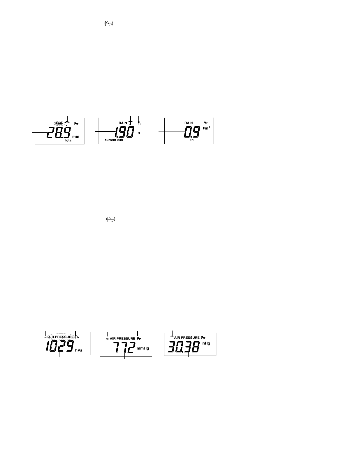
3.2.3. Rainfall measurement (fields 8/9)
The display field for the rainfall measurement is situated in the middle at the top.
Here, the amount of rain collected in the rainfall sensor and the current rainfall (rainfall in the last quarter of an hour) are
displayed.
3
2
2
3
1
1
1
1. The rainfall is either displayed as a total (“total”; since the last deletion), the last hour
(“1h”), the last day (“24h”) or the current day (“current 24h”).
The following particular features should be noted:
The rainfall for the “last hour ” is always calculated on the half hour, e.g. between 14:30 and 15:30.
The rainfall for the “last day” is always calculated at 7:30.
The rainfall for the “current hour/day” is calculated from the accumulated stored values for the “last hour/day”.
As a result of internal checking functions, the display of the rainfall is delayed by between 3 and 12 minutes.
2. Umbrella symbol: shows current rain, i.e. if the rainfall sensor has reported an amount of rain within the last 15
minutes, which is above the trigger point for the rainfall sensor.
3. Here, the “Graph ” symbol shows that the trend display for the rainfall has been selected in the history field. It
only appears if it has previously been selected (see 3.2.6.: “History”).
Key functions (Allocation of touch screen fields, see page 9)
- Touch screen fields 8 and 9 switch over the display mode.
The switching sequence is:
Total, current hour, last hour, current day, last day.
- If touch screen field 26 (“RESET”) is pressed briefly, the point in time at which the total rainfall data were last deleted
will be displayed in the date and time field.
- If touch screen field 26 (“RESET”) is pressed for 3 seconds, the total rainfall value will be deleted.
3.2.4. Air pressure measurement (fields 10/11)
The display field for the air pressure measurement is situated in the middle at the top right hand side (“AIR PRESSURE”).
Here, the current air pressure at the location of the weather station is displayed with one of three possible units.
2
3
2
3
2
3
1
1
1
1. Depending on the setting in the configuration mode, the air pressure is displayed in hPa, mmHg or inHg.
2. Either the relative air pressure (value corrected for height, see corresponding setting in configuration mode and the
explanation in the section “Explanation of terms”) or the absolute air pressure (the uncorrected output value from the
sensor, right hand diagram) can be displayed.
17
Page 18
3. Here, the “Graph” symbol shows that the trend display for the air pressure has been selected in the history
field. It only appears if it has previously been selected (see section on “History ”).
If the air pressure history is active, then the tendency indicator for the development of the air pressure will also appear
next to it on the right.
Key functions (Allocation of touch screen fields, see page 9)
- You can switch between displaying the absolute and the relative air pressure using touch screen fields 10 and 11.
Please note!
A difference between the absolute and relative air pressure will only be displayed when the height-corrected value for
the relative air pressure has previously been entered.
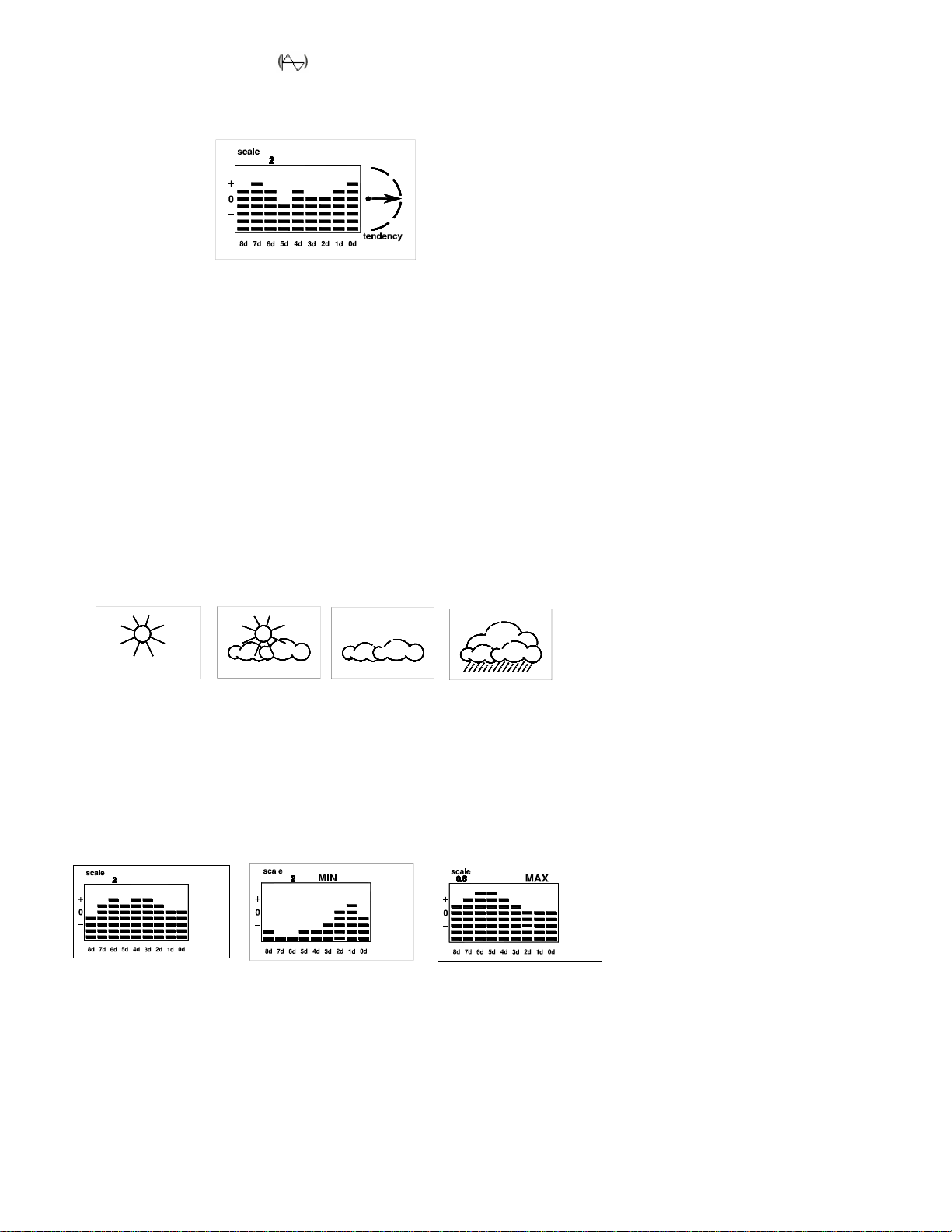
3.2.5. Weather forecast
Based on years of experience in the development of weather measurement technology, the weather forecast algorithms
for the actual operating location of the weather station are very sophisticated and reliable. Owing to comprehensive data
capture, the calculation of weather tendencies is accurate enough for these types of devices as well, so that, for example,
the weather station will not be “fooled” by a short period of sunshine just before a long period of rainy weather sets in.
The comprehensive nature of the forecast depends also on the location of the sensors; in flat countryside a
comprehensive forecast of this sort is possible, whereas in mountainous regions the conditions change more frequently
and are more localized.
The weather forecast is shown in the middle of the display underneath the rainfall indication by means of easily
remembered weather symbols.
Sunny Bright Cloudy Rainy
There are no function keys available for this item.
3.2.6. History display (Trend, fields 16-18)
The display field for histories is situated in the middle at the right hand side beneath the air pressure display. Here, the
trend of the values for a selected weather feature is displayed in three ways:
Normal trend display Minimum trend display Maximum trend display
The trend values for the
last 24 h or for the last
8 days are displayed.
The minimum values for
the last 8 days are
displayed.
The maximum values
the last 8 days are
displayed.
- The sensor for which the trend is to be displayed is selected by first pressing touch screen field 16.
- The request “SELECT ” then appears.
- The field is then touched for which the trend is to be displayed.
- The display mode is switched over between the trend for the last 8 days and the last 24h using touch screen fields 17
and 18.
- The respective scale factor is shown above the graphical trend display. The different scaling is necessary in order to
be able to clearly show large variations and different trends within the available graphics field.
18
Page 19

Please note:
- With temperature and pressure, the history is shown referred to the current value.
Here the display can optionally be in the form of a bar or line diagram according to the setting in the configuration
mode.
- With humidity, wind speed, rainfall, hours of sunshine (8-day trend only) and brightness, the history is shown as the
absolute value with the bottom line as the zero reference. In this case the display is always in the form of a bar
diagram.
Key functions (Allocation of touch screen fields, see page 9)
- Touch screen field 16 activates the selection mode (“SELECT”)
- Touch screen fields 17 and 18 switch over the display mode (8 days/24 h).
3.2.7. Hours of sunshine
The display field for the hours of sunshine (SUNSHINE DURATION) is situated at the bottom left of the display. Here the
hours of sunshine are displayed in three ways:
Total: Last day Current day
2
3
2
1
3
1
1
1. The hours of sunshine are either displayed as a total (“h”; since the last deletion), the last hour (“h/day”) or the
current day (“current h/day”).
The following particular features should be noted:
The hours of sunshine for the “last day” are always calculated at 0:00 hours.
2. Here, the “Graph” symbol shows that the trend display for the hours of sunshine has been selected in the
history field. It only appears if it has previously been selected (see 3.2.6.:“History”). Only the 8-day trend is
available.
3. Sun symbol: indicates the current sunshine, i.e. the symbol appears as long as the brightness sensor registers a
brightness level above the threshold set in the configuration mode.
Please note:
- From 0 to 99:59 h the time is displayed in the form hh:mm (resolution 1 min)
- From 100.0 to 999.9 h the time is displayed in the form hhh.h (resolution 1/10 h)
- From 1000 to 9999 h the time is displayed in the form hhhh (resolution 1 h)
Key functions (Allocation of touch screen fields, see page 9)
- Touch screen field 19 switches over the display mode.
Switching sequence: Total, last day, current day.
- If touch screen field 26 (“RESET”) is pressed briefly, the point in time at which the total value was last deleted will be
displayed in the date and time field.
- If touch screen field 26 (“RESET”) is pressed for 3 seconds, the total value will be deleted.
3.2.8. Brightness
The display field for the current brightness (BRIGHTNESS) is situated at the bottom right of the display:
1
2
1. The current brightness is displayed in lux or klux as appropriate.
2. Here, the “Graph” symbol shows that the trend display for the brightness has been selected in the history field.
It only appears if it has previously been selected.
No key functions.
19
Page 20

3.2.9. Time/Date
The display field for the time/date is situated at the bottom center of the display:
24h format 12h format
3
1
2
1
2
1. The time is displayed in hours and minutes and the date with the day of the week, day and month. Seconds are
indicated by the two flashing dots. The display format is selected in the configuration mode.
2. If a wake-up time has been activated, the alarm symbol will appear. If no wake-up time has been activated, the alarm
symbol will be crossed out.
3. If WWVB reception has been enabled in the configuration mode, this will be started at 3:00 every morning for
synchronization. If it is successful, the DCF symbol (radio mast)will appear in the display. Between WWVB reception
times the clock runs under quartz control.
Please note:
The internal clock is configured as a normal yearly clock, i.e. February always has 28 days (no leap years). Therefore, if
WWVB reception is not possible on 29
th
February in a leap year, the clock will change over to 1st March.
No key functions (all adjustments are made in configuration mode)
3.2.10. Special function keys
The keys at the very bottom of the display allow functions to be activated directly or further display levels to be reached,
e.g. configuration mode).
Key functions:
- Touch screen field 23 (“LIGHT OFF”) switches the illumination off when it has been switched on.
- Touch screen field 25 (“MIN ”) activates the minimum value display.
- If pressed briefly, touch screen field 26 (“RESET”) shows in field 20/21 the point in time at which the total rainfall or
the total hours of sunshine respectively was last deleted (see sections on Rainfall measurement/Hours of sunshine).
If it is pressed for longer (approx.3 seconds) the total rainfall and the total hours of sunshine will be deleted (see:
“Rainfall measurement ”/“Hours of sunshine”).
- Touch screen field 27 (“MAX”) activates the maximum value display.
- Touch screen field 29 (“ALARM VALUES”) activates the programming mode for the alarm values (see section
“Programming mode”).
If touch screen field (29) is pressed for a longer time (approx.3 seconds) the configuration mode will be activated (see
section “Configuration mode”).
3.3. Minimum/Maximum value display
The minimum and maximum values of the trends together with the time of their occurrence are stored for all data ranges
with the exception of the weather forecast and the time/date and can be reviewed in detail when desired. Values are
stored from the time of commissioning or from deletion using the RESET function.
Example for the display of maximum values
20
Page 21

Example for the display of minimum values.
Display min/max values
- The display mode is selected by touching the appropriate field “MAX” (field 27) or “MIN” (field 25). The particular touch
screen field activated (MIN or MAX) will be faded out. Both titles are only visible in normal display mode.
- If the touch screen field for a value is then pressed, the time of the occurrence associated with this value will be
displayed in the time/date field (20/21) for 10s.
- If the touch screen field is pressed again while the time is being displayed, the display mode for the value concerned
will be stepped forwards.
Indoor sensor: Temperature -> Dewpoint ->
Outdoor sensor: Temperature -> Dewpoint -> Perceived temperature ->
The outdoor sensors are selected using touch screen fields 4 or 5 as with the normal display.
Wind sensor: Wind speed: km/h ->m/s ->mph ->knots ->Beaufort ->
Rain sensor: Amount per day/hour: 24 h ->1 h ->
- You can return to the normal display by pressing the “END ” key.
Deleting min/max values
- If the “RESET” field is pressed while the time of the minimum or maximum values is being displayed, the value
concerned will be deleted.
- If the “RESET” field is pressed for 3 seconds, all the stored values will be deleted.
History display for min/max values
- By using the SELECT function (touch screen field 16) and then selecting the revaluation, the minimum/maximum
trends of the individual values can also be checked depending on the previous choice of the min/max function (see
also the section “History”).
Please note!
- If not exited manually by pressing the “END” key, the min/max display will be terminated automatically 2 minutes after
the last key has been pressed and the unit will revert to normal display mode.
- Only the maximum value display is available for the rain and wind sensor.
- In the case of the rain sensor, the display modes for the maximum value display are adapted as follows:
Total: ->maximum value that occurred in the last 24h
Current 24h -> maximum value that occurred in the last 24h
24h -> maximum value that occurred in the last 24 h
Current hour -> maximum value that occurred in the last hour
1h -> maximum value that occurred in the last hour
- In the case of the hours of sunshine, the “h/day” display mode is always set.
- In the case of the wind speed display, the wind direction associated with the maximum value that occurred will also be
displayed concurrently.
21
Page 22

3.4. Programming mode (entering alarm values)
You can program the weather station so that an audible-visible alarm occurs when certain minimum or maximum values
are reached. As well as this, daily wake-up times can be programmed so that the weather station can also be used as an
alarm clock or an appointment reminder.
Alarm values can be set for:
-High or low temperature for all sensors
- High or low humidity for all sensors with humidity
- High and low air pressure
- High wind speed
- Daily wake-up time
- Separate wake-up time for each day of the week
3.4.1. Programming the min/max alarm values
- The programming mode is selected by touching field 29 (“ALARM VALUES”).
The display shown below is an example of how the screen appears for the MAX alarm values and the daily wake-up
time. If no alarm value has been set, dashes appear in place of the value display. Wake-up times are only shown in
the MAX display.
- To access the display for the MIN alarm values, the “MIN” touch screen field must be pressed:
- To return to the display for the MAX alarm values, the “MAX” touch screen field must be pressed:
- The individual outdoor sensors can be selected using touch screen fields 4 or 5 as in the normal display mode.
- Programming mode can either be exited immediately by pressing the “END” key (field 28), or automatically 2 minutes
after the last key has been pressed. In either case, the unit will revert to normal mode.
- To delete the alarm values, the “RESET ” field (field 26) must be pressed for approx. 3 seconds.
22
Page 23

3.4.2. Setting/Resetting the MIN/MAX alarm values
- After activating one of the alarm value displays (MIN or MAX), touch the value field for which the alarm value is to be
set.
- The value will flash and the lower control field will change to the following form:
- The flashing value can be adjusted using the “-” and “+” touch screen fields. It is possible to run through the display
more quickly by pressing the relevant touch screen field for longer.
- If the “RESET” key is pressed while in this input mode, the alarm value will be deleted.
- Pressing the “END” key terminates the input and stores the value.
- The values for the alarms cover the ranges:
- Temperature: -29.9ºC to 49.9ºC
- -21.8ºF to 121.8ºF
- Humidity: 20 %to 99 %
- Wind speed: 0.0 km/h to 149 km/h
0.0 m/s to 41.9 m/s
0.0 mph to 92.9 mph
0.0 kn to 80.9 kn
- Air pressure: 700 hPa to 1099 hPa
525 mmHg to 824 mmHg
20.65 inHg to 32.42 inHg
3.4.3. Setting the wake-up times
Please note!
The wake-up time including the associated day can only be edited in the MAX alarm value display.
- The day for which the wake-up function is to be set can be set using the “DAY” field (field 27). The display “--” means
that the wake-up time set applies to all 7 days of the week (daily wake-up time).
- Pressing touch screen field 21 activates the wake-up time (alarm symbol appears)or deactivates the wake-up time
(alarm symbol is crossed out).
- To set the wake-up time, after setting the required day, press touch screen field 20, the time will start to flash and can
be adjusted using the “-” or “+” touch screen fields. It is possible to run through the display more quickly by pressing
this touch screen field for longer.
The following examples illustrate how the wake-up time is set and a deactivated and an activated wake-up time.
Daily wake-up time 6:30,deactivated Wake-up Monday 7:00,activated
- You can store the wake-up time setting by pressing the “END” key.
23
Page 24

3.4.4. Alarm initiation, Alarm reset
- If the measured value exceeds or falls below one of the set alarm values, the display will go off and the alarm value in
question together with the text “ALARM” and the appropriate high or low deviation (MAX or MIN) will be displayed. At
the same time, an intermittent alarm tone will sound.
- In addition, the point in time at which the alarm occurred will be shown in the time of day field so that it is also possible
to establish this time later.
- The alarm is reset using the “RESET” key.
Display example 1:
Alarm from outdoor sensor 3 on falling below -12 °C, time of alarm Monday, 10.8. at 10:53 AM.
Display example 2:
Wake-up on Thursday, 24.11*., 6:30 AM * - Wake-up occurs every Thursday.
24
Page 25

4. Changing batteries
Base station
If the flat battery symbol appears in the display (see page 9) all batteries must be changed for ones of the same type as
described in Section 2 (Battery operation, page 5).
Always change all the batteries and use only high-quality alkaline cells.
Please note!
After changing the batteries, the weather station will be re-initialized, all stored settings will be lost and will have
to be re-entered.
Wireless sensors WS-2510-20, WS-2510-22, WS-2510-27
The batteries in these sensors have a life of up to three years (alkaline batteries).
They must be changed when the display of the appropriate sensor in the base device display does not appear for more
than 24 hours and there is no general and longer lasting interference of the radio path, which can usually be recognized
by the fact that data transmission from other, neighboring sensors has also broken down (see section 5,“Interference”).
The battery is changed by opening the battery compartment on the rear of the sensor housing, removing the discharged
battery and inserting two new AA alkaline batteries in the correct polarity according to the markings in the battery
compartment. Replace the battery compartment cover and the sensor is ready for use. After a few seconds the data from
this sensor will appear on the display.
Other components of the system do not require a battery change as they are powered by solar cells. Integrated
batteries provide power during the hours of darkness and periods of bad weather.
5. Information on fault removal
Possible faults that could impair the correct display of the transmitted readings are:
No reception – The distance between sensor and receiver is too great.
Reduce the distance between the sensor and the receiver.
No reception – dense shielding materials are positioned between the sensor and the receiver (thick walls,
reinforced concrete, ...)
Find another position for the sensor and receiver. See also section 6 (“Range”).
Sensor batteries are discharged.
Change batteries.
Sensor is blotted out by a source of interference (radio device, radio head set/loudspeaker)
Remove source of interference or find alternative location for sensor and receiver.
A newly linked wireless sensor (e.g. after change of battery) is automatically accepted by the system and the
associated data is displayed.
Often the interference is of a temporary nature (radio telephony) or can be removed very easily. If there are radio
headsets, wireless baby phones or similar devices operating on 433MHz in your house or in the neighborhood their turnon time is normally limited. Most of these devices permit change to a disturbance-free frequency.
A measure such as this effectively cuts out interference.
A wireless sensor interferes with other devices in the 433MHz range
The transmissions from a wireless sensor can interfere with other devices on the same channel for a short period (every 3
minutes for about 200 ms).
Further information on installation and removal of interference
The receiver device contains the receiver for the WWVB time signal and the data reception for the sensors. It should be
set up or mounted so that the rod antenna is as vertical as possible and stable reception of the time signal as well as the
wireless sensors is possible. For the best WWVB reception please orientate the receiver correspondingly.
Under critical reception conditions the sensor test mode makes it easier to choose the best possible location. For this
purpose, the sensor concerned is put in test mode, so that every four seconds data is transmitted.
To activate the test mode remove the batteries from the indoor sensors and the magnets from the outdoor sensors and
refit them after a delay of at least 60 seconds.
25
Page 26

Rotate the weather station a little if required, and if reception is bad, locate it away from electric motors, electrical
machines, televisions, computer monitors and large metal surfaces.
To facilitate commissioning you can initially locate the sensors in the vicinity of the base unit (at least 6 feet or 2 m
distance). In this way you can check the correct transmission of data by the sensor.
6. Range
The free field range, i.e. the range of the line of sight contact between the sensor and the receiver is 300 feet or 100 m
under optimum conditions. Walls and even reinforced concrete can be penetrated, however it will reduce the range. A
reduced range can have the following causes:
- High frequency interference of all kinds
- Buildings of all types or vegetation
- The range of the wind sensor in particular can be affected by metal roofs or roof insulation made from aluminum
laminated glass wool.
- The distance of the sensor or receiver from conductive surfaces or objects (even to the human body or the ground)
has an effect on the transmission characteristics and therefore the range.
- Wide band interference in built up areas can reach levels that reduce the signal- noise ratio throughout the
frequency band, which reduces the range.
- Devices working on adjacent frequencies can also affect the receiver.
- Badly shielded PCs can radiate into the receiver and reduce the range.
7. Repeater for range increase
Ranges that are reduced by building parameters can be compensated for by a special repeater developed for weather
stations.
The battery-driven repeater equipped with sensor and receiver receives the data of all sensors and re-transmits it with a
slight time delay. Housed within a watertight housing the repeater is suitable for both indoor and outdoor mounting.
8. Maintenance and servicing information
Protect the device against dust and moisture. Never clean it with chemical cleaning materials, use only a soft, dry linen
cloth.
26
Page 27

9. Technical data
Measuring interval:....................................................................... approx.3 min
Transmission frequency:............................................................... 433.92 MHz
Free field range: ...............................................................................max.100 m
Indoor temperature range: .................................................... -30.0ºC to +70ºC
External temperature range: ................................................. -30.0ºC to +70ºC
Resolution: .............................................................................................. 0.1ºC
Accuracy:.................................................................................................. .±1ºC
Measuring range relative humidity: .................................................. 20%- 95%
Resolution: .................................................................................................. 1%
Accuracy:..................................................................................................... 8%
Air pressure measuring range:............................................... 800 to 1100 hPa
Resolution: .............................................................................................. 1 hPa
Accuracy:............................................................................................... ±1 hPa
Rainfall indicator:........................................................................ 0 to 3,999 mm
Resolution: ......................................................................................... <0.5 mm
Accuracy:......................................................................................... 2 % ±1 mm
Brightness display: ................................................................... 0 to 200000 lux
Resolution: up to 1 klux:1 lux;up to 10 klux:10 lux;up to/above 100 klux: 0.1/1 klux;
Accuracy:..................................................................................... ±10% ±4 Digit
Sunshine duration: ......................................................................... 0 to 9999 h
Resolution: ................ up to 100 h:1 min;up to 999 h:1/10 h;above 1000 h:1 h
Wind speed: .................................................................................. 0 -200 km/h
Resolution: .......................................................................................... 0.1 km/h
Accuracy:........................................................................................ 3 %±1km/h
Wind direction:....... graphical resolution 22.5º,numerical resolution 5 degrees
Voltage supply:....................................................... 4 “C” cell alkaline batteries
..................................................................Plug-in power supply 7.5 V/500 mA
Dimensions (W x H x D):..... Housing: 10.1” x 8.3” x 1.4” (257 x 211 x 36 mm)
10. Explanation of terms
WWVB -WWVB is a time signal sensor, operating on the long wave with a range of approx. 2000 miles. It is located at Ft.
Collins, Co. The sensor transmits a time signal that is provided by the NIST atomic clock located in Boulder, CO, which
has a time deviation of less than 1 second in 1 million years. Astronomical related time corrections, leap years and date
changes are automatically implemented by time transmissions.
Perceived temperature -see Wind chill
Dewpoint -Temperature point that is dependent on the conjunction of a specific air pressure, a specific temperature and a
specific humidity. At this temperature, the humidity in the air begins to condense, the so-called dew point, the humidity in
the air condenses and precipitates as a liquid (fog, steam and even spots of mildew on walls). If the dew point for water
vapor is less than 32ºF, the condensation occurs as snow or frost.
Air pressure tendency -Calculated from recent developments in air pressure values.
Absolute/relative air pressure -The air in the Earth ’s atmosphere has a specific gravity, which is defined in grams per
liter. The boundary of the Earth’s atmosphere is of a (relatively) constant size. In contrast to this, the surface of the earth
including the oceans varies between the lowest sea level and the highest mountain peaks.
As a result of this, a different “weight” of air acts on every area depending upon the mean height above sea level and the
height of the column of air above the measuring point. The air pressure at sea level is therefore considerably higher than
that in the Himalayan peaks.
In order to provide a reference quantity, in most cases, weather reports either give the absolute air pressure referred to
mean sea level (general information, say for a country) or, in the case of more accurate reports, the graduated air
pressure represented by means of isobars (the air pressure lines on more accurate weather maps).
In the latter case, one can easily recognize the trend of the air pressure fronts and can find out more about the path of the
fronts.
However, as the weather station always measures the absolute air pressure at its location, a correction factor must be
defined, which makes it possible to display the difference between absolute and relative air pressure. This is achieved
(with this weather station) by entering the accurately known local air pressure (either as notified by the local
27
Page 28

meteorological office or by calculation: absolute air pressure ±0.11hPa per meter of the measuring location above/below
mean sea level).
Wind chill equivalent temperature (perceived temperature)- A fictitious temperature, which the human body feels under
certain conditions instead of the measured temperature, and which can be used at low temperatures (e.g. less than 45°F
or 7°C) to say how comfortable one feels at certain temperatures and wind speeds whilst wearing appropriate clothing.
These conditions are a temperature below 92°F (33ºC) and a wind speed higher than 5.8 mph (2.6 m/s). Wind chill is
defined as the cooling effect of uncovered skin at an assumed constant 92°F (33ºC) skin surface temperature.
The higher the wind speed is and the lower the actual temperature, the more noticeable is the wind chill effect.
The “perceived temperature” is roughly comparable to the so-called felt temperature, which additionally takes into account
the radiation effect of the sun, light refection from the clouds, the light wavelength, etc.
Wind strength table (Beaufort)
Beaufort Wind speed Description
0 0-0.4 mph (0 -0.7 km/h) calm
1 0.5-3.3 mph (0.7 -5.4 km/h) slight breeze
2 3.4-7.3 mph (5.5 -11.9 km/h) light breeze
3 7.4-12.0 mph (12.0 -19.4 km/h) weak breeze
4 12.1-17.6 mph (19.5 -28.5 km/h) moderate breeze
5 17.7-24.0 mph (28.6 -38.7 km/h) fresh breeze
6 24.1-30.9 mph (38.8 -49.8 km/h) strong wind
7 31.0-38.3 mph (49.9 -61.7 km/h) stiff wind
8 38.4-46.3 mph (61.8 -74.6 km/h) stormy wind
9 46.4-55.2 mph (74.7 -88.9 km/h) storm
10 55.2-63.6 mph (89.0 -102.4 km/h) heavy storm
11 63.7-72.9 mph (102.5 -117.4 km/h) near hurricane storm
12 > 73 mph (117.4 km/h) hurricane
Units
ºF =[ ºC ] * 9 /5 +32
ºC =([º F ]– 32 )*5 /9
mmHg =[hPa ] *0.75006
inHg =[hPa ] *0.02953
m/s =[km/h ] //3.6 =[km/h ] *0.27778
knots =[km/h ] //1.852 =[km/h ] *0,53996
mph =[km/h ] //1.609 =[km/h ] *0.6215
in =[mm ] //25.4 =[mm ] *0.03937
ft =[m ] //0.3048 =[m ] *3.28084
cu.in. =[ml ] //16.387 =[ml ] *0.061024.94
The Comfort Indicator (☺ ) represents the climatic conditions, for which the following table is used (the symbol
status shows the area of validity):
Temperature Humidity
20% 30% 35% 40% 45% 50% 55% 60% 65% 70%
< 64.4°F (18ºC)
64.4-67.8°F (18-19.9ºC)
67.9-71.4°F (20-21.9ºC) ☺ ☺ ☺ ☺
71.5-75.1°F (22-23.9ºC) ☺ ☺ ☺ ☺
75.2-78.6°F (24-25.9ºC) ☺ ☺ ☺ ☺
78.7-82.3°F (26-27.9ºC)
over 82.4°F(28ºC)
It can be seen from this that, depending on the ratio of temperature to humidity, there are clearly bounded areas, which
are defined as a comfortable or an uncomfortable climate. Hence, one finds a humidity level of 30% at a temperature of
77°F (25ºC), for example, to be too dry (e.g. heating air) and one above 60% to be oppressive.
28
Page 29

WARRANTY INFORMATION
La Crosse Technology, Ltd provides a 1-year limited warranty on this product against manufacturing defects in materials and
workmanship.
This limited warranty begins on the original date of purchase, is valid only on products purchased and used in North America and only
to the original purchaser of this product. To receive warranty service, the purchaser must contact La Crosse Technology, Ltd for
problem determination and service procedures. Warranty service can only be performed by a La Crosse Technology, Ltd authorized
service center. The original dated bill of sale must be presented upon request as proof of purchase to La Crosse Technology, Ltd or La
Crosse Technology, Ltd’s authorized service center.
La Crosse Technology, Ltd will repair or replace this product, at our option and at no charge as stipulated herein, with new or
reconditioned parts or products if found to be defective during the limited warranty period specified above. All replaced parts and
products become the property of La Crosse Technology, Ltd and must be returned to La Crosse Technology, Ltd. Replacement parts
and products assume the remaining original warranty, or ninety (90) days, whichever is longer. La Crosse Technology, Ltd will pay all
expenses for labor and materials for all repairs covered by this warranty. If necessary repairs are not covered by this warranty, or if a
product is examined which is not in need or repair, you will be charged for the repairs or examination. The owner must pay any
shipping charges incurred in getting your La Crosse Technology, Ltd product to a La Crosse Technology, Ltd authorized service center.
La Crosse Technology, Ltd will pay ground return shipping charges to the owner of the product to a USA address only.
Your La Crosse Technology, Ltd warranty covers all defects in material and workmanship with the following specified exceptions: (1)
damage caused by accident, unreasonable use or neglect (including the lack of reasonable and necessary maintenance); (2) damage
occurring during shipment (claims must be presented to the carrier); (3) damage to, or deterioration of, any accessory or decorative
surface; (4) damage resulting from failure to follow instructions contained in your owner’s manual; (5) damage resulting from the
performance of repairs or alterations by someone other than an authorized La Crosse Technology, Ltd authorized service center; (6)
units used for other than home use (7) applications and uses that this product was not intended or (8) the products inability to receive a
signal due to any source of interference.. This warranty covers only actual defects within the product itself, and does not cover the cost
of installation or removal from a fixed installation, normal set-up or adjustments, claims based on misrepresentation by the seller or
performance variations resulting from installation-related circumstances.
LA CROSSE TECHNOLOGY, LTD WILL NOT ASSUME LIABILITY FOR INCIDENTAL, CONSEQUENTIAL, PUNITIVE, OR OTHER
SIMILAR DAMAGES ASSOCIATED WITH THE OPERATION OR MALFUNCTION OF THIS PRODUCT. THIS PRODUCT IS NOT TO
BE USED FOR MEDICAL PURPOSES OR FOR PUBLIC INFORMATION. THIS PRODUCT IS NOT A TOY. KEEP OUT OF
CHILDREN’S REACH.
This warranty gives you specific legal rights. You may also have other rights specific to your State. Some States do no allow the
exclusion of consequential or incidental damages therefore the above exclusion of limitation may not apply to you.
For warranty work, technical support, or information contact:
La Crosse Technology, Ltd
2809 Losey Blvd. S.
La Crosse, WI 54601
Phone: 608.782.1982
Fax: 608.796.1020
support@lacrossetechnology.com
(warranty work)
sales@lacrossetechnology.com
(information on other products)
www.lacrossetechnology.com
e-mail:
web:
1st edition
02/2003
2003 La Crosse Technology
All rights reserved. This handbook must not be reproduced in any form, even in excerpts, or duplicated or processed using electronic,
mechanical or chemical procedures without written permission of the publisher.
This handbook may contain mistakes and printing errors. The information in this handbook is regularly checked and corrections made
in the next issue. We accept no liability for technical mistakes or printing errors, or their consequences.
All trademarks and patents are acknowledged.
THIS DEVICE COMPLIES WITH PART 15 OF THE FCC RULES. OPERATION IS SUBJECT TO THE FOLLOWING TWO
CONDITIONS:
1. THIS DEVICE MAY NOT CAUSE HARMFUL INTERFERENCE, AND
2. THIS DEVICE MUST ACCEPT INTERFERENCE RECEIVED, INCLUDING INTERFERENCE THAT MAY CAUSE UNDESIRED
OPERATION.
29
 Loading...