

Page 1
Quick Set Up Manual – WS-2310 Weather Station
Using cable connection or 433MH z for wireless transmissi on of weather data, this unique weather station can be powe red
using batteries or AC power (or both at the same time) for all your weather needs in the home or office.
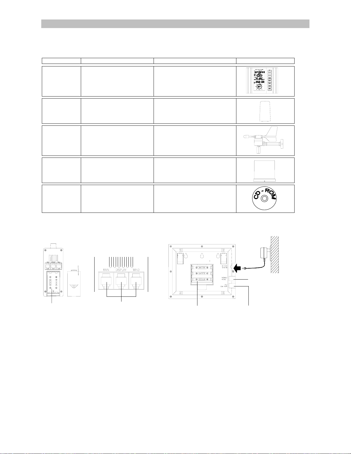
Carefully open and check that the following contents are complete:
Item: Consisting of: Fittings: Illustration:
Base Station
1) Main unit
Thermo-Hygro
Sensor
1) Main unit
2) Rain protection cover
Wind Sensor
1) Main unit with wind vane
2) 32ft cable (already attached the
main unit)
3) Mast holder
Rain Sensor
1) Base and funnel
2) 32ft cable (already attached
the main unit)
‘Heavy
Weather” PC
CD-ROM
(English and German version only)
software
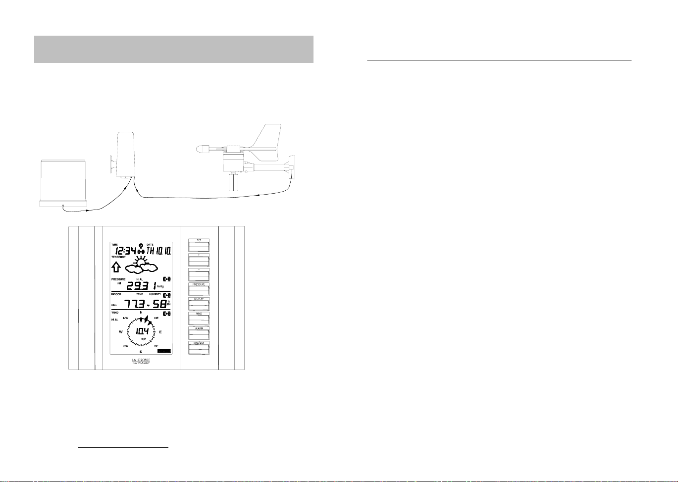
Setting Up:
Important: Operating power is supplied to both the wind and rain sensors b y the thermo-hygro sensor
Thermo-Hygro Sensor
Battery Cover
Battery Compartment
Sensor sockets
Setting up using batteries:
1) Sensors: Pull and remove the protective rain cover to reveal three socket ports and the battery cover. Insert the cables
of the wind and rain sensors in the correctly marked sockets. Slide open the battery compartment and checking the
correct polarity insert 2 x AA 1. 5V batteries and replace the cover and rain cover
2) Base Station: Now open the battery cover at the back of the unit and checking the correct polarity insert 3 x AA 1.5V
batteries and replace the battery cover
Setting up using the AC/DC power adaptor:
1) Sensors: Set up the sensors as described above in Setting up using batteries.
2) Base Station: Using the AC power adaptor (included in this set) plug it into mains supply and connect it to the 6.0V DC
adaptor socket located at the side of the base station.
Performing a function test:
After powering up the units, t he base station has to synchronize to the sensors before the weather data can be received.
The synchronization mode lasts for 15 minutes. Pressing the MIN/MAX key at any time will send the base station into the
WWVB radio controlled time reception mode. Under normal conditions the radio controlled time is usually received within 35 minutes before returning to the normal operation. During the synchronization mode, perform the following function test to
check operation:
1) AD/DC 120V power Adaptor optional use (included)
1) 32ft cable - optional connection to
the base station (included)
2) Wall mounting screws
3) Plastic anchors for screws
1) 2 x U-bolts for mast holder
2) 4 x Washers
3) 4 x Nuts
4) 1 x screw (to secure main unit to the
mast holder)
1) 6.5 ft computer cable for PC
function only - optional use
(included)
Base Station
DC 6.0V
socket
Socket for sensor
Battery compartment
PC COM Port
Page 2

1) Check that the wind-vane and fan of the wind sensor can freely rotate by moving the vane gently and also blowing into
the fan to emulate wind speed and direction
2) Holding the rain sensor in both hands with the longest side facin g you , tilt the unit fr o m side to side and hear the rain
counter flip which emulates rainfall
3) The base station will start to receive the 433MHz data transmitted from the sensors. Data such as rainfall will not be
updated as regularly as the outdoor temperature since it does not rain constantly all the time. Therefore these readings
may take up to two minutes before being shown on the LCD.
4) Now using the DISPLAY key on the base station, toggle between different weather modes on the LCD to check that the
weather readings can be received for the relevant sections, for example outdoor temperature and humidity and etc.
Note: Should any outdoor data not be received from the sensors (when “- - -“ is displayed), check all cables are correctly
inserted and/ or the batteries or AC cord are plugged in, press and hold the PLUS(+) key for 2 seconds to hear a beep and
the base station will synchronize to the sensors transmitting signal. Wind speeds that read zero does not mean reception
failure, it simply means that there was no wind at the time of reading the data.
Mounting the units:
Users must take their surroundings into c onsider ation befor e decidin g which met hod is best sui ted for the m. Connect ion by
cable is advantageous in that data from the sensors to the base station is interference free. Using 433MHz wireless
transmission gives users little restric tion on p laceme nt as th at all un its ca n be p ositione d virtu ally an ywhere to within a 100 ft
radius of the base station. You mus t decide which me thod is best suited to you. For cable connect ing, please ensure that
the 10 meters cable included in this se t m ee ts with your dis tance requirements (see accessories in the main user manual for
adding extension cables).
To change from 433MHz to cable connection (o r vice versa) simp ly connec t (or d i sco nnec t ) the 32f t cab l e from the base
station to the sensor. The base station will automatically detect the connection and read the weather data. If the data
cannot be received then press and hold the PLUS(+) key for 2 seconds to synchronize the base station with the sensor.
Important: Ensure all signals including the radio controlled time can be received and/or all cable distances meet with your
requirements at the point of fixing particularly before you start drilling any mounting holes.
Wind sensor
Secure the main unit to the shaft of the mast holder using the single screw provided with the front of the sensor (marked E)
facing in the East-West direction other wise wind direction will not be accurate. Now fix the entire unit to a suitable ma st
using the 2 two U-bolts, 4 washers and nuts found in this set.
Note: For best results mount the wind sensor onto a mast to all ow the wind to freely trav el from all directions t o enable an
accurate reading (ideal mast size s hould be from Ø6 .3” – Ø1.3”). Ens ure that the 10 meter cable of the wind sensor me ets
your distance requirements.
Rain sensor
The rain sensor should be mounted h orizontally about 2-3ft off from the gr ound in an open area away from trees or o ther
coverings to allow rain to fall naturally for an accurate reading.
Note: For best results ensure the base is horizontal to allow maximum drainage of any collected rain
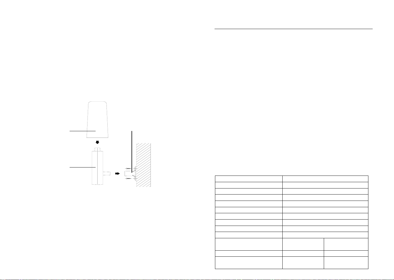
Thermo-hygro Sensor
To wall mount the thermo-hygro sensor , fix the wall holder onto the desire d wall (2 screws are supplied), plug the sens or
firmly into the wall holder and then carefully replace the rain cover back over the thermo-hygro sensor.
Note: After mounting the units, should the weather data not be received then press and hold the PLUS(+ ) key for 2 seconds
to synchronize the base station with the sensor.
Weather station for use with your PC
Use your PC to read the latest weather data collec ted by the weather station. Just simply install the software from the
enclosed CD-ROM onto your PC. For full details see the “Heavy Weather “ PC software instructions in the CD-ROM
(English version only).
System Requirements:
The minimum system requirement for use of “Heavy Weather” PC software is:
• Operating system: Windows 98 or above
• Processor: Pentium 166 MHz or above processor
• RAM: 32MB or above
• Hard-disc: 20MB free space
• CD-ROM drive
Page 3
Operation Manual
Professional Remote Weather Station
This Operation Manual is part of this product and should be kept in a
safe place for future reference. It contains important notes on setup and
operation.
Please see www.heavyweather.info
downloads of the most current software.
WIRELESS
WEATHER STATION
for a complete IM, FAQ and
Table of Contents
Page
1. Introduction………………………………………………..........
2. Intended use……………………………………………………..
Weather Station…………….................................................
System requirements for PC use…………...........................
Features of the base station…………..................................
Features of the wind sensor…………..................................
Features of the rain sensor..................................................
3. Safety Notes........................................................................
4. Packaged contents..............................................................
5. Setting up.............................................................................
6. Operation using cable connection or
wireless 433MHz.................................................................
7. LCD overview ......................................................................
8. Function test........................................................................
9. Mounting..............................................................................
10. Resetting & factory settings.................................................
11. Function description.............................................................
12. Operation keys.....................................................................
13. Basic programming modes..................................................
14. MIN/MAX programming modes............................................
15. Alarm programming modes..................................................
16. Auto-memory for stored values............................................
17. Accessories: extensions cables...........................................
18. Changing batteries...............................................................
19. Problems and interference with operation............................
20. Transmission range.............................................................
21. Cleaning and maintenance..................................................
22. Specifications.......................................................................
Page 4

1. Introduction
Thank you for purchasing this Professional Remote Weather Stat ion.
Designed for everyday use, the weather station will prove to be an
asset of great value for your personal use in the home or office.
Please read this instruction manual thorough ly to fully underst and the
correct operation of your weather station and benefit from its unique
features.
2. Intended Use
Weather Station
The base station measures the indoor environment of its surrounding
area and receives weather data from the fo llowing three out door sensors:
1) Thermo-Hygro Sensor
2) Wind Sensor
3) Rain Sensor
The received data is continuously updated to bring you the latest
weather information on the base station’s LCD. The outdoor thermo-
hygro sensor is the main data communication unit since both t he wind
and rain sensors are connected to the ther mo-hygro sensor for operating power and rely on it to communicate to the base station.
Weather data sent from the thermo-hygro sensor can be done by
wireless 433MHz transmission (up to 100ft in open space) or by cable
connection.
Using the enclosed 6.5ft computer cabl e and CD-ROM, you can install the Heavy Weather software to your PC and access the latest
weather information from your PC and upload up to 175 sets of recorded weather data received by the base station. Recorded data
can be used to generate statistics and chart s onto your spreads heets
(175 sets of data is stored in the base even if the PC is switched
OFF). The software itself does not set any limits as to how many data
sets can be transferred to PC.
This weather station is designed to work easily with your PC, simply
connect and disconnect the PC cable at any time.
System Requirements for PC use:
The minimum system requirement for use of this “Heavy Weather”
software is:
Operating system: Windows 98 or above
Processor: Pentium 166 MHz or above
RAM: 32MB of RAM or above
Hard disk: 20MB free space
CD-ROM drive
For full details on operation and installation of the “Heavy Weather”
software refer to the PC manual in PDF format on the CD-ROM.
Features of the base station:
• Receives and displays the WWVB radio controlled time and date
• Display of extensive weather data, in all cases with programmable
alarm functions for certain weather conditions as well as records of
all minimum and maximum values along with time and date of their
recordings
• Indoor and outdoor temperature displays in degrees Fahrenheit or
Celsius (user selectable)
• Indoor and outdoor relative humidity displays
• Air pressure reading in inHg or hPa, absolute or relative (user select-
able)
• Detailed display of rainfall data in 1 hour, 24 hours, total since last
reset (user selectable in mm or inch)
• Wind speed in mph, km/h, m/s, knots or Beaufort (user selectable)
• Wind direction display with LCD compass as well as numerical (e.g.
225°) and abbreviated characters (e.g. SW)
• Wind chill temperature display
• Dew point temperature display
• Weather forecast display by weather icons (sunny, cloudy, rainy)
• Weather tendency indicator
• Storm warning alarm
• LED back light
• Simultaneous display of all weather data with individual settings by
the user
• COM port for easy connection to your PC
• All the weather data from the base station and up to 175 sets of
weather history data with user adjustable measuring intervals can be
recorded and uploaded to your PC
Page 5
Features of the Thermo-Hygro Sensor
The thermo-hygro sensor measures the outdoor temperatu re and
relative humidity. It also collects the readings from the rain and wind
sensors before transmitting the data to the base station b y wirel ess
433MHz or by the 32ft cable included in this set.
Features of Wind sensor
The wind sensor measures wind speed and wind direction and sends
the data to thermo-hygro sensor, which in turn transmits the data to
the base station. Operating power is taken from the thermo-hygro
sensor using a 32ft cable connection.
Features of Rain sensor
The rain sensor measures the rainfall and sends the data to thermohygro sensor, which in turn transmits the data to the base station.
Operating power is taken from the thermo-hygro sensor by a 32ft
cable connection.
3. Safety Notes
• Damage caused by failure to comply with this instruction manual will
invalidate any guarantee! The manufacturer and supplier will not be
held liable for damages due to failure to comply with this instruction
manual or from data inaccuracies that may occur with this product!
• In case of harm or damage to a person or property caused by im-
proper handling or failure to comply with this instruction manual, the
manufacturer and supplier cannot be held liable.
• For reasons of safety and operation, alterations to this device are
strictly prohibited.
• To operate the weather station, use only supplied adaptor and batter-
ies of the recommended type.
• Do not leave discharged batteries in the device as these may corrode
and release chemicals that may damage the unit.
• Inserting batteries in an incorrect polarity will cause damage to this
product.
• This product is not a toy kept out of the reach of children.
• Do not dispose of new or used batteries in a fire as they may explo-
sion or release dangerous chemicals.
• This product is not to be used for medical purposes or for public
information.
4. Packaged Contents
Before setting up, carefully unpack the co ntents onto a table or flat
surface and check that the following are complete:
Item: Consisting of: Fittings: Illustration:
Base
Station
• Main unit
• AD/DC 120V power
Adaptor - optional use
(included)
ThermoHygro
Sensor
• Main unit
• Rain protection
cover
• 32ft cable - optional
connection to the
base station (included)
• Wall mounting screws
• Plastic anchors for
screws
Wind
Sensor
• Main unit with
wind vane
• 32ft cable
(already attached to the
main unit)
• 2 x U-bolts for mast
holder
• 4 x Washers
• 4 x Nuts
• 1 x screw (to fix main
unit to the mast holder
• Mast holder
Rain
Sensor
• Main unit (base
and funnel)
• 32ft cable
(already attached to the
main unit)
Heavy
weather
PC
software
CD-Rom format
(English and
German language)
• 6.5ft PC cable for PC
connection - optional
use (included)
Page 6
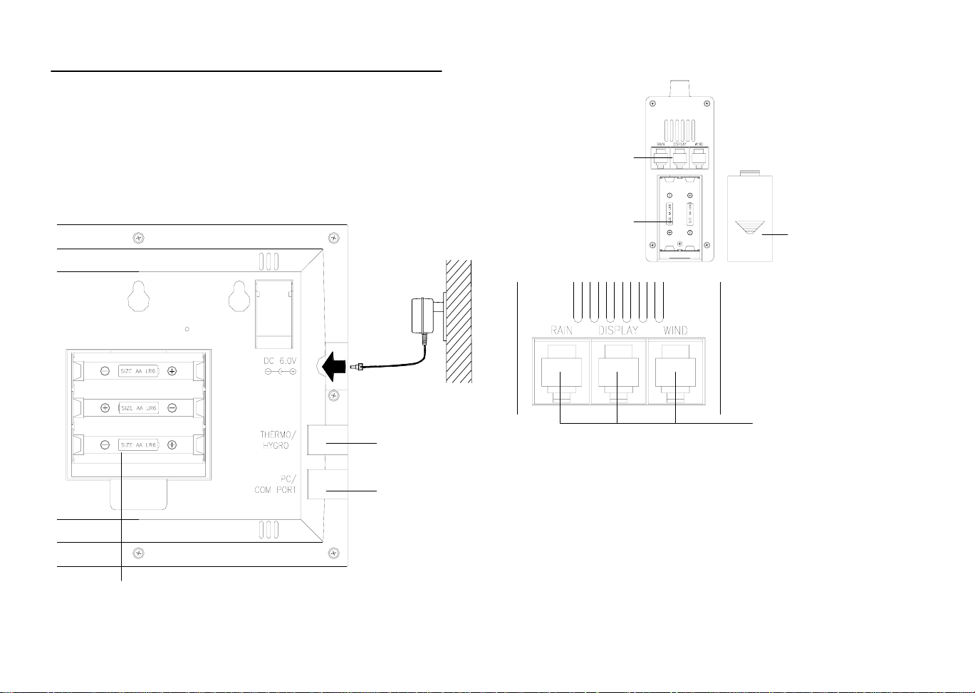
5. Setting up
r
r
First, choose to use the adaptor (included in this set) or batteries for operation. Both these methods allow for operation using wireless 433MHz transmission or cable connection between the base station and the sensors and setting up for both
methods is as follows:
Base Station:
Socket for
Adaptor
Socket for
Thermo-Hygro
Sensor
PC COM
Port
Battery compartment
Setting up using batteries:
Thermo-Hygro Senso
Sensor sockets
Battery
Compartment
Battery Cove
Sensor sockets
Important: To avoid operating problems, please take note of bat-
tery polarity if inserting any batteries
1) Pull away the rain cover of the thermo-hygro sensor to reveal th e
three sockets (for the wind sensor, rain sens or and the base station)
2) Connect the attached cables of wind and rain sensors to the
corresponding sockets of the thermo-hygro sensor by clicking
them into place
3) Open the battery cover of the thermo-hygro sensor located belo w
the three sockets and insert 2 x AA, IEC LR6, 1.5V batter ies and
close the cover
4) Open the bas e station’s battery cover located at the back of the
unit and insert 3 x AA, IEC LR6, 1.5V batteries i nto the battery
compartment and close the battery cover
Page 7

Setting up using the AC adaptor:
1) Power up all the sensors as described in setting up using batteries above
2) Using the AC adaptor (included), plug it into the mains o utlet and
power up the base station by inserting the adaptor jack into the
DC 6.0V socket located on the side of the base station
Every time the thermo-hygro sensor is powered up (f or example after
a change of batteries), a random security code is transmitted an d this
code must be synchronized with the base station to receive weather
data.
When the base station is powered up, a short beep will sound and all
LCD segments will light up for ab out 5 seconds before it enters into a
15 minute learning mode to learn the sensors security code. Af ter the
learning mode (or by pressing the MIN/MAX ke y at an ytime), the base
station will start the WWVB radio controlled time reception.
Note for WWVB Radio Controlled Time:
The time and date display is based on the signal provided by the
highly accurate government operated atomic clock in Ft. Collins,
Colorado. This radio-controlled clock does not only provide for the
weather station’s time and date display but also functions as the time
and date source for all of this weather station’s memory and hist ory
values using time and date information.
LCD backlight:
When using the power adaptor, the LCD backlight is switched on
continuously. Under battery operation, the LCD backlight is switched
on for 15 seconds intervals when any key is pressed.
6. Operation using cable connection or wireless 433MHz
Cable Connection:
Using this method of operation will provide interference free transfer
of the weather data from the sensors to the base station. The data
sending interval from the sensors to the base station will also be more
frequent compared to using 433MHz transmission and will result in
higher power consumption. Therefore batteries will have a shorter life
span for cable connection compared to using 433MHz.
To operate using cable connection, simply use the enclose d 32ft
cable and connect the thermo-hygro sensor to the base station. Once
the connection is detected, the base station will automatically continue reading the data from the sensor.
The user may at any time switch from cable connection to using
433MHz (or vice versa) by simply disconnecting (or connecting) the
cable from the base station to the sensor. When the base station
detects no cable connection to the sensors the base station will automatically change to using 433 MHz for reception of the weather data
from the sensors.
The data receiving intervals are as follows:
-Using cable connection data is updated every 8 seconds.
-Using wireless 433 MHz data is updated from 16 to 128 second
intervals depending on wind speed and rain activity.
Using the AC adaptor to operate the base station will also supply
power to the sensor if the cable is connected to it. Batteries used for
433MHz transmission may be left in the sensor when using cable
connection for power back up in case of AC power failure. A loss of
power would desynchronize the base station and the sensor and no
weather data will be received. To Synchronize the units so that the
weather data can be received, press and hold the PLUS (+) key for 2
seconds. However in general, batteries that will not be used for long
periods should be removed to avoid leakage.
Wireless 433MHz transmission:
Using 433MHz wireless transmission of weather data from the sensor
to the base station will provide users greater freedom as to where
units can be positioned without the need to be restricted b y cable.
Note:
If no outdoor weather data is displayed or the sign al to the sensors is
lost during setting up, mounting, changing of batteries to the sensor or
plugging or unplugging cables, simply press and hold the PLUS (+)
key for 2 seconds and a short beep will sound to synchronize the
base station to sensors. Without being synchronized, weather data
will not be received.
Page 8
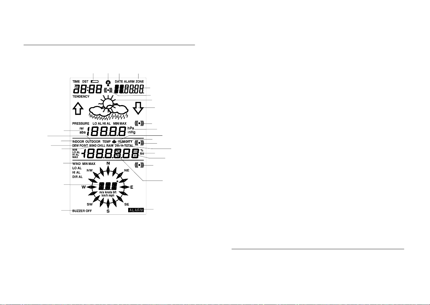
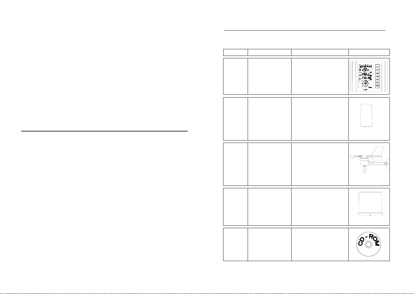
7. LCD Overview
The following illustration shows the full segments of the LCD for
description purposes only and will not appear like this during
normal operation and use.
1. Low battery indicator
2. WWVB radio controlled time icon
3. Date display
4. Time zone display
5. Date, seconds, alarm time and time
zone
6. Alarm icon
7. Weather forecast icons
8. Weather tendency indicator
9. Pressure alarm display
10. hPa/inHg air pressure unit
11. Pressure units (relative or absolute)
12. 433MHz reception icon
13. Rainfall display
14. Indoor, outdoor, humidity, dew point,
wind chill, rainfall alarm icon
19
21
11
20
22
24
25
26
1
3
2
15. 24h, 1h or total hour display
16. Humidity display as RH%
17. Rainfall units (inch or mm)
18. Temperature display units (ºC or ºF)
19. Outdoor temperature/humidity display
20. Indoor temperature/humidity display
21. Dew point temperature display
22. Wind chill temperature display
23. Wind alarm icon
24. Wind information for Min/Max speed
25. Wind direction and speed (m/s, knots,
26. Alarm buzzer ON/OFF icon
27. General alarm icon
4
5
6
7
8
9
10
12
13
14
15
16
17
23
18
27
and wind speed low, high, direction
alarm
Beaufort, km/h or mph) display
8. Function test:
Once the weather station is powered up, perform a function test b y
checking that the weather data is received. To do this, press the
DISPLAY, PRESSURE or WIND keys to toggle through the relevant
LCD sections:
1) Indoor temperature and humidity
2) Outdoor temperature and humidity
3) Outdoor wind chill
4) Dew point
5) Rainfall 24 hour
6) Rainfall 1hour
7) Rainfall Total
8) Relative and absolute pressure
9) Wind speed, wind direction and wind direction in degrees
If any readings cannot be received from the sensors, lines (- - -) will
be displayed in the respective weather sections of the LCD. In this
case, check that all cables are correctly inserted into the correct
sockets and/or check the batteries in the outdoor t hermo/hygro sensor and press and hold the PLUS (+) key for 2 seco nds and a short
beep will sound to synchronize the base station to t he sensors otherwise no weather data will be received.
Some weather readings such as wind speed and direction may not
appear immediately on the LCD if the wind-fan or vane of the wind
sensor is moved. This is due to the set reading time intervals for t he
wind readings. However the current wind speed or direction will be
displayed once the time reading interval is reached. For rainfall, the
interval readings may take up to 2 minutes before the data is displayed on the LCD.
9. Mounting
Important Note
Prior to drilling mounting holes and permanently affixing any of the
units, please ensure the following points are considered:
• Cable lengths of the units meet with your distance requirements
at the point of fixing
Page 9

• Signals from the sensors can be received by the base station at
points of mounting
• Radio controlled time signal can be received at the point of
mounting
NOTE: The WWVB receiver is located in the base station.
Base Station
With two foldable legs at the back of the unit, the base station can be
placed onto any flat surface or wall mounted at the desired location by
the hanging holes also at the back of the un it. It is important t o check
that the 433MHz (if using wireless connection) and the WWVB radio
controlled time signal can be received before permanently mounting
any of the units. Should the base station not display the 433MHz
weather data from the sensors or the radio controlled time from the
desired location, then relocate the units. Once the signals are received, the system can be affixed. Also if you have sele cted to use
cable connection, ensure that distances can reach all desired locations before affixing any unit permanent ly
NOTE: For reception of WWVB time/date signal, do not mount
the base station closer than 5 feet from a computer, florescent
lights or other electrical appliances. Do not mount the base
station on a wall that has metal heat/AC ductwork in the wall
behind the base station. For best WWVB reception place the
base station near a window facing Colorado. WWVB reception
will be obtained easiest in the nighttime hours when the
WWVB signal is strongest.
Mounting the Wind Sensor onto a mast
Wind-vane
Wind-fan
Firstly, check that the wind-fan and the wind-vane can rotate freely
before fixing the unit. For correct and accurate readings it is important to mount the sensor so that the front ( marked E) is pointing in
East-West direction. The wind sensor should now be mounted using
the screw provided onto a mast to allow the wind t o travel around the
sensor unhindered from all directions (ideal mast size should be from
Ø.63” – Ø1.3”).
Once the wind sensor is fixed onto the mast, connect the cable to th e
corresponding thermo-hygro sensor socket so that operating power
supply can be received and data can be tra nsmitted to the base station.
Mounting the Rain Sensor
Base portion
For accurate results, the rain sensor should be securely mounted
onto a horizontal surface about 2-3ft above the ground and in an open
area away from trees or other coverings where rainfall may be reduced causing inaccurate readings.
When securing into place, check that rain excess will not collect and
store at the base of the unit but can flow out between the base an d
the mounting surface (test by pouring clean water).
Page 10
After mounting the rain sensor, connect the cable t o the ther mo-hygro
sensor at the corresponding socket so power supply can be receiv ed
and data be transmitted to the base station
The rain sensor is now operable. For testing purposes, very slowly
pour a small amount of clean water into the rain sensor fu nnel. The
water will act as rainfall and will be received and displayed at the
base station after about 2 minutes d ela y i.e. when t he read ing interval
is reached (to clear this testing data on t he base station, refer to the
section “MIN/MAX Mode” below).
Mounting the thermo-hygro Sensor
Rain Cover
Wall Bracket
Main Unit
An ideal mounting place for the thermo-hygro sensor would be the
outer wall beneath the extension of a roof, as this will protect the
sensor from direct sunlight and other extreme weather condit ions.
To wall mount, use the 2 screws to affix the wall bracket to the desired wall, plug in the thermo-hygro sensor to the brack et and secure
both parts by the use of the supplied scre w and ensure that the cables from the wind and rain sensors are correctl y plugged in otherwise data transmission errors could occur.
NOTE: For best 433 MHz reception mount the thermo-hygro sensor on an outside wall near the location of th e base station.
10. Resetting & factory settings:
As previously mentioned, in the event of a power reset to the sensor
(for example a change of batteries), the base st ation has to synchronize to the sensor again otherwise no weat her data will be received.
To do this, simply press and hold the PLUS (+) ke y for 2 seconds and
a short beep will sound to synchronize the base station to the s ensor.
When the units are synchronized, the dat a will be received ag ain and
the base station will return to normal operation mode.
Do not remove batteries or unplug the AC adaptor of the base station
otherwise all 175 sets of recorde d weather history data for transferring to the PC will be lost (for full deta ils of PC use, please see PC
user manual in the enclosed Heavy Weather CD-ROM).
However if you wish to make a full reset of the base station and retur n
to the original factory settings, simultaneously press and hold the
PRESSURE and WIND keys for about 5 seconds. The b ase station
will beep once and the entire LCD will light up for 5 seconds and go
back to the original factory sett ings. This process with cle ar all previous user defined values and all weather history recordings.
Factory default settings:
The following table shows the factory default values of the weather
station:
Matter: Default Setting:
Time 0:00
Date 01.01.2001
Time zone -5 ET
Alarm time 12:00 am
Relative air pressure 29.91 inHg
Weather-picture threshold 0.09 inHg
LCD contrast level 5 (1-8 levels)
Rainfall per impulse 0.0204 inches
Storm alarm 0.09 inHg
Relative air pressure
alarm
28.34 inHg
(low)
30.71 inHg
(high)
Indoor temperature alarm 50ºF (low) 86ºF (high)
Outdoor temperature
32ºF (low) 104ºF (high)
alarm
Page 11
Indoor humidity alarm 35%RH (low) 65%RH (high)
Outdoor humidity alarm 45%RH (low) 70%RH (high)
Wind chill alarm 50ºF (low) 86ºF (high)
Dew point alarm 32ºF (low) 68ºC (high)
Rainfall 24h alarm 1.96 inches
Rainfall 1h alarm 0.03 inches
Wind Speed 1.0 mph (low) 62 mph (high)
Wind direction alarm None set
Note:
All alarm default values are deactivate d at the start up and any alarm
must be activated by the user otherwise it will not sound.
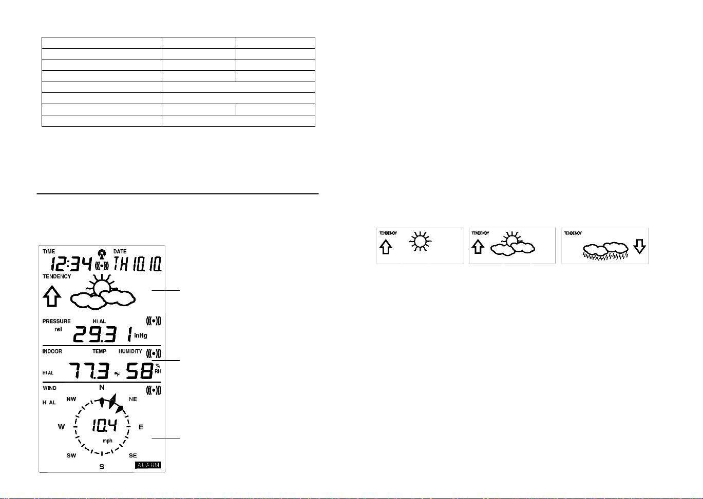
11. Function Description of the Weather Station
After setting up, the following data will be displayed in different sections on the LCD. If this is not the case please observe t he notes on
“Interferences” below.
LCD Section 1:
Time, date, seconds, time zone,
weather forecasting icons with
tendency arrows, air pressure,
and respective alarms sections
LCD Section 2:
Indoor and outdoor temperature and
relative humidity, wind chill, dew
point, rainfall, and respective alarms
sections
LCD Section 3:
Wind direction, wind speed, and respective alarms sections
Time & Date (LCD Section 1)
If the WWVB icon (icon 2) is ON and not flashing, it means that the
WWVB radio-controlled time and date are has been received. Press
the PLUS (+) key to change the format of date display between
date/month/year, weekday/date/month, seconds, alarm set time and
time zone.
Weather forecasting (LCD Section 1)
The three weather icons Sunny, Cloudy and Rainy represent the
weather forecasting. There are also two weather tendenc y indicators
to show the air pressure tendency either side of the weather icons.
Sunny Rainy Cloudy
Notes to hPa sensitivity setting for weather forecasting:
The hPa (Hekto-Pascal) pressure sensitivity can be set to suit the
user’s requirement for weather forecasting from 6 inHg, 9 inHg to 12
inHg (see Basic Programming below). For areas that exp erience
frequent changes in air pressure (which does not necessarily reflect a
change in the weather) requires a higher inHg setting compared t o an
area where the air pressure is stagnant. For example if 6 inHg is
selected, then there must be a fall or rise in air pressure of at least 6
inHg before the weather station will register this as a change in
weather.
Air Pressure (LCD Section 1)
The air pressure reading is displayed here. Press the PRESSURE
key to toggle between relative and absolute air pressure displays.
Notes to Absolute and Relative Air Pressure:
Absolute air pressure provides the display of the true measured air
pressure of the current time and location. This is not programmable
and the absolute air pressure range of the weather station is from
Page 12

8.85 inHg to 32.45 inHg (standard air pressure at an altit ude of
30,000ft is around 8.85 inHg).
Relative air pressure is the one value that is calculated back to sea
level from the local absolute air pressure and can thus be taken as a
reference for weather condition and weather development for the
entire country. It can be programmed to represent your l ocal surroundings. Since the relative air pressure is also the one value given
by various newspapers, TV and radio broadcasting stations in their
daily weather forecasts for their respective locations, users can set
the relative air pressure of the weather station to this value to represent readings your their area (see Basic Programming Modes below).
Weather Data (LCD Section 2)
Indoor temperature and humidity are displayed simu ltaneously in this
section. Use the DISPLAY key to toggle through the displays f or other
weather information:
- Outdoor temperature/humidity
- Outdoor wind chill
- Outdoor dew point
- Rainfall 24h
- Rainfall 1h
- Rainfall total.
Notes to Dewpoint and Windchill:
Air can at a certain temperature only carry a cert ain amount of water
(water vapor), which also increases and decreases with temperat ure.
If the air temperature decreases below the dewpoint (saturation
point), the excessive water vapor will condense and fall ou t in form of
dew, fog or rain. At a temperature of e.g. 5 9°F and a relativ e humidity
of 50% the dewpoint will be about 41°F, at 80% humidity about
53.6°F. At a relative humidity of 100% satur ation is reached, i.e. the
dewpoint is 59°F. At a dewpoint below freezing the fallout will become
frost or snow.
Windchill has been introduced for battle planning during World War I I.
It represents not the real measured but the temperature a person
feels in open area under the influence of wind and col d. Windchill is
laid out in tables for various temperatures and wind speeds. At an
outdoor temperature of e.g. 46.4°F and calm winds a per son moving
at a speed of 13 mph will already feel a windchill temperature of 32°F.
Wind Data (LCD Section 3)
The current wind direction will be displayed on the LCD compass on
the wind section. Press the WIND key to toggle between wind direction as numerical (e.g. 225°) and abbreviated characters (e.g. SW) as
well as numerical wind speed display inside the compass circle.
Page 13

12. Operation keys
The base station has 8 keys for easy operat ion. Please refer to the
following table for use and function of each ke y: Further descriptions
of the key functions with regard to th eir immediate range of application can be found in the Programming modes:
SET - key
- In normal mode to enter the manual basic
programming mode
- In basic programming mode to select the
following setting modes:
- LCD contrast setting
- Manual time setting (hours/minutes)
- 12/24 time format display
- Calendar setting (year/month/date)
- Time zone setting
- °C/°F temperature setting
- Wind speed unit setting
- Rainfall unit setting
- Pressure unit setting
- Relative air pressure setting
- Weather picture threshold setting
- Storm warning setting
- Audible storm alarm setting
- In setting modes confirmation of the selected values
- In alarm modes alarm ON/OFF
- In alarm mode to enter programming of
alarm values (long pressing)
- To exit MIN/MAX modes
PRESSURE - key
- Toggle between Absolute and Relative air
pressure displays
DISPLAY - key
- Toggle between the following current/
maximum/ minimum display modes:
- Indoor temperature and humidity
- Outdoor temperature and humidity
- Outdoor wind chill
- Outdoor dew point
- Rainfall (24h, 1h, total)
WIND - key
To toggle between the following settings:
- Wind speed
- Wind direction
- Wind direction display in degrees
ALARM - key
MIN/MAX - key
PLUS (+) – key
MINUS (-) – key
- In normal mode to enter the alarm programming mode
- In alarm programming mode to select the
following setting modes:
- Time alarm setting
- Indoor temperature alarm (high & low)
- Outdoor temperature alarm (high & low)
- Indoor humidity alarm (high & low)
- Outdoor humidity alarm (high & low)
- Outdoor wind chill alarm (high & low)
- Outdoor dew point alarm (high & low)
- Rainfall alarm (24h, 1h)
- Pressure alarm (high & low)
- Wind speed alarm (high & low)
- Wind direction alarm
- In setting modes confirmation of the selected values
- To exit MIN/MAX modes
- To reset general alarm symbol
- In normal display mode to toggle between
display of MIN/MAX values
- To toggle between MIN/MAX values in
MIN/MAX mode
- To exit any programming mode
- In normal display mode to toggle betw een
format of date display, seconds, time alarm
and time zone
- To increase the values in the setting
modes
- To exit MIN/MAX modes
- In normal display mode to re-enter data
learning mode (long pressing for 2 seconds)
- In normal display mode to enable/disab le
the buzzer alarm (long pressing)
- To decrease the values in the setting
modes
- In basic programming mode audible storm
alarm ON/OFF
- To snooze the alarms off 24 hours when
the alarm is sounding
- In MIN/MAX modes to reset recorded
values and recorded dates and times
Page 14

13. Basic Programming Modes
Manual Setting modes
The manual setting mode allows the user to change several basic
settings, which is done by accessing one mode aft er the other simply
by pressing the SET key. After the final mode, or if no key is pressed
for 30 seconds, the manual setting returns to the normal display
mode.
The manual setting takes the user through the follo wing modes:
1. 8 level LCD contrast setting (default level 5)
2. Manual time setting (hours/minutes)
3. 12/24h time display select (default 12 hours)
4. Calendar setting (year/month/date)
5. Time zone set ting from 0 to +12 hrs, -1, -2, -3, AT -4, ET -5,
CT -6, MT -7, PT -8, AL -9, HA -10, -11, -12 (default ET -5)
6. Temperature display unit degree Celsius or Fahren heit (default degree Fahrenheit)
7. Wind speed display units in m/s, km/h, mph, Beaufort, knots
(default setting mph)
8. Rainfall display in mm or inch (default setting inch)
9. Air pressure display in hPa or inHg (default setting inHg)
10. Relative air pr essure setting from 27.10 inHg – 31.90 inHg
(default 29.98 inHg)
11. Weather forecast sensitivity setting 6, 9, 12 inHg (default
setting 9 inHg)
12. Storm warning sensitivity setting 9, 12, 15, 18, 21, 24, 29
inHg (default 9 inHg)
13. Audible storm alarm On/OFF (default ON)
To change any of the above values, once your are in the setting
mode, use the PLUS (+) or MINUS (-) keys to select the values followed by the SET key to enter t he next set ting. Cont inue t o pr ess th e
SET key to toggle through the setting mode until the LCD ret urns to
the normal display mode or press the MIN/MAX key at any time to
exit.
Note!
Keeping the PLUS (+) or MINUS (-) key depressed when setting
certain units in the manual setting mode will increase/decre ase digits
in greater steps.
Manual time setting
The base station will continue to scan for the radio controlled time
signal from 12am-6 am (1am-6pm summer time) each day despite it
being manually set. During reception attempts t he WWVB tower icon
will flash.
• If reception has been unsuccessful, then the WWVB to wer
icon will not appear but reception will still b e attempted the
following hour within the time frame
•
If reception has been successful, the received time a nd date
will overwrite the manually set time and date and n o further
reception is attempted until the following day
14. MIN/MAX Programming Modes
MIN/MAX display Mode
The MIN/MAX Mode provides the user with information about the
MIN/MAX values of all weather data together with the t ime and date
at which these values were recorded.
Entering each MIN/MAX mode
In the normal display mode for e.g. the indoor temper ature and humidity, press MIN/MAX key to togg le the display between the maximum, minimum and current records. While the maximum or minimum
values are shown press the DISPLAY key on ce to show the time an d
date that value was received. Now press th e MIN/MAX key to toggle
from the minimum and maximum readings and the time and dates the
records were received are also shown. Still in the MIN/MAX mode
(where the time and date for a value are sho wn), press the DISPLAY
key to move through each respective unit as follows:
• Indoor temperature (max or min with time and date)
• Indoor humidity (max or min with time and date)
• Outdoor temperature (max or min with time and date)
• Outdoor humidity (max or min with time and date)
• Outdoor wind chill (max or min with time and date)
• Outdoor dew point (max or min with time and date)
• Rainfall 24 hours (max or min with time and date)
• Rainfall 1 hour (max or min with time and date)
•
Rainfall total (max only with time and date)
Page 15

When in any of the above modes, press the MIN/MAX key to t oggle
between the maximum or minimum values of those records and their
respective time and dates will also be shown.
For the wind and pressure minimum and maximum readings, the
same would apply except that the WIND or PRESSURE keys would
be used instead of the DISPLAY KEY.
Exiting the MIN/MAX modes
If the maximum and minimum modes with times and dates are displayed, press the PLUS (+) key twice to return the normal display
mode.
Resetting the MIN/MAX records
While in the minimum or maximum mode, the time and d ates are also
displayed along with the recorded values. If the MINUS (-) key is
pressed while any of these values ar e displayed, that particular minimum or maximum record will be reset to current reading together with
the current time and date with the exception of the following:
The first case is Rainfall Total, which has neith er maximum nor
minimum records since it will show only the total rainfall. Pressing
the MINUS (-) key will reset the rainfall total value to zero and the
time recording to current time.
The second case is Rainfall 24h or 1h, which records maximum
rain count only for these respective times. Pressing the MINUS () key in either of these two modes will reset the rain c ount to the
current rain count and time and date.
The third case is wind speed, which will only reset t he recorded
time to current time when the MINUS (-) key is pressed.
15. Alarm Programming Modes
Alarm Modes
As well as the normal time alarm, this feat ure will allo w users to set a
range of specific alarms to meet specific weather and temperature
conditions set by the user. The weather station allo ws for the following 13 alarms modes to be set:
1. Time alarm
2. Indoor temperature high alarm and low alarm
3. Outdoor temperature high alarm and low alarm
4. Indoor humidity high alarm and low alarm
5. Outdoor humidity high alarm and low alarm
6. Wind chill high alarm and low alarm
7. Dew point alarm high alarm and low alarm
8. Rainfall 24h alarm
9. Rainfall 1h alarm
10. Pressure high alarm and low alarm
11. Wind speed high alarm and low alarm
12. Wind direction alarm
13. Storm warning alarm
Setting Alarms:
For alarm setting, press the ALARM key once while in normal operation mode to enter the normal alarm time and by further pressing the
ALARM key will toggle through each of the alarm modes:
Note:
The alarm icon will automatically appear upon pressing the SET
key to tell the user the alarm is activated. Further pressing the
SET key will deactivate/reactivate the alarm.
Time alarm setting
1) Press the ALARM key to enter the normal time alarm
2) Press and hold the SET key to enter the alar m hour time set
mode (the hour digits will flash) and set the desired hour by using
the PLUS (+) or MINUS (-) keys
3) Press the SET key to enter the alarm minute time set mode (the
minutes digits will flash) and set the desired minutes using the
PLUS (+) or MINUS (-) keys
4) Press ALARM key to confirm followed by the MIN/MAX key to
return to the normal display mode.
Indoor temperature high alarm and low alarm setting
1) Press the ALARM key to enter the normal time alarm
2) Press the ALARM key again to enter indoor temperature high
alarm set mode
3) Press and hold the SET key to enter the indoor temperature high
setting values (digits will start flashing) and set the desired indoor
temperature high by using the PLUS (+) or MINUS (-) keys
Page 16

4) Press ALARM key to confirm and press the MIN/MAX key to return to the normal display mode or press the ALARM once more to
toggle to the indoor temperature low alarm set mode.
5) Press and hold the SET key to enter the indoor temperature low
setting values (temperature digits will start flashing) and set the
desired indoor temperature low by using the PLUS (+) or MINUS () keys
6) Press ALARM key to confirm and press the MIN/MAX key to return the normal display mode or press the ALARM once more to
toggle to another alarm setting mode.
Outdoor temperature high alarm and low alarm setting
1) Press the ALARM key to enter the normal time alarm
2) Continue to press the ALARM key until you reach the outdoor
temperature high alarm set mode
3) Press and hold the SET key to enter the outdoor temperature high
setting values (temperature digits will start flashing) and set the
desired outdoor temperature high by using the PLUS (+) or MI NUS (-) keys
4) Press ALARM key to confirm and press the MIN/MAX key to return to the normal display mode or press the ALARM once more to
toggle to the outdoor temperature low alarm set mode.
5) Press and hold the SET key to enter the outdoor temperature low
setting values (digits will start flashing) and set the desired outdoor
temperature low by using the PLUS (+) or MINUS (-) keys
6) Press ALARM key to confirm and press the MIN/MAX key to return the normal display mode or press the ALARM once more to
toggle to another alarm setting mode.
Indoor humidity high alarm and low alarm setting
1) Press the ALARM key to enter the normal time alarm
2) Continue to press the ALARM key until you reach the indoor humidity high alarm set mode
3) Press and hold the SET key to enter the indoor humidity high
setting values (% digits will start flashing) and set the desired indoor humidity high by using the PLUS (+) or MINUS (-) keys
4) Press ALARM key to confirm and press the MIN/MAX key to return to the normal display mode or press the ALARM once more to
toggle to the indoor humidity low alarm set mode.
5) Press and hold the SET key to enter the indoor humidity low setting values (digits will start flashing) and set the desired indoor
humidity low by using the PLUS (+) or MINUS (-) keys
6) Press ALARM key to confirm and press the MIN/MAX key to return the normal display mode or press the ALARM once more to
toggle to another alarm setting mode.
Outdoor humidity high alarm and low alarm setting
1) Press the ALARM key to enter the normal time alarm
2) Continue to press the ALARM key until you reach the outdoor
humidity high alarm set mode
3) Press and hold the SET key to enter the outdoor humidity high
setting values (digits will start flashing) and set the desired outdoor
humidity high by using the PLUS (+) or MINUS (-) keys
4) Press ALARM key to confirm and press the MIN/MAX key to return to the normal display mode or press the ALARM key once
more to toggle to the outdoor humidity low alarm set mode.
5) Press and hold the SET key to enter the outdoor humidity low
setting values (digits will start flashing) and set the desired outdoor
humidity low by using the PLUS (+) or MINUS (-) keys
6) Press ALARM key to confirm and press the MIN/MAX key to return the normal display mode or press the ALARM once more to
toggle to the to enter another alarm setting mode.
Wind chill high alarm and low alarm setting
1) Press the ALARM key to enter the normal time alarm
2) Continue to press the ALARM key until you reach the wind chill
high alarm set mode
3) Press and hold the SET key to enter the wind chill high setting
values (digits will start flashing) and set the desired wind chill high
by using the PLUS (+) or MINUS (-) keys
4) Press ALARM key to confirm and press the MIN/MAX key to return to the normal display mode or press the ALARM key once
more to toggle to the wind chill low alarm set mode.
5) Press and hold the SET key to enter the wind chill low setting
values (digits will start flashing) and set the desired wind chill low
by using the PLUS (+) or MINUS (-) keys
6) Press ALARM key to confirm and press the MIN/MAX key to return the normal display mode or press the ALARM once more to
toggle to another alarm setting mode.
Page 17

Dew point alarm high alarm and low alarm setting
1) Press the ALARM key to enter the normal time alarm
2) Continue to press the ALARM key until you reach the dew point
high alarm set mode
3) Press and hold the SET key to enter the dew point setting values
(digits will start flashing) and set the desired dew point high by using the PLUS (+) or MINUS (-) keys
4) Press ALARM key to confirm and press the MIN/MAX key to return to the normal display mode or press the ALARM key once
more to toggle to the dew point low alarm set mode.
5) Press and hold the SET key to enter the dew point low setting
values (digits will start flashing) and set the desired de w point low
by using the PLUS (+) or MINUS (-) keys
6) Press ALARM key to confirm and press the MIN/MAX key to return the normal display mode or press the ALARM once more to
toggle to another alarm setting mode.
Rainfall 24h alarm setting
1) Press the ALARM key to enter the normal time alarm
2) Continue to press the ALARM key until you reach the rain 24 ho ur
alarm set mode
3) Press and hold the SET key to enter the rain setting values (digits
will start flashing) and set the desired rain values by using the
PLUS (+) or MINUS (-) keys
4) Press ALARM key to confirm and press the MIN/MAX key to return to the normal display mode or press the ALARM key once
more to toggle to another alarm setting mode.
Rainfall 1h alarm setting
1) Press the ALARM key to enter the normal time alarm
2) Continue to press the ALARM key until you reach the rain 1 hour
alarm set mode
3) Press and hold the SET key to enter the rain setting values (digits
will start flashing) and set the desired rain values by using the
PLUS (+) or MINUS (-) keys
4) Press ALARM key to confirm and press the MIN/MAX key to return to the normal display mode or press the ALARM key once
more to another alarm setting mode.
Pressure high alarm and low alarm setting
1) Press the ALARM key to enter the normal time alarm
2) Continue to press the ALARM key until you reach the pressure
high alarm set mode
3) Press and hold the SET key to enter the pressure setting values
(digits will start flashing) and set the desired pressure high by using the PLUS (+) or MINUS (-) keys
4) Press ALARM key to confirm and press the MIN/MAX key to return to the normal display mode or press the ALARM key once
more to toggle to the pressure low alarm set mode.
5) Press and hold the SET key to enter the pressure low setting
values (digits will start flashing) and set the desired pressure low
by using the PLUS (+) or MINUS (-) keys
6) Press ALARM key to confirm and press the MIN/MAX key to return to the normal display mode or press the ALARM once more to
toggle to another alarm setting mode.
Wind speed high alarm and low alarm setting
1) Press the ALARM key to enter the normal time alarm
2) Continue to press the ALARM key until you reach the wind speed
high alarm set mode
3) Press and hold the SET key to enter the wind speed setting values
(digits will start flashing) and set the desired wind speed high by
using the PLUS (+) or MINUS (-) keys
4) Press ALARM key to confirm and press the MIN/MAX key to return to the normal display mode or press the ALARM key once
more to toggle to the wind speed low alarm set mode.
5) Press and hold the SET key to enter the wind speed low setting
values (digits will start flashing) and set the desired pressure low
by using the PLUS (+) or MINUS (-) keys
6) Press ALARM key to confirm and press the MIN/MAX key to return the normal display mode or press the ALARM once more to
toggle to another alarm setting mode.
Wind direction alarm setting
1) Press the ALARM key to enter the normal time alarm
2) Continue to press the ALARM key until you reach the wind direction alarm set mode
3) Press and hold the SET key to enter the wind direction setting
values.
Page 18

4) Using the PLUS (+) or MINUS (-) keys select the desired wind
direction and use the SET key to confirm or cancel each direction
input
5) Press ALARM key to confirm and press the MIN/MAX key to return the normal display mode or press the ALARM once more to
toggle to another alarm setting mode.
Storm warning alarm setting
Unlike the other weather alarms, the storm warning alarm is set by
entering the main manual setting mode as follo ws:
10) Press the SET key to enter the manu al setting mode
11) Continue to press the SET key until the Storm warning icon
flashes (tendency arrow flashing downwards with the pressure
values flashing)
12) Set the desired inHg pressure value (9, 12, 15, 18, 21, 24, 27
inHg) using the PLUS (+) or MINUS (-) keys
13) Press the MIN/MAX key to confirm and return to the normal display.
Storm warning alarm ON/OFF
After storm warning alarm setting, the next mode to appear aft er
pressing the SET key is the storm warning ON/OFF. Use the PLUS
(+) or MINUS (-) key to change the status to AON or AOFF. Default
setting is ON:
Should the air pressure drop equal or below the pre-set inHg value
within the last 6 hour period, then the downward tendency arrow will
flash as an indication of possible storm. The base station will take
hourly measurements as a point of reference. The storm-warning
indicator will stop flashing once the air pressure becomes more st able.
Master Alarm – BUZZER OFF
The time and all the weather alarms may have buzzer sound set to
OFF by holding the MINUS (-) key down for about 3 seconds in normal display mode and the BUZZER OFF icon appears on the bottom
left of the LCD. When the BUZZER OFF is displayed, the ti me and all
other weather alarms when activated will only flash but not sound
regardless if that particular alarm has been set to the ON. To deactivate the BUZZER OFF, press the MINUS (-) key once more.
General Alarm Icon
The general alarm icon on the bottom right corner of the LCD will
appear when any weather alarm is activated to sho w the user that a
set weather condition has been reached. The activated alarm can be
determined by checking the set alarm values against the MIN/MAX
values reached. To deactivate the general weather alarm icon, press
the ALARM key.
Important
When entering the alarm set mode for a spec ific weather or temper ature condition, the corresponding alarm is automaticall y enabled (ON)
when the SET key is pressed, regardless of its previous setting and
the alarm value will flash to indicate t hat it has bee n activated. Press
the ALARM key to confirm the setting and continue pressing the
ALARM key to toggle through each alarm mode until it returns to the
normal display mode or press the MIN/MAX key at any time to exit the
alarm setting modes.
When a set weather alarm condition has been activated, that particular alarm will sound and flash for approximately 2 minutes but will
continue to flash until weather conditions have become more steady.
Weather Alarms
The weather alarms are settable for when certain weather conditions
are met according to the users requirements. For example , the user
can set the thresholds for the outdoor temperature to +86°F (high)
and 14°F (low), while only enabling the high alarm and dis abling the
low alarm (i.e. temperatures <-14°F won’t trigger alarm, but temperatures >+86°F will).
Alarm setting Minimum Maximum
Storm threshold 0.09 inHg 0.27 inHg
Relative Air Pressure 27.10 inHg 31.89 inHg
Outdoor Temperature -21.8°F +157.8°F
Indoor Temperature 14.1°F. No alarm will
sound if the minimum
indoor temperature
alarm is set below this
value.
Humidity (all) 20% RH 95% RH
Rainfall 24h 0.0 inch 39.37 inch
Rainfall 1h 0.0 inch 39.37 inch
Wind 0.0 mph 111.8 mph
+139.8°F
Page 19
Hysteresis
To compensate for fluctuation of the measured data, which may
cause the weather alarm to sound constantl y if the measure d reading
is close to user set level, a hysteresis function has be en implemente d
for each weather alarm. For example, if the hig h temperature alarm is
set to +77°F and the current value moves to +78°F, the al arm will be
activated (if it has been enabled). Now when the temperature drops to
+76°F or below and thereafter agai n increases to beyond +77°F, the
data will be blinking, but no alarm will be activated. It has to drop t o
below +75.2°F (with a pre-set hysteresis of 1.8°F) so that the alarm
can be produced again. Hysteresis values for the various weather
data types are given in the following table:
Weather data Hysteresis
Temperature 1.8°F
Humidity 3% RH
Air pressure 0.0295 inHg
Rainfall 24h 0.1968 inch
Rainfall 1h 0.01968 inch
Wind 3.1 mph
16. Auto memory for stored values
The base station has a memory back up system, which is used to
memorize user-defined settings for when the batt eries ar e chan ged or
if a power failure occurs. User defined units a re aut om atical l y upd ated
each time these are changed. The base station will memorize the
following user defined units:
• Time zone
• 12/24h time display mode
• Unit settings (temperature, pressure, rainfall, wind)
• Air pressure off s et for calculation of relative air pressure
• Weather picture threshold
• Storm warning threshold
• LCD contrast
• Alarm time
• Weather Alarm thresholds
• State of alarms (enabled/disabled)
• Rainfall total value and reset time/date
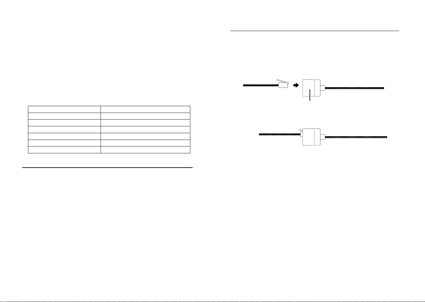
17. Accessories: adding cable extensions
For your convenience, additional telephone cables to increase the
connection distance between each of the units may be purchased
from any reputable hardware store. Simply add these to the current
cables to extend your cable connection distan ce.
Telephone Extension Cables
When securing the cables during mounting, ensure that base station
can receive the weather data since increasing the cables lengt hs may
also increase levels of interference and result with reception difficulties. Interference levels will greatl y depend on the surrounding area
for example setting up on or near metal piping may considerably
reduce reception.
For best results, do not to add more than 32ft of extension cabl e from
item to item onto the existing cable lengths as this may reduce reception levels. Again, reception and interferen ce levels will greatly depend on the surrounding environment at your point of mounting.
Note:
It is important to keep all the connecte d extension heads away from
rain, moisture and other extreme weather conditi ons as exposure can
cause short circuits and damage to this item.
Page 20
18. Changing batteries:
Battery change only in the thermo-hygro-sensor:
1. Open the battery cover
2. Remove the old batteries and insert with new ones of the recommended type and replace the cover
Once the sensor is powered up, press and hold the PLUS (+) key for
approx. 2 seconds in the normal display mode, the b ase station will
sound a short beep and synchronize to the sensor otherwise no
weather data will be received.
Battery change only in the base station:
1. Connect power adaptor to base station and p ower outlet.
2. Open the battery cover located at the back of the base station.
3. Remove the old batteries, insert with new ones of the recommended type and replace the cover
This method of battery replacement will result in no loss of MI N/MAX
and history data. However in case of poss ible po wer fail ure, the bas e
station will lose the MIX/MAX and al l weath er data r ecordings a nd will
need to be synchronized to the sensors again by pressing the PLUS
(+) key for 2 seconds.
Note:
When batteries require replacement for the base station, the low
battery indicator will light up on the LCD.
Please participate in the preservation of the en vironment
by properly disposing of all used-up batteries and accumulators at designated disposal points. Never dispose of
batteries in a fire as this may cause explo sion, risk o f fire
or leakage of dangerous chemicals and fu mes
19. Interferences and problems with operation
Problem & cause Remedy
Distance between
transmitters and re-
Reduce distance between transmitters
and receiver to receive signal
ceiver too long.
High shielding materi-
als between the units
(thick walls, steel, con-
Find a different location for sensors
and/or receiver. See also Item ‘Trans-
mission Range’ below.
crete, isolating aluminum foil and etc.)
Interference from other
sources (e.g. wireless
radio, headset,
speaker, etc. operating
on the same frequency)
No Reception after
adding extension cables
Find a different location for the sensors
and/or base station. Neighbors using
electrical devices operating on the
433MHz signal frequency can also
cause interference with reception
Find a new location for the sensors
and/or base station. Recommend not
adding more than 32ft extension cables between units to the existing
cable lengths, as this will increase the
chance of data reception problems.
Reception then no
reception - loss of
transmission signal
from the sensor to the
base station
Press and hold the PLUS (+) key for 2
seconds to synchronize the base station to the sensors for weather data
reception. If still no signal, then
change the sensor batteries and synchronize the units again.
Poor contrast LCD or
no reception or low
batteries in sensors or
Check the LCD contrast setting or
change batteries (check low battery
indicator on the LCD)
receiver.
Quite frequently interferences are only of a temporary nature and may
be easily overcome. If there are wireless headsets, remot e babysitters or other devices working on 433MHz in your house or in the vicinity, their switch-on time is mostly limited. Furthermore most of these
devices allow the change to an interference-free frequency. Such
measures will effectively overcome interferences.
Page 21

20. Transmission Range
The transmission distance from the thermo- hygro sensor to the base
station in open space under optimum conditions is 100ft. Although
the signal transmission may travel though solid surfaces or objects,
the following points should be avoided if possible:
- High frequency interferences of any kind.
- High densities of trees.
- Broadband interferences in municipal areas can reach levels
reducing the signal/noise ratio over the entire frequency band,
thus also reducing the transmission distance.
- Devices working close by (example a neighbor’s house) may
also influence reception.
- Poorly shielded PCs can cause interferences t hat will reduce or
in some cases stop reception
- The transmitter and receiver should not be mounted on metal
surfaces as this will reduce transmission range.
21. Cleaning and Maintenance
- Clean the housing and screen of the base station only with a soft
damp cloth. Do not use abrasives or solvents.
- Ensure that the rain sensor does not collect leaves or other dirt
by checking the funnel for blockages every no w and then. Also
clean the seesaw of the sensor with a damp cloth and check by
lightly tapping with your finger t hat it can move freely from side
to side.
- Do not clean the funnel with the bottom half of the rain sensor
attached nor the bottom part itself under running water. This
may bear the danger of water entering the unit’s inn er parts and
cause damages.
- Do not immerse the base station in water.
- Should there be damage to this product, please do not att empt
to make any repairs. Please take this unit t o a qualified technician. Opening or improper handling of the units will invalidate
any guarantee.
22. Specifications
Outdoor data
Transmission Distance in Open Field: 100ft max.
Temperature Range : -21.8°F to +157.8°F (show
OFL” if outside range)
Resolution : 0.2°F
Measuring Range Rel. Humidity : 20% to 95% (if the relative
humidity is less than 20% or
greater than 95%, it will dis-
play 19% or 96%)
Rain Volume Display : 0 to 39.37 inches (1h and
24h rainfall)
0 to 98.38 inches (Total
rainfall)
Resolution : 0.1mm
Wind Speed : 0 to 111.8 mph
Resolution : 0.1 mph
Wind Direction : Graphic Resolution 2 2.5
Degrees, Numerical Resolu-
tion, Letter format
Using 433MHz wireless data transmission:
Measuring interval
thermo-hygro sensor : 32 sec (if wind factor>22.36
mph) or 128sec (if wind factor< 22.36mph) 10 minutes (if
the base station fails to receive any data after 5 attempts in a row, all outdoor
data readings will display “---“,
except for the rain value)
With cable connection for data transmission:
Measuring interval
thermo-hygro sensor : 8 seconds
Indoor data
Pressure/ temperature : 4 times per minute
Indoor Temperature Range : 14.1°F to + 139.8°F (shows
“OFL” if outside range)
Resolution : 0.2°F
Page 22

Measuring Range Rel. Humidity : 20% to 95% (if the relative
humidity is less than 20% or
greater than 95%, it will dis-
play 19% or 96%)
Resolution : 1%
Measuring Range Air Pressure : 8.85 inHg to 32.45 inH g
(Standard air pressure at an
altitude of 30,000 ft
is around 8.85 inHg)
Resolution . 0.01 inHg
Relative humidity checking interval : every 30 seconds
Alarm duration : 2 minutes (approx.)
Power consumption
Base Station
Batteries : 3 x AA, IEC LR 6, 1.5V (Alka-
line recommended)
or AC power : INPUT 120V AC 60HZ (use
the provided AC/DC adapter
only)
Thermo-hygro sensor : 2 x AA, IEC LR 6, 1.5V (or
can draw power from the
adapter if used)
Battery life using 433MHz: : approximately 12 months
(alkaline batteries recom mended)
Battery life using cable connection : approximately 6 months
(alkaline batteries recom mended)
Dimensions (L x W x H):
Base Station : 170 x 35 x 138 inches
Thermo-hygro sensor : 71.5 x 73 x 136 inches
Rain sensor : 140 x 70 x 137 inches
Wind sensor : 60 x 197 x 291 inches
La Crosse Technology, Ltd provides a 1-year limited warranty on this product against
manufacturing defects in materials and workmanship.
This limited warranty begins on the original date of purchase, is valid only on products
purchased and used in North America and only to the original purchaser of this product.
To receive warranty service, the purchaser must contact La Crosse Technology, Ltd for
problem determination and service procedures. Warranty service can only be performed
by a La Crosse Technology, Ltd authorized service center. The original dated bill of sale
must be presented upon request as proof of purchase to La Crosse Technology, Ltd or La
Crosse Technology, Ltd’s authorized service center.
La Crosse Technology, Ltd will repair or replace this product, at our option and at no
charge as stipulated herein, with new or reconditioned parts or products if found to be
defective during the limited warranty period specified above. All replaced parts and
products become the property of La Crosse Technology, Ltd and must be returned to La
Crosse Technology, Ltd. Replacement parts and products assume the remaining original
warranty, or ninety (90) days, whichever is longer. La Crosse Technology, Ltd will pay all
expenses for labor and materials for all repairs covered by this warranty. If necessary
repairs are not covered by this warranty, or if a product is examined which is not in need
or repair, you will be charged for the repairs or examination. The owner must pay any
shipping charges incurred in getting your La Crosse Technology, Ltd product to a La
Crosse Technology, Ltd authorized service center. La Crosse Technology, Ltd will pay
reasonable return shipping charges to the owner of the product.
Your La Crosse Technology, Ltd warranty covers all defects in material and workmanship with the following specified exceptions: (1) damage caused by accident,
unreasonable use or neglect (including the lack of reasonable and necessary
maintenance); (2) damage occurring during shipment (claims must be presented to
the carrier); (3) damage to, or deterioration of, any accessory or decorative surface;
(4) damage resulting from failure to follow instructions contained in your owner’s
manual; (5) damage resulting from the performance of repairs or alterations by
someone other than an authorized La Crosse Technology, Ltd authorized service
center; (6) units used for other than home use (7) applications and uses that this
product was not intended or (8) the products inability to receive a signal due to any
source of interference.. This warranty covers only actual defects within the product
itself, and does not cover the cost of installation or removal from a fixed installation, normal set-up or adjustments, claims based on misrepresentation by the seller
or performance variations resulting from installation-related circumstances.
LA CROSSE TECHNOLOGY, LTD WILL NOT ASSUME LIABILITY FOR INCIDENTAL,
CONSEQUENTIAL, PUNITIVE, OR OTHER SIMILAR DAMAGES ASSOCIATED WITH
THE OPERATION OR MALFUNCTION OF THIS PRODUCT. THIS PRODUCT IS NOT
TO BE USED FOR MEDICAL PURPOSES OR FOR PUBLIC INFORMATION. THIS
PRODUCT IS NOT A TOY. KEEP OUT OF CHILDREN’S REACH.
This warranty gives you specific legal rights. You may also have other rights specific to
your State. Some States do no allow the exclusion of consequential or incidental damages therefore the above exclusion of limitation may not apply to you.
WARRANTY INFORMATION
Page 23

For warranty work, technical support, or information contact:
La Crosse Technology, Ltd
2809 Losey Blvd. S.
La Crosse, WI 54601
Phone: 608.782.1610
Fax: 608.796.1020
e-mail:
support@lacrossetechnology.com
(warranty work)
sales@lacrossetechnology.com
(information on other products)
web:
www.lacrossetechnology.com
Questions ? Instructions? Please visit:
www.lacrossetechnology.com
All rights reserved. This handbook must not be reproduced in any form, even in excerpts,
or duplicated or processed using electronic, mechanical or chemical procedures without
written permission of the publisher.
This handbook may contain mistakes and printing errors. The information in this handbook is regularly checked and corrections made in the next issue. We accept no liability
for technical mistakes or printing errors, or their consequences.
All trademarks and patents are acknowledged.
Page 24

“HEAVY WEATHER” SOFTWARE
For use with the WS-2310 Weather Station (English version CD-ROM)
Contents
1.0 General Information
2.0 System requirements
3.0 Basic settings of the base station and sensors
3.1 Base station (receiver)
3.2 Thermo-hygro sensor
3.3 Wind sensor
3.4 Rain sensor
4.0 Installing the “Heavy Weather” software
5.0 Features and displayed information
5.1 Weather forecasting
5.2 Storm warning
5.3 Weather tendency indicator
5.4 Absolute and relative air pressure
5.5 Indoor and outdoor temperature and humidity
5.6 Dew point
5.7 Wind chill
5.8 Wind speed and direction
5.9 Rainfall
5.10 Weather history
6.0 Using the Heavy Weather program
6.1 Activating the Heavy Weather program
6.2 Main Heavy Weather window
7.0 Basic Settings
7.1 Heavy Weather Setting – Global tab
7.2 Heavy Weather Setting – Units tab
7.3 Heavy Weather Setting – Pressure tab
7.4 Heavy Weather Setting – Weather history tab
- Changing history file
- Creating history file
- Deleting history file
7.5 Changing history file from the history window
7.5.1 Changing the history file
7.5.2 Saving history data as text file
7.5.3 Setting history interval recording
7.5.4 Setting interval for next set data recording
8.0 Alarm Setting
8.1 Storm alarm
8.2 Absolute or relative high pressure alarm
8.3 Absolute or relative low pressure alarm
8.4 Indoor humidity high alarm
8.5 Indoor humidity low alarm
8.6 Outdoor humidity high alarm
8.7 Outdoor humidity low alarm
8.8 Indoor temperature high alarm
8.9 Indoor temperature low alarm
8.10 Outdoor temperature high alarm
Page 25

Contents
8.11 Outdoor temperature low alarm
8.12 Dew point high alarm
8.13 Dew point low alarm
8.14 Wind chill high alarm
8.15 Wind chill low alarm
8.16 Wind speed high alarm
8.17 Wind speed low alarm
8.18 Wind direction alarm
8.19 Rainfall 24 hour alarm
8.20 Rainfall 1 hour alarm
8.21 General alarm icon
8.22 Weather Alarm notes
9.0 Resetting recorded weather values
9.1 Absolute or relative air pressure
9.2 Indoor humidity
9.3 Outdoor humidity
9.4 Indoor temperature
9.5 Outdoor temperature
9.6 Dew point
9.7 Wind chill
9.8 Wind speed
9.9 Rain count total rain
9.10 Rain count 24 hours
9.11 Rain count 1 hour
9.12 Rain 24 hours
9.13 Rain 1 hour
10.0 Exiti n g th e He a vy W e at h e r p rog r am
11.0 Technical data
12.0 Operating range
13.0 Understanding displayed information and values
14.0 Problem shooting
Appendix 1
Working example on how to save a text file and creating useful graphs on other applications.
Page 26

1.0 General Information
This weather station is a high quality, easy to use weather monitoring system that reads, displays and records
the weather data from three external sensors. One sensor will take data for temperature and humidity; one for
wind and the other for rainfall measurement. Operation of this unit can either be by cable connection or by
wireless 433MHz to the base station.
In stalling the “Heavy Weather” program on this CD-ROM will display all the weather data from the base
station received from the three external sensors onto your PC. For operation, simply use the PC cable
supplied and connect the base station to the PC using the desired COM port on your PC (see Installing the
4.0 Installing PC Software below).
2.0 System Re quirements
To install the “Heavy Weather” software onto your PC, the minimum system requirement is:
• Operating system: Windows 98 or above
• Processor: Pentium 166 MHz or above processor
• RAM: 32MB of Ram or above
• Hard disk: 20MB free space
• CD-ROM drive
3.0 Basic settings of the base station and sensors:
This section describes the set up and settings of the weather station and sensors necessary for operation with
the Heavy Weather software. For a complete and detailed explanation of the weather station, please refer to
the main instruction manual enclosed with the purchase of this set.
3.1 Base station (receiver)
The base station reads the indoor and outdoor weather the data from the thermo-hygro, wind and rain
sensors. Together with the radio controlled time, all the data is displayed on the large LCD with LED backlight.
• The base station can be battery operated using 3 x AA, IEC LR6, 1.5V batteries or with the AC/DC
adapter provided.
3.2 Thermo-hygro sensor
The thermo-hygro sensor measures the temperature and the humidity of it’s surrounding outdoor environment
and at the same time, collects the data from the rain and wind sensors before transmitting all the weather data
to the base station by wireless 433MHz or by a cable connection.
• Using wireless 433MHz, the thermo-hygro sensor requires 2 x AA, IEC, LR6, 1.5V batteries.
• Using cable connection from the base station to the sensors, power is supplied by either the AC/DC
power adaptor (included) or 2 x AA, IEC, LR6, 1.5V batteries.
3.3 Wind sensor
The wind sensor collects both the wind speed and wind direction data at the point of mounting and sends this
to the thermo-hygro sensor for transmitting to the base station.
• Install the wind sensor onto an outdoor mast in open space since it is important for the wind sensor to be
fully exposed to allow for accurate wind measurements from unhindered wind directions
• For operation, it is necessary to connect the wind sensor to the thermo-hygro sensor for transmission of
data and also for operating power.
3.4 Rain sen sor
The rain sensor collects rainfall data and displays this on the base station.
• It is recommended to install the rain sensor on a flat surface securely in the open and free from any
obstructions (i.e. falling leaves, roof coverings and etc.)
• For operation, it is necessary to connect the rain sensor to the thermo-hygro sensor for transmission of
data and also for operating power.
Page 27

4.0 Installing the PC software
AC/DC jack
Thermo-hygro jack
PC COM port cable jack
First, the weather station and the outdoor sensors should all be connected for operation and checked that it is
functioning correctly. After checking, install the “Heavy Weather” PC software as follows:
1) Switch on your PC and insert the Heavy Weather CD-ROM into the ROM drive and the program will
begin to auto install
2) The “Heavy Weather Installation” window will now open so the user can change the directory or
confirm the directory automatically set by the installation process (directory will be used for data
saving from the weather station)
3) Click the Finish button to confirm and the software will be installed
4) After successfully installing the software, the OK prompt appears for successful installation, click the
OK button to complete the process
5) The Heavy Weather directory is opened onto the screen, click to open the “Heavy Weather” icon to
run the program or open the program from the shortcut created your desktop
6) Once the Heavy Weather program is open, click the Setup button at the bottom right of the window to
select the COM port used for connection between the PC and base station (as shown below) and
press the OK button.
7) Now using the 6.5ft computer cable (included), connect the base station to the PC COM port. The
program will automatically detect the connection between the base station and the PC and will display
the weather data in the appropriate boxes.
Note: In the event the auto-install did not start, double click the set.exe file found in the root directory of the
CD-ROM to start the installation of the Heavy Weather software
5.0 Features and displayed weather information
5.1 Weather icons
The three weather icons can appear in the following combinations, provide a weather forecast upon reading of
any significant changes in air pressure:
Sunny Cloudy with sunny intervals Rainy
For every sudden or significant change in air pressure, the weather icons will update accordingly to represent
the change in weather. If the icons do not change, then it means either the air pressure has not changed or
the change has been too slow for to register a reading. However, if the icon displayed is a sun or raining
cloud, there will be no change of icon if the weather gets any better (with sunny icon) or worse (with rainy
icon) since the icons are already at their extreme points.
The icons displayed forecasts the weather in to terms of getting better or worse and not necessarily sunny or
rainy as each icon may indicate. For example, if the current weather is cloudy and the rainy icon is displayed,
it does not mean that forecast is not accurate because it is not raining, it means that the air pressure has
dropped and the weather is expected to get worse but not necessarily rain.
Note: After setting up, readings for weather forecasts should be discarded for the next 12-24 hours.
This will allow sufficient time for the unit to operate at a constant altitude and therefore result
in a more accurate forecast.
Page 28

5.2 Storm Warning
The “lightening” icon next to the weather icon will appear when the storm alarm has been reached to indicate
a possible storm according to the user settable air pressure values set in the base station (see storm warning
alarm setting below). For storm warning air pressure sensitivity setting on the base, please refer the main
instruction manual.
Storm warning icon
5.3 Weather ten d ency indicato r
The weather tendency indicator arrow is located below the weather symbols. It indicates the air pressure
development and provides a forecast of the weather to be expected by the decreasing or increasing air
pressure. With the tendency arrow pointing upwards, it means that the air pressure is increasing and the
weather is expected to improve but if the tendency arrow is pointing downwards, the air pressure is
decreasing and the weather is expected to become worse.
5.4 Relative/Absolute Pressure
Relative air pressure is calculated at sea level from the local absolute air pressure and is thus valid as a
reference for weather conditions and weather developments. For example an absolute air pressure of 28.40
inHg in a city at an approximate altitude of 1500ft above sea level corresponds to a relative air pressure of
29.91 inHg at sea level. The relative unit pressure can be displayed in inHg or hPa
The recorded minimum and maximum pressure values within a period are also displayed along with the
corresponding dates and times and are automatically updated when a new minimum or maximum values are
reached.
5.5 Indoor and Outdoor Temperature/Humidity
The weather data recorded by the thermo-hygro sensor (for outdoor data transmission) and base station (for
indoor data) is displayed accordingly to the temperature, humidity section on the screen numerically and
graphically (for temperature data only)
The recorded minimum and maximum temperature and humidity values within a period are also displayed
along with the corresponding dates and times and are automatically updated when a new minimum or
maximum values are reached.
5.6 Dew point
Dew point occurs when the temperature and humidity is at such level that the humidity becomes a liquid on a
surface. The dew point data is displayed with current, minimum and maximum information.
The recorded minimum and maximum dew point values within a period are also displayed along with the
corresponding dates and times and are automatically updated when a new minimum or maximum values are
reached.
5.7 Wind chi ll
The wind chill data recorded by the wind sensor is displayed with current temperature, minimum and
maximum temperature recording.
The recorded minimum and maximum wind chill values within a period are also displayed along with the
corresponding dates and times and are automatically updated when a new minimum or maximum values are
reached.
5.8 Wind speed and direction
The wind data recorded by the wind sensor are received and displayed on the base station and heavy
weather program. The wind direction data is simply indicated by letters (for example N=North, NE=North East,
E, SE and etc.) or in degrees.
Page 29

The wind speed unit is user selectable to display the wind speed in km/h, mph, meters-per-second and knots.
The bft (Beaufort scale) at the top of the wind section displays the velocity of each wind measurement in the
form of a bar for easy reference.
The recorded minimum and maximum wind speed values within a period are also displayed along with the
corresponding dates and times and are automatically updated when a new minimum or maximum values are
reached.
5.9 Rainfall
Three sets of rain data are recorded by base station and displayed on the on the base station and heavy
weather program as total rain, rain in the last 24 hours and rain in the last 1 hour. The information is displayed
numerically and graphically for easy reference. The scale in the total rainfall column will automatically
increase should the rainfall surpass the initial scale maximum displayed.
The recorded maximum rainfall value for 24 hour and 1 hour within a period is also displayed along with the
corresponding date and time and is automatically updated when a new maximum value is reached.
5.10 Weathe r History
Here the Heavy Weather program automatically records all the weather data from the current period onwards
to form a history of the weather events. The recording interval can be set from 1 minute to up to 60 hours in
the history section (default setting 1 hour) together with the option of recording a next set of data. The next
set of data option can be used for example if the user set the initial recording interval to every 1 hour and
required the next set of data for in 5 minutes time, the program would then initiate recording of the weather
data in 5 minutes before reverting to the previous setting of 1 hour. However based on the previously given
example, due to the mass communication of weather data and high frequency transmission from the sensors
to the base station to the PC and back again, it is possible that the next set of data recording i.e. 5 minute
interval will be missed and will not in fact be executed in exactly 5 minutes time as will be seen from the
history file.
From the main Heavy Weather window, the history section will show the file name used to save the weather
data together with the date and time and the total number of sets of data recorded. Each set of data consists
of pressure, indoor temperature, indoor humidity, outdoor temperature, outdoor humidity, dew point, wind chill,
wind speed, wind direction, total rain, time and date. The user can also select to record a new history file at
anytime by changing the history file or revert to any saved history file that had been previously saved. The
initial history file name is history.dat. If a previously saved history file is used again, the current recording
interval will be regarded as the latest setting and all new data will be recorded into that file (see 8.0 Settings
below for working detail). The history file can be displayed in a window parallel in running to the Heavy
Weather program. If desired the saved files can be saved as text files and opened in other formats.
Once the PC is switched off, connection to the base station will be lost but the base station will record all
weather events for up to 175 records in it’s memory bank according the interval set from the PC at the time of
power off. For example if the user set a history recording interval of 5 minutes, then the base station will store
all the weather data from 5 minute intervals for up to 175 sets of data until the Heavy Weather program is
used again. However there are no limitations for the number of history files saved onto the PC providing there
is sufficient space available on the hard disk.
Regardless of the interval setting on the software for reading data from the base station onto your PC, when
the base station has stored the maximum 175 sets of weather data into it's memory, new sets of data received
at the set interval will begin overwriting the oldest records on the base station and it is important to upload the
data to your PC before it gets lost. For example if the interval is set to take hourly readings, then the base
station will take 175 hourly readings which works out to a little over 7 days meaning that users have this
length of time to upload the data to their PC's as to not lose any data.
6.0 Using th e Heavy Weathe r software
6.1 Activating the weather softwar e
Once the weather station is connected to the PC, run the “Heavy Weather” program and it will automatically
detect the connection to the base station and start transferring the weather data from on the PC. All the
weather data; wind; rain; relative pressure; indoor and outdoor temperature/humidity; dew point and wind chill
will almost be simultaneously received and displayed in the relevant sections of the Heavy Weather program.
Page 30

During High Frequency Reception (reception of data from the outdoor sensors to the base station), the HF
icon on bottom right hand corner of the Heavy Weather window will flash in red to indicate that high frequency
reception is taking place between the sensors and the base station and the received data will soon be
received and displayed by the Heavy Weather program.
6.2 Main Heavy Weather window
Below are two windows of the Heavy Weather program before and after reception of the weather data from
the base station.
7.0 Basic Settings
Click the "Setup” button located at the bottom to the Heavy Weather window to enter the Settings window to
select the basic settings for operation.
Heavy Weather program main window
Heavy Weather Settings window
Page 31

7.1 Heavy Weather Settings - Global tab:
1) The COM Port used for connection from the PC the base station must be selected in order for correct
operation
2) Screen tips On/Off can be selected here. If selected On, screen tips will automatically pop-up to
familiarize users with the first time operations of the Heavy Weather program when the mouse is dragged
specified areas of the main Heavy Weather window
3) Clock setting for 12 or 24 hour is for displaying the time format in the history file and will not effect the time
format display in the base station
4) The decimal separator is for users of countries that recognizes the comma or point as the decimal
separator. When the decimal point or comma is selected, the data digits on the main Heavy Weather
window and history file(s) will be updated accordingly (this option is not available on the base station)
COM Port no. (COM Port: 1-4) Pop-up screen tips (on/off)
Clock (12/24 hour display mode) Decimal separator (point/comma)
7.2 Heavy Weather Settings - Units tab:
Here the units of display for the pressure, temperature, rainfall and wind speed can be set according the users
preference. Once set, the weather data on the main Heavy Weather window and history file(s) will be
updated accordingly. Setting the displayed units from the Heavy Weather program does not affect the units
set in the base station.
Pressure (hPa/inHg) Temperature (ºC/ºF)
Page 32

Rain (mm/inch) Wind speed (m/s, km/h, mph, knots)
7.3 Heavy Weather Settings - Pressure tab:
Selected the air pressure display required. The air pressure display unit set on the Heavy Weather program
from the PC does not affect the air pressure display unit on the base station
Absolute/Relative Air Pressure
Note: For actual air pressure settings on the base station, please see the main instruction manual
7.4 Heavy Weather Settings - History tab:
Changing history files:
Here the user can change the history file used to save the weather data received from the base station.
Simply click the change history file button, select the file to be changed and click OK to confirm the file
change. However, the user must create new history files since there must be more than one file saved in
order to select a file change.
Creating new history files:
1) Click Change History File button to open the Select History File window
2) Type in a new file name and click OK
3) The file will be saved in the Heavy Weather directory that was created during installation of the Heavy
Weather software and will automatically point here when the history files are opened again.
Deleting history files:
1) Use the mouse and click once to highlight the file to be deleted and press the delete key on your keyboard
to deleted the file(s)
2) After the file(s) are deleted and before exiting the Select History File window, the user must select or
create a history file for the weather data otherwise the weather history cannot register and a error prompt
will appear for the user to create or select a history file
3) Alternatively, delete the file directly from the Heavy Weather directory
Page 33

7.5 Changing of the history file from the history window:
As described in features and displayed information above, the weather data is automatically saved from the
current period to form a history of the weather events. The illustrations below provide the full setting features
of the history file for the Heavy Weather program:
Right click to enter History File
History file
7.5.1 Changing the history file from the history window
1) Click the change history file button to open the select history file window
2) Click the file name to highlight selection or type in the file name and click OK to confirm and return to the
history file window
7.5.2 Save as text file:
1) Click the save as text button to open the select text file window
2) Enter the file name you wish to save (example weather.txt) and click OK to confirm and return back to the
history file window
Note: For a detailed explanation on how to save a text file and create useful statistics and graphs for
your saved weather history, please see appendix 1 at the end of this manual.
Page 34

7.5.3 Recording interval setting from 1 minute up to 60 hours (default setting 1 hour)
1) Click the change settings button to open the change history settings window
2) Select the desired hour and minutes setting in the history period box and click the change button to
confirm and return back to the history file window
7.5.4 Setting of interval for reading the next set of weather data from 1 minute up to 60 hours
1) Click the change settings button to open the change history settings window
2) Select the desired hour and minutes setting in the next data set in and click the change button to confirm
and return back to the history file window
Note: To return to the main Heavy Weather window, click the close button in the history file or the window
can be minimized
Page 35

8.0 Alarms s etting
The Weather Station has a total 13 alarm modes:
1. Time alarm
2. Storm warning alarm
3. Indoor temperature alarm (high) and Indoor temperature alarm (low)
4. Outdoor temperature alarm (high) and Outdoor temperature alarm (low)
5. Indoor humidity alarm (high) and Indoor humidity alarm (low)
6. Outdoor humidity alarm (high) and Outdoor humidity alarm (low)
7. Wind chill alarm (high) and Wind chill alarm (low)
8. Dew point alarm (high) and Dew point alarm (low)
9. Rainfall 24h alarm
10. Rainfall 1h alarm
11. Pressure alarm (high) and Pressure alarm (low)
12. Wind speed alarm (high) and Wind speed alarm (low)
13. Wind direction alarm
“Heavy Weather” program allows the programming of a multitude of alarm capabilities at various weather
conditions. For alarm setting capabilities, see table below.
Item Alarm Low Alarm High Alarm
Time alarm
Storm warning alarm ●
Indoor temperature alarm ● ●
Indoor humidity alarm ● ●
Outdoor temperature alarm ● ●
Outdoor humidity alarm ● ●
Rainfall 24 hour ●
Rainfall 1 hour ●
Dew point alarm ● ●
Pressure alarm ● ●
Wind chill alarm ● ●
Wind velocity alarm ● ●
Wind direction alarm ●
Set each alarm as follows:
8.1 Storm Warning alarm - setting
1) Place your cursor over the tendency alarm box and right click the mouse open the storm warning alarm
window
2) Click the alarm active box to set the storm alarm
3) Click the set button to confirm
4) The storm alarm is now set and will activate when the inHg level set into the base station is reached (for
setting the storm warning from the base station or for setting the inHg thresholds for weather forecast
sensitivity, see main instruction manual).
Note: The alarm bell icon may not appear immediately on the Heavy Weather program since it may take few
seconds for the program to calculate and confirm the setting
Once the alarm is entered into the Heavy Weather program, the information will be transferred to the
base station. In some situations, the alarm icon may not appear immediately on the base station’s
LCD but will appear after a short delay due the constant data communication between all the
sensors, base station and the PC.
Page 36

8.2 Relative or Absolute Pressure High Alarm Setting
1) Place your cursor over the relative or absolute pressure high alarm box and right click the mouse to open
the relative or absolute pressure alarm high window
2) Drag the cursor over the sliding scale to set the desired inHg pressure high or enter the inHg quantity in
the box provided
3) Click the alarm active box to set the relative or absolute pressure high alarm
4) Click the set button to confirm
5) The relative or absolute pressure alarm high alarm is now set and will activate when the set inHg level is
reached (for setting relative or absolute pressure high alarm setting from the base station, see main
instruction manual).
Note: The alarm bell icon may not appear immediately on the Heavy Weather program since it may take few
seconds for the program to calculate and confirm the setting
Once the alarm is entered into the Heavy Weather program, the information will be transferred to the
base station. In some situations, the alarm icon may not appear immediately on the base station’s
LCD but will appear after a short delay due the constant data communication between all the
sensors, base station and the PC.
8.3 Absolute or Relative Pressure Low Alarm Setting
1) Place your cursor over the absolute or relative pressure low alarm box and right click the mouse to open
the relative or absolute pressure low alarm window
2) Drag the cursor over the sliding scale to set the desired inHg pressure low or enter the inHg in the box
provided
3) Click the alarm active box to set the absolute or relative pressure low alarm
4) Click the set button to confirm
5) The absolute or relative pressure low alarm is now set and will activate when the set inHg level is reached
(for setting the absolute or relative pressure low alarm setting from the base station, see main instruction
manual).
Note: The alarm bell icon may not appear immediately on the Heavy Weather program since it may take few
seconds for the program to calculate and confirm the setting
Once the alarm is entered into the Heavy Weather program, the information will be transferred to the
base station. In some situations, the alarm icon may not appear immediately on the base station’s
LCD but will appear after a short delay due the constant data communication between all the
sensors, base station and the PC.
Page 37

8.4 Indoor Humi dity High Alarm Sett ing
1) Place your cursor over the indoor humidity high alarm box and right click the mouse to open the indoor
humidity high alarm window
2) Drag the cursor over the sliding scale to set the desired indoor humidity high or enter the humidity in the
box provided
3) Click the alarm active box to set the indoor humidity high alarm
4) Click the set button to confirm
5) The indoor humidity high alarm is now set and will activate when the set indoor humidity level is reached
(for setting the indoor humidity high alarm setting from the base station, see main instruction manual).
Note: The alarm bell icon may not appear immediately on the Heavy Weather program since it may take few
seconds for the program to calculate and confirm the setting
Once the alarm is entered into the Heavy Weather program, the information will be transferred to the
base station. In some situations, the alarm icon may not appear immediately on the base station’s
LCD but will appear after a short delay due the constant data communication between all the
sensors, base station and the PC.
8.5 Indoor Humidity Low Alarm S etting
1) Place your cursor over the indoor humidity low alarm box and right click the mouse to open the indoor
humidity low alarm window
2) Drag the cursor over the sliding scale to set the desired indoor humidity low or enter the humidity in the
box provided
3) Click the alarm active box to set the indoor humidity low alarm
4) Click the set button to confirm
5) The indoor humidity low alarm is now set and will activate when the set humidity level is reached (for
setting the indoor humidity low alarm setting from the base station, see main instruction manual).
Note: The alarm bell icon may not appear immediately on the Heavy Weather program since it may take few
seconds for the program to calculate and confirm the setting
Once the alarm is entered into the Heavy Weather program, the information will be transferred to the
base station. In some situations, the alarm icon may not appear immediately on the base station’s
LCD but will appear after a short delay due the constant data communication between all the
sensors, base station and the PC.
Page 38

8.6 Outdoor Humidity High Alarm Setting
1) Place your cursor over the outdoor humidity high alarm box and right click the mouse to open the outdoor
humidity high alarm window
2) Drag the cursor over the sliding scale to set the desired outdoor humidity high or enter the humidity in the
box provided
3) Click the alarm active box to set the outdoor humidity high alarm
4) Click the set button to confirm
5) The outdoor humidity high alarm is now set and will activate when the set outdoor humidity level is
reached (for setting the outdoor humidity high alarm setting from the base station, see main instruction
manual).
Note: The alarm bell icon may not appear immediately on the Heavy Weather program since it may take few
seconds for the program to calculate and confirm the setting
Once the alarm is entered into the Heavy Weather program, the information will be transferred to the
base station. In some situations, the alarm icon may not appear immediately on the base station’s
LCD but will appear after a short delay due the constant data communication between all the
sensors, base station and the PC.
8.7 Outdoor Humidity Low Alarm Setting
1) Place your cursor over the outdoor humidity low alarm box and right click the mouse to open the outdoor
humidity low alarm window
2) Drag the cursor over the sliding scale to set the desired indoor humidity low or enter the humidity in the
box provided
3) Click the alarm active box to set the outdoor humidity low alarm
4) Click the set button to confirm
5) The outdoor humidity low alarm is now set and will activate when the set humidity level is reached (for
setting the outdoor humidity low alarm setting from the base station, see main instruction manual).
Note: The alarm bell icon may not appear immediately on the Heavy Weather program since it may take few
seconds for the program to calculate and confirm the setting
Once the alarm is entered into the Heavy Weather program, the information will be transferred to the
base station. In some situations, the alarm icon may not appear immediately on the base station’s
LCD but will appear after a short delay due the constant data communication between all the
sensors, base station and the PC.
Page 39

8.8 Indoor Temperature High Alarm Setting
1) Place your cursor over the Indoor temperature high alarm box and right click the mouse to open the
indoor temperature high alarm window
2) Drag the cursor over the sliding scale to set the desired indoor temperature high or enter the temperature
in the box provided
3) Click the alarm active box to set the indoor temperature high alarm
4) Click the set button to confirm
5) The indoor temperature high alarm is now set and will activate when the set indoor temperature level is
reached (for setting the indoor temperature high alarm from the base station, see main instruction
manual).
Note: The alarm bell icon may not appear immediately on the Heavy Weather program since it may take few
seconds for the program to calculate and confirm the setting
Once the alarm is entered into the Heavy Weather program, the information will be transferred to the
base station. In some situations, the alarm icon may not appear immediately on the base station’s
LCD but will appear after a short delay due the constant data communication between all the
sensors, base station and the PC.
8.9 Indoor Temperatu re Low Alarm Setting
1) Place your cursor over the Indoor temperature low alarm box and right click the mouse to open the indoor
temperature high alarm window
2) Drag the cursor over the sliding scale to set the desired indoor temperature low or enter the temperature
in the box provided
3) Click the alarm active box to set the indoor temperature low alarm
4) Click the set button to confirm
5) The indoor temperature low alarm is now set and will activate when the set indoor temperature level is
reached (for setting the indoor temperature low alarm from the base station, see main instruction manual).
Note: The alarm bell icon may not appear immediately on the Heavy Weather program since it may take few
seconds for the program to calculate and confirm the setting
Once the alarm is entered into the Heavy Weather program, the information will be transferred to the
base station. In some situations, the alarm icon may not appear immediately on the base station’s
LCD but will appear after a short delay due the constant data communication between all the
sensors, base station and the PC.
Page 40

8.10 Outdoor Temperature High Alarm Setting
1) Place your cursor over the outdoor temperature high alarm box and right click the mouse to open the
outdoor temperature high alarm window
2) Drag the cursor over the sliding scale to set the desired outdoor temperature high or enter the
temperature in the box provided
3) Click the alarm active box to set the outdoor temperature high alarm
4) Click the set button to confirm
5) The outdoor temperature high alarm is now set and will activate when the set outdoor temperature level is
reached (for setting the outdoor temperature high alarm from the base station, see main instruction
manual).
Note: The alarm bell icon may not appear immediately on the Heavy Weather program since it may take few
seconds for the program to calculate and confirm the setting
Once the alarm is entered into the Heavy Weather program, the information will be transferred to the
base station. In some situations, the alarm icon may not appear immediately on the base station’s
LCD but will appear after a short delay due the constant data communication between all the
sensors, base station and the PC.
8.11 Outdoor Temperature Low Alarm Setting
1) Place your cursor over the outdoor temperature low alarm box and right click the mouse to open the
outdoor temperature low alarm window
2) Drag the cursor over the sliding scale to set the desired outdoor temperature low or enter the temperature
in the box provided
3) Click the alarm active box to set the outdoor temperature low alarm
4) Click the set button to confirm
5) The outdoor temperature low alarm is now set and will activate when the set outdoor temperature level is
reached (for setting the outdoor temperature low alarm from the base station, see main instruction
manual).
Note: The alarm bell icon may not appear immediately on the Heavy Weather program since it may take few
seconds for the program to calculate and confirm the setting
Once the alarm is entered into the Heavy Weather program, the information will be transferred to the
base station. In some situations, the alarm icon may not appear immediately on the base station’s
LCD but will appear after a short delay due the constant data communication between all the
sensors, base station and the PC.
Page 41

8.12 Dew Point High Alarm Setting
1) Place your cursor over the dew point high alarm box and right click the mouse to open the dew point high
alarm window
2) Drag the cursor over the sliding scale to set the desired dew point temperature or enter the temperature in
the box provided
3) Click the alarm active box to set the dew point high alarm
4) Click the set button to confirm
5) The dew point high alarm is now set and will activate when the set dew point temperature level is reached
(for setting the dew point high alarm from the base station, see main instruction manual).
Note: The alarm bell icon may not appear immediately on the Heavy Weather program since it may take few
seconds for the program to calculate and confirm the setting
Once the alarm is entered into the Heavy Weather program, the information will be transferred to the
base station. In some situations, the alarm icon may not appear immediately on the base station’s
LCD but will appear after a short delay due the constant data communication between all the
sensors, base station and the PC.
8.13 Dew Point Low Alarm Setting
1) Place your cursor over the dew point low alarm box and right click the mouse to open the dew point low
alarm window
2) Drag the cursor over the sliding scale to set the desired dew point temperature or enter the temperature in
the box provided
3) Click the alarm active box to set the dew point low alarm
4) Click the set button to confirm
5) The dew point low alarm is now set and will activate when the set dew point temperature level is reached
(for setting the dew point low alarm from the base station, see main instruction manual).
Note: The alarm bell icon may not appear immediately on the Heavy Weather program since it may take few
seconds for the program to calculate and confirm the setting
Once the alarm is entered into the Heavy Weather program, the information will be transferred to the
base station. In some situations, the alarm icon may not appear immediately on the base station’s
LCD but will appear after a short delay due the constant data communication between all the
sensors, base station and the PC.
Page 42

8.14 Wind Chill High Alarm Setting
1) Place your cursor over the wind chill high alarm box and right click the mouse to open the wind chill high
alarm window
2) Drag the cursor over the sliding scale to set the desired wind chill temperature or enter the temperature in
the box provided
3) Click the alarm active box to set the wind chill high alarm
4) Click the set button to confirm
5) The wind chill high alarm is now set and will activate when the set wind chill temperature level is reached
(for setting the wind chill high alarm from the base station, see main instruction manual).
Note: The alarm bell icon may not appear immediately on the Heavy Weather program since it may take few
seconds for the program to calculate and confirm the setting
Once the alarm is entered into the Heavy Weather program, the information will be transferred to the
base station. In some situations, the alarm icon may not appear immediately on the base station’s
LCD but will appear after a short delay due the constant data communication between all the
sensors, base station and the PC.
8.15 Wind Chill Low Alarm Setting
1) Place your cursor over the wind chill low alarm box and right click the mouse to open the wind chill low
alarm window
2) Drag the cursor over the sliding scale to set the desired wind chill temperature or enter the temperature in
the box provided
3) Click the alarm active box to set the wind chill low alarm
4) Click the set button to confirm
5) The wind chill low alarm is now set and will activate when the set wind chill temperature level is reached
(for setting the wind chill low alarm from the base station, see main instruction manual).
Note: The alarm bell icon may not appear immediately on the Heavy Weather program since it may take few
seconds for the program to calculate and confirm the setting
Once the alarm is entered into the Heavy Weather program, the information will be transferred to the
base station. In some situations, the alarm icon may not appear immediately on the base station’s
LCD but will appear after a short delay due the constant data communication between all the
sensors, base station and the PC.
Page 43

8.16 Wind Speed High Alarm Setting
1) Place your cursor over the wind speed high alarm box and right click the mouse to open the wind speed
high alarm window
2) Drag the cursor over the sliding scale to set the desired wind speed or enter the wind speed in the box
provided
3) Click the alarm active box to set the wind speed high alarm
4) Click the set button to confirm
5) The wind speed high alarm is now set and will activate when the set wind speed is reached (for setting the
wind speed high alarm from the base station, see main instruction manual).
Note: The alarm bell icon may not appear immediately on the Heavy Weather program since it may take few
seconds for the program to calculate and confirm the setting
Once the alarm is entered into the Heavy Weather program, the information will be transferred to the
base station. In some situations, the alarm icon may not appear immediately on the base station’s
LCD but will appear after a short delay due the constant data communication between all the
sensors, base station and the PC.
8.17 Wind Speed Low Alarm Setting
1) Place your cursor over the wind speed low alarm box and right click the mouse to open the wind speed
low alarm window
2) Drag the cursor over the sliding scale to set the desired wind speed or enter the wind speed in the box
provided
3) Click the alarm active box to set the wind speed low alarm
4) Click the set button to confirm
5) The wind speed low alarm is now set and will activate when the set wind speed is reached (for setting the
wind speed low alarm from the base station, see main instruction manual).
Note: The alarm bell icon may not appear immediately on the Heavy Weather program since it may take few
seconds for the program to calculate and confirm the setting
Once the alarm is entered into the Heavy Weather program, the information will be transferred to the
base station. In some situations, the alarm icon may not appear immediately on the base station’s
LCD but will appear after a short delay due the constant data communication between all the
sensors, base station and the PC.
Page 44

8.18 Wind Direction Alarm Setting
1) Place your cursor over the wind direction alarm box and right click the mouse to open the wind direction
alarm window
2) Click on the wind direction(s) required for activating the wind direction alarm (the example below uses
North East, East and South East direction settings, if these wind directions are reached, then the alarm
will activate)
3) Click the alarm active box to set the alarm
4) Click the set button to confirm
5) The wind direction alarm is now set and will activate when the set wind direction is reached (for setting the
wind direction alarm from the base station, see main instruction manual).
Note: The alarm bell icon may not appear immediately on the Heavy Weather program since it may take few
seconds for the program to calculate and confirm the setting
Once the alarm is entered into the Heavy Weather program, the information will be transferred to the
base station. In some situations, the alarm icon may not appear immediately on the base station’s
LCD but will appear after a short delay due the constant data communication between all the
sensors, base station and the PC.
8.19 Rainfall 24 Hour Alarm Setting
1) Place your cursor over the rain 24 hour alarm box and right click the mouse to open the rain 24 hour
alarm window
2) Drag the cursor over the sliding scale to set the desired rainfall level or enter the rainfall in the box
provided
3) Click the alarm active box to set the alarm
4) Click the set button to confirm
5) The rainfall 24 hour alarm is now set and will activate when the set rainfall level is reached within a 24
hour period (for setting the rainfall 24 hour alarm from the base station, see main instruction manual).
Note: The alarm bell icon may not appear immediately on the Heavy Weather program since it may take few
seconds for the program to calculate and confirm the setting
Once the alarm is entered into the Heavy Weather program, the information will be transferred to the
base station. In some situations, the alarm icon may not appear immediately on the base station’s
LCD but will appear after a short delay due the constant data communication between all the
sensors, base station and the PC.
Page 45

8.20 Rainfall 1 Hour Alarm Setting
1) Place your cursor over the rain 1 hour alarm box and right click the mouse to open the rain 1 hour alarm
window
2) Drag the cursor over the sliding scale to set the desired rainfall level or enter the rainfall in the box
provided
3) Click the alarm active box to set the alarm
4) Click the set button to confirm
5) The rainfall 1 hour alarm is now set and will activate when the set rainfall level is reached within a 1 hour
period (for setting the rainfall 1 hour alarm from the base station, see main instruction manual).
Note: The alarm bell icon may not appear immediately on the Heavy Weather program since it may take few
seconds for the program to calculate and confirm the setting
Once the alarm is entered into the Heavy Weather program, the information will be transferred to the
base station. In some situations, the alarm icon may not appear immediately on the base station’s
LCD but will appear after a short delay due the constant data communication between all the
sensors, base station and the PC.
8.21 General Alarm Icon
The general alarm icon will light up when any weather condition has been met for the weather alarm settings.
This notifies the user that a set weather alarm condition has been reached. To cancel and prpapre the
general alarm icon for the next weather event simply right click the mouse to enter clear general alarm window
and press the clear button.
8.22 Weather Alarm Notes:
To compensate for fluctuation of the weather data, which may cause the weather alarms to sound constantly if
the received data from the sensors is close to user set level, a hysteresis function has been implemented for
each weather alarm. For example, if the temperature high alarm is set to +77°F and the current temperature
value moves to +78°F, the alarm will be activated. When the temperature drops to +76°F or below and
thereafter again increases to beyond +77°F, the alarm bell icon will blink, but no alarm will be sounded. The
temperature has to drop to below +75.2°F (with a pre-set hysteresis of 1.8°F) so that the alarm can be
produced. This function will compensates for the need of constant and unnecessary alarm sounds
Hysteresis values created are given in the following table:
Condition Hysteresis
Temperature
Humidity 3% RH
Air pressure
Rainfall 24h
Rainfall 1h
Wind
1.8ºF
0.0295 inHg
0.1968 inch
0.01968 inch
3.1 mph
Page 46

Important!
If any alarm has been programmed through the Heavy Weather program to the base station, the alarm status
will remain in the PC if there is no connection between the base station and the PC or if the base station did
not read the alarm setting before the PC is switched off.
In any power reset, for example a change of batteries, the base station will not save any alarm status into its
memory bank. All previously set data will be lost and the alarm status is cancelled for both the receiver and
PC since the Heavy Weather program will read new data from the base receiver.
9.0 Resetting recorded values
The following recorded values can be reset. Once executed, the records will be reset to their current
respective readings:
• Absolute or relative air pressure
• Indoor and outdoor humidity
• Indoor and outdoor temperature
• Dew point
• Wind chill
• Wind speed
• Rainfall in past 24 hours
• Rainfall in the last 1 hour:
9.1 Resetting the min/max absolute or relative air pressure
1) Right click the min/max button to open the pressure min/max details window
2) Click clear min/max details button to return to the Heavy Weather window
Note: The reset values will flash and may not register on the heavy weather display immediate because the
program is still reading the current data from the base station. Due to the masses of data
communication between the external sensors, base station and the PC including the high frequency
reception, makes a delay of this kind normal. Please note that values cann ot be s et or reset until the
program has executed the current command. Resetting the records on the Heavy Weather program also
resets the same-recorded data on the base station.
Page 47

9.2 Resetting the min/max indoor humidity
1) Right click the min/max button to open the indoor humidity min/max details window
2) Click clear min/max details button to return to the Heavy Weather window
Note: The reset values will flash and may not register on the heavy weather display immediate because the
program is still reading the current data from the base station. Due to the masses of data
communication between the external sensors, base station and the PC including the high frequency
reception, makes a delay of this kind normal. Please note that values cann ot be s et or reset until the
program has executed the current command. Resetting the records on the Heavy Weather program also
resets the same-recorded data on the base station.
9.3 Resetting the min/max outdoor humidity
1) Right click the min/max button to open the outdoor3 humidity min/max details window
2) Click clear min/max details button to return to the Heavy Weather window
Note: The reset values will flash and may not register on the heavy weather display immediate because the
program is still reading the current data from the base station. Due to the masses of data
communication between the external sensors, base station and the PC including the high frequency
reception, makes a delay of this kind normal. Please note that values cann ot be s et or reset until the
program has executed the current command. Resetting the records on the Heavy Weather program also
resets the same-recorded data on the base station.
Page 48

9.4 Resetting the min/max indoor temperature
1) Right click the min/max button to open the indoor temperature min/max details window
2) Click clear min/max details button to return to the Heavy Weather window
Note: The reset values will flash and may not register on the heavy weather display immediate because the
program is still reading the current data from the base station. Due to the masses of data
communication between the external sensors, base station and the PC including the high frequency
reception, makes a delay of this kind normal. Please note that values cann ot be s et or reset until the
program has executed the current command. Resetting the records on the Heavy Weather program also
resets the same-recorded data on the base station.
9.5 Resetting the min/max outdoor temperature
1) Right click the min/max button to open the outdoor temperature min/max details window
2) Click clear min/max details button to return to the Heavy Weather window
Note: The reset values will flash and may not register on the heavy weather display immediate because the
program is still reading the current data from the base station. Due to the masses of data
communication between the external sensors, base station and the PC including the high frequency
reception, makes a delay of this kind normal. Please note that values cann ot be s et or reset until the
program has executed the current command. Resetting the records on the Heavy Weather program also
resets the same-recorded data on the base station.
Page 49

9.6 Resetting the min/max dew po int
1) Right click the min/max button to open the dew point min/max details window
2) Click clear min/max details button to return to the Heavy Weather window
Note: The reset values will flash and may not register on the heavy weather display immediate because the
program is still reading the current data from the base station. Due to the masses of data
communication between the external sensors, base station and the PC including the high frequency
reception, makes a delay of this kind normal. Please note that values cann ot be s et or reset until the
program has executed the current command. Resetting the records on the Heavy Weather program also
resets the same-recorded data on the base station.
9.7 Resetting the min/max wind chill
1) Right click the min/max button to open the wind chill min/max details window
2) Click clear min/max details button to return to the Heavy Weather window
Note: The reset values will flash and may not register on the heavy weather display immediate because the
program is still reading the current data from the base station. Due to the masses of data
communication between the external sensors, base station and the PC including the high frequency
reception, makes a delay of this kind normal. Please note that values cann ot be s et or reset until the
program has executed the current command. Resetting the records on the Heavy Weather program also
resets the same-recorded data on the base station.
Page 50

9.8 Resetting the min/max wind speed
1) Right click the min/max button to open the wind speed min/max details window
2) Click clear min/max details button to return to the Heavy Weather window
Note: The reset values will flash and may not register on the heavy weather display immediate because the
program is still reading the current data from the base station. Due to the masses of data
communication between the external sensors, base station and the PC including the high frequency
reception, makes a delay of this kind normal. Please note that values cann ot be s et or reset until the
program has executed the current command. Resetting the records on the Heavy Weather program also
resets the same-recorded data on the base station.
9.9 Resetting the rain counter for the rain total
1) Right click the total rain count button to open the clear total window
2) Click clear rain counter button to return to the Heavy Weather window
Note: The reset values will flash and may not register on the heavy weather display immediate because the
program is still reading the current data from the base station. Due to the masses of data
communication between the external sensors, base station and the PC including the high frequency
reception, makes a delay of this kind normal. Please note that values cann ot be s et or reset until the
program has executed the current command. Resetting the records on the Heavy Weather program also
resets the same-recorded data on the base station.
Page 51

9.10 Resetting the rain counter for the rain 24 hour
1) Right click the rain 24 hour count button to open the clear rain 24 hour window
2) Click clear rain counter button to return to the Heavy Weather window
Note: The reset values will flash and may not register on the heavy weather display immediate because the
program is still reading the current data from the base station. Due to the masses of data
communication between the external sensors, base station and the PC including the high frequency
reception, makes a delay of this kind normal. Please note that values cann ot be s et or reset until the
program has executed the current command. Resetting the records on the Heavy Weather program also
resets the same-recorded data on the base station.
9.11 Resetting the rain counter for the rain 1 hour
1) Right click the rain count 1 hour button to open the clear rain 1hour window
2) Click clear rain counter button to return to the Heavy Weather window
Note: The reset values will flash and may not register on the heavy weather display immediate because the
program is still reading the current data from the base station. Due to the masses of data
communication between the external sensors, base station and the PC including the high frequency
reception, makes a delay of this kind normal. Please note that values cann ot be s et or reset until the
program has executed the current command. Resetting the records on the Heavy Weather program also
resets the same-recorded data on the base station.
Page 52

9.12 Resetting the maximum record for rain 24 hours
1) Right click the max button to open the rain 24h max details window
2) Click clear max details button to return to the Heavy Weather window
Note: The reset values will flash and may not register on the heavy weather display immediate because the
program is still reading the current data from the base station. Due to the masses of data
communication between the external sensors, base station and the PC including the high frequency
reception, makes a delay of this kind normal. Please note that values cann ot be s et or reset until the
program has executed the current command. Resetting the records on the Heavy Weather program also
resets the same-recorded data on the base station.
9.13 Resetting the maximum record for rain in the past 1 hour
3) Right click the max button to open the rain 1h max details window
4) Click clear max details button to return to the Heavy Weather window
Note: The reset values will flash and may not register on the heavy weather display immediate because the
program is still reading the current data from the base station. Due to the masses of data
communication between the external sensors, base station and the PC including the high frequency
reception, makes a delay of this kind normal. Please note that values cann ot be s et or reset until the
program has executed the current command. Resetting the records on the Heavy Weather program also
resets the same-recorded data on the base station.
Page 53

10.0 Exiting the Heavy Weather program
To close the “Heavy Weather” software, simply click on the “Exit” icon
11.0 Technical Data
The following information provides an overview of the technical data of the weather station.
Outdoor data
Transmission Distance in Open Field : 82ft max.
Outdoor Temperature Range : -21.8ºF to +157.8ºF (show “OFL” if outside range)
Resolution : 0.2ºF
Measuring Range Rel. Humidity : 20% to 95% (if the relative humidity is less than 20% or greater
than 95%, it will display 19% or 96%)
Resolution : 1%
Rain Volume Display : 0 to 39.37 inch (1h and 24h rainfall)
0 to 98.38 inch (Total rainfall)
Resolution : 0.01 inch
Wind Speed : 0 to 111.8mph
Resolution : 0.1mph
Wind Direction : Graphic resolution 22.5 Degrees, Numerical Resolution, Letter
433MHz transmission:
Measuring interval thermo-hygro sensor : 32 seconds (
10 minutes (if the base station fails to receive any data after 5
With wire data transmission:
Measuring interval thermo-hygro sensor : 8 seconds
format
22.36mph
if wind factor≥22.36 mph
)
) or 128seconds (
if wind factor<
attempts in a row; all outdoor data readings will display “---“,
except for the rain value)
Page 54

Indoor data
Pressure/ temperature : 4 times per minute
Indoor Temperature Range : -14.1ºF to +139.8ºF (shows “OFL” if outside range)
Resolution : 0.2ºF
Measuring Range Rel. Humidity : 20% to 95% (if the relative humidity is less than 20% or greater
than 95%, it will display 19% or 96%)
Resolution : 1%
Relative humidity checking interval : every 30 seconds
Measuring Range Air Pressure : 27.16 inHg to 31.89 inHg
Resolution : 0.01 inHg
Alarm duration : 2 minutes (approx.)
Power consumption
Base Station
Batteries : 3 x AA, IEC LR6, 1.5V (Alkaline recommended)
or AC power : Input 120V AC 60HZ (use the provided AC/DC adapter only)
Thermo-hygro sensor : 2 x AA, IEC LR6, 1.5V (or can draw power from the adaptor if
used)
Dimensions (L x W x H):
Base Station: :
6.7 x 1.4 x 5.5 inches
(6.5ft cable for connection to the PC)
Thermo-hygro sensor :
2.8 x 2.9 x 3.3 inches
(16ft cable for connection to base station)
Rain sensor :
5.5 x 2.7 x 5.4 inches
(plus 32ft cable connects to thermo-hygro sensor)
Wind sensor :
2.4 x 7.8 x 11.5 inches
(plus 32ft cable connects to thermo hygro sensor)
12.0 Operating Range
Under optimum conditions in an open field a range of up to 82ft wireless transmission is possible, i.e. when
there is ‘visual’ contact between the sensors and base station. Walls and reinforced concrete constructions
can be passed through, but they do reduce the operating distance accordingly. A reduced operating range
may be due to the following reasons:
• High frequency interference from other sources.
• Buildings of all types and trees.
• Especially in the case of the wind sensor, metal roofs or roof insulation with foil sealed glass wool can
reduce the range.
• Transmitter and receiver clearance from conductive surfaces or objects that give radiation
characteristic and thus the range
• Neighboring using units operating on the same frequencies may affect the receiver.
• Poorly screened PCs may affect the receiver and reduce the reception ranges
13.0 Understanding Displayed Weather Data
When the transfer of the updated weather information occurs or the user has entered new settings (for
example setting high and low alarms) from the base station to the PC, there may be a very small time delay
until the data is updated to the PC. For this reason new data may not be displayed immediately onto your PC
even though it has been changed on the base station. The base station experiences this same short time
delay when new data settings are entered from the PC before the base station can recognize and shows this
on the LCD.
During the high frequency reception periods from the outdoor sensors to the base station, any data transfer
from the base station to the PC or vice versa will experience a longer time delay due to the mass amounts of
weather information being simultaneously received and transmitted from the sensors to the base station which
is why any data changes made by the user may not register immediately. Time delay of data reception and
transfer is normal so when newly entered data does not immediately register from the base station to the PC
or vice versa it is due to the frequent communication between all the sensors and base station and the PC.
Furthermore, due the constant weather information updating from the sensors to the base station, the data
displayed on the PC may not be the updated information received by the base station since the data may not
have been transferred to the PC yet. Therefore users may experience different sets of data shown on the
base station and the Heavy Weather program until such time the data is updated to the PC. The Heavy
Page 55

Weather program only displays the information received by the base station and does not receive any data
directly from the sensors.
14.0 Problems and Solutions
Problems Cause Solutions
Undefined values after starting
up on the PC
No 433MHz reception Distance between the base
No reception within a short
distance
Batteries of sensors or receiver
empty
Sensors superimposed by
source of interference
Loose connection of cables - Ensure that the PC COM port cable is
station and the sensors are
too great
Interfering material between
sensor and receiver (thick
walls
Faulty batteries Change batteries to use those of the
Radios, headphones or
loudspeakers and items
operating on the same
433MHz frequency
properly connected to the base station
(receiver).
- Ensure that the correct COM is selected in
the set up menu on the program
Reduce the distance between sensors and
receiver to ensure reception
Find a new location for the transmitter or
receiver or use cable connection between the
base station and the sensors
recommended type
Eliminate the source of the interference or find a
new location for the sensor.
Faults are often restricted for limited periods
(radio communication) or can be easily
eliminated. If a unit, e.g. radio headphones,
remote babysitter, etc is operated nearby at 433
MHz, the period of activity is normally limited.
Most of these units can be changed to an
interference-free frequency. Such measures can
normally eliminate faults effectively.
Page 56

Appendix 1
The following is a working example of how to save text files and create charts on other applications.
1. Using the Heavy Weather program, open the History window and save the weather data from the desired
history file as a text file by clicking on the Save as text button, enter a text file name and click OK.
Page 57

2. Then open the text file that you have just saved (in Heavy Weather directory or your specific directory)
using a spreadsheet program like Excel.
3. The text import wizard window will open. Choose delimited as the separator for each data column and
click the next button.
4. The Heavy Weather program uses “tab” to separate data, so you should choose “tab” as delimiter in the
Excel program and click the next button
Page 58

5. Next, select the appropriate data type (such as text or numbers) for each column of data. The default
setting General and this is usable and click the Finish button
6. The data is then imported into the Excel ready for the user to plot a graph. In this example we will use the
indoor temperature.
Page 59

7. Next, the user has to create a valid time column as X-axis. In this example we have typed a date which
can be recognize by Excel manually in the cell M3, “2002/5/25 1:30”
8. Since the weather data in this example is generated with a 1-minute interval, we can use a formula to
generate the time column, we type “+M3+1/(24*60)” in the cell M4. This means adding 1 minute with
respect to cell M3 in cell M4 for the next set of data. Since Excel uses 1 day as a unit for time, we add
1/(24 x 60) = 1 minute with respect to the cell above.
Page 60

9. Then we copy this formula to all cells in column K. The time axis is now complete.
Before plotting weather graph, please check that the decimal separator of the weather data is comma or point.
If comma is used (preferred by some European users), Excel will not be able to read the weather data directly.
Excel will define the data with comma as text format and thus will not be suitable for graph plotting as coordinates. There are two solutions to solve this problem. First and most the simplest way is to go into Heavy
Weather software and change the decimal separator to point in setup menu and then save the text file again.
Second, follow below procedures to change the decimal separator from comma to point from Excel.
Page 61

A) Use the indoor temperature as the example. Go into to a new cell (for example, N3), type
“=VALUE(SUBSTITUTE(B3,”,”,”.”))” . Then an Excel readable indoor temperature reading is created
B) Then we copy this formula to all cells in column N. A set of valid indoor temperature readings are
ready for graph plotting
Page 62

10. Next step is to make the plotting. From Excel, select Insert from the pull down menu then select Chart.
You will see the below screen. Then select XY as the chart type and click next
11. The Chart Source Data window is now open then select “Series” tab and click Next
Page 63

12. Next, select the X-axis data by clicking the right-most icon in the “X Values :" And then, Choose the
appropriate data range. In this example, we select the time column we just made as the X-axis, since it is
located in a sheet named history1 and is from cell M3 to M62 (plot a graph between 1:30 to 2:29. The
“=history1!$M$3:$M$62” is now written in the box.
13. Next select the weather data as Y-Axis, we choose the indoor temperature as Y-Axis, so we have the
following screen.
A) When decimal separator is comma Choose column N.
B) When decimal separator is point. Choose column B.
14. As shown below, both the X and Y axis data range are selected. The variation of temperature within 1:30
to 2:29 can now be seen.
Page 64

15. Click next to enter the below screen to dress up the chart, you can customize the Titles / Axes / Gridlines
/ Legend / Data Labels.
16. Click next, then select whether you want a separate sheet or a chart inside the data sheet.
17. Click finish to see the chart. In this chart, the variation of indoor temperature within 1 hour (1:30 to 2:39) is
plotted.
 Loading...