


OPERATION
MANUAL
MANUAL NO. 056-761-00
REV. G
LAB-LINE
AIR-JACKETED
FLO-THRU CO2 INCUBATORS
MODEL NO. 320, 320-1
9/01
322, 322-1
325, 325-1
DESIGNERS AND MANUFACTURERS
A SUBSIDIARY of Barnstead|Thermolyne
1999 North 15th Ave.
PHONE: (563) 556-2241 or (800) 522-5463; FAX: (563) 589-0516
, Melrose Park, IL 60160-1491 USA

TABLE OF
CONTENTS
SECTION TITLE
2

1 Introduction
2 Description
3 Specifications
4 Installation
5 Operation
6 Maintenance
7 Replacement Parts
Warranty
3

BE ADVISED:
IT IS MOST IMPORTANT THAT THE USER FOLLOW INSTALLATION
INSTRUCTIONS EXACTLY AS WRITTEN—FAILURE TO DO SO IS LIKELY TO
LEAD TO IMPROPER OPERATION, ERRONEOUS CALIBRATIONS AND
POSSIBLE DAMAGE TO THE EQUIPMENT. UNDER NO CIRCUMSTANCES
SHOULD THE USER ATTEMPT OPERATION WITHOUT THIS INFORMATION.
THE FOLLOWING EQUIPMENT IS TO BE SUPPLIED BY THE USER:
• Dry CO2 gas (research grade or better).
• A dual-stage regulator for the CO2 tank.
• ¼" (6.35mm) ID Flexible tubing (appropriate length from tank to
Incubator), and connected per local codes.
• Distilled or deionized water (if humidification is desired).
• Fyrite or similar chemical-based CO2 analyzer.
BE ADVISED: INSTALLATION AND PRE-OPERATION PROCEDURE WILL
TAKE AT LEAST 24 HOURS TO COMPLETE. DO NOT ATTEMPT TO RUSH
THE PROCESS WITH SHORT CUTS TO THE PROCEDURES DESCRIBED IN
THIS MANUAL.
CERTIFICATION OF DECONTAMINATION:
4

We cannot accept for service or credit a product that has been exposed
to or contaminated with chemically or biologically toxic or infectious substances
or subjected to radioactivity without first being certified as free from said
contamination.
Please have your Medical and/or Safety Officer sign this form certifying
that proper decontamination procedures have been followed to render the
product safe and free from hazards.
Any product forwarded to us, not accompanied by this form and a proper
Return Goods Authorization Number, will be returned to the sender. To obtain a
Return Goods Authorization Number, contact the Customer Relations
Department at (800) 522-5463.
We hereby certify that the LAB-LINE INSTRUMENTS, INC. product:
Model No. and Serial No. ,
that is being forwarded has been properly decontaminated and is free from all toxic
hazards, infectious agents, radioactivity and/or other hazards.
Company/Institution Name:
Street Address:
City: State Zip
Name (please print): Title
Signature:
Phone:
DECONTAMINATION PROCEDURE (Be Specific):
Nature of Hazard That Required Decontamination:
5

SECTION 1
INTRODUCTION
6

THANK YOU
for selecting Lab-Line Instruments for your equipment needs. For maximum value and
ease of start-up,
PLEASE PROCEED AS FOLLOWS:
• Inspect the carton and contents for shipping damage. Notify the carrier immediately
if damage is found.
• Use the Accessory Checklist when unpacking to verify that the complete unit has
been received. Do not discard packing materials until all is accounted for.
• Read this Operation Manual thoroughly before deciding upon an appropriate location
for the unit: you will want to consider the availability of power and other unit
requirements, as well as user convenience.
• Insist that every operator of this unit becomes familiar with the Operation Section of
this manual.
• Be sure to fill out the Warranty Registration Card and mail it in to Lab-Line
Instruments within seven (7) days after receiving the unit.
IF
after reading this manual you should have any difficulties with the installation or
operation instructions, please call:
Lab-Line Customer Relations Department
(800) 522-5463, or (563) 556-2241
ALL RIGHT RESERVED
The information contained in this manual is the exclusive property of Lab-Line Instruments, Inc., and has been provided solely to enable the users of the equipment described herein to operate and maintain such equipment. Any
other use of this information, or the reproduction or transmission of all or any portion of this manual without prior
written consent of the manufacturer is expressly prohibited. © 2001, Lab-Line Instruments, Inc.
SECTION 2
DESCRIPTION
The Lab-Line Air-Jacketed Flo-Thru CO2 Incubator controls CO2
concentration and temperature to create a growth environment suitable for tissue
cultures, plants, cells, viruses and related organisms.
7
Incoming gas mixture passes through the rear plenum and is gently
circulated throughout the chamber. Adjustable flow meters control air and CO2
concentrations. An access port on the control panel permits chamber gas
samples to be taken.
A microprocessor-based controller maintains temperature while a
hydraulic thermostat provides over-temperature protection to the chamber in the
event the main control should fail.
Heaters outside the chamber inner walls are positioned for uniform heat
distribution, while high-density fiberglass insulation minimizes heat loss. A fan in
the chamber ceiling gently circulates chamber atmosphere to prevent
temperature and CO2 stratification.
A double-door system enables unobstructed viewing of the entire
chamber. In the steel outer door are heaters that can be turned on to defog the
glass inner door, if necessary. Heat control for the steel outer door is on the
back panel.
The leak proof chamber is constructed of heavy-gauge stainless steel and
the steel cabinet has a powder coated finish for easy cleaning. Stainless steel
shelves are adjustable and removable.
Differences between models in this series are the number of incubation
chambers (one or two), and power requirements.
MODEL 320:
POWER REQUIREMENTS:
320: 120 V 60 Hz 6.3 Amps 750 Watts
320-1: 230/240 V 50 Hz 3.1 Amps 750 Watts
322: 120 V 60 Hz 12.5 Amps 1500 Watts
322-1: 230/240 V 50 Hz 6.3 Amps 1500 Watts
325: 120 V 60 Hz 12.5 Amps 1500 Watts
325-1: 230/240 V 50 Hz 6.3 Amps 1500 Watts
SECTION 3
SPECIFICATIONS
8

TEMPERATURE
Range: From slightly above ambient to 60ºC
HUMIDITY RANGE: From ambient to 98% relative humidity.
CARBON DIOXIDE RANGE: From 0 to 20% of the mixture.
DIMENSIONS
320, 320-1 24-5/8"W x 25"D x 33"H 22"W x 22"D x 22"H
SINGLE: (63 x 64 x 84 cm) (56 x 56 x 56 cm)
322, 322-1 49¼"W x 25"D x 33"H 22"W x 22"D x 22"H
DUAL, HORIZONTAL: (125 x 63 x 84 cm) (56 x 56 x 56 cm)
325, 325-1 24-5/8"W x 25"D x 66"H 22"W x 22"D x 22"H
DUAL, VERTICAL: (63 x 64 x 168 cm) (56 x 56 x 56 cm)
VOLUME SHELVES* SHELF AREA
320, 320-1: 6.2 cu. ft. 5 13.4 sq. ft.
322, 322-1: 12.4 cu. ft. 10 26.8 sq. ft.
325, 325-1: 12.4 cu. ft. 10 26.8 sq. ft.
*A MAXIMUM OF 10 SHELVES IN SINGLE UNIT AND 20 SHELVES
IN DUAL UNITS CAN BE USED.
OVERALL CHAMBER
UNIT’S ENVIRONMENTAL OPERATING CONDITIONS:
POLLUTION DEGREE: 2
INSTALLATION CATEGORY: II
ALTITUDE: 2000 Meters MSL (Mean Sea Level)
HUMIDITY: 80% maximum, non-condensing
ELECTRICAL SUPPLY: 120VAC or 240VAC
VOLTAGE TOLERANCE: ±10% of normal rated line
TEMPERATURE: 15ºC to 40ºC
PRODUCT USAGE: This product is intended for use indoors only
√SHIPPING CARTON:
This should be inspected upon delivery. When received, carefully
examine for any shipping damage before unpacking. If damage is discovered,
the delivering carrier should both specify and sign for the damage on your copy
of the delivery receipt.
Open the carton carefully making certain that all parts are accounted for
before packaging materials are discarded—after unpacking, if damage is found,
promptly report it to the carrier and request a damage inspection promptly.
SECTION 4
INSTALLATION
9

IMPORTANT: Failure to request an inspection of damage within a few
days after receipt of shipment absolves the carrier from any liability for damage:
you must call for a damage inspection promptly.
DANGER: DO NOT USE IN THE PRESENCE OF FLAMMABLE OR
COMBUSTIBLE MATERIALS OR EXPLOSIVE GASES. DO NOT USE IN THE
PRESENCE OF PRESSURIZED OR SEALED CONTAINERS—FIRE OR
EXPLOSION MAY RESULT, CAUSING DEATH OR SEVERE INJURY.
WARNING: DO NOT HEAT ANY SUBSTANCE ABOVE A TEMPERATURE
THAT WILL CAUSE IT TO EMIT TOXIC FUMES—DEATH OR SEVERE
INJURY MAY RESULT.
CAUTION: THIS UNIT IS DESIGNED FOR USE WITH GASEOUS AIR, CO2 OR
NITROGEN ONLY. DO NOT USE WITH ANY OTHER GASES. FAILURE TO
OBSERVE THESE PRECAUTIONS CAN RESULT IN EXPLOSION AND/OR
FIRE AND SERIOUS INJURY AND/OR DEATH AND PROPERTY DAMAGE.
LOCATION:
Place the unit where it will be used, away from external vibration sources,
drafts and wide variations in ambient temperature. Choose a location near a
power supply that matches the unit nameplate requirements.
ELECTRICAL CONNECTION:
120 VAC models require a 120 VAC, 50/60 Hz power source. They are
supplied with a 3-wire line cord. It should be plugged into an outlet designed for
3-prong plugs. If an extension cord is used, it also should be the 3-wire grounded
type. For an outlet designed to accept 2-prong plugs (ungrounded), it is required
that a qualified electrician replaces the outlet with a new, grounded type.
240 VAC models require a 240 VAC, 50/60 Hz power source. Because of
the variety of plug configurations in use worldwide for 240 VAC power, the unit is
furnished with the plug removed. The user must install a plug to conform to local
code and configuration requirements.
If a plug must be installed, use only the 3-prong grounded type, rated for
the unit load requirements and matching the power outlet. Make sure the green
ground wire is secured to the plug ground terminal.
NOTE: LEAVE UNIT DISCONNECTED WHEN NOT IN USE.
INSTALLATION: (Con’t)
HUMIDIFICATION:
To raise the humidity level in the chamber above ambient, add water to the
humidity pan in the chamber.
AIR/CO2 HOOK-UPS:
Turn the power switch to OFF and insert the plug into the outlet.
TO AIR FITTING 1/4” HOSE BARB
10
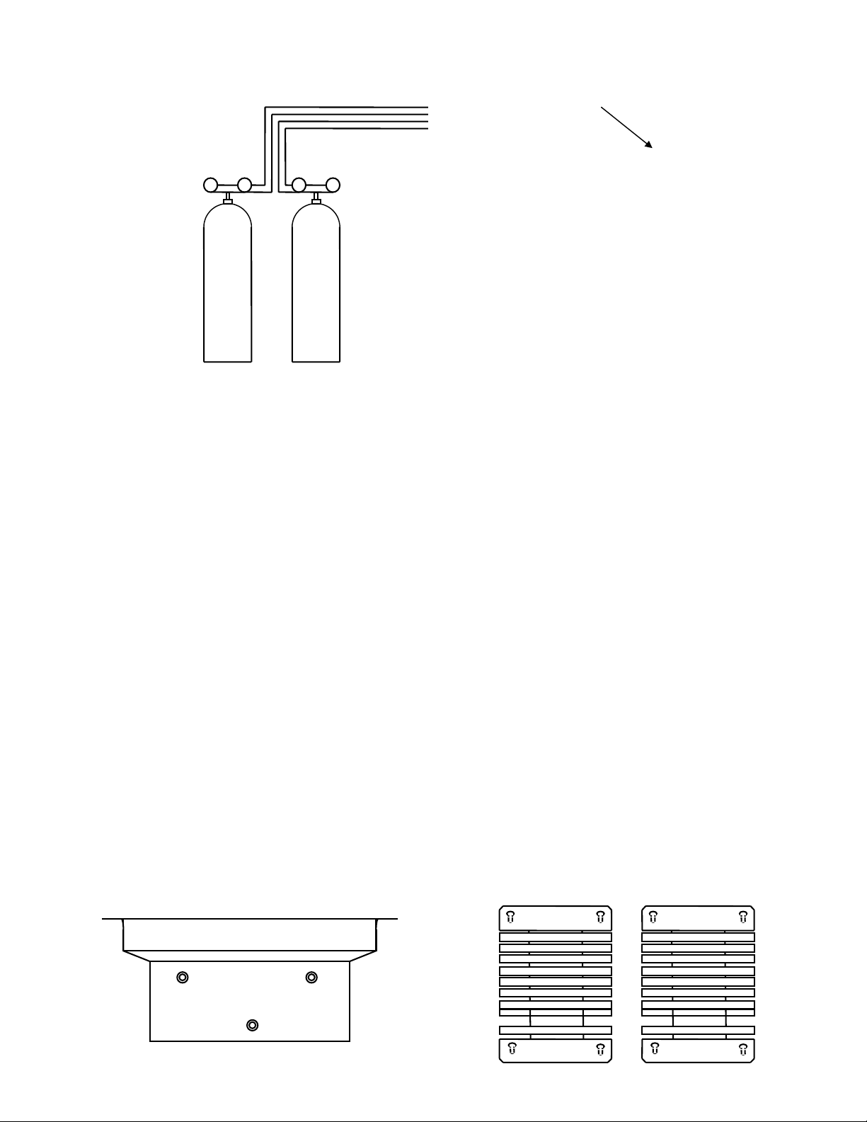
CONNECTIONS
TO CO2 FITTING
SET PRESSURE AT 10 PSI.
PRESSURE REGULATORS AND GAUGES MUST
BE INSTALLED ON EACH TANK. CHECK LOCAL
GAS SUPPLIER FOR PROPER REGULATORS.
IF AIR PUMP IS USED INSTEAD OF TANK,
AIR MUST BE FILTERED TO REMOVE WATER,
OIL AND DIRT.
100% AIR 100% CO2
Turn all flow meters on the incubator fully clockwise (closed). Connect air
and CO2 supply lines to their respective fittings on the back of the unit. Use 1/4"
ID tubing, flexible metal hose, etc., (meeting local codes), with filters to insure
that the air and CO2 are free of contaminants, for gas lines.
Set the supply regulators at 10 psi. Check all of the connections for leaks.
NOTE: FOR DUAL CHAMBER MODELS, EACH CHAMBER HAS A SEPARATE SET OF AIR
AND GAS FITTINGS.
WARNING: HIGH CONCENTRATIONS OF CARBON DIOXIDE PRODUCE
METABOLIC ABNORMALITIES, DISTURBANCES OF THE CENTRAL
NERVOUS SYSTEM AND CARDIAC INSTABILITY. UNCONSCIOUSNESS
MAY OCCUR AT CONCENTRATIONS ABOVE 10%.
INSTALLATION: (Con’t)
SHELVING/PLENUM INSTALLATION-SELF-SUPPORTING SYSTEM COMPONENTS:
TOP PLENUM SHELF SUPPORT SIDE PANELS
11
REAR COVER PANEL
SHELVING/PLENUM INSTALLATION-SELF-SUPPORTING SYSTEM ASSEMBLED
TOP PLENUM
SHELF SUPPORT SHELF SUPPORT
SIDE PANEL SIDE PANEL
REAR COVER PANEL
INSTALLATION: (Con’t)
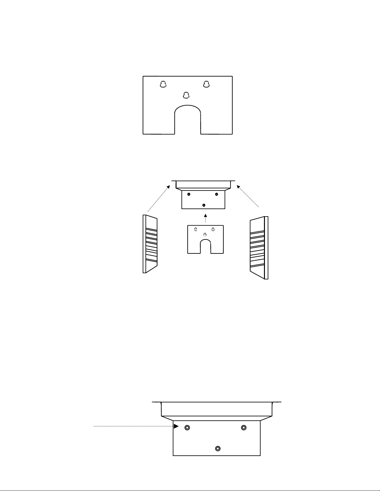
SHELVING AND PLENUM INSTALLATION-4 STEPS:
NOTE: NO TOOLS OR FASTENERS ARE REQUIRED. THE COMPONENTS FIT
TOGETHER INTO A SELF-SUPPORTING ASSEMBLY.
TOP PLENUM, HEAD-ON VIEW:
KEYWAY STUDS
(ONTO WHICH THE CHAMBER’S REAR
COVER PANEL KEYHOLE SLOTS WILL FIT)
12

TOP PLENUM, DOWN VIEW:
KEYHOLE SLOTS
(ONE IN EACH CORNER)
SPACERS STUDS
(
ASSURE THAT CIRCULATION FAN BLADES
DO NOT STRIKE THE PLENUM)
1. Open the outer and inner front chamber doors. Hold the top
plenum with the spacer studs up and the keyway studs toward the
rear. Tilt the panel at an angle and carefully move it into the
chamber while lifting and centering it at the top of the chamber.
Insert the larger keyhole slots located at the plenum’s corners over
the four studs suspended from the chamber ceiling. Slide the top
plenum toward the rear of the chamber locking the plenum into
place on the studs.
REAR
FAN VENTS
FRONT
INSTALLATION: (Con’t)
SHELVING AND PLENUM INSTALLATION: (Con’t)
SHELF SUPPORT SIDE PANELS (2), HEAD ON VIEW:
2. With the top plenum properly secured to the chamber ceiling, a
space on each side of the plenum is created into which the top of
13

each of the shelf support side panels will fit. Tilt a support side
panel at an angle and move it into the chamber. Carefully slide the
panel over the studs protruding from one side of the chamber wall
and lock it into place. Repeat this procedure on the other side to
install the second side panel.
REAR COVER PANEL, HEAD-ON VIEW:
TOP PLENUM
REAR PANEL
KEYHOLE SLOTS
(FIT OVER AND ONTO TOP PLENUM
KEYWAY STUDS)
KEYWAY STUDS
3. Move the rear cover panel into the chamber and place its keyhole slots
over and onto the top plenum keyway studs, moving the back wall slots
down and locking them onto the keyway studs.
INSTALLATION: (Con’t)
PORT STOPPER:
REAR COVER PANEL
PORT STOPPER INSTALLED
Insert the inner, narrower edge of the port stopper into the port opening located
on the rear chamber wall. Make sure the outer, wider edge is flush with the rear
chamber wall.
INSIDE REAR CHAMBER WALL, SIDE VIEW
14

OUTSIDE CHAMBER REAR INSIDE CHAMBER FRONT
FALSE BACK WALL, HEAD-ON VIEW:
TOP PLENUM
REAR PANEL
KEYHOLE SLOTS
(FIT OVER AND ONTO TOP PLENUM
KEYWAY STUDS)
STOPPER PUSHED FLUSH AGAINST INSIDE
REAR OF CHAMBER WALL, SIDE VIEW
KEYWAY STUDS
3. Move the rear cover panel into the chamber placing its keyhole slots over
and onto the top plenum keyway studs, moving the back wall slots
down,locking them onto the keyway studs.
INSTALLATION: (Con’t)
TOP PLENUM, UP VIEW:
BASE
HEAD
LOCKING
GROMMET
FOUR
KEYLOCK HOLES
4. Press a locking grommet (two supplied) into the two front keyhole slots
adjacent to the stud from which the top plenum is secured. Make sure
that the entire head of the locking grommet is inserted into the keyhole
slot. This prevents the top plenum from being accidentally pulled out.
FRONT
REAR
15

INSTALLATION: (Con’t)
INSTALLATION OF GAS FILTER INTERFACE ASSEMBLY KIT #018-514-00:
Note: One kit should be connected to the air outlet and another kit to the CO2 outlet on
the back of the incubator.
KIT #018-514-00 INCLUDES:
• 4, Hose Clamps (#250-331-00)
• 1, In-Line Filter (#525-034-00)
• 1, 10 ft. (4.57m) length of 1/4” (6.35mm) ID PVC tubing (#720-418-00)
INSTALLATION PROCEDURE:
See next page for illustration.
• Turn the unit’s power switch to the OFF position.
• Connect one length of tubing to CO2 tank gas outlet and another length of
tubing to the air tank outlet.
• Connect remaining end of 1/4” (6.35 mm) ID tubing to hose barb on one
side of in-line filter and secure with hose clamp, connect another length of
same size tubing to hose barb on filter’s other side and secure with hose
clamp. This is to be done for both air and CO2.
16

• Connect remaining end of tubing with in-line filter in place to the
appropriate gas and air inlet fittings on the back of the unit.
• Set the supply regulators at 10 psi.
• Check all of the connections for leaks.
• Turn the unit power switch to the ON position.
WARNING: HIGH CONCENTRATIONS OF CARBON DIOXIDE PRODUCE
METABOLIC ABNORMALITIES, DISTURBANCES OF THE CENTRAL
NERVOUS SYSTEM AND CARDIAC INSTABILITY—UNCONSCIOUSNESS
MAY OCCUR AT CONCENTRATIONS ABOVE 10%.
INSTALLATION: (Con’t)
INSTALLATION OF GAS FILTER INTERFACE ASSEMBLY KIT #018-514-00: (Con’t)
BACK OF UNIT
REAR PANEL VIEW, EXTERIOR:
IN-LINE FILTER BACK OF UNIT
#525-034-00
HOSE CLAMP HOSE CLAMP
1/4” ID TUBING
#720-418-00
#250-331-00 #250-331-00
HOSE CLAMP 1/4” HOSE BARB
#250-331-00 CONNECTIONS
SET PRESSURE AT 10 PSI.
(CO2 FITTING)
17

100% CO2
PRESSURE REGULATORS AND GAUGES MUST
BE INSTALLED ON EACH TANK. CHECK LOCAL
GAS SUPPLIER FOR PROPER REGULATORS.
INSTALLATION: (Con’t)
CO2 CONNECTION: STANDARD AND SIPHON TYPE CO2 GAS CYLINDERS
STANDARD TYPE (CORRECT) SIPHON TYPE (INCORRECT)
2
1135
246
38
7
1. Compressed Gas Association 1. Warning tag indicating that
#320 connector. cylinder is siphoning type.
2. Gas head-space. 2.* Aluminum ring.
3. Liquid CO2 filled to 68% 3.* Gold band.
equal weight of water that 4.* Stamp or marking on cylinder:
18

cylinder would hold at 60ºF. "Siphon" or "Eductor Tube".
5.* Valve should be of special type for
service.
6.* Withdrawal tube draws up the liquid
CO2.
7.* Gas head space.
8.* Liquid CO2 filled to 68% equal weight of
water that cylinder will hold at 60ºF.
*NOTE: SOME GAS SUPPLIERS WILL HAVE NO MARKINGS TO INDICATE AN "EDUCTOR
TUBE" OR "SIPHON" TYPE CYLINDER—BE SURE TO ORDER DRY, LAB-GRADE CO2.
Be sure to obtain a dual-stage regulator for the CO2 tank that is to be
installed according to local codes. Connect ¼" ID flexible tubing to the regulator.
Connect the other end of the tubing to the unit's CO2 inlet located on the back top
panel. Insert tubing over hose barb and fasten with an appropriate clamp to
assure a proper connection. Adjust the regulator for 10 psi when CO2 is to be
injected into chamber. For optimum results, do not exceed or reduce this
pressure.
INSTALLATION: (Con’t)
BE ADVISED:
IT IS OUR RECOMMENDATION THAT THIS UNIT RUN 24 HOURS EMPTY
BEFORE INTRODUCING MEDIA TO BE INCUBATED. THIS WILL FACILITATE
EASE OF SERVICING IF REQUIRED AS WELL AS NULLIFY THE NEED TO
DECONTAMINATE THE CHAMBER IN THE EVENT A PROBLEM OCCURS.
THIS UNIT CANNOT BE ACCEPTED FOR SERVICING OR CREDIT BY LABLINE UNLESS ACCOMPANIED BY A COMPLETED CERTIFICATION OF
DECONTAMINATION FORM, INCLUDED AT THE BEGINNING OF THIS
MANUAL.
19

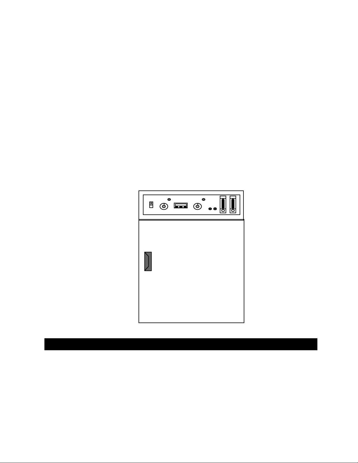
CONTROL PANEL
1 2 3 4 5 6 7 8 9 10
1. POWER SWITCH 6. KWIK-INJECT STATUS LAMP
#440-359-00 #360-233-01 (LAMP BASE)*
2. HI-LIMIT THERMOSTAT . 7. INJECTION BUTTON
#920-301-00 (THERMOSTAT), #560-223-00 (KNOB)*
3. HI-LIMIT THERMOSTAT STATUS LAMP 9. AIR FLOW METER
#360-233-01 (LAMP BASE)* #660-101-00*
4 TEMPERATURE CONTROLLER 10. CO2 FLOW METER
#485-360-00* #660-100-00*
5. KWIK-INJECT TIMER
#485-180-00*
SECTION 5
OPERATION
8. SAMPLE ACCESS PORT
20

START UP:
• Push the power switch (1) to ON—it will light when power is on. Dual
chamber models have 2 separate power switches that light; dual chambers
can be used independently or together.
• Rotate the hi-limit thermostat (2) knob fully clockwise; then set the
temperature controller (4) to the desired temperature set point.
• Repeat second and third steps as needed until set point is maintained.
*AS LISTED ON UPCOMING REPLACEMENT PARTS LIST
OPERATION: (Con’t)
CONTROL PANEL
1 2 3 4 5 6 7 8 9 10
1. POWER SWITCH 6. KWIK-INJECT STATUS LAMP
#440-359-00 #360-233-01 (LAMP BASE)*
2. HI-LIMIT THERMOSTAT . 7. INJECTION BUTTON
#920-301-00 (THERMOSTAT), #560-223-00 (KNOB)*
3. HI-LIMIT THERMOSTAT STATUS LAMP 9. AIR FLOW METER
#360-233-01 (LAMP BASE)* #660-101-00*
4 TEMPERATURE CONTROLLER 10. CO2 FLOW METER
#485-360-00* #660-100-00*
5. KWIK-INJECT TIMER
#485-180-00*
8. SAMPLE ACCESS PORT
SETTING THE HI-LIMIT THERMOSTAT:
• When the temperature set point is achieved, turn the hi-limit thermostat (2)
counterclockwise until the hi-limit thermostat status lamp (3) lights.
• Now rotate the HI-LIMIT thermostat clockwise 30 degrees of rotation past
the point where the lamp goes out. THIS DISTANCE SHOULD BE
21

SIMILAR TO THE DISTANCE FROM THE TWELVE O’CLOCK TO THE
ONE O’CLOCK POSITIONS. This establishes a buffer of a few degrees
between the operating set point and the HI-LIMIT temperature set point
and allows control to function normally.
NOTE: THE H-LIMIT SETTING MUST BE CHANGED EACH TIME THE CONTROL
SETTING (SETPOINT) IS CHANGED.
OPERATION: (Con’t)
TEMPERATURE CONTROLLER:
HEAT INDICATOR CHAMBER OR SET POINT TEMPERATURE
60.0
4 WV
1. CONTROLLER SELF-TEST: When the incubator is powered up the controller
will display 8888 along with the three decimal points and the heat ON indicator
lamp. The display will then blank out for 2 seconds before showing the chamber
temperature.
2. HEAT ON INDICATOR: The heat ON indicator lamp is lit when the chamber
heater is receiving power. The lamp will normally flash when the chamber
temperature is at set point.
3. SET POINT ADJUSTMENTS: The temperature controller normally displays the
chamber temperature. To view or change the temperature set point proceed as
follows:
PRESS CONTROLLER
4 View set point
4 W Decrease set point
22

4 V Increase set point
A. Press and hold the star key and use either the up or down arrow-key
to adjust the set point to the desired temperature. Release the star
key.
B. Allow at least 30 minutes for the chamber temperature to stabilize.
OPERATION: (Con’t)
TEMPERATURE CONTROLLER: (Con’t)
AUTO-TUNE:
The auto-tune program automatically adjusts the controller parameters to
achieve optimal temperature control.
It is not necessary to run the auto-tune program when setting up the
incubator. However, if the temperature appears to be unstable, the auto-tune
program can be run using the procedure shown below:
FOR BEST RESULTS:
• Set the usual set point temperature and use normal load conditions.
• Allow the incubator to stabilize at set point for at least 30 minutes.
AUTO-TUNING PROCEDURE:
A. Enter the program mode by pressing and holding BOTH the up and down
arrow-keys for 3 seconds.
B. Release BOTH arrow-keys when tunE is displayed.
C. The controller display should now be alternating between tunE and
oFF.
D. Press and hold the “STAR” (4) key. Press and release the up arrow-key
until At.SP is displayed. Release the “STAR” (4) key.
E. After one minute has elapsed, the controller display will begin to alternate
between showing the chamber temperature, tunE and At.SP.
F. Allow the program to run until the display again shows only the chamber
temperature.
23

OPERATION: (Con’t)
TEMPERATURE CONTROLLER: (Con’t)
TEMPERATURE CALIBRATION:
A. Place a calibrated thermometer near the approximate geometric center of
the chamber.
B. Press and hold the “STAR” (4) key and using the up or down arrow-key,
adjust the set point to the desired temperature.
C. Allow the unit to run for at least 30 minutes.
D. The controller display should now be indicating the set point temperature.
Make note of the thermometer reading.
E. Press and hold both arrow-keys until the controller display indicates
tunE. Release the arrow-keys. Press and release the down arrow-key,
the display should now indicate LEUL. Press and hold the “STAR” (4)
key and using the up arrow-key adjust the display to read 3. Release the
“STAR” (4) key. Press and release the up arrow-key until the display
indicates Zero. The display should now alternate between Zero and a
numerical value.
F. Using the examples shown below and the thermocouple value obtained in
step above, enter the correct Zero value into the controller by pressing the
“STAR” (4) key and using the up or down arrow-keys. If there is already
a Zero value present then add the new value to the one already present.
Thermometer = 55 °C Thermometer = 65 °C
Controller Reading = 60 °C Controller Reading = 60 °C
Subtract = -5 °C Subtract = +5 °C
Enter Zero value of -5 °C Enter Zero value of +5 °C
G. When the correct Zero value has been entered, press and hold the two
arrow-keys together until the display again indicates the chamber
temperature. If the procedure was done correctly, the controller display
should now agree with the thermometer reading to within ±0.5ºC.
H. Allow the unit to run for at least 30 minutes.
24

I. Re-check the thermometer reading, the controller display and the
thermometer should agree to within ±0.5ºC. If not, repeat steps D, E
and F above.
OPERATION: (Con’t)
LOADING THE INCUBATOR:
Load the chamber, spacing the items as far apart as possible for
maximum air circulation.
AIR/GAS RATIO:
Set the flow meters to obtain the required air and CO2 flow—using the
lowest possible CO2 flow rate will help to conserve gas.
Use one of the following formulas or the nomogram on upcoming page
to find the desired air-to-gas ratio:
R= % CO2 in the chamber atmosphere
A = Air flow in liters/minute
C = CO2 flow in liters/minute
Equation 1 (to be used if air and CO2 flow rates are known):
R = C x 100
A + C
Equation 2 (to be used if air flow rate and % CO2 are known):
C = RA liters/min.
100 - R
Equation 3 (to be used if CO2 flow rate and % CO2 are known):
A = 100C - RC liters/min.
R
Example 1: If a CO2 percentage of 15% is desired at a flow rate of 0.4
liters/min. of CO2, use Equation 3:
A = 100 (0.4) - 15 (0.4) = 40 - 6
15 15
= 2.26 liters/min. of air
25

Example 2: If flow rates are set 0.1 liters/min. of CO2 and 3 liters/min. of
air, use Equation 1 to find percentage of CO2:
B = 0.1 x 100 = 3.2% CO2 in chamber
3.0 + 0.1 atmosphere
OPERATION: (Con’t)
AIR/CO2 RATIO NOMOGRAM:
CO2 26242220181614 12 10
CO2 10 9.0
L
I9 8.0
T
E8 7.0
R
S7
/
M6 6.0
I
N5 5.0
U
T4 4.0
E
3 3.0
2.5 2.5
2 2.0
1.5 1.5
1.0 1.0
.9
.8 0.8
.7
.6 0.6
.5
.4 0.4
.3
.25
.2
.16
.15
%
CO2
26

.1
1 1.5 2 2.5 3 4 5 6 7 8 9 10 15 20 25 30 40 50 60 70 80 90 100
LITERS PER MINUTE, AIR
1. DRAW A VERTICAL LINE FROM THE POINT THAT REPRESENTS THE AIR FLOW ON THE HORIZONTAL
AXIS UNTIL IT INTERSECTS A DIAGONAL LINE INDICATING THE REQUIRED VOLUME (%) OF CO2 FLOW; 2.
RUN A HORIZONTAL LINE TO THE VERTICAL AXIS TO FIND REQUIRED FLOW OF CO2 IN LITERS/MINUTE, 3.
TO OBTAIN THE AIRFLOW (IF CO2 FLOW IN LITERS/MINUTE AND % CO2 ARE KNOWN), REVERSE THIS
PROCEDURE.
OPERATION: (Con’t)
OPERATING SUGGESTIONS:
• In order to obtain and maintain the desired CO2 gas pressure, periodically
check the tightness and integrity of the gasket that secures the glass door
to the chamber.
• To be sure of maintaining desired gas pressure, periodically check outflow
pressure from gas supply source.
• If maintaining humidity conditions within the chamber, check water level in
pan and replenish as necessary.
• After power is disconnected to the unit, do not permit humidity water to
remain in the unit. Remove any pans and/or dry the interior thoroughly.
• Insofar as possible, keep the incubator door closed in order to reduce the
possibility of fungus growth starting from airborne organisms entering the
chamber.
DOOR DEFOGGER:
The door heat control on the back panel should be off except when
fogging of the inner door occurs. If this happens close the outer door and turn on
the heat control. Rotate counterclockwise to increase heat and clockwise to
decrease heat. Wait a few minutes before opening door to see if fog dissipates.
If not, turn control in increments of 1 to higher setting.
CO2 SAMPLING/MEASUREMENT:
Insert sample probe into the sample access port on the control panel
making sure that a tight seal is attained. Obtain a sample of CO2 sufficiently
large to meet the requirements of the analytical apparatus or procedure being
used. Perform CO2 analysis.
27

OPERATION: (Con’t)
HINTS ON USING THE FYRITE:*
The following information is intended to supplement that found in the
Fyrite manual and is based on experience working with users of our Incubators.
One of the most important aspects of using the Fyrite procedure
and one that is frequently overlooked is the condition of the fluid. The Fyrite
accepts a sample of the Incubator's environment into its own chamber where it is
absorbed by the Fyrite fluid to determine the CO2 percentage or tension. Of
special importance is keeping outside air from the sample drawn from the
Incubator. Any outside air contaminating the sample is detrimental to an
accurate reading and, more importantly, to the growth of your cells.
Inspection of the fluid should be performed only with the user wearing
protective gloves, as the Fyrite fluid is slightly corrosive. The inspection should
review the following:
• THE DATE OF THE LAST FLUID CHANGE: Old fluid will not absorb as
much CO2 and will produce a false reading. This may lead the user to
recalibrate the Incubator to higher CO2 tensions that can prove lethal to
cell cultures. Fyrite fluid should be changed after approximately 350 uses.
This approximates a change of fluid once a year if the Fyrite procedure is
carried out on a daily basis. Keep track of the number of uses and if the
Fyrite is used with more than one Incubator. Experience shows that the
color of the fluid is not as important as the age of fluid.
• CHECK THE CONTAINMENT VESSEL AND HOSES AT LEAST ONCE A
MONTH: Make sure that there are no cracks in the vessel or leakage of
fluid to the outside of the container. This can indicate a leaky seal or
internal crack. Hoses should be stretched slightly and inspected for
cracks or holes. This is critical as cracks and/or holes in the hoses can
draw in outside ambient air and produce a false reading.
• CHECK THE FLUID DAILY AND ADJUST THE SLIDE GAUGE TO READ
ZERO: If you have adjusted the slide gauge all the way down and the fluid
level is still too low, place a couple of drops of distilled water into the
plunger on the top of the Fyrite. Depress the plunger and the water will
transfer into the Fyrite causing the fluid level to rise. Repeat this
procedure until the fluid level reads correctly.
CAUTION: A LITTLE WATER GOES A LONG WAY—USE ONLY A COUPLE
OF DROPS OF DISTILLED WATER AT A TIME.
28

CAUTION: DO NOT USE FYRITE FLUID TO ADJUST THE LEVEL OF FLUID
USE DISTILLED WATER ONLY. THE ONLY TIME TO USE FRESH FYRITE
FLUID IS WHEN YOU CHANGE IT DUE TO THE AGE OF THE FLUID.
Inspect the Fyrite filter in the clear plastic casing between the hoses for
any contamination or growth. Change it if necessary.
*Trademark Of Bacharach Instruments
OPERATION: (Con’t)
HINTS ON USING THE FYRITE:* (Con’t)
CAUTION: MAKE SURE THE FILTER IS MOIST BEFORE TAKING A READING—A
MOIST FILTER IS A MUST FOR AN ACCURATE READING.
To moisten the filter, remove the end of the short hose without the
squeeze bulb that connects to the Incubator. Add several drops of distilled water
to the filter, replace the hose and squeeze the bulb. Release the bulb and the
water will be drawn into the filter. Squeeze the bulb and quickly release it to
remove any excess water. This water, if any, comes out of the end of hose that
is closest to the squeeze bulb. This is the cupped end that is depressed onto the
Fyrite.
TAKING A FYRITE READING:
It is recommended that Fyrite CO2 and independent temperature
tests be performed at intervals to be determined individually or as dictated
by established protocol. Some laboratories conducting critical work may
want to record CO2 and temperature readings on a daily basis.
CAUTION: THE INCUBATOR MUST BE STABLE.
First, clear the Fyrite of any residue CO2. Simply depress the plunger on
the head or the top of the Fyrite taking care not to cover the hole—this
introduces fresh ambient air into the Fyrite chamber. Release the plunger and
turn the Fyrite upside down, holding it at a 45-degree angle until most of the
bubbles surface and the fluid has filled the head. Even the smallest bubbles
may contain CO2, so that it is important to let most of the smaller bubbles
surface.
Now turn it right side up and hold it at 45 degrees. Allow the fluid to fill the
Fyrite and depress the plunger again—this clears the Fyrite of any CO2 that
might cause a false reading.
Next, attach the filter side of the hose to the Incubator's CO2 sample port.
Remove the brass tube, if present, from the Fyrite hose, as it is not needed and
attach the hose to the CO2 sample port. The brass tube was once used with
older Incubators that utilized a hole in the Incubator wall or door to measure
CO2 but this method proved to cause contamination problems.
LOOK AT YOUR FYRITE GAUGE AND ADJUST THE ZERO IF
NECESSARY.
Take the squeeze bulb end of the hose and with the hole of the cupped
end facing down, place it onto the plunger of the Fyrite and hold it firmly in
position.
29

IMPORTANT: ONCE YOU HAVE DEPRESSED THE PLUNGER OF THE
FYRITE, IT IS CRITICAL THAT IT NOT BE RELEASED DURING THE
FOLLOWING PROCEDURE.
OPERATION: (Con’t)
TAKING A FYRITE READING: (Con’t)
Depress the plunger and hold it down. It is very important not to allow the
plunger to spring up—if this occurs, an already existing reading will be repeated.
It will not matter how many times the squeeze bulb is pumped, as long the
plunger is held down only one sample will be introduced to the Fyrite. But,
by releasing the plunger and immediately pushing it back down, an additional
sample will be added to the Fyrite chamber causing the reading to double or
triple. In the event that it is difficult to hold the plunger down while pumping the
squeeze bulb, find a more suitable or comfortable position.
Without releasing the plunger, pump the squeeze bulb at least 20 to 30
times—this assures complete and thorough transfer of the sample to the Fyrite
chamber. Once the bulb has been pumped the required number of times, HOLD
THE SQUEEZE BULB IN THE SQUEEZED-POSITION and release the
pressure on the cup that will also release the plunger—this traps the sample
from the Incubator in the Fyrite chamber and allows the fluid to absorb the CO2.
With the plunger now released, turn the Fyrite upside down again and hold
at a 45-degree angle to allow the smaller bubbles to surface while the fluid fills
the chamber head. Reverse and turn Fyrite right side up and hold at a 45degree angle to allow the same thing to happen. Repeat this procedure—hold
upside down at 45-degree angle and right side up at 45-degree angle. Finish by
shaking the Fyrite slightly while holding at 45-degree angle to allow residue
droplets of fluid to drain into the measuring tube.
Read the gauge: It should match or be close to your CO2 set point. It is
possible to be off as much as ±3%. With a reading of more than 8%, it is
possible that two samples have been introduced, or the Incubator is out of
calibration. If a wide variation between the reading and CO2 set point exists, it
is recommended that the sampling and measurement procedure be repeated.
Once the possibility of any error in Fyrite reading has been eliminated,
calibrate the Incubator to conform to the reading obtained.
30

BE ADVISED:
NOTE: MAKE NO ATTEMPT TO SERVICE OR REPAIR A LAB-LINE PRODUCT UNDER
WARRANTY BEFORE CONSULTING YOUR LAB-LINE DEALER. AFTER THE WARRANTY
PERIOD, SUCH CONSULTATION IS STILL ADVISED, ESPECIALLY WHEN THE REPAIR
MAY BE TECHNICALLY SOPHISTICATED OR DIFFICULT.
IF ASSISTANCE IS NEEDED BEYOND WHAT THE DISTRIBUTOR CAN PROVIDE, PLEASE
CALL THE LAB-LINE CUSTOMER RELATIONS DEPARTMENT AT (563) 556-2241 OR
(800) 522-5463. NO MERCHANDISE, HOWEVER, SHOULD BE RETURNED DIRECTLY TO
LAB-LINE WITHOUT PRIOR APPROVAL FROM LAB-LINE.
CAUTION: DISCONNECT PLUG FROM ELECTRICAL OUTLET BEFORE
ATTEMPTING ANY MAINTENANCE OR REPAIR OF THIS UNIT.
ROUTINE CLEANING:
Clean up spills immediately to prevent them from becoming baked on.
Drain water from the water compartment and clean all chamber components with
a solution of water and mild soap. Rinse thoroughly and dry. DO NOT use
chlorine-based solutions or cleansers, harsh abrasives or scouring pads with
metallic content. To remove built-up scale deposits, use a dilute acetic acid
solution and a synthetic scrubber.
SECTION 6
MAINTENANCE
CARE AND CLEANING OF STAINLESS STEEL:
CAUTION: DISCONNECT UNIT FROM POWER SOURCE PRIOR TO
CLEANING. WE RECOMMEND ALL SERVICE BE PERFORMED BY
QUALIFIED SERVICE PERSONNEL.
WARNING: ELECTROLYSIS CAN DAMAGE STAINLESS STEEL. THIS
OCCURS WHEN AN OBJECT IS ALLOWED TO REST DIRECTLY ON THE
SURFACE OF STAINLESS STEEL, TRAPPING MOISTURE THAT BECOMES
OXYGEN-STARVED, BUT IS SURROUNDED BY WATER-CONTAINING
OXYGEN.
31

MAINTENANCE: (Con’t)
THE ALLOY CALLED STAINLESS:
Stainless steel is an alloy of steel with chromium and nickel that
increase the metal’s resistance to rust and corrosion. Yet, if not properly cared
for, stainless steel can rust and corrode.
Exposure to air provides the passivation, or oxide layer coating, for clean
stainless by producing a thin, durable chromium-oxide film that forms rapidly
on the alloy surface to give stainless its characteristic “stainless” quality. Also
exposure of the surface to other oxidizing environments can produce a
passivating film or coating.
However, if free oxygen is not available due to scale or contamination
buildup the metal surface may become vulnerable to rusting and corrosion as
well as pitting. But by maintaining neutral pH and conducting frequent cleanings
with detergent and water, years of trouble-free service from stainless steel
products can be obtained.
SOME STAINLESS GUIDELINES TO CONSIDER:
Distilled water is recommended. Please note, if this water is very pure it
may be corrosive to stainless. When filling a bath or incubator, ALWAYS ADD 2
to 40 PPM (20 TO 40 MG/LITER) DISODIUM PHOSPHATE OR SODIUM
BICARBONATE, ADJUSTING DOSAGE TO PROVIDE A pH VALUE OF 7 TO 9.
If not available, use clean, aerated soft tap water provided the total solids
concentration is < 500 PPM.
WE DO NOT RECOMMEND USING 18 MEG OHM DEIONIZED WATER.
If this is the only source of treated water available—mix with regular tap water
at a 50/50 ratio.
THE pH FACTOR:
Check pH regularly. If pH is <6.0, add disodium phosphate to increase pH
to a 7 to 9 value. Sodium carbonate or sodium bicarbonate may be used but
they tend to form scale that must be rinsed out regularly. If pH is >10.0, add
sodium bisulfate to decrease pH to a 7 to 9 value. Avoid adding harsh alkalines
or acids since these may cause localized corrosion and result in unstable pH.
SPECIAL CONSIDERATIONS:
WARNING: IF IT IS NECESSARY TO USE THE FOLLOWING CHEMICALS,
LIMIT EXPOSURE TIME TO A MAXIMUM OF 3 HOURS—ALWAYS CLEAN
SURFACES IMMEDIATELY AFTER USE.
Chemicals that should be limited to a 3-hour maximum exposure time to
stainless steel are:
Aluminum chloride E.D.T.A. Potassium permanganate
Barium chloride Ferrous chloride Potassium thiocyanate
Calcium chloride Lysol Sodium hypochlorite
Chlorinated Lime Mercury salts Stannous chloride
Citric acid (boiling) Phenol Tartaric acid
Dakin’s solution
32

MAINTENANCE: (Con’t)
BE ADVISED: NEVER USE THE FOLLOWING ON STAINLESS STEEL:
Aqua regia
Ferric chloride
Iodine
Sodium acid
Sodium azide
Chemical spills, especially those agents listed here, should be removed
as soon as possible and the stainless steel surface cleaned with mild soapy
water followed by a clean water rinse.
CLEANSING AGENTS:
Anti-fungal and anti-bacterial additives are permissible to use as long as
the pH of the aqueous solution is kept within the range of 7 to 9. These are
available through laboratory distributors—but be sure to CONFIRM that they are
not harmful to stainless steel.
CLEANING METHODS:
Do not use any metallic pads. Instead, for stubborn stains, use a plastic
light-duty cleansing pad and rub GENTLY in the direction of the metal grain.
If stains continue to persist, use one of the following chemicals and methods.
CAUTION: EXTREME CARE MUST BE TAKEN WHEN HANDLING THESE
MATERIALS. ALWAYS WORK IN AN AREA WITH ADEQUATE VENTILATION.
USE THE PRECAUTIONS AS OUTLINED IN THE MATERIAL SAFETY DATA
SHEET (MSDS) AND THE MANUFACTURER’S INSTRUCTIONS FOR THE
PRODUCT BEING UTILIZED. ALSO, FOLLOW THE PERSONAL
PROTECTION INDEX FOUND IN THE HAZARDOUS MATERIALS
INFORMATION SYSTEM (HMIS) SECTION OF THE MSDS.
NOTE: THE USE AND DISPOSAL OF THESE CHEMICALS MAY BE REGULATED BY YOUR
LOCAL CITY CODES; CONSULT THOSE REGULATIONS BEFORE OF DISPOSING OF
THESE MATERIALS.
• Any of a variety of “scale removers” available at local supermarkets or
hardware stores used for the cleaning of coffee marks, humidifiers or
vaporizers.
• A 15% to 35% phosphoric acid solution available from laboratory supply
distributors for scale and rust removal. Allow solution to soak the surface
affected until rust and scale is loosened. Immediately follow with a clean
water rise.
• Citric acid based cleaners.
33

MAINTENANCE: (Con’t)
CLEANING METHODS: (Con’t)
• Bathroom tub and tile cleaners.
• A mixture of 20% nitric acid and 1.5% hydrofluoric acid or hyrochloric acid.
Swab solution on surface allowing it to remain until rust is loosened.
Immediately follow with a clean water rise. This method should ONLY be
used if SEVERE rust and scale stains are present.
• Oxalic acid 2% to 5% in warm water. Swab solution on surface allowing it
to remain until rust is loosened. Immediately follow with a clean water
rise. This method should ONLY be used if SEVERE rust and scale stains
are present.
Regardless of the approach utilized, ALWAYS follow the manufacturer’s
directions and allow the chemicals to do the cleaning with MINIMAL scrubbing.
Always follow cleanings with a clean water rinse. Air dry.
MATERIALS EFFECTIVE IN DISINFECTING:
• Glutaraldehyde
• Alcohol
BE ADVISED: THIS INFORMATION IS INTENDED AS GUIDELINES ONLY
AND LAB-LINE INSTRUMENTS, INC. MAKES NO CLAIM AS TO THE
SUITABILITY TO ANY PARTICULAR SITUATION. CONSULT YOUR STAFF
CHEMIST TO DETERMINE WHAT WOULD BE BEST FOR YOUR STAINLESS
STEEL PRODUCT AND LABORATORY.
REPLACING TEMPERATURE CONTROLLER:
1. Place ON/OFF switch in OFF position.
2. Unplug incubator from outlet power supply.
3. To remove controller from control housing:
• use both hands to firmly grip each side of the controller bezel
• press on the bezel side grips until the bezel tabs release
• slowly pull controller from housing
4. To install new, factory configured controller:
• Carefully slide new controller into controller housing.
NOTE: PCB contacts at rear of controller fit into contacts at rear of controller
housing
• Press controller bezel into controller housing until bezel tabs securely
lock controller into place
. Plug incubator into outlet power supply.
5
6. Place ON/OFF switch in ON position.
34

SECTION 7
REPLACEMENT PARTS
Axial Fan: 160-136-00
Air (5 liters/min.): 660-044-00
CO2 (0.5 liters/min.): 660-043-00
Gasket, Glass Door: 530-258-00
Gasket, Outer Door: 530-246-00
Outer Heater, 50 Watt: 340-378-00
Chamber Heater, 250 Watt: 340-350-01
Status Lamp Base (all models): 360-233-01
Switch, Power, 120V: 440-359-00
Switch Power, 240V: 440-292-00
Thermostat over-temperature): 920-301-00
Timer, Auto Reset: 485-180-00
Transformer, 240 V units: 460-283-00
RTD Temp. Sensor: 410-632-00
Configured Temperature Controller: 485-360-02
Circuit Breaker, 5 Amp, 240VAC: 330-118-00
Fuse, 1 Amp, 240V: 330-369-00
Gas Filter Interface Assembly: 018-514-00
Circuit Breaker, 10 Amp: 330-119-00
Green Lens Cover: 360-238-00
240V Green Pilot Light Base: 360-249-01
Wiring Schematic, 120V: 228-399-00
Wiring Schematic, 240V: 229-012-00
DESCRIPTION PART NUMBER
Cordset; 470-105-00
Feet, Leveling: 790-401-00
Flow meters:
Knob: 560-223-00
Knob: 560-225-00
Knob, Glass Door: 560-228-00
Solenoid Valve: 950-148-00
Solid State Relay: 400-233-00
Switch, SPST: 440-080-00
Heat Control: 920-251-00
Red Lens: 360-234-00
Glass Door: 540-258-00
Axial Fan: 160-194-00
Motor, 120V: 370-382-00
Motor, 240V: 370-383-00
NEED A PART? CALL THE LAB-LINE PARTS HOTLINE.
CALL: (800) 522-5463 or (563) 556-2241; FAX: (563) 589-0516.
LAB-LINE RESERVES THE RIGHT TO CHANGE SPECIFICATIONS WITHOUT PRIOR NOTICE.
35

WARRANTY
Page 1 of 2
LAB-LINE INSTRUMENTS, INC. (“Lab-Line”) warrants that the product manufactured by
Lab-Line shall be free of defects in materials and workmanship for a period of time
defined on the following page from the first to occur of (i) the date the product is sold by
Lab-Line or (ii) the date the product is purchased by the original retail customer (the
“Commencement Date”). Except as expressly stated above,
LAB-LINE MAKES NO OTHER WARRANTY, EXPRESSED OR IMPLIED, WITH
RESPECT TO THE PRODUCTS AND EXPRESSLY DISCLAIMS ANY AND ALL
WARRANTIES, INCLUDING BUT NOT LIMITED TO, WARRANTIES OF DESIGN,
MERCHANTABILITY AND FITNESS FOR A PARTICULAR PURPOSE.
An authorized representative of Lab-Line must perform all warranty inspections. In the
event of a defect covered by Lab-Line’s warranty, Lab-Line shall, as its sole obligation
and exclusive remedy, provide free replacement parts to remedy the defective product.
In addition, for products sold by Lab-Line within the continental United States or
Canada, Lab-Line shall provide free labor to repair the products with the replacement
parts, but only for a period of ninety (90) days from the Commencement Date.
Lab-Line’s warranty provided hereunder shall be null and void and without further force
or effect if there is any (i) repair made to the product by a party other than Lab-Line or
its duly authorized service representative, (ii) misuse (including use inconsistent with
written operating instructions for the product), mishandling, contamination, overheating,
modification or alteration of the product by any customer or third party or (iii) use of
replacement parts that are obtained from a party who is not an authorized dealer of LabLine.
IN NO EVENT SHALL LAB-LINE BE LIABLE TO ANY PARTY FOR ANY DIRECT,
INDIRECT, SPECIAL, INCIDENTAL, OR CONSEQUENTIAL DAMAGES, OR FOR
ANY DAMAGES RESULTING FROM LOSS OF USE OR PROFITS, ANTICIPATED
OR OTHERWISE, ARISING OUT OF OR IN CONNECTION WITH THE SALE, USE
OR PERFORMANCE OF ANY PRODUCTS, WHETHER SUCH CLAIM IS BASED ON
CONTRACT, TORT (INCLUDING NEGLIGENCE), ANY THEORY OF STRICT
LIABILITY OR REGULATORY ACTION.
The name of your nearest authorized Lab-Line dealer may be obtained by calling 1800-522-5463.
DESIGNERS AND MANUFACTURERS
A SUBSIDIARY of Barnstead|Thermolyne
1999 North 15th Ave.
PHONE: (563) 556-2241 or (800) 522-5463; FAX: (563) 589-0516
, Melrose Park, IL 60160-1491 USA
WARRANTY
36

Page 2 of 2
12 MONTH PARTS WARRANTY:
• All Environmental Chambers
• Low Temperature B. O. D. Incubators
• Animal Study Chamber
• Controlled Environment Centers
• Biological Work Station
• Refrigerators, Freezers
• Chromatography Refrigerators (5 year parts warranty on compressor only)
• Large Capacity Refrigerators and Freezers (5 year parts warranty on compressor
only)
24 MONTH PARTS WARRANTY:
• Frame Clamps, Frame Sets, Lab Jacks
• Saybolt Viscosimeter
• Timers, Samplers, Flasks
• Saf-T-Shield, Safety Tongs
• All Incubators & Ovens
• Dual Action Open Air Shaker
• Reciprocating Shakers (open air and water bath)
• Rockers and Rotators
• Low Cost Shakers
• Environ Blok Shaker
• Titer Plate Shaker
• Multi Wrist Shaker
• Water Baths (excluding Aquabaths), Ultrasonic Cleaners
• Slide Warmers
• Mixers, Stirrers, Hotplates
• Thermal Cyclers
• Blok Heaters
• Aquabaths, lifetime warranty on heaters
LIFETIME PARTS WARRANTY:
• All ORBITAL Shakers (not carrying a 24 month parts warranty) offer a lifetime
parts warranty on the drive mechanism and a 5 year warranty on all other parts
• Refrigerated Orbital Shakers carry a lifetime warranty on the drive mechanism,
1 year parts warranty on the compressor, and a 5 year warranty on all other
parts.
37

FIRST IN INSTRUMENTS SERVICING SCIENCE, INDUSTRY,
RESEARCH AND EDUCATION
SINCE 1908.
38

39

ACCESSORY CHECKLIST
The following loose parts and accessories are packed with
this unit. Before discarding any packing materials, please be sure that
nothing has been overlooked.
MODEL NOs: 320, 320-1, 322, 322-1, 325, 325-1
CHECKED BY: __________
DATE __________
PACKED BY __________
CHECKED ITEM PART NUMBER QUANTITY
_________ Shelves 593-108-00 5
Shelf Support
_________ Side Panels 019-451-00 2
Gas Filter
_________ Interface Assy* 018-514-00 2
Hose Barb Quick
_________ Connect Plug (460 Series) 950-170-00 2
_________ Operation Manual 056-761-00 1
_________ Warranty Card 528-022-00 1
Voltage Warning Tag
_________ (240 Volt) 528-009-00 1
_________ Mating Connector 420-006-00 1
_________ Locking Grommet 790-327-00 2
_________ Port Stopper 875-118-00 1
_________ Humidity Pan 018-637-00 1
_________ Rear Cover Panel 019-373-00 1
_________ Top Plenum 019-350-00 1
*Assy Includes 10’ PVC tubing #720-418-00
40
 Loading...