

Page 1
Operation Manual
PLM™ Series
Powered Loudspeaker Management™ systems
Rev 1.2.3
Item: OM-PLM
Page 2
Important Safety Instructions
1. Important Safety Instructions
Before using the device, be sure to carefully read the Safety Instruc tions. Keep this document with the device at all times.
1.1 Important Safety Instructions
1. Read these instructions.
2. Keep these instructions.
3. Heed all warnings.
4. Follow all instructions.
5. Do not use this apparatus near water.
6. Clean only with a dry cloth.
7. Do not block any ventilation openings. Install in accordance
with the manufacturer’s instructions.
8. Do not install near any heat sources such as radiators, heat
registers, stoves, or other apparatus (including ampliers)
that produce heat.
9. Do not defeat the safety purpose of the polarized or
grounding-type plug. A polarized plug has two blades with
one wider than the other. A grounding-type plug has two
blades and a third grounding prong. The wide blade or
the third prong is provided for your safety. If the provided
plug does not t into your outlet, consult an electrician for
replacement of the obsolete outlet.
10. Protect the power cord from being walked on or pinched,
particularly at plugs, convenience receptacles, and the point
where they exit from the apparatus.
11. Only use attachments/accessories specied by the
manufacturer.
12. Use only with a cart, stand, tripod, bracket, or table specied
by the manufacturer, or sold with the apparatus. When a
cart is used, use caution when moving the car t/apparatus
combination to avoid injury from tip-over.
13. Unplug this apparatus during lightning storms or when
unused for long periods of time.
14. Refer all servicing to qualied service personnel. Servicing
is required when the apparatus has been damaged in any
way, such as power-supply cord or plug is damaged, liquid
has been spilled or objects have fallen into the apparatus, the
apparatus has been exposed to rain or moisture, does not
operate normally, or has been dropped.
15. Use the mains plug to disconnect the apparatus from the
mains.
16. WARNING: To reduce the risk of re of electric shock, do not
expose this apparatus to rain or moisture.
17. Do not expose this equipment to dripping or splashing and
ensure that no objects lled with liquids, such as vases, are
placed on the equipment.
18. The mains plug of the power supply cord shall remain readily
operable.
19. Do not connect the unit’s output to any other voltage source,
such as battery, mains source, or power supply, regardless
of whether the unit is turned on or off.
20. Do not remove the top (or bottom) cover. Removal of the
cover will expose hazardous voltages. There are no user
serviceable par ts inside and removal may void the warranty.
21. An experienced user shall always supervise this professional
audio equipment, especially if inexperienced adults or
minors are using the equipment.
22. The US National Differences clause 16.3 requires that
network cables must be ame rated V W-1.
To prevent electric shock do not remove top or bottom covers.
No user serviceable parts inside, refer servicing to qualied
service personnel.
À prévenir le choc électrique n’enlevez pas les couvercles. Il n’y a
pas des parties serviceable à l’intérieur, tous reparations doit etre
faire par personnel qualié seulment.
To completely disconnect this equipment from the AC mains,
disconnect the power supply cord plug from the AC receptacle.
The mains plug of the power supply cord shall remain readily
operable.
Pour démonter complètement l’équipement de l’alimentation
générale, démonter le câble d’alimentation de son réceptacle. La
prise d’alimentation restera aisément fonctionnelle.
1.2 Standards
This equipment conforms to the requirements of the EMC Directive 2004/108/EC
and the requirements of the Low Voltage
Directive 2006/95/EC.
Standards applied: EMC Emission
EN55103 -1, E3
EMC Immunity EN55103-2, E3, with S/N
below 1% at normal operation level.
Electrical Safety EN60 06 5, Class I
This equipment is tested and listed according to the U.S. safety standard ANSI/ UL
60065 and Canadian safety standard CSA
C22.2 NO. 60065. Intertek made the tests
and they are a Nationally Recognized Testing Laboratory (NRTL).
1.3 Explanation of Graphical Symbols
The lightning bolt triangle is used to alert the user to
the presence of un -insulated “dangerous voltages”
within the unit’s chassis that may be of sufcient
magnitude to constitute a risk of electric shock to
humans.
The exclamation point triangle is used to alert the
user to presence of important operating and service
instructions in the literature accompanying the
product.
PLM Series Operation Manual rev 1.2.3
i
Page 3
Important Safety Instructions
1.4 WARNING
To reduce risk of re or electric shock, do not expose this apparatus to rain or moisture.
Pour réduire les risques de blessure ou le choc électrique, n’exposez pas l’appareil à la pluie ou à l’ humidité.
Do not expose this system/apparatus to dripping or splashing and ensure that no objects lled with liquids, such
as vases, are placed on the apparatus.
L’appareil ne doit pas être exposé à des egouttements d’eau ou des éclaboussures et de plus qu’aucun objet
rempli de liquide tel que des vases ne doit pas être placé sur l’appareil.
This apparatus must be connected to a mains socket outlet with a protective earthing connection.
Cet appareil doi t être raccordé á une prise de courant qui est branchée à la terre.
The mains plug is used as a disconnect device and shall remain readily operable.
Lorsque la prise du réseau d’alimentation est utilisés comme dispositif de déconnexion, ce dispositif doit
demeuré aisément accessible.
1.5 CAUTION
To reduce the risk of re or electric shock, do not remove screws. No user-ser viceable parts inside.
Refer servicing to qualied service personnel.
Pour réduire le risque d’incendie ou de choc électrique, ne pas retirer les vis. Aucune pièce réparable par
l’utilisateur. Coner l’entretien àpersonnel qualié.
1.6 FCC Compliance Notice (Radio Interference)
A sample of this product has been tested and complies with the limits for the European Electro Magnetic
Compatibility (EMC) directive. This equipment has also been tested and found to comply with the limits for a
Class B digital device, pursuant to Part 15 of the FCC Rules. These limits are designed to provide reasonable
protection against harmful interference from electrical equipment. This product uses radio frequency energy
and if not used or installed in accordance with these operating instructions, may cause interference to other
equipment, such as radio receivers.
However, there is no guarantee that interference will not occur in a particular installation. If this equipment
does cause harmful interference to radio or television reception, which can be determined by turning the
equipment on and off, the user is encouraged to try to correct the interference by one or more of the
following measures:
▸ Reorient or relocate the antenna.
▸ Increase the separation between the equipment and receiver.
▸ Connect the equipment to an outlet on a circuit different from that to which the receiver is connected.
ii
PLM Series Operation Manual rev 1.2.3
Page 4
Important Safety Instructions
▸ Check if the affected unit complies with the EMC limits for immunity, (CE-labeled). If not, address the
problem with the manufacturer or supplier. All electrical products sold in the EC must be approved for
immunity against electromagnetic elds, high voltage ashes, and radio interference.
▸ Consult the dealer or an experienced radio/ T V technician for help.
1.7 User Responsibility
1.7.1 Mains Connection Grounding
Your apparatus must be connected to a grounded socket outlet.
1.7.2 Speaker Output Hazard on Ampliers
Ampliers are capable of producing hazardous output voltages. To avoid electrical shock, do not touch
any exposed speaker wiring while the amplier is operating. The external wiring connected to the speaker
terminals shall be installed by a qualied person, or ready-made leads or cords of appropriate capacity shall
be used.
As the power output channels on ampliers produce high voltage, do not connect or disconnect
speaker cables when the mains power is on.
1.7.3 Speaker Damage
Amplier apparatus is very powerful and can be potentially dangerous to both loudspeakers and humans
alike. Many loudspeakers can be easily damaged or destroyed by overpowering them. Always check the
speaker’s continuous and peak power capabilities. Although the ampliers attenuators can be used to
reduce the overall gain, an increase of the input signal can result in full output power, which may cause
damage to connected speakers.
1.7.4 Maintenance
For safe and reliable operation, the dust lters on both sides of the front panel, behind the grilles, should be
removed and cleaned regularly to ensure maximum airow through the device.
If the dust lters are not maintained there will be safety risks; for example, high internal temperatures
could ignite the dust and start a re. There is also a risk that the unit will malfunction since it is dependent
on constant airow from front to rear. If the dust lters are not clean and the unit malfunctions, any resulting
problems will not be covered by the warranty.
PLM Series Operation Manual rev 1.2.3
iii
Page 5

Table of Contents
1. Important Safety Instructions ................................................................................................................i
1.1 Important Safety Instructions ............................................................................................................... i
1.2 Standards ..............................................................................................................................................i
1.3 Explanation of Graphical Symbols ......................................................................................................... i
1.4 WARNING ............................................................................................................................................ ii
1.5 CAUTION ............................................................................................................................................. ii
1.6 FCC Compliance Notice (Radio Interference) ....................................................................................... ii
1.7 User Responsibility ..............................................................................................................................iii
2. Welcome ...................................................................................................................................................1
2.1 Introduction ......................................................................................................................................... 1
2.2 Main Features ......................................................................................................................................1
2.3 Additional Documentation .................................................................................................................... 3
3. Installation ................................................................................................................................................ 4
3.1 Unpacking ............................................................................................................................................4
3.2 Mounting .............................................................................................................................................. 4
3.3 Cooling .................................................................................................................................................6
3.4 Operating Voltage ................................................................................................................................6
3.5 Grounding ............................................................................................................................................. 7
4. Product Overview ....................................................................................................................................9
4.1 Front Panel Overview ........................................................................................................................... 9
4.2 Back Panel Overview ......................................................................................................................... 12
5. Operation and Performance ................................................................................................................. 16
5.1 Operation Precautions ........................................................................................................................ 16
5.2 Power Output Performance ............................................................................................................... 16
5.3 Amplier and Load Protection Systems ............................................................................................. 18
5.4 Power Supply .....................................................................................................................................25
6. Signal Flow and Lake® Processing .......................................................................................................26
6.1 Signal Flow ........................................................................................................................................ 26
6.2 Lake Processing and Control .............................................................................................................. 28
6.3 Modules and Frames ........................................................................................................................28
6.4 Loudspeaker Crossover Conguration Overview ............................................................................... 29
6.5 Files and Presets ................................................................................................................................30
7. Front Panel Interface ............................................................................................................................. 31
7.1 Overview ............................................................................................................................................31
7.2 Front Panel Key Lock ..........................................................................................................................32
7.3 Power Button .................................................................................................................................. 32
7.4 Mute Enable Button .......................................................................................................................... 33
iv
PLM Series Operation Manual rev 1.2.3
Page 6

7.5 Meter Button .....................................................................................................................................33
7.6 Menu Button ...................................................................................................................................... 33
7.7 Exit Button
7.8 Dynamic Buttons, Controls and LEDs ................................................................................................34
7.9 Warning and Fault Indications ............................................................................................................ 39
7.10 Meter Mode ....................................................................................................................................... 42
7.11 Menu Mode .......................................................................................................................................46
8. Back Panel Interface ..............................................................................................................................63
8.1 Speaker Outputs ................................................................................................................................63
8.2 Analog Inputs and Outputs ................................................................................................................68
8.3 AES3 Digital I/O ................................................................................................................................70
8.4 RJ45 etherCON Network Connections .............................................................................................. 71
8.5 Power Inlet ......................................................................................................................................... 72
9. Appendix ................................................................................................................................................. 73
9.1 Faults and Warnings Overview ..........................................................................................................73
9.2 Maintenance ......................................................................................................................................77
9.3 Factory Default Settings.....................................................................................................................77
9.4 Current Draw and Thermal Dissipation Specications ....................................................................... 78
9.5 Glossary of Terms, Acronyms and Abbreviations ..............................................................................82
........................................................................................................................................33
10. Application Guide ..................................................................................................................................85
10.1 Rack I/O Panels ..................................................................................................................................85
10.2 Power Distribution..............................................................................................................................85
10.3 Gain Structure ....................................................................................................................................86
10.4 Gain / Level Optimization ...................................................................................................................88
10.5 Speaker Congurations ...................................................................................................................... 91
10.6 Digital Audio Connections .................................................................................................................. 92
10.7 Digital Clock Conguration ................................................................................................................. 95
11. Technical Specications .......................................................................................................................97
12. Warranty and Support ..........................................................................................................................98
12.1 General ..............................................................................................................................................98
12.2 International Warranties .....................................................................................................................98
12.3 Technical Assistance and Service ......................................................................................................98
12.4 Trademarks .........................................................................................................................................99
PLM Series Operation Manual rev 1.2.3
v
Page 7

Welcome
2. Welcome
2.1 Introduction
Thank you for choosing the Lab.gruppen PLM Series of Powered Loudspeaker Management systems for
your sound reinforcement needs. We are condent that you will be pleased with the performance, unique
features, conguration exibility, reliability, and long-term durability offered by this product.
For fast installation and use of this product, your welcome package includes a printed copy of the
PLM Series Quick Start & Field Reference Guide which contains the information required to safely install the
product and place it in service. Control and editing features are accessible via the front panel interface or via
the included Lake Controller software.
It is recommend that the Quick Start & Field Reference Guide and all product documentation on the
included CD-ROM is reviewed to ensure familiarity with the various conguration and control options.
Thank you again for placing your condence in Lab.gruppen products.
2.2 Main Features
The PLM Series incorporates a number of sophisticated technologies to ensure the best possible performance and many years of reliable operation. The following section summarizes the benets of each feature;
additional information is available in the reference manuals.
2.2.1 Amplier Platform
The PLM Series power output section has expanded upon Lab.gruppen’s robust, road-proven
FP+ Series ampliers. Features in common with the FP+ Series include extraordinary power density,
patented Class TD® output stages, Regulated Switch Mode Power Supply (R.SMPS™), the high-efciency
Intercooler® copper-nned cooling system, and a full suite of protection features. Signal inputs are analog,
AES digital, and Dante digital audio network; loop-through outputs or redundant pairs are provided for each
input type.
Please refer to section 5.3 for further information.
2.2.2 Amplier DSP (Digital Signal Processor)
Various features of PLM Series devices are controlled by the on-board DSP, some of which are summarized
in this section.
PLM Series Operation Manual rev 1.2.3
1
Page 8

Welcome
2.2.2.1 Input Gain (Sensitivity)
Input gain (sensitivity) is set in the digital domain for PLM Series devices, and may be controlled via the
Lake Controller software or front-panel interface.
2.2.2.2 ISVPL
The Inter-Sample Voltage Peak Limiter (ISVPL) tailors each power output to the characteristics of the
connected load. Please refer to section 5.3.1 for further information.
™
2.2.2.3 Load Verication & Performance Monitoring
A comprehensive set of proprietary DSP-based tools are provided for load verication and real-time performance monitoring. These functions utilize LoadLibrary, a comprehensive database for each loudspeaker
component of the connected load (usually one or more band-limited drivers in a multi-way system).
Using this data and a brief test signal, LoadSmart compares actual response to predicted response, identifying any malfunctioning components or connection errors. During the performance, SpeakerSafe™ monitors
real-time load status, including temperatures of the PLM amplier stages as well as magnets and voice
coils of connected loudspeakers. This allows operators to avoid power compression and identify potential
problems.
Please refer to the Lake Controller Operation Manual for detailed information on PLM Series load verication
and real-time performance monitoring functionality.
2.2.3 Lake Processing and Controller
PLM Series devices integrate seamlessly into the Lake Processing environment. Two processing modules
offer precise settings for gain, delay, crossover settings, equalization and limiting. Lake processing features
incorporated in each module include Raised Cosine Equalization™, linear phase crossovers, and LimiterMax™
loudspeaker protection. The Super Module feature allows hardware processing modules in two or more
separate devices to function as a single module in the Lake Controller software. Please refer to the
Lake Controller Operation Manual for further information.
2.2.4 Lake Analyzer Bridge
Lake Controller software provides integration with third-party real-time analyzers, providing simultaneous
measurement display and EQ adjustment via the Lake Controller.
The third-party measurement tools that can be integrated via the Analyzer Bridge include:
▸ Smaart Live Version 5.4
▸ Live-Capture Light / Live-Capture Pro
2
PLM Series Operation Manual rev 1.2.3
Page 9

Welcome
Smaart, distributed and supported by Rational Acoustics, provides real-time sound system measurement,
optimization and control. Smaart combines several powerful audio frequency measurement and analysis
tools.
Live-Capture, created by WaveCapture, offers easy-to-use software and measurement tools for sound
engineers, installers, consultants and designers. The Lake Analyzer Bridge in conjunction with Live-Capture
Light provides a completely free spectrum analyzer via your Lake Controller software interface.
2.2.5 Dante™ Audio Network
PLM Series devices include Dante digital audio networking as standard. Utilizing the latest advances in
Ethernet technology, Dante offers simplied system conguration and extremely low latency while delivering very high quality uncompressed digital audio across the Lake network. The Zen™ automatic conguration
feature enables plug-and-play setup without third-party DHCP or DNS servers. Dante is compatible with
high-bandwidth networks, allowing large numbers of audio channels to be distributed alongside control and
analyzer data.
2.3 Additional Documentation
This document, the PLM Series Operation Manual, serves as the primary reference source for detailed
information on the installation and operation of PLM Series Powered Loudspeaker Management systems. It
also provides detailed information on set-up and conguration using the front-panel interface.
If you intend to use the device as part of a networked system, or access features via the Lake Controller,
please refer to the various supporting documents which can be located via these methods:
▸ Start > Programs > Lake Controller > Documentation (after installing Lake Controller software)
▸ On the Installer CD-ROM or the downloaded software installer
▸ Online at: http://labgruppen.com/index.php/products/documentation/
PLM Series Operation Manual rev 1.2.3
3
Page 10

Installation
3. Installation
3.1 Unpacking
Carefully open the shipping carton and check for any damage to the device or the supplied accessories.
Every Lab.gruppen product is tested and inspected before leaving the factory and should arrive in perfect
condition. If any damage is discovered, please notify the shipping company immediately. Only the consignee
may initiate a claim with the carrier or their insurers for damage incurred during shipping. Save the carton
and packing materials for the carrier’s inspection.
In addition to the PLM, the shipping carton include the following items:
▸ PLM Series Quick Start & Field Reference Guide
▸ AC mains lead (power cable) with Neutrik® powerCON® connector
▸ Rear brackets for additional rack support (pair) along with associated mounting hardware
▸ Software Installer and Documentation CD-ROM
Please keep the original carton and associated packaging to facilitate shipping of the device should the need
arise.
3.2 Mounting
Airow for cooling the PLM is from front panel (intake) to rear panel (exit). Please ensure that no object,
such as rack doors or lids are placed at the front or rear of the rack to ensure that airow is maximized. This
device has no top or bottom vents and therefore may be stacked directly on top of each other.
Sufcient space should be available at the front of the rack to accommodate the handles, and at the rear to
accommodate connectors and cables; allowance must be made for cable or loom bends within a rack.
3.2.1 Rear Mounting
Two rear support brackets along with associated mounting hardware are included with the PLM, as shown
in Figure 3-1; it is recommended that these are used wherever possible. Fit the brackets to the vertical rails
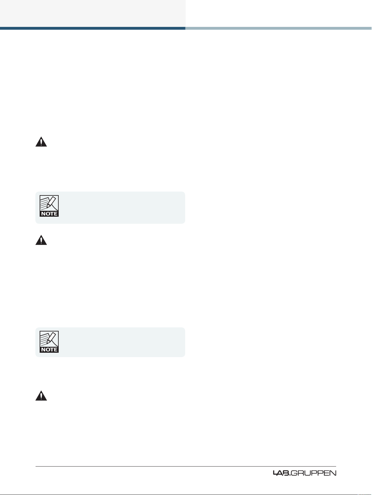
at the rear of the rack. Figure 3-2 and Figure 3-3 show the tting options for xed and removable installation.
The support brackets are reversible and may be tted to point either to the front or rear of the rack; the
orientation used depends on the rack depth and position of the rear rack rails.
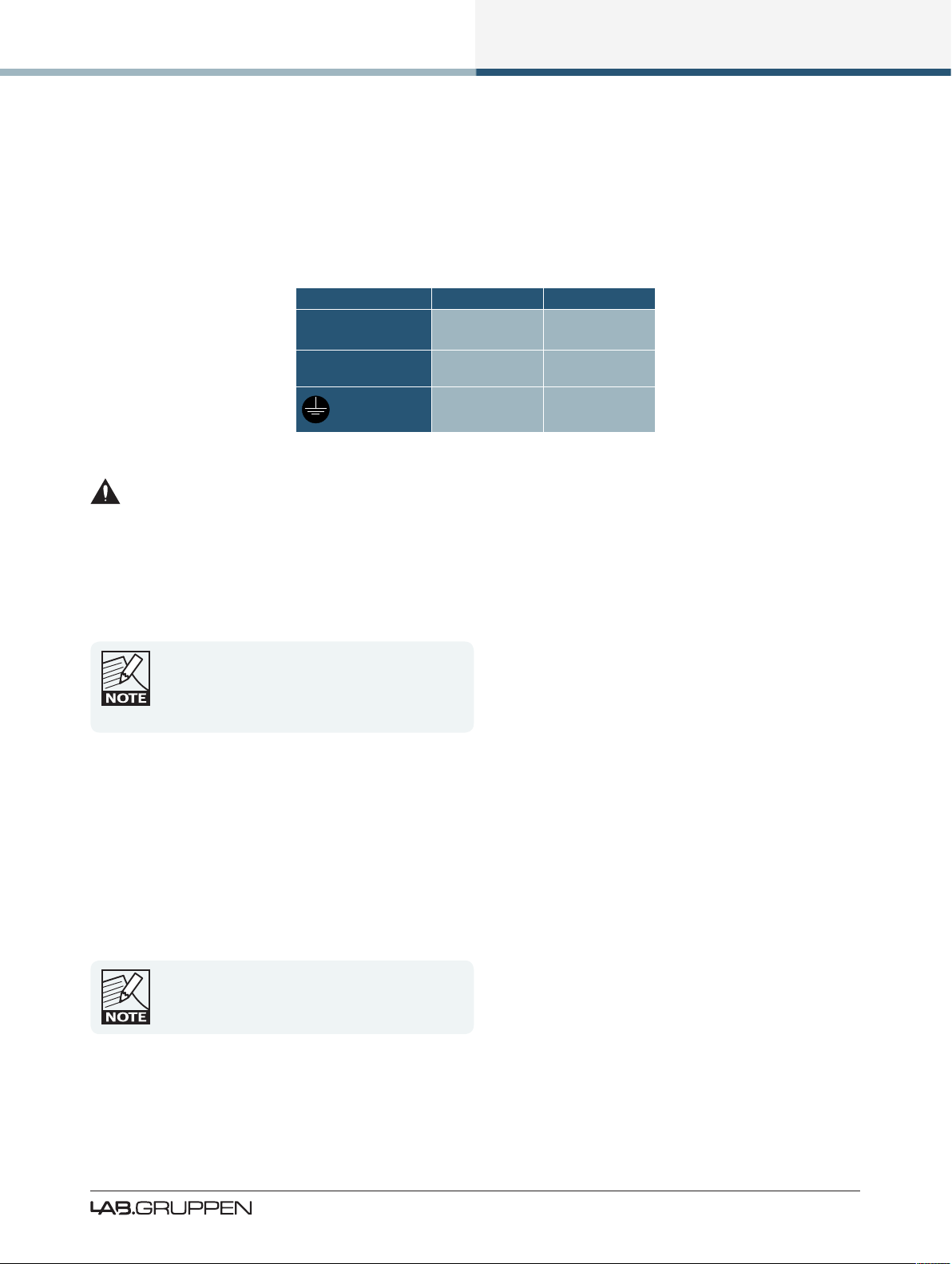
Two mounting methods are possible; note that the method shown in Figure 3-2 additionally provides extra
security against unauthorized removal. For situations where rapid removal and replacement is required, the
method shown in Figure 3-3 should be used.
4
PLM Series Operation Manual rev 1.2.3
Page 11
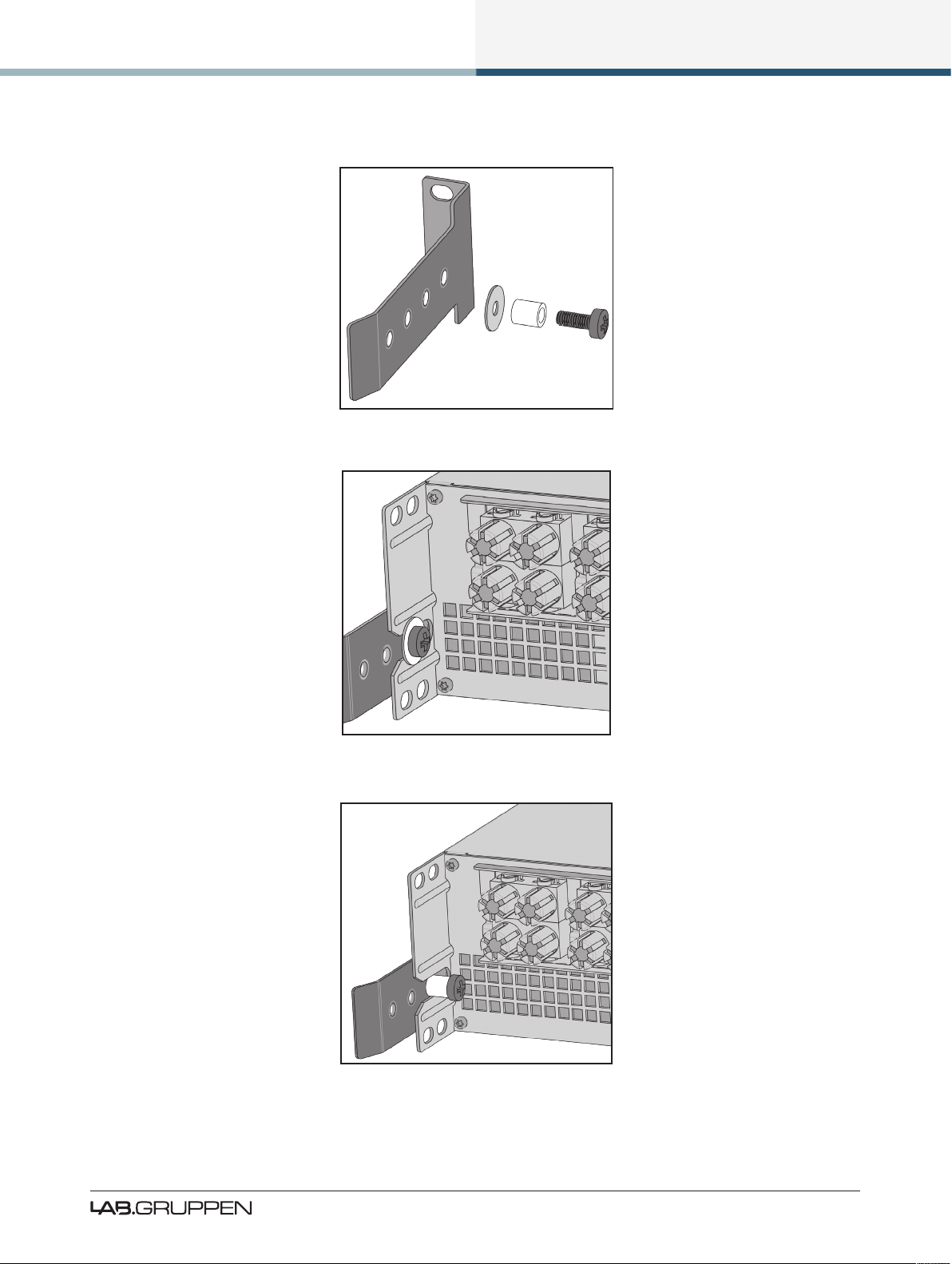
Figure 3-1: Rear Support Bracket and Mounting Hardware
Installation
Figure 3-2: Use the Washer for Fixed Installations
Figure 3-3: Use Tube for Slide-On Installation
PLM Series Operation Manual rev 1.2.3
5
Page 12
Installation
3.3 Cooling
3.3.1 Overview
The PLM Series devices use a forced-air cooling system with airow from front to rear, allowing high
continuous power levels without thermal problems. Front-to-rear airow is preferable as air at the front of
a rack is cooler than that at the rear in nearly all situations; never attempt to reverse the airow. The operation of the PLM’s cooling system is dependent on front-to-rear airow; it will not function effectively with
external airow in the opposite direction.
Make sure an adequate air supply is provided in front of the PLM, and that the rear of the PLM has
sufcient space to allow air to escape. If the PLM is rack-mounted, never operate the unit with any front or
rear rack doors or covers in position. It is recommended to keep the ambient temperature around the PLM
as cool as possible. An increased temperature can have a signicant negative impact on the expected
lifetime on the components inside the PLM.
Fit solid blanks (not ventilation blanks) to unused
rack spaces to ensure effective air circulation.
Leaving gaps in between items of equipment
degrades the effectiveness of forced-air cooling.
If installing one or more PLM Series devices in a rack with other fan-cooled equipment, be sure that all
the other equipment also uses front-to-rear airow for cooling. If this precaution is not observed, there is a
risk of overheating, as units with the reverse airow will be drawing in air which has already been heated by
the PLMs.
3.3.2 Temperature Sensing and Protection
The PLM is equipped with a sophisticated temperature sensing system which protects it from any overheating which may occur as a result of inadequate ventilation.
Always ensure the dust lters behind the detachable front panel are clean to ensure maximum
possible airow.
3.4 Operating Voltage
The label adjacent to the mains (AC) input connector indicates the AC mains voltage for which the
device is wired and approved. The PLM 10000Q and PLM 14000 devices are available in separate 115 V and
230 V versions; the PLM 20000Q is only available with a universal power supply operating from 80 to 265 V.
Only connect the mains cable (AC cord) to an AC source of the voltage shown on the label.
6
PLM Series Operation Manual rev 1.2.3
Page 13
Installation
The PLM uses primary switching, which means the mains power is rectied on the primary side of the
transformer. This makes the power supply insensitive to mains frequency variation, and it will operate
normally on line frequencies from 45 to 75 Hz.
If the mains plug (AC plug) tted to the mains cable (AC cord) is not appropriate for your country, it can be
removed and a locally-sourced one tted instead, observing the color coding in the table below:
powerCON Pin 230 V Version 115 V Version
L Brown Black
N Blue White
Green/ Yellow Green
Table 3-1: AC Plug Conguration
If you are not 100% condent of your competence to replace the mains plug (AC plug), the task should
be carried out by qualied personnel.
Once a suitable AC power supply is connected, the device can be turned on using the front panel power
button. When turned on, a diagnostic routine is performed and the power button LED changes from red
(Standby) to green (Active).
In-rush current is controlled and limited during the
soft-start sequence. This enables multiple PLMs on
the same AC mains circuit to be turned on
simultaneously.
3.5 Grounding
Analog inputs feature Iso-Float™ ground isolation, a technology which combines the benets of transformercoupled isolation with the advantages of clean, direct-coupled inputs.
The audio converters are galvanically isolated, and not connected to the main ground. High-speed transformers and opto-isolators create a barrier between the device and the outside electrical environment.
The Iso-Float feature is activated by default, but
may be disabled via the Lake Controller software,
or via the front panel menu.
PLM Series Operation Manual rev 1.2.3
7
Page 14

Installation
Use correctly-shielded balanced audio input connections to minimise hum and interference. Please refer to
section 8.2.4 for further information.
NEVER disconnect the earth (ground) pin on the mains cable (AC power cord).
8
PLM Series Operation Manual rev 1.2.3
Page 15

Product Overview
4. Product Overview
This chapter provides and overview of key features and functionality. For further information please see
chapters 5 to 10 of this Operation Manual.
4.1 Front Panel Overview
Figure 4-1: PLM Front Panel Overview
The front panel controls are clustered around a daylight readable LCD , allowing adjustment and monitoring of the majority parameters and meters. The two clusters of controls on either side of the LCD include
ve dedicated function buttons , eight dynamic function buttons with embedded LEDs
and a rotary data encoder .
Handles
Two sturdy metal handles are tted to the front panel. The handles should be used when carrying the
device, and when tting it in or removing it from a rack. Ensure that any door or removable rack front cover
has sufcient depth to clear the handles.
Dust Filters
Two dust lters are tted behind metal covers. To remove the covers, loosen the thumbscrews located
behind the handles. Once detached, the dust lter elements can be removed for cleaning; please refer to
section 9.2 for further information.
NEVER operate this device without the dust lters
in place.
PLM Series Operation Manual rev 1.2.3
9
Page 16

Product Overview
Display
The display illuminates when the device is on. The LCD, function buttons, and the rotary encoder provide
real-time control and monitoring of most parameters. The LEDs embedded in the function buttons indicate
available menu options, provide conrmation of Controller communication, and indicate various faults and
warnings.
The brightness and contrast of the display and front panel LEDs can be adjusted via the front panel menu.
Please refer to chapter 7 for further details.
Standby
PLM Series devices are powered on and to standby using the top-left button, or via the Lake Controller.
Mute Enable
Select MUTE ENABLE to allow the dynamic function buttons to operate as mute controls for the Module
inputs and power output channels. The MUTE ENABLE button ashes when the mode is selected; a
subsequent press deselects this mode. If left activated, MUTE ENABLE mode will automatically disable two
minutes after the last mute action.
Meter
The METER button scrolls through four alternative meter views: Home View, Module View, Temperature
View and Input View. Pressing METER from Menu Mode returns the screen to Meter Mode with Home
View displayed. Please refer to section 7.5 for further details.
Menu
After pressing the MENU button, the LCD will display the top level menu. In Menu Mode the function
buttons enable access to various information and functions. Please refer to section 7.6 for further details.
Dynamic Function Buttons with LEDs (Left of LCD)
The function of these buttons change according to the currently selected view or menu.
▸ In Menu Mode they are used for menu navigation and for parameter selection
▸ In Meter Mode they provide Module input mute/unmute functionality in conjunction MUTE ENABLE
The LED in the top button provides Frame fault and warning indications. The middle two buttons provide
Module input mute functionality, mute indication and faults and warning indications relating to the PLM
inputs. The bottom button is used only in Menu Mode or to lock the front panel buttons.
10
PLM Series Operation Manual rev 1.2.3
Page 17

Product Overview
Please refer to chapter 7 for further details.
Dynamic Function Buttons with LEDs (Right of LCD)
The function of these buttons change according to the currently selected view or menu.
▸ In Menu Mode they are used for menu navigation and for parameter selection
▸ In Meter Mode they provide PLM output mute/unmute functionality in conjunction MUTE ENABLE
All LEDs provides mute, clip, fault and warning indications for the PLM power outputs channels.
Please refer to chapter 7 for further details.
Communication LED
The high-intensity white LED illuminates white to indicate that the Module/Frame is selected in the
Lake Controller; it ashes white to indicate communication with the Lake Controller.
The brightness of the LCD and communications LED can be adjusted in the Frame page of the Main Menu
on the front panel.
Rotary Encoder
The rotary encoder is used to modify various parameters (e.g. input level) via the menu. When a menu item
is selected that permits adjustment of parameter values, the ring around the rotary encoder illuminates. In
Home View the encoder can be used to scroll through the Meter Views.
Exit
The EXIT button is used primarily while navigating the menu system in Menu Mode; pressing EXIT will
return the menu up one level. In Meter Mode, pressing EXIT returns the metering display to the default
Home View.
PLM Series Operation Manual rev 1.2.3
11
Page 18
Product Overview
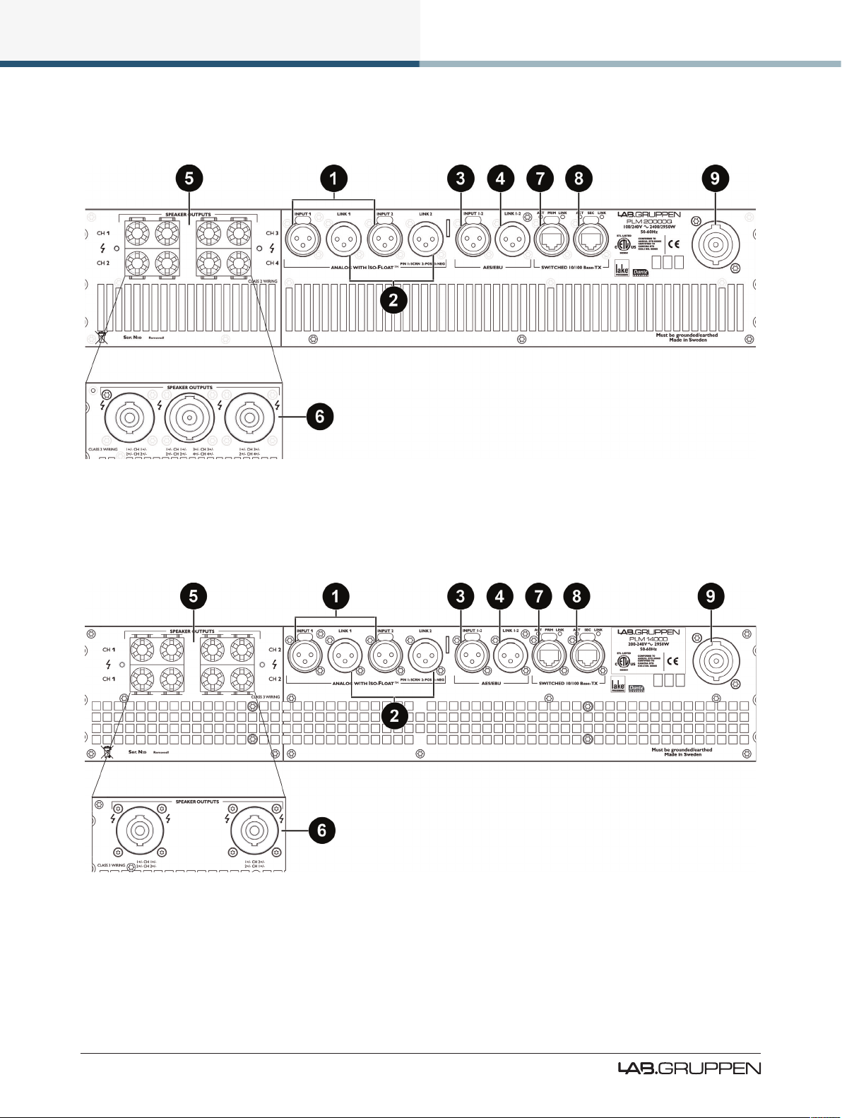
4.2 Back Panel Overview
Figure 4-2: Back Panel Layout Options for a 4-channel PLM
Figure 4-3: Back Panel Layout Options for a 2-channel PLM
12
PLM Series Operation Manual rev 1.2.3
Page 19
Product Overview
4.2.1 Input and Link Connectors
Analog Inputs
Analog inputs are available on two standard XLR3F latching connectors. The inputs are electronically
balanced and feature Lake Iso-Float circuitry. The impedance is 20 kohms, and the inputs can accept a
maximum input level of +26 dBu.
Analog Links
Two latching XLR3M connectors are tted adjacent to the analog input connectors. These are paralleled to
the input connectors to provide an unprocessed analog loop-through to feed additional PLM Series units, or
other equipment.
AES3 Inputs
A latching XLR3F connector is provided which accepts an AES3 digital audio signal. Input impedance is 110
ohms, please ensure that 110 ohm digital audio cables are used; standard XLR microphone cables are rarely
suitable for reliable digital audio transmission.
AES3 is a stereo digital format, and therefore both
PLM inputs are fed via a single connector. Selection
of the analog or digital inputs is made via the front
panel display or control software.
AES3 Link
A latching XLR3M connector is tted adjacent to the AES3 input connector. This is paralleled to the input
connector to provide an unprocessed AES3 loop-thru to feed further PLMs, or other equipment. An AES3
110 ohm termination load is enabled by default when the PLM is the last unit connected within an AES3
daisy-chained system. The termination may be disabled, if desired, via the front panel menu and within the
Lake Controller software.
4.2.2 Output Connectors
The PLM is available with a choice of connectors for power outputs: binding posts or Neutrik speakON®.
Both connection methods allow for Bridge Mode operation, which is activated from the Lake Controller
software. Please refer to the Lake Controller Operation Manual and section 8.1.1 of this Operation Manual
for further information on Bridge Mode.
PLM Series Operation Manual rev 1.2.3
13
Page 20

Product Overview
Binding Posts
In this version, the power outputs for loudspeaker connection are available on four separate pairs of fully
enclosed binding posts. Bridge Mode can be enabled via the Lake Controller software, please refer to the
Lake Controller Operation Manual for further information.
Channel conguration for the binding posts is dependent on the PLM model, please refer to section 8.1.3 of
this Operation Manual for standard and Bridge Mode wiring.
speakON Connectors
The speakON connector conguration differs on 2-channel and 4-channel PLM models.
On 4-channel models, the power outputs are simultaneously available on a single 8-pole speakON connector, and on two 4-pole speakON connectors. The two 4-pole connectors carry the outputs of channels 1 & 2
and 3 & 4 respectively.
On 2-channel PLM models the two power output channels are available simultaneously on two 4-pole
speakON connectors. Both connectors carry both channels. The second connector offers the channels in
reverse order.
Bridge Mode can be enabled via the Lake Controller software, please refer to the Lake Controller Operation
Manual and to section 8.1.2 of this Operation Manual for further details on standard and Bridge Mode wiring
for speakON connectors.
4.2.3 Ethernet and Power Connectors
Primary Network Connector
The primary Neutrik RJ45 etherCON® connection provides integration into an Ethernet control network
which may include other Lake Processors and the Lake Controller software. Network connection permits full
control of all functions along with real-time metering from a remote position. This device supports the Dante
audio networking protocol, which allows transmission of multichannel, high-denition digital audio over the
same Ethernet connection.
Use the primary connector when using a star network topology, consisting of individual Cat-5e connections
between the devices and an Ethernet switch. Alternatively this connection can be used to daisy chain
directly to another Lake Processor. The daisy chain topology should not be used with Dante.
For a technical reference of the Ethernet Port, please refer to section 8.4. Additional information is available
in the Lake Network Conguration Guide.
14
PLM Series Operation Manual rev 1.2.3
Page 21
Product Overview
The Ethernet ports operate at the Ethernet data rate of 100 Mbps, and
allow straight or crossed network cables. Two LEDs above each port
indicate valid network connection (LINK) and network activity (ACT).
Secondary Connector
The secondary network connector can be used to daisy-chain multiple PLM Series, LM 26 and legacy Lake
devices. Alternatively, a Dante dual-network topology can be created by connecting all secondary network
connectors to a separate Ethernet switch, ensuring full redundancy in the event of a network component
failure.
Additional processor conguration is required for a
dual redundant network setup. See the Lake
Controller Operation Manual for further details.
For a technical reference of the Ethernet Port, please refer to section 8.4. Additional information is available
in the Lake Network Conguration Guide.
When connecting multiple devices to an Ethernet
network, care must be taken NOT to create a
closed loop which causes network malfunction.
Mains Power Connector
The mains power AC input is via a Neutrik powerCON connector, rated at 32 A.
The power supply must be connected to AC mains using a power cable with a correctly wired plug for the
country of operation.
PLM Series Operation Manual rev 1.2.3
15
Page 22
Operation and Performance
5. Operation and Performance
This chapter provides comprehensive information on PLM Series connection, setup, operation and performance. The detailed information included here is essential to realizing the full functionality of the PLM Series
devices.
5.1 Operation Precautions
Make sure that the Standby button on the PLM’s front panel is either unlit (OFF), or red (STANDBY), before
making any input or output connections.
Ensure the AC voltage matches that printed on the label adjacent to the AC mains connector.
Ensure no input signal is present when powering on the PLM to reduce the risk of any inadvertent bursts of
high level audio.
5.2 Power Output Performance
The PLM uses Lab.gruppen’s patented Class TD technology in the output stages, which couples the efciency of Class D topologies to the sonic purity of Class B designs.
The primary benet is that Lab.gruppen’s Class TD works perfectly under all load conditions. The output
maintains its at frequency response even into complex loads with very low nominal impedances. Reliability
is very high, and there is no interference with nearby RF equipment. Superior efciency allows greater
power density while minimizing cooling requirements, yet sound quality matches that of the best Class B
designs.
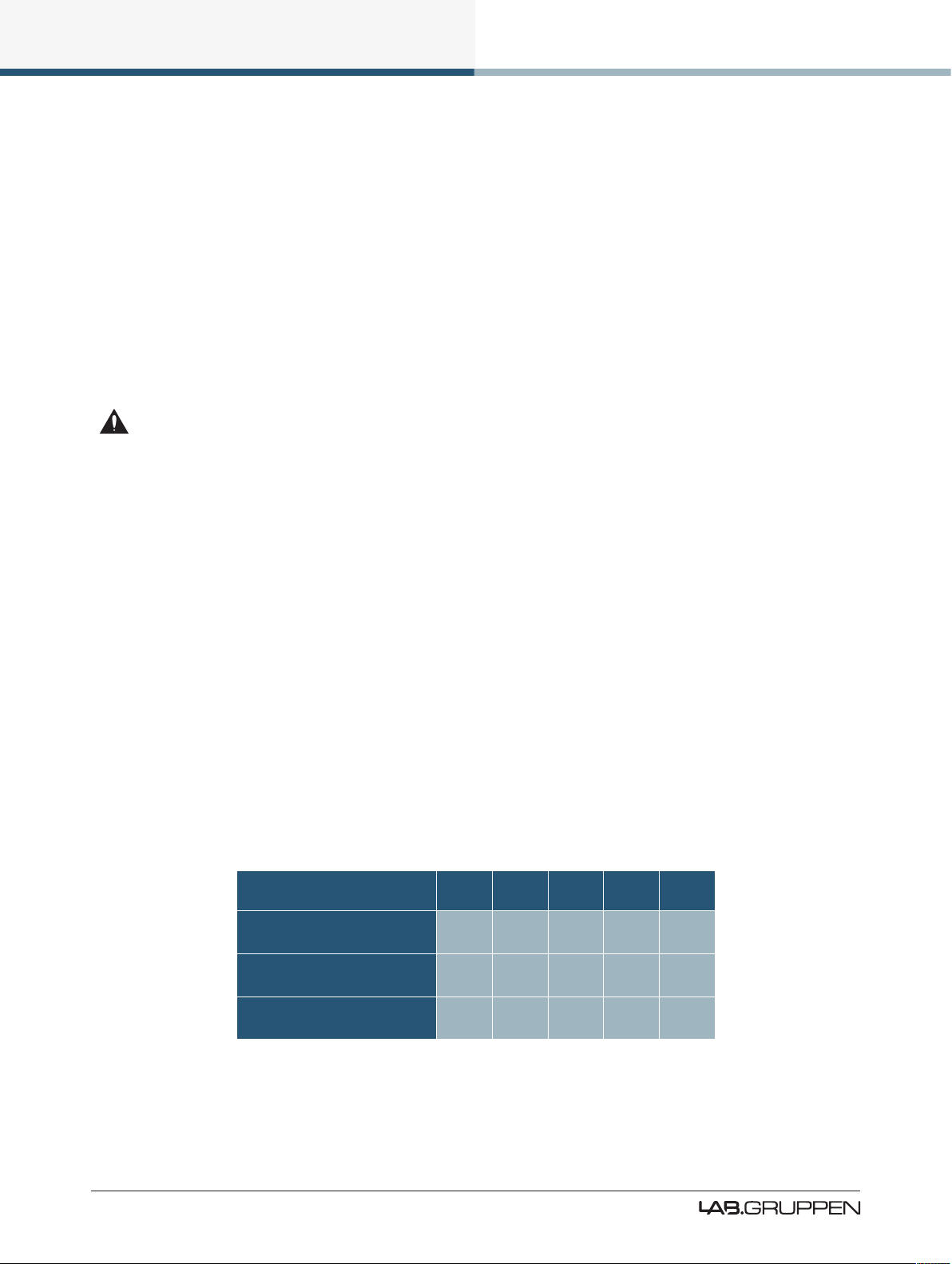
5.2.1 Symmetrical Power
The PLM models can deliver power as shown in Table 5-1 when all channels are driven equally.
Load Impedance (ohms) 2.0 2.7 4 8 16
PLM 10000Q
Max. Output power (Watts)
PLM 14000
Max. Output power (Watts)
PLM 20000Q
Max. Output power (Watts)
2350 2700 2300 1300 660
7000 6000 4300 2300 1150
4800 5000 4440 2300 1150
16
PLM Series Operation Manual rev 1.2.3
Table 5-1: Symmetrical Load Power Ratings
Page 23
Operation and Performance
5.2.2 Asymmetrical Power
The PLM models can deliver power as shown in Table 5-2 when every other channel is driven 3 dB lower
than the other. This can occur when the load on the individual power output channels within the amplier
contain different frequency ranges.
Load Impedance (ohms) 2.0 2.7 4 8 16
PLM 10000Q
Max. Output power (Watts)
PLM 14000
Max. Output power (Watts)
PLM 20000Q
Max. Output power (Watts)
Table 5-2: Asymmetrical Load Power Ratings
2350 2900 2400 1300 660
7500 6300 4400 2300 1150
5000 5550 4500 2300 1150
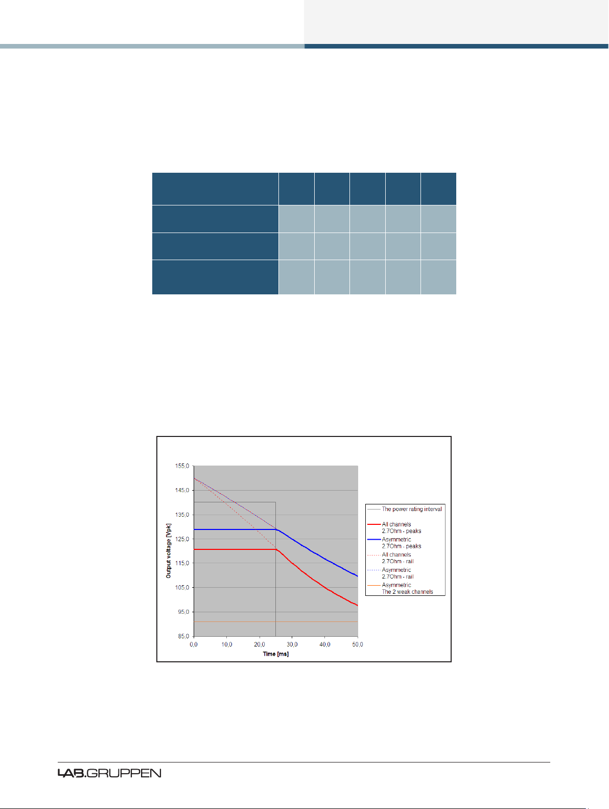
5.2.3 Power Over Time
Power ratings given above are applicable for PLMs running at these levels for a period of 60 minutes. Due
to thermal considerations in the power supply and elsewhere, it is possible to draw higher power levels for
a shorter period of time. The graph below illustrates, for the example PLM 10000Q, how the rated power
gures are derived and the higher short-term capability.
Peak output voltage at “max power burst”
Figure 5-1: Power Rating Levels Over Time (PLM 10000Q)
Power ratings are based on a duty cycle of 25 ms full power every 400 ms. Between bursts, a lower signal
level applies, such that the continuous average power is 1/8th of the rated power.
PLM Series Operation Manual rev 1.2.3
17
Page 24

Operation and Performance
In reality, when some channels are delivering less than maximum rated power, energy reserves in the PSU
are available to permit other channels to deliver more power. The graph shows the peak output voltage over
time for a continuous sine wave is applied.
If all four channels are driven with the same signal into the same impedance (solid red line), then the rail
voltage (dotted red line) will drop faster than when two channels are delivering maximum power (solid blue
line) and two channels are delivering half-power (solid orange line). This is termed asymmetric loading; the
rail voltage for this is indicated by the dotted blue line.
It can be seen that higher power output is available for 25 ms bursts with asymmetric loading.
5.3 Amplier and Load Protection Systems
The PLM is equipped with a comprehensive set of protection circuits. If operating conditions become sufciently extreme that any of these circuits become active, indication is provided by LEDs in one or more soft
function buttons 5-8, together with adjacent warning text. In addition to this, notication is also presented
within the Lake Controller software and within system log les.
5.3.1 Inter-Sample Voltage Peak Limiter (ISVPL)
The ISVPL is a high quality voltage limiter that can deliver seamless limitation to any desired level. Its
ensures that the voltage at the output terminals never exceeds the dened threshold.
It operates on these principles:
▸ The signal is delayed slightly to allow the ISVPL to look-ahead and reduce the gain before voltage in
excess of the threshold can appear at the output. This results in zero voltage overshoot at the output
with a rounded limitation up to the threshold.
▸ The amplitude of the output signal between digital samples is predicted which permits the ISVPL to
respond to analog peaks that may occur at the digital to analog converter.
▸ The release time of gain reduction is adaptive depending on the dynamics of the signal.
It is possible to select different ISVPL proles for limiting optimization for a specic frequency band and
personal preference. The proles are divided into two categories, with one category optimized for low
distortion and the other focusing on producing high sound pressure level (SPL). Within each category there
are proles optimized for the different frequency bands.
5.3.1.1 Low Distortion Proles
▸ Universal – The universal prole is a soft limiter that can be used for all frequencies and is conservative
in its action upon VCL and CPL.
▸ Sub/LF – The Sub/LF prole is tuned for frequency bands below 600Hz. It has longer attack and release
times and is less conservative when it comes to acting upon VCL and CPL.
18
PLM Series Operation Manual rev 1.2.3
Page 25
Operation and Performance
5.3.1.2 High SPL Proles
High SPL proles do not use the adaptive release time feature. High SPL proles optimized for high frequencies use less of the look-ahead delay peak-rounding feature; this feature is used most in the Sub prole and
least the HF prole.
▸ Sub - The Sub prole is optimized for frequencies between 20 - 200 Hz
▸ LF - The LF prole is optimized for frequencies between 20 - 1200 Hz
▸ MF - The MF prole is optimized for frequencies between 300 - 6000 Hz
▸ HF - The HF prole is optimized for frequencies above 1 kHz
Table 5-3 shows the theoretical maximum output power for a given load impedance and ISVPL setting.
An ISVPL-to-load calculator that will assist in generating the
appropriate ISVPL setting for a desired power load is available
at www.labgruppen.com/plm
MAX. SINEWAVE BURST POWER (Watts)
Load Impedance (ohms)
ISVPL SETTING (V
194 9409 7048 4705 2352 1176
193 9312 6984 4656 2328 1164
181 8190 6143 4095 2048 1024
167 6972 5229 3486 1743 872
153 5852 4389 2926 1463 732
121 3660 2745 1830 915 458
101 2550 1913 1275 638 319
83 1722 1292 861 431 215
70 1225 919 613 306 153
56 784 588 392 196 98
47 552 414 276 138 69
38 361 271 181 90 45
17.8 79 59 40 20 10
peak)
2 2.67 4 8 16
Table 5-3: ISVPL-to-output examples
These ratings shown in Table 5-3 are limited by the
CPL (Current Peak Limiter) functions, not by ISVPL
settings, due to power output channel current
capacity.
PLM Series Operation Manual rev 1.2.3
19
Page 26

Operation and Performance
The ISVPL threshold may be set at any level between 17.8 V and 600 V via the PLM’s menu system. For
further details, please refer to section 7.11.2.5 of this manual, and also to the PLM Series chapter in the
Lake Controller User Manual.
PLM devices that have a smaller peak output voltage can still set the ISVPL threshold up to 600 V. When
a threshold is set above the maximum capability of a power output channel, the maximum ISVPL for that
product will be automatically set. Therefore, the ISVPL threshold can be in at the Module for the speaker’s
maximum capability, and the Module le remains cross-compatible with all PLM Series devices.
5.3.2 Current Peak Limiter (CPL)
The output Current Peak Limiter (CPL) ensures that the power output section will not be damaged by forcing
it to deliver current levels at the outputs that exceed the maximum current ratings of the output transistors.
The CPL keeps the output transistors within their Safe Operating Area (SOA). The CPL is non-adjustable.
CPL activity is indicated on the power output channel LED (embedded in the associated output channel’s
function button to the right of the LCD). Activity on an affected channel results in a ashing red indication
together with a CURRENT CLIP warning message displayed on the screen adjacent to the LED. A warning is
also displayed on the controlling PC via the network.
This condition indicates an attempt to draw excessive current at the output. The output is attenuated until
the output current falls below the maximum current rating. Limiting is performed by the ISVPL limiter in
conjunction with the selected ISVPL prole. Please refer to the Technical Specications in chapter 11 for
further details regarding ratings.
If excessive current is indicated, check the output cables and examine the
loudspeaker. If impedance appears normal, you may rectify the condition by
altering the ISVPL settings or lowering input levels. CPL indication can be
triggered by excessively low output impedance, possibly the result of too
many loudspeaker cabinets connected in parallel.
5.3.3 Power Average Limiter (PAL)
5.3.3.1 PLM 10000Q and PLM 14000
The Power Average Limiter (PAL) controls the AC current into the power supply. Power consumption is
limited to the rated design parameters of the power supply, ensuring that the PSU will never be overloaded.
Also, high-power products such as those in the PLM Series can potentially draw more current (with output
devices still within safe operating areas) than is allowed by the external mains breaker.
The PAL protection feature can help prevent the supply’s external breaker from tripping within time intervals
of less than three minutes. For longer time intervals, it is the responsibility of the user to ensure that the
average level of the audio is within limits that ensure that the breaker doesn’t trip.
20
PLM Series Operation Manual rev 1.2.3
Page 27

Operation and Performance
PAL activity is indicated by the LED within the rst soft button adjacent to the display ashing red,
together with a PAL ACTIVE warning message displayed on the screen. A warning is also displayed on the
Lake Controller software.
5.3.3.2 PLM 20000Q
The Power Average Limiter Active warning (PAL Active) will be displayed when the power supply’s maximum rated design parameters are reached. When this warning is displayed, gain limiting is being applied to
the signal and the ISVPL threshold is lowered accordingly.
5.3.4 Breaker Emulation Limiter (BEL™)
The Breaker Emulation Limiter feature is present only in the PLM 20000Q. The PLM 20000Q is a powerful device that can draw a considerable amount of current from the mains supply. The BEL models the
temperature in the external breaker and limits the mains current to prevent it from tripping. The BEL can be
congured with both a breaker prole and a current value. The current value can be set from 5 to 32 Arms.
There are three different proles available for selection:
▸ Conservative - The conservative prole allows no momentary current above the congured threshold.
▸ Fast - The fast prole models the time constant of the trip-curve corresponding to a fast breaker. It
momentarily allows current above the threshold to pass for a short time, leading to an increased modeled temperature. For the limiter to disengage, the current must reduce below the threshold to enable
the breaker to cool down.
▸ Universal - The universal prole models the time constant of the tripp-curve corresponding to a slow
breaker. It momentarily allows current above the threshold for a longer time, leading to an increased
modeled temperature. For the limiter to disengage the current has to reduce below the congured
current for the breaker to cool down.
The BEL can be congured via the PLM front panel and via the Lake Controller.
5.3.5 Under Voltage Limiter (UVL™)
The PLM 20000Q is equipped with an under voltage limiter. With mulitple powerful devices on a mains
distribution line, heavy current loads risk the reduction of voltage below that required for devices to function.
The PLM 20000Q’s UVL reduces the mains current draw when voltage drop below 80 V. The amount of
reduction applied increases as mains voltage drops towards 65 V, then at 65 V the power supply is shut
down. The mains supply is continually monitored and when sufcient voltage returns the power supply
automatically restarts.
PLM Series Operation Manual rev 1.2.3
21
Page 28

Operation and Performance
5.3.6 Current Average Limiter (CAL™)
The Current Average Limiter (CAL) monitors the RMS current drawn from each power output channel
to ensure that the power output stages are not overloaded. When activated, it regulates the current to a
safe level to protect the channel. The CAL should not be activated in normal usage, but if it is, its operation is indicated by an active LED and the message CAL ACTIVE. Further indication is given within the
Lake Controller software.
5.3.7 Voltage Clip Limiter (VCL)
If current draw from the PLM’s power supply is too high, the PSU’s regulation capability may be exceeded
and the internal voltage rails may drop and cause clipping. If this occurs the VCL acts rapidly to prevent clipping on the subsequent peaks. Limiting is performed by the ISVPL limiter in conjunction with the selected
ISVPL prole. Indication of this condition is shown on the output LEDs.
5.3.8 Temperature Protection
5.3.8.1 Overview
PLM Series devices are equipped with a sophisticated temperature sensing system that provides protection
from overheating which may occur as a result of inadequate ventilation or excessive power output.
Thermal measurements are made at several points within each power output channel along with measurements in the power supply and DSP areas. If temperature in any area reaches a critical level then a warning
is displayed and gain reduction is applied. If the temperature continues to increase and reaches a dangerous
level then a fault is displayed and audio is muted. Each power output channel, the power supply and DSP
area have separate indications.
For all temperature faults, temperature monitoring will continue at 0.5 second intervals, with the output
remaining muted. When the area has cooled below the dangerous threshold, the fault condition is cleared
and audio is restored.
5.3.8.2 Power Output Channels
A power output channel temperature warning or fault is indicated in one of the front panels LEDs (in the
right-hand soft function buttons).
▸ A warning is indicated by a static yellow LED and adjacent warning message: TEMP WARN:CH
▸ A fault is indicated with a static red LED and adjacent warning message: TEMP FLT:CH
An event report is sent to the Lake Controller software for both the warning and the fault. If a temperature
fault condition arises on a power channel, the output of that channel will be muted.
22
PLM Series Operation Manual rev 1.2.3
Page 29

Operation and Performance
5.3.8.3 Power Supply / DSP
A power supply (PSU) or DSP temperature warning or fault is indicated by the LED in the top-left function
button.
▸ A warning is indicated by a static yellow LED and adjacent warning message: TEMP WARN:PSU
(or TEMP WARN:DSP)
▸ A fault is indicated with a static red LED and adjacent warning message: TEMP FLT:PSU
(or TEMP FLT:DSP)
An event report is sent to the Lake Controller software for both the warning and the fault. If a temperature
fault condition arises in the power supply the output of all channels will be muted. If a temperature fault
condition arises in DSP area, audio will not be muted but continued operation is not recommended.
5.3.8.4 PLM 20000Q
For the PLM 20000Q a temperature dependant limiting feature is also present. At temperatures above the
critical warning level and below the dangerous fault level, the ISVPL threshold is slowly reduced to decrease
the output power and cool down the device. This enables the device to continue to pass audio, although
with a reduced amplitude, in extreme conditions. If reducing the ISVPL threshold does not cool down the
device a temp fault will still be issued when the dangerous temperature level is reached.
5.3.9 DC Protection
DC protection is implemented on each power output to prevent damage to connected loudspeakers or any
PLM components. DC present at the output will cause the PLM’s power output module breaker to blow. In
this instance a red LED will illuminate and NEEDS SERVICE will display on the LCD.
The power output channel modules are independent of
the input voltage. Both 115 and 230 V models have amp
channel fuses. This is not a user-servicable fault
condition and the unit should be returned for repair.
5.3.10 VHF Protection
The PLM includes protection circuits that detect Very High Frequency (VHF) content in the input signal. The
detection is frequency-dependent, initiated from 10 kHz upwards. If VHF signals are detected above the
threshold, the output will mute for approximately 6 seconds before a further measurement is taken. When
continuous VHF signal stops, the output unmutes and the amplier returns to normal operation.
This protection system recognizes that continuous VHF signals at high levels do not appear in speech or
music. Any such content can therefore be considered as a fault condition. VHF protection is essential to
avoid damage to HF drivers.
PLM Series Operation Manual rev 1.2.3
23
Page 30
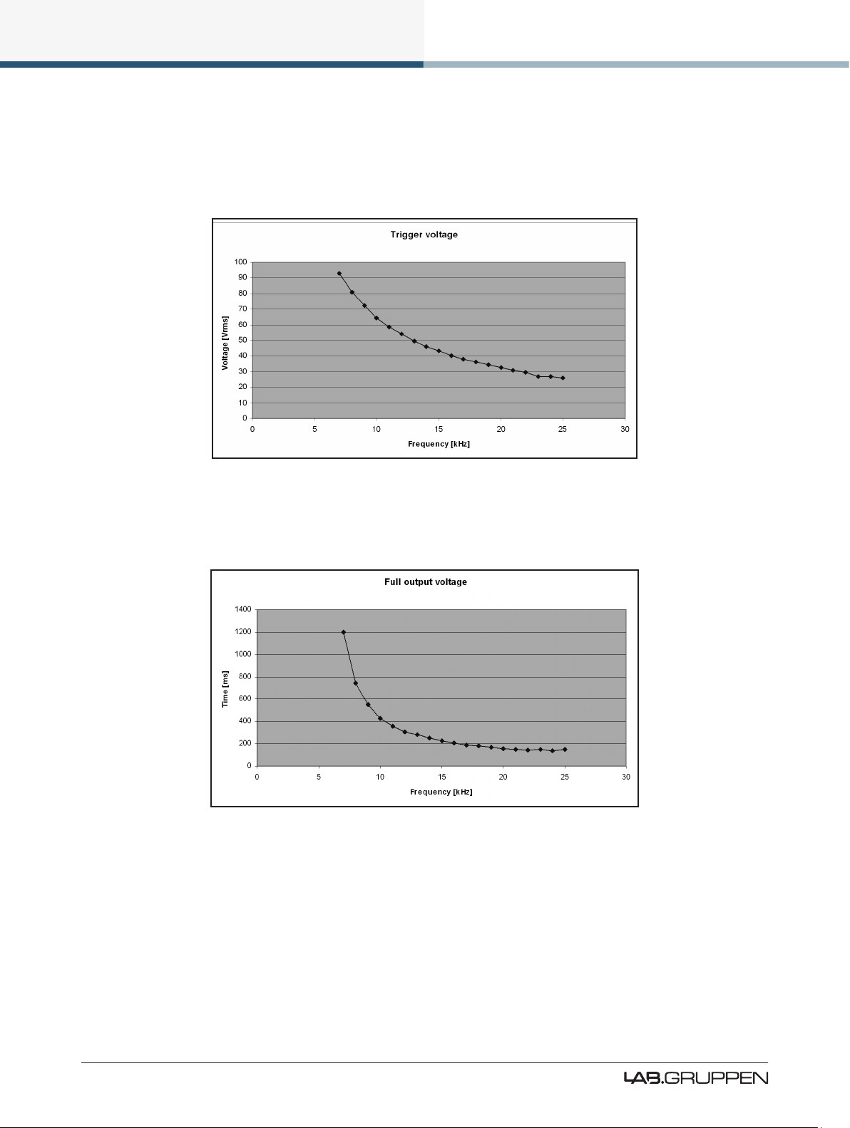
Operation and Performance
VHF protection is dependent on a combination of output power level and frequency. Figure 5-2 shows a
decreasing power threshold, from approximately 10 kHz upwards, which illustrates increasing sensitivity of
the protection system with frequency. When continuous output power above the threshold line is detected,
VHF protection becomes active.
Figure 5-2: VHF Protection Frequency Sensitivity
The attack time of the VHF protection circuitry also changes with frequency, becoming shorter at higher
frequencies. This is shown in Figure 5-3.
Figure 5-3: VHF Protection Attack Time Variations
The VHF protection circuit is NOT a limiter and does not alter the PLM’s frequency response. It is implemented solely to detect continuous VHF content. HF content of normal music or speech signals at peak
levels will be passed in full.
Operation of the VHF protection circuits is indicated by one (or more) of the output channel LEDs (in the
right-hand soft function buttons) showing steady red. The adjacent fault message will show VHF FAULT. It is
also reported as a fault via the control network.
24
PLM Series Operation Manual rev 1.2.3
Page 31

Operation and Performance
5.3.11 Short Circuit Protection
A low impedance or short circuit at the power output terminals is detected when the output current is high
(Current Peak Limiter is active) and, simultaneously, the peak output voltage is below a predetermined
threshold (42 V with the PLM 10000Q, for example). When this situation occurs, the output stage is muted
to protect it from damage. Operation of the short circuit protection system is indicated by an output channel
LED (in the right-hand soft function buttons) showing steady red. The adjacent fault message will show
SHORT CIRCUIT. It is also reported as a fault via the control network to the Lake Controller software. The
presence of a short circuit (or low impedance) is re-tested every six seconds, and the output remains muted
until the fault clears.
5.4 Power Supply
The R.SMPS (Regulated Switch Mode Power Supply) is designed to keep supply voltage rails at optimum
levels even when the mains voltage drops. Mains voltages can drop as much as 20% below nominal before
there is any effect on rail voltages. Thus the R.SMPS can deliver full rail voltage to the output stage at all
times, allowing the PLM to exhibit consistent transient response and a clean LF response.
The PLM 20000Q is also equipped with a universal power supply with power factor correction (PFC). The
device can take any mains voltage, from 65 V to 265 V, allowing it to function worldwide in many different
congurations. The PFC reduces current peaks on the lines and reduces the requirements placed on the
mains distribution system. The PLM 20000Q has an unparalleled power factor extremely close to one.
5.4.1 Low Inrush Current
High power ampliers with inadequate inrush current limiting can draw considerable current from the mains
at turn-on, sometimes tripping a fast-acting mains breaker. The PLM, however, has very low inrush current
(the capacitors charge slowly and in a controlled manner) to prevent tripping of breakers.
Several PLMs can, under normal conditions, be powered up simultaneously. If you do experience problems
powering up multiple PLMs simultaneously, they must either be turned on manually in an ordered manner,
or sequenced remotely using the Lake Controller software’s Global Control feature. Alternatively, the capacity of the mains supply should be increased.
If insufcient power is available to allow simultaneous power-up, then there is probably insufcient
capacity for full power output during operation. It is
recommended that additional capacity is added to
the mains power distribution system.
PLM Series Operation Manual rev 1.2.3
25
Page 32

Signal Flow and Lake® Processing
6. Signal Flow and Lake® Processing
6.1 Signal Flow
Figure 6-1 and Figure 6-2 depict the audio signal ow inside a PLM. It is worth noting that this sophisticated
device provides seven points in the signal chain where the signal level can be adjusted, muted or disconnected.
Important information regarding correct setting of the gain structure can be found in section 10.3.
Figure 6-1: Signal Flow Diagram (PLM Series Part 1)
6.1.1 Level Adjustments & Mute Points
Input Router Stage - Input selection and MUTE
Input Mixer Stage - Router ON/OFF connection to mixer and gain settings
Module Input Stage - Mute and gain settings
Module Output Stage - Mute and gain settings
Output Router Stage - Output ON/OFF routing connections
26
PLM Series Operation Manual rev 1.2.3
Page 33

Signal Flow and Lake® Processing
Attenuation Stage - Power output channel mute and attenuation settings
Amp Gain Stage - Amplier gain control
If the required audio signal is not passing correctly,
verify the connection, mute and volume settings at
all seven stages.
6.1.2 Power Output Section: Limiting and Sensitivity
The Current Peak Limiter (CPL) dynamically limits the drive to the power stage based on three parameters:
sensed output current level, feedback from the output stage, and sensed voltage clip from the ISVPL. This
ensures that power output is maintained within the design limits of the PLM.
The adjustable Inter-Sample Voltage Peak Limiter (ISVPL) sets the PLM’s maximum output voltage and
therefore also the maximum output power. The ISVPL setting is made via MENU > MODULE > LIMITERS
> ISVPL, and can also be set from the Lake Controller software.
Figure 6-2: Signal Flow Diagram (4-channel PLM Part 2)
The sophisticated output section monitors faults and generates warnings when appropriate; warnings are
displayed on the front panel of the PLM and also sent as messages over the control network. In the rare
event that maximum ratings are signicantly exceeded, the PLM will shut down until the condition has
PLM Series Operation Manual rev 1.2.3
27
Page 34

Signal Flow and Lake® Processing
been rectied or the incorrect setting has been readjusted. Sensing circuits also transmit local output power
stage temperature, processor card temperature, and PSU temperature to the appropriate protection circuits.
Please refer to section 5.3 on page 18 further details.
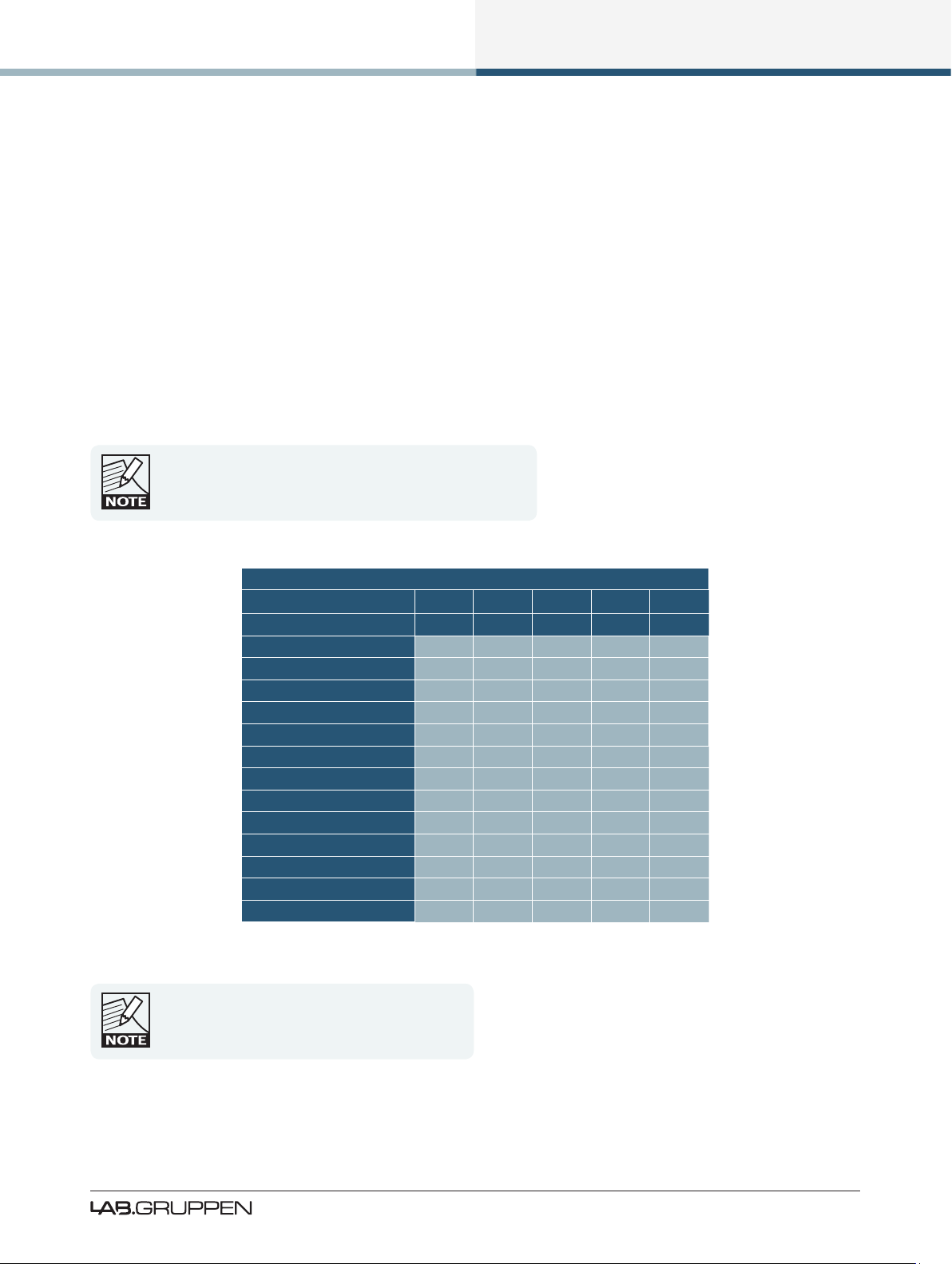
Table 6-1 lists PLM Series analog input sensitivity in dBu and Vrms for various Amp Gain settings and
maximum/minimum ISVPL settings, assuming an analog input headroom of 26 dBu.
ISVPL SETTING 194 V 193 V 153 V 17.8 V
GAIN (dB) dBu Vrms dBu Vrms dBu Vrms dBu Vrms
+44
+41
+38
+35
+32
+29
+26
+22
+1.0 0.87 +0.9 0.86 -1.1 0.68 -19.8 0,08
+4.0 1.22 +3.9 1.22 +1.9 0.96 -16.8 0.11
+7.0 1.73 +6.9 1.72 +4.9 1.36 -13.8 0.16
+10.0 2.44 +9.9 2.43 +7.9 1.92 -10.8 0.22
+13.0 3.45 +12.9 3.43 +10.9 2.71 -7.8 0.32
+16.0 4.87 +15.9 4.84 +13.9 3.84 -4.8 0.45
+19.0 6.88 +18.9 6.84 +16.9 5.42 -1.8 0.63
+23.0 10.90 +22.9 10.8 4 +20.9 8.59 +2.2 1.00
INPUT SENSITIVIT Y
Table 6-1: Analog Input Sensitivity in dBu and Vrms
6.2 Lake Processing and Control
As outlined in section 2.2.3, this device integrates seamlessly into the Lake Processing environment,
providing all features, functionality and connectivity associated with all Lake Processors. The internal Lake
Processing includes programmable crossovers, EQ, dynamics and other functions, and can be fully controlled via the supplied Lake Controller software. Additionally, many functions can be controlled or accessed
directly via the front panel.
The Lake Controller Operation Manual and Lake Network Conguration Guide are supplied on the accompanying CD-ROM and additional documentation is available from the Start Menu after software installation.
6.3 Modules and Frames
6.3.1 Overview
A Frame represents one physical Lake Processor (e.g. a PLM or LM 26). A maximum of two Modules are
contained within each Frame; these are referred to as Module A and Module B. The number of Modules
shown in a given Frame is dependent upon the signal processing conguration of that Frame.
Each Module can be congured as a Classic Crossover (Bessel, Butterworth, Linkwitz-Riley), as a Linear
Phase Crossover, or as multiple full bandwidth Auxiliary Outputs. The default conguration for the PLM is
2 x 2-Auxiliary Output Modules, providing a total of four module outputs.
28
PLM Series Operation Manual rev 1.2.3
Page 35

Signal Flow and Lake® Processing
Please refer to the Lake Controller Operation Manual for further information.
6.3.2 LoadLibrary™ and Fingerprints
In addition to the standard loudspeaker presets (Module les), the Lake Controller also includes a set of
enhanced Module les specically for use with the PLM Series.
These supplementary PLM Module les, known as the LoadLibrary incorporate both Lake DSP parameters
along with PLM specic data; LoadLibrary Module les include parameter settings for the PLM’s Amplier
Gain and ISVPL limiter. Additionally, LoadLibrary loudspeaker types may also include data relating to the
electrical characteristics of a particular loudspeaker.
Electrical characteristic data is used to enable load verication (LoadSmart) and monitoring facilities
(SpeakerSafe) to be performed on the PLM. This data set is termed a Fingerprint. When a PLM-specic
loudspeaker type is loaded, its Fingerprint load characteristics are included. These load characteristics are
stored in a le with a “.mdl” sufx and are loaded simultaneously with the module le.
LoadLibrary Modules and standard Module les are cross-compatible, although when a LoadLibrary Module
is loaded into a legacy Lake product the extra data within it is ignored.
6.3.3 Super Modules
Super Modules allow control of multiple Modules of the same type, distributed across multiple Frames, as
a single entity within the Lake Controller software. A change made in the Super Module is replicated across
all assigned Modules, resulting in improved efciency in system conguration and a reduction of on-screen
icons within the Lake Controller software.
The key benet of this feature is the ability to connect and control crossovers, levels and EQ across multiple
hardware devices simultaneously from the Lake Controller. For example, one device may be driving sub and
low-frequency speakers, while another device controls mid-range and hi-frequency drivers. Using a single
adjustment the crossover points between the two devices can be changed simultaneously.
Please refer to the Lake Controller Operation Manual for further information regarding Super Modules.
6.4 Loudspeaker Crossover Conguration Overview
The Lake Processing system within PLM Series devices may be congured with up to two inputs and up
to six Module outputs, although the number of power outputs will be either two or four depending on the
PLM model being used. To make use of the extra processing channels, multiple hardware devices may be
connected together using the Super Module feature as summarized in section 6.3.3.
Each set of processing elements is referred to as a Module and can be congured as crossovers, fullbandwidth auxiliary outputs, or a combination of the two. The relationship between inputs and outputs is
dened via the Lake Controller or via the front panel Input Cong Menu.
PLM Series Operation Manual rev 1.2.3
29
Page 36

Signal Flow and Lake® Processing
The Lake Processing system provides two distinct categories of crossovers:
▸ Innite Impulse Response lters (IIR) such as the classic Bessel, Butterworth or Linkwitz-Riley types;
these are available with slopes ranging from 6 dB/octave to 48 dB/octave.
▸ Finite Impulse Response lters (FIR) providing zero phase shift with steep transition slopes at the
crossover frequencies. These are also referred to as Linear Phase Crossovers.
Further details on these types of crossovers and information on conguring various module types can be
found in the Lake Controller Operation Manual.
6.5 Files and Presets
The Lake system provides various methods for storing and recalling Module, Frame, or system-wide data. A
overview is provided below; for further information please refer to the Lake Controller Operation Manual.
6.5.1 Module, System and Sub-System Conguration Files
Module, System and Sub-System Conguration les are stored on the Lake Controller PC, and data is
passed across the network when recalling or storing these type of les.
▸ A Module le is the smallest set of data that can be stored and recalled; it contains crossover, gain,
delay, and limiter information for an individual loudspeaker. A Module le may be recalled into other
Lake devices. It is not possible to store a Module File directly on the hardware device.
▸ A System or Sub-System Conguration File contains a set of Module le information in addition to
Frame related information such as I/O routing, along with Group control information.
6.5.2 Frame and System Presets
This device allows the complete processor conguration to be stored as a Frame Preset on the hardware
unit itself. Presets can be recalled via the front panel (please refer to section 7.11.7) or via the Lake Controller
software (please refer to the Lake Controller Operation Manual).
A maximum of 100 Frame Presets can be stored on this device. The data within a Frame Preset includes the
congurations of both Modules in the Frame, including all levels, crossover, EQ, input mixer, output routing,
and all other Module, Frame and Group parameters. As Frame Presets are stored in the device, complete
processor congurations may be recalled without the need to connect the device to a PC.
Using the System Presets function in the Lake Controller, entire system congurations can be stored and
recalled across a network of LM 26, PLM, Mesa Quad EQ, Contour Pro 26, and Dolby Lake Processors. This
enables fast retrieval and switching of entire system congurations as minimal data is being sent between
the Controller and Processors.
30
PLM Series Operation Manual rev 1.2.3
Page 37

Front Panel Interface
7. Front Panel Interface
An overview of the front panel interface is provided in section 4.1. This chapter describes each cluster of
controls as shown in Figure 7-1.
Figure 7-1: Front Panel Interface
7.1 Overview
The majority of PLM functions can be controlled and/or monitored via the front-panel LCD display screen ,
function buttons and rotary encoder .
7.1.1 Operating Modes
The front panel has two basic modes: Meter Mode and Menu Mode.
▸ Meter Mode provides four views: Home View (default), Module View, Temperature View and Input
View. To scroll through these views, press the METER button. Please refer to section 7.10 for further
information on Meter Mode.
▸ Menu Mode provides various menus for viewing and editing parameters and is selected by pressing the
MENU button. Select the required submenu by pressing the associated button. Please refer to section
7.11 for further information on Menu Mode.
7.1.2 Warning, Fault and Mute Indications
Fault or warning conditions are indicated via the tricolor LEDs embedded in the dynamic function buttons;
a simultaneous description is shown adjacent to the button, on the LCD. The LEDs to the left of the LCD
indicate problems with the PLM or its inputs, while those to the right indicate problems with the power
output channels.
Please note that the same LEDs also indicate the mute status of inputs (left) and outputs (right). A full list,
description and priority of the fault and warning indications is provided in section 7.8.5.2.
PLM Series Operation Manual rev 1.2.3
31
Page 38

Front Panel Interface
7.1.3 Highlighting a Module in the Lake Controller software via the PLM
It is sometimes useful to identify which Module icon/s in the Lake Controller software are associated with a
particular hardware Frame. To highlight the module in the Lake Controller software:
1. Ensure Meter Mode is selected
2. Press the button adjacent to the Module description on the LCD
If the Frame is online, but the Module is not in the work area, the selected Module will be centred on the
Module scroll bar (assuming the Modules Menu is selected in the Lake Controller).
7.2 Front Panel Key Lock
It is possible to lock the front panel buttons for security purposes. When this function is active, all front
panel controls are disabled and all adjustment must be made via the network. To lock controls, press and
hold button then simultaneously press button as shown in Figure 7-2; repeat this process to unlock.
Figure 7-2: Locking / Unlocking Front Panel Controls
7.3 Power Button
The unit is powered on by pressing the top-left button on the front panel, labelled in Figure 7-1. It has a
bi-color power symbol which illuminates red when connected to the AC mains and the unit is in standby
mode. It turns green when the button is pressed to turn the processor on. A subsequent press of this
button returns the unit to standby mode.
32
PLM Series Operation Manual rev 1.2.3
Page 39

Front Panel Interface
7.4 Mute Enable Button
The dynamic function buttons to the immediate left and right of the LCD are used as MUTE buttons only
when the MUTE ENABLE button is activated (ashing).
When MUTE ENABLE is activated, the two central buttons on the left act as Module mute controls, and the
four buttons on the right enable muting/unmuting of the power output channels.
In Meter Mode > Home View with MUTE ENABLE activated, text on the LCD adjacent to each button
indicates when a Module input or power output has been muted. Meter Mode must be selected for
MUTE ENABLE to be activated; MUTE ENABLE is not available in Menu Mode.
To exit MUTE ENABLE mode, press the ashing MUTE ENABLE button. If no mute activity occurs for two
minutes, MUTE ENABLE mode will automatically be disabled.
7.5 Meter Button
The front panel display has two main operating modes, Meter Mode (default) and Menu Mode. In normal
operation, the display will be in Meter Mode.
There are four views available in Meter Mode: Home View (default), Module View, Temperature View and
Input View. Pressing the METER button toggles between these views. Pressing the METER button
when in Menu Mode will return the system to Meter Mode, with the Home View displayed. Please refer to
section 7.10 for further information.
7.6 Menu Button
Menu Mode is selected by pressing the MENU button . The screen displays the top level menu with
various submenu options. Press the button adjacent to the required submenu to select it.
Pressing the MENU button while in Menu Mode will display the previous menu level.
Menu Mode is used for processor conguration, or for editing a parameter. Please refer to section 7.11 for
further details.
7.7 Exit Button
In Menu Mode, pressing the EXIT button returns back one menu level. In Meter Mode, pressing EXIT
returns the display to the Home View.
PLM Series Operation Manual rev 1.2.3
33
Page 40

Front Panel Interface
7.8 Dynamic Buttons, Controls and LEDs
Figure 7-3: LCD with Dynamic Buttons, Controls and LEDs
7.8.1 Communication LED
This bright white LED signies selection in the Lake Controller, or Controller communication providing visual
conrmation of:
1. Network communication between the Lake Controller and the Lake Processor (Flashing LED).
2. Selection of the Lake Processor in the Lake Controller software (Steady LED).
The Communication LED can be dimmed via the
front panel by selecting Frame menu, and then
Front - Dimming.
7.8.2 Frame Faults and Warnings LED
This bi-color LED turns red to indicate a Frame fault and turns yellow to indicate a Frame warning. Additional
clarication of the fault or warning is displayed in the LCD. All mute, fault and warning states displayed on
the front panel are summarized in section 7.9.
Additional faults and warnings are reported in the Event Log of the Lake Controller only. All faults and
warnings recorded in the Event Log are listed in section 9.1 along with scenarios that may have arisen to
cause them.
34
PLM Series Operation Manual rev 1.2.3
Page 41

Front Panel Interface
7.8.3 Rotary Encoder
The rotary encoder is used to adjust parameters in conjunction with the selection made via the dynamic
function buttons and LCD menus. The ring around the rotary encoder illuminates when a selected parameter
is available for adjustment.
Turn the encoder clockwise to increase the selected parameter, or counter-clockwise to decrease the value.
Parameters with only two states (e.g. ON, OFF) are toggled by turning clockwise or counter-clockwise.
Some parameters enable simultaneous adjustment of a combination of input and output channels.
To select which channels are adjusted:
1. Press the associated soft button/s to select the parameter/s for editing.
A selected parameter is indicated by inverse text and background color.
2. Use the rotary encoder to change the value.
It is possible to select multiple parameters for simultaneous editing even if the values are different on each
channel. Turning the rotary encoder will adjust each parameter by the same increment. When in Meter
Mode, the rotary encoder allows the user to change between the available meter views.
Some menus permit parameters to be adjusted
across multiple channels simultaneously by default.
7.8.4 Dynamic Function Buttons
The buttons surrounding the display are unlabeled because their functions change according to the currently
selected menu or display.
In Meter Mode with MUTE ENABLE activated, these dynamic function buttons are used to mute or unmute
the Module Inputs and power output channels.
In Menu Mode these buttons are used to navigate the menu structure. During menu navigation, the color
of the embedded LEDs continue to indicate the mute status, or clips, faults and warnings relevant to the
associated input or output channel on the PLM.
Each button contains a tricolor LED which conveys
fault and warning indications in addition to the mute
status. The LED color does not necessarily
correspond to the currently selected function.
PLM Series Operation Manual rev 1.2.3
35
Page 42

Front Panel Interface
7.8.4.1 Mute Functions
The PLM provides mute functions at several different points in its audio chain. Please refer to section 6.1 for
further information. The four types of mute are:
1. PLM Input Mute
2. Module Input Mute
3. Module Output Mute
4. Power Output Mute
With the exception of Module output mutes, all types may be controlled from the PLM front panel in Meter
Mode by activating MUTE ENABLE and selecting the associated input or output Meter View using the
METER button.
Module input and output mutes can be controlled in
Menu Mode via the MENU button. All mutes can
also be controlled from the Lake Controller.
7.8.4.2 PLM Input Mute
The PLM input mute provides the ability to simultaneously mute/unmute all modules or outputs that are
sourced from the PLM input. To mute or unmute the PLM inputs:
1. Press METER until the Input Meter View is displayed
2. Press MUTE ENABLE
3. Use the associated dynamic function buttons to mute / unmute the PLM inputs
The PLM Input Mute is within the Lake Processing
system, post input type selection, and pre input
mixing and routing.
Please refer to the Lake Controller User Manual for details of mute selection via the software.
36
PLM Series Operation Manual rev 1.2.3
Page 43

Front Panel Interface
7.8.4.3 Module Input Mute
The Module input mute provides the ability to mute/unmute the audio signal at the module level. Therefore,
the PLM input (described in 7.8.4.2) remains unmuted and can be used by another module, or directly
routed to an output. To mute or unmute a Module input:
1. Press METER until Home View is displayed
2. Press MUTE ENABLE
3. Use the associated dynamic function buttons to mute / unmute the Module inputs
Once the Module input is muted, the LED turns red and MOD. IN MUTE is displayed on the LCD. When
unmuted, the LED turns green (unless any other output warning conditions are active)..
Fault condition LED indications take priority
over mute status indications. If a fault
condition occurs, the LED will indicate the
fault and not the mute status.
Module Input Mutes may also be controlled in Menu Mode. See section 7.11.2.6 for further details.
Please refer to the Lake Controller User Manual for details of mute selection via the software.
7.8.4.4 Module Output Mute
Module Output Mute is part of the Lake Processing system, at the crossover outputs. It is post Module
output EQ and level adjustment, pre PLM’s protection circuitry.
Muting of the Module outputs is unavailable via MUTE ENABLE in Meter Mode, as the PLM power output
mutes are assigned in this mode (see section 7.8.4.5). However, Module output mute status and control is
available in Menu Mode and may also be viewed and controlled from the Lake Controller software.
Please refer to section 7.11.2.6 for details of selecting Module Output Mute in Menu Mode.
Refer to the Lake Controller User Manual for details of mute selection via the software.
7.8.4.5 Power Output Mute
The four dynamic function buttons to the right of the LCD control the Power Output Mutes of output
channels 1-4. These mutes are located within the PLM’s power output stage.
When a PLM power output is muted, the LED turns red and the text AMP CH. MUTE is displayed on the
LCD. When unmuted, the LED turns green (unless any other output warning conditions are active).
PLM Series Operation Manual rev 1.2.3
37
Page 44

Front Panel Interface
Fault condition LED indications take priority
over mute status indications. If a fault
condition occurs, the LED will indicate the
fault and not the mute status.
7.8.5 LED Fault, Warning and Clip Indication
A tricolor LED is embedded inside each of the eight dynamic function buttons. These convey a variety of
status indications including faults and warnings, signal clip indications, Module input mute, Module output
mute and Power Output mute. Table 7-1 summarizes the meaning of the LED indications.
LED Color Indication
Green Status Good / Unmuted
Yellow Warning
Red Fault / Muted
Flashing Red Clip
Table 7-1: LED Fault and Warning Indications
An unlit output LED indicates either the
channel is not available for the model in use,
or that the power output channel is not
routed to a Module output channel.
7.8.5.1 Clip Indication
The front panel LEDs also indicate input and output clip or pre-clip conditions that can occur within the PLM.
Input Clip
Input clipping is monitored at two stages in the signal path:
▸ Analog Input Stage: If the input signal exceeds either +12 dBu or +26 dBu (according to analog sensitiv-
ity setting), a clip indication is displayed. Not applicable for AES or Dante inputs.
▸ Module Input Stage: If the signal level at this point exceeds +25 dBu, a clip indication is displayed.
Input clipping is indicated the affected Module LED ashing red and INPUT CLIP displayed on the LCD.
If a subsequent input clip within 400 ms is detected, the LED remain lit for a longer period.
Output Clip
All output channels are monitored by a suite of protection circuits that include a Current Peak Limiter (CPL)
and an Inter-Sample Voltage Peak Limiter (ISVPL). Please refer to section 5.3 for further information.
38
PLM Series Operation Manual rev 1.2.3
Page 45

Front Panel Interface
If CPL protection is active, or a voltage clip occurs, then the associated Power Output Channel LED will ash
red and a text warning will also be displayed on the screen.
7.8.5.2 Warning or Fault Indications
If certain parameters within the PLM approach or exceed preset limits, a warning condition or fault condition
may arise. One or more LEDs provide a visual indication of the problem, along with an on-screen description
of the condition displayed adjacent to the LED/s.
▸ A green LED conrms inputs or outputs are unmuted and operating normally
▸ A yellow LED signies a warning are reserved for PLM warnings
▸ A red LED indicates a fault, clip or mute
An Event Log le lists all warnings with date and time stamps, please refer to the Lake Controller Operation
Manual for further information the Event Log.
Please refer to Table 7-2 and Table 7-3 below, and to Table 9-1 on page 76, for a detailed description of faults
and warnings.
7.9 Warning and Fault Indications
Table 7-2 lists the warning conditions signied by a yellow LED; Table 7-3 lists the fault conditions signied
by a red LED.
PLM Series Operation Manual rev 1.2.3
39
Page 46

Front Panel Interface
PLM
Model
20000Q Amp Temp Limit Frame 1 ATL ACTIVE N/A
ALL AES Clock Slipping Module 1 CLOCK SLIPPING AES Clock Slipping
ALL Amp Temp Warning Channel 5-8 TEMP WARN:CH Temp warning: Amp Channel
20000Q BEL Active Frame 1 BEL ACTIVE N/A
ALL Controller Ofine Frame 1 CTRL OFFLINE N/A
ALL Frame Ofine - 1 OFFLINE Frame Ofine
ALL Load Not Veried Module
ALL Load Uncertain Channel 5- 8 UNCERTAIN LOAD Uncertain About Load Type
20000Q PSU Mains Glitch Frame 1 MAINS GLITCH Glitch on Mains Voltage Detected
20000Q PSU Power Limit Frame 1 PAL ACTIVE N/A
20000Q PSU Temp Limit Frame 1 PTL ACTIVE N/A
ALL PSU Temp Warning Frame 1 TEMP WARN: PSU Temp Warning: Power Supply Unit
ALL Sense Fault Frame 1 SENSE FAULT Frame warning: Sense Fault
ALL Speaker Mag Temp Warning Channel 5-8 TEMP WARN:MAG Temp Warning: Speaker Magnet
ALL Speaker Over Count Channel 5-8 OVER SPKR CNT Over Speaker Count
ALL Speaker Under Count Channel 5-8 UNDER SPKR CNT Under Speaker Count
ALL Speaker VC Temp Warning Channel 5- 8 TEMP WARN:VC Temp Warning: Speaker Voice- Coil
ALL SpeakerSafe Not Started Ch 5- 8 SPKSAFE INACT SpeakerSafe Not Started
ALL SpeakerSafe Precision Low Ch 5-8 LM PREC. LOW SpeakerSafe Precision Low
20000Q Under Voltage Limit Frame 1 UVL ACTIVE N/A
Warning Type LED
No.
2+3
Channel
5- 8
On Screen
Warning Text
LOAD NOT VER LoadSmart: Load Not Veried
Event Log Text
Table 7-2: Warning Conditions (Yellow LED)
40
PLM Series Operation Manual rev 1.2.3
Page 47

Front Panel Interface
PLM
Model
ALL Amp Ch Mute Channel 5- 8 AMP CH. MUTE Amp Channel Mute
ALL Amp Temp Fault Channel 5- 8 TEMP FLT:CH Temp Fault: Amp Channel
ALL Analog Input Fault Frame 1 ANALOG IN FAULT Frame Fault: Analog Input
20000Q Check AC Mains Frame 1 CHECK AC MAINS Frame Fault: Check AC Mains
ALL Current Average Limiter Channel 5- 8 CAL ACTIVE n/a
ALL Current Protection Limiter Channel 5-8 CURRENT CLIP N/A
ALL DSP Area Temp Fault Frame 1 TEMP FLT:DSP Temp Fault: DSP Area
ALL Input Channel Mute Inp.Mix 2+3 INPUT MUTE Input Mute
ALL Internal Audio Interface Fault Frame 1 AUDIO FAULT Frame Fault: Audio Interface
ALL Module Input Mute Module 2+3 MOD. IN MUTE Module Input Mute
ALL Module Output Clip Module 2+3 MOD. CLIP n/a
ALL Module Output Mute Channel 5- 8 MOD. OUT MUTE Module Output Mute
ALL No input source available Module 2+3 NO INPUT No Input Source
ALL No Load Detected at Output Channel 5- 8 NO LOAD Channel Fault: No Load Detected
ALL Physical Input Clip Module 2+3 INPUT CLIP n/a
ALL Power Average Limiter Frame 1 PAL ACTIVE n/a
ALL Power Channel Failure Channel 5- 8 SERVICE CH. Channel Fault: Unit Needs Service
ALL PSU Area Temp Fault Frame 1 TEMP FLT:PSU Temp Fault: Power Supply Unit
ALL PSU Fault / Undervoltage Frame 1 PSU FAULT Frame Fault: PSU Undervoltage
20000Q PSU Mains Over Voltage Peak Frame 1 MAINS >400 VPK Frame Fault: PSU Mains >400
20000Q PSU Mains Over Voltage RMS Frame 1 MAINS >270 V Frame Fault: PSU Mains >270 V
20000Q PSU Mains Under Voltage Frame 1 MAINS <65 V Frame Fault: PSU Mains <65 V
20000Q PSU Needs Service 1 Frame 1 NEED SERVICE:1 Frame Fault: Need Service: 1
20000Q PSU Needs Service 2 Frame 1 NEED SERVICE:2 Frame Fault: Need Service: 2
20000Q PSU Needs Service 3 Frame 1 NEED SERVICE:3 Frame Fault: Need Service: 3
20000Q PSU Needs Service 4 Frame 1 NEED SERVICE:4 Frame Fault: Need Service: 4
20000Q PSU Needs Service 5 Frame 1 NEED SERVICE:5 Frame Fault: Need Service: 5
20000Q PSU Needs Service 6 Frame 1 NEED SERVICE:6 Frame Fault: Need Service: 6
20000Q PSU Needs Service 7 Frame 1 NEED SERVICE:7 Frame Fault: Need Service: 7
20000Q PSU Needs Service 8 Frame 1 NEED SERVICE:8 Frame Fault: Need Service: 8
20000Q PSU Rail Protect Frame 1 PSU POWER PROT Frame Fault: PSU Power Protect
ALL Short Circuit Protection Channel 5- 8 SHORT CIRCUIT Channel Fault: Short Circuit
ALL Speaker Magnet Temp Fault Channel 5- 8 TEMP FLT:MAG Temp Fault: Speaker Magnet
ALL Speaker VC Temp Fault Channel 5-8 TEMP FLT:VC Temp Fault: Speaker Voice Coil
ALL VHF Protection Channel 5- 8 VHF FAULT Channel Fault: Very High
ALL Voltage Protection Limiter Channel 5-8 VOLTAGE CLIP n/a
ALL Wrong Type of Speaker Channel 5- 8 WRONG LOAD Load Type / Routing Mismatch
Fault/Clip/Mute Type LED
No.
On Screen Warning
Text
Event Log Text
VPK
Protection
Frequency
Table 7-3: Fault Conditions (Red LED)
PLM Series Operation Manual rev 1.2.3
41
Page 48

Front Panel Interface
7.10 Meter Mode
7.10.1 Home View
The default view when powering on the device is Meter Mode > Home View as shown in Figure 7-4.
Figure 7-4: Meter Mode > Home View
Home View provides a summary of Module I/O gain level and limiter gain reduction, along with frame,
module and channel labeling information. The example in Figure 7-4 shows a stereo 2-Way, with Module A
(Input 1) feeding power output channels 1&2, and Module B (Input 2) feeding power output channels 3&4.
Current View title & Frame label, Frame faults and warnings.
Module A label, input gain meter, faults, warnings, clips & mutes.
Module B label, input gain meter, faults, warnings, clips & mutes.
This section displays conrmation of the following settings:
AES3 Input Terminated (no icon = Unterminated)
Analog Inputs Iso-Float Grounded (no icon = Floating)
Dante Clock Master (no icon = Dante Slave or Dante Disabled)
Power output 1 label, gain & limiter meters, faults, warnings, clips & mutes.
Power output 2 label, gain & limiter meters, faults, warnings, clips & mutes.
Power output 3 label, gain & limiter meters, faults, warnings, clips & mutes.
Power output 4 label, gain & limiter meters, faults, warnings, clips & mutes.
Please refer to Table 7-2 and Table 7-3 on page 41 for full details on the faults and warnings that could be
displayed in any of the above locations.
42
PLM Series Operation Manual rev 1.2.3
Page 49

Front Panel Interface
Output limiter (gain reduction) meters take
into account the sum of PLM ISVPL and Lake
LimiterMax.
The icons in the center of the LCD indicate the amplier channel to which each module output is routed.
When two amplier channels are Bridged, both channels will be displayed.
The type of icon used in the center of the screen conrms whether the PLM outputs are congured in
Standard mode or Bridge Mode, as shown in Figure 7-5. For further information on Bridge Mode, please
refer to section 8.1.1.
Figure 7-5: Standard and Bridge Mode Front Panel Icons
Bridge Mode is visible via this icon notation on the PLM Front Panel in Home View, however, the
Lake Controller must be used to congure Bridge Mode; please refer to the Lake Controller Operation
Manual for further information.
Home View looks similar for most congurations, with slight variations dependant on the PLM model and
processor conguration.
7.10.2 Module View
Module View provides further signal level information in the form of additional power output meters as
shown in Figure 7-6.
Figure 7-6: Meter Mode > Module View
Current View title & Frame label, Frame faults and warnings
Module A label and input gain meter
PLM Series Operation Manual rev 1.2.3
43
Page 50

Front Panel Interface
Module B label and input gain meter
Main Voltage and Ampere Meter (PLM 20000Q ONLY)
Output 1: V - Voltage Meter I - Current Meter P - Power Meter L - Gain Reduction Meter
Output 2: V - Voltage Meter I - Current Meter P - Power Meter L - Gain Reduction Meter
Output 3: V - Voltage Meter I - Current Meter P - Power Meter L - Gain Reduction Meter
Output 4: V - Voltage Meter I - Current Meter P - Power Meter L - Gain Reduction Meter
▸ The Voltage Meter (V) indicates the PLM’s power output stage voltage relative to its clip level
▸ The Current Meter (I) indicates the current the power output stage is driving into its load, relative to the
maximum permissible current the xed CPL allows
▸ The Power Meter (P) indicates the instantaneous output power being developed in the load relative to
the PLMs maximum output power capability.
▸ The Gain Reduction Meter (L) indicates the degree of limiting being applied by the PLM ISVPL and/or
the Lake LimiterMax.
7.10.3 Temperature View
Temperature View provides information about the current operating temperatures within the PLM and the
connected loudspeakers.
Figure 7-7: Meter Mode > Temperature View
Current View title. Power supply temp (PSU) & Lake processor temp (DSP) as percentage of maximum
Unused in Temperature View
Unused in Temperature View
44
PLM Series Operation Manual rev 1.2.3
Page 51

Front Panel Interface
Unused in Temperature View
Output 1: AMP - Temp of power output VC - Temp of voicecoil MAG - Temp of magnet
Output 2: AMP - Temp of power output VC - Temp of voicecoil MAG - Temp of magnet
Output 3: AMP - Temp of power output VC - Temp of voicecoil MAG - Temp of magnet
Output 4: AMP - Temp of power output VC - Temp of voicecoil MAG - Temp of magnet
▸ AMP indicates the current actual temperature of that channel’s power output stage as a percentage of
its maximum permitted value. The numerical value is in dB relative to signal clip.
▸ The computed temperature of voice coil (VC) of the loudspeaker connected to that output channel. This
parameter is calculated using the power currently being dissipated in the load, and by using the loudspeaker data from the LoadLibrary Fingerprint as presented by the SpeakerSafe output. The numerical
value is displayed in degrees Celsius.
▸ The computed temperature of the magnet (MAG) of the loudspeaker connected to the output channel.
This parameter is calculated and displayed in a similar way to the voice coil (VC) temperature.
7.10.4 Input View
Input View enables inspection of the input signal before the input mixer (i.e. prior to the Home View Module
input meters).
Figure 7-8: Meter Mode > Input View
Current View title & Frame label, Frame faults and warnings
Input Router 1: Selected input type, input gain level (relative to clip), router fault/warning/clip
Input Router 2: Selected input type, input gain level (relative to clip), router fault/warning/clip
This section displays conrmation of the following settings:
PLM Series Operation Manual rev 1.2.3
45
Page 52

Front Panel Interface
AES3 Terminated Icon (no icon = AES Unterminated)
Iso-Float Grounded Icon (no icon = Iso-Float Floating)
Dante Clock Master Icon (no icon = Dante Slave or Dante Disabled)
Unused in Input View
Module A Input Mixer: Input 1/2 Connection Status, Module A input level meter
Module B Input Mixer: Input 1/2 Connection Status, Module A input level meter
Combined channel status summarizing faults and warnings for all power outputs
7.11 Menu Mode
7.11.1 Overview
The majority of functions can be accessed via Menu Mode on the front panel. These functions include
the adjustment of gain, delay, limiters, input and output routing, and the ability to recall Frame Presets.
Menu Mode can be accessed at any time by pressing the MENU button.
After pressing the MENU button, various submenu options are displayed as shown in Figure 7-9
Figure 7-9: Menu Mode > Main Menu
Press the illuminated button adjacent to the required option to display an associated submenu. When
parameter level is reached, individual parameters may be selected for adjustment by pressing the adjacent
button. The selected parameter value/s are highlighted, and are adjustable using the rotary encoder.
A parameter may be adjusted simultaneously across multiple channels by selecting all values to be adjusted;
any current value offsets are retained. Some parameters default to multiple selection, with all inputs or
outputs adjusted simultaneously. Changes are effected in real-time and a stored without further conrmation. Pressing EXIT returns to the previous menu level, automatically retaining any parameter changes.
.
46
PLM Series Operation Manual rev 1.2.3
Page 53

Front Panel Interface
All parameters are editable via the Lake Controller
unless specied otherwise.
7.11.1.1 Parameters with Individual Values and Group Totals
The following parameters display two values:
▸ MODULE > GAIN
▸ MODULE > DELAY
▸ MODULE > LIMITERS > MA XRMS LEVEL
▸ MODULE > LIMITERS > MA XPEAK LEVEL
The Module parameter can be adjusted using the rotary encoder. The Group total (shown in brackets) is only
adjustable using the Groups function in the Lake Controller.
The Group total is the sum of the individual Module value plus any values for this parameter on all Groups to
which the Module is assigned. Please refer to the Lake Controller Operation Manual for further information
on Groups.
7.11.1.2 Menu Structure Overview
From the Main Menu, the following submenus are available, as shown in Figure 7-9 and described in the
following sections.
▸ MODULE (See section 7.11.2)
▸ Gain
▸ Delay
▸ Polarity
▸ Amp Gain
▸ Limiters
▸ Mute
▸ INPUT CONFIGURATION (See section 7.11.3)
▸ Router 1
▸ Router 2
▸ AES Termination
▸ Iso-Float
▸ ATTENUATION (See section 7.11.4)
PLM Series Operation Manual rev 1.2.3
47
Page 54

Front Panel Interface
▸ FRAME (See section 7.11.5)
▸ Frame Information
▸ Frame Reset
▸ Network
▸ Latency Match
▸ Front Panel
▸ FRAME PRESETS (See section 7.11.7)
▸ Preset Recall
▸ LOAD MONITOR (See section 7.11.8)
▸ Congure No. of Cabinets in Parallel
▸ LoadSmart Verication
▸ Estimated No. of Cabinets
▸ DANTE (See section 7.11.9)
For simplicity, the following sections refer to the
buttons by their associated name on the LCD
screen. E.g. ‘Press GAIN’ equates to ‘Press the
button adjacent to the Gain label on the LCD’.
7.11.2 Module Submenu
MENU > MODULE
After selecting the Module Menu, the screen shown in Figure 7-10 is displayed. Press the illuminated button
adjacent to the required option to view or edit the associated parameters.
Figure 7-10: Module Submenu
48
PLM Series Operation Manual rev 1.2.3
Page 55

7.11.2.1 Gain
MENU > MODULE > GAIN
Front Panel Interface
Figure 7-11: Module Gain Edit Screen
Press the illuminated button next to the input/s and/or output/s for adjustment, and use the rotary encoder
to change the value/s. Multiple gain values may be adjusted simultaneously in 0.1 dB increments, subject to
dened level limits.
7.11.2.2 Delay
MENU > MODULE > DELAY
Press the illuminated button next to the input/s and/or output/s for adjustment, and use the rotary encoder
to change the value/s. Multiple delay values may be adjusted simultaneously in 0.1 ms increments, subject
to dened level limits.
The audio signal may be delayed (typically for reasons of driver or delay subsystem alignment) at either
the Module inputs or on individual outputs. Delay added at the inputs affects all outputs equally, and will
be generally be introduced to time-align arrays of loudspeakers at different locations. Delaying individual
outputs may be desirable to time-align drivers in the same cabinet or array.
7.11.2.3 Phase (Polarity)
MENU > MODULE > PHASE
Press the illuminated button next to the input/s and/or output/s to be adjusted, and use the rotary encoder
to change the value/s. Phase may be changed on one input or output at a time.
Audio phase reversal is available at the inputs to Module A and Module B, and also individually on the
six output channels. The LCD displays ‘Positive’ for normal operation, and ‘Negative’ when the phase is
inverted.
PLM Series Operation Manual rev 1.2.3
49
Page 56

Front Panel Interface
7.11.2.4 Amp Gain
MENU > MODULE > AMP GAIN
By default, all outputs are selected; use the rotary encoder to change the gain of all power outputs or press
the associated output button to deselect one or more outputs.
Amp Gain adjusts the gain of the PLM’s power output stage for each output channel. The default setting is
35 dB, variable in 0.1 dB increments from 22 dB to 44 dB. Care should be taken in altering Amp Gain, which
should be adjusted in conjunction with the Gain controls and limiter thresholds.
7.11.2.5 Limiters
MENU > MODULE > LIMITERS
Various parameters of the PLM’s Inter-Sample Voltage Peak Limiter (ISVPL) and the Lake LimiterMax parameters can be adjusted via this submenu. By default, simultaneous adjustment of most limiter parameters
across all output channels is selected, although channels may be adjusted individually if required. Attack and
Release times must be adjusted individually per channel.
Inter-Sample Voltage Peak Limiter Threshold (ISVPL Threshold)
The ISVPL prevents the voltage of the PLM outputs from exceeding a pre-determined value. The ISVPL
Threshold can be adjusted between 17.8 V to 600 V, which represents the instantaneous peak voltage,
not the RMS value of the output signal. The actual value is displayed in brackets and can be limited by the
maximum voltage a particular PLM Series model can produce.
Inter-Sample Voltage Peak Limiter Prole (ISVPL Prole)
Selecting the ISVPL Prole will optimize the ISVPL limiting for the specic frequency band. ISVPL Prole
permits individual adjustments per channel between six proles, providing appropriate attack and release
times for the ISVPL Limiter and Voltage Clip feedback to either minimize distortion or maximize SPL as
described below.
1. Universal – Optimized for low distortion, usable for all frequencies
2. Sub/LF – Optimized for higher SPL below 600 Hz, usable for all frequencies
3. Sub – Optimized for high SPL, 20-200 Hz
4. LF – Optimized for high SPL, 20-1200 Hz
5. MF – Optimized for high SPL, 300-6000 Hz
6. HF – Optimized for high SPL, > 1 kHz
50
PLM Series Operation Manual rev 1.2.3
Page 57

Front Panel Interface
The default ISVPL Proles differ depending on the PLM Series model:
▸ PLM 10000Q / 20000Q: UNIVERSAL
▸ PLM 14000: SUB/LF
MaxPeak Level (MaxPeakLvl)
This sets the maximum peak signal level at the Module outputs. It is adjustable from -30 dBu to +30 dBu
in 0.1 dB increments, subject to user-dened level limits. The Group total is displayed (in brackets) for each
channel.
MaxRMS Level (MaxRMSLvl)
This sets the maximum RMS signal level at the Module outputs. It is adjustable from -30 dBu to +30 dBu
in 0.1 dB increments, subject to user-dened level limits. The Group total is displayed (in brackets) for each
channel.
MaxRMS Corner (MaxRMSCor)
A soft-knee or hard-knee corner may be applied to the RMS Limiter. A soft-knee corner gently increases
limiting as the signal approaches the threshold; a hard-knee corner applies full limiting to any signal exceeding the threshold by any amount, but none to signals below the threshold.
The Corner parameter is adjustable in 0.1 dB increments, subject to dened level limits. This gure represents the level below the limiter threshold at which compression commences; the larger this negative value,
the softer the knee. A setting of 0 dB implies a hard-knee characteristic.
LimiterMax provides peak and RMS limiting
features, referred to as MaxPeak and MaxRMS
respectively. Full details regarding LimiterMax can
be found in the Lake Controller Operation Manual.
7.11.2.6 Mutes
MENU > MODULE > MUTES
In Meter Mode, Module inputs and PLM power output channels can be muted using the MUTE ENABLE
function. The MUTE menu also provides mute status and control of the Module input mutes, but instead of
the PLM power output channel mutes, it provides the ability to mute the Lake Module outputs.
Press the associated dynamic function button/s to select the Module input/s and/or Module output/s to be
adjusted. Use the rotary encoder to toggle between the MUTED and UNMUTED states.
PLM Series Operation Manual rev 1.2.3
51
Page 58

Front Panel Interface
7.11.3 Input Cong Submenu
MENU > INPUT CONFIG
This menu provides conguration options for input routing, along with settings for AES Termination and
Iso-Float as described in the following sections.
Figure 7-12: Input Cong Submenu
7.11.3.1 Router 1 / 2
MENU > I/O CONFIG > ROUTER 1 / 2
Figure 7-13: Input Router 1
Figure 6-1 on page 26 shows that there are two Input Routers available on PLM Series devices. The input that
is selected within the router can be used by the input mixer for either Module A or Module B.
Each router has four priority levels allowing any input to be placed in a sequence providing automatic input
signal fail over. AES3 and Dante inputs have priority over analog inputs.
52
PLM Series Operation Manual rev 1.2.3
Page 59

Front Panel Interface
Only one analog input is allowed in each router, and
the analog input must be at the lowest priority level
in relation to any other inputs.
Two modes of input selection are available, Auto Select and Forced Selection. The selected setting is also
visible from the I/O STATUS screen on the front panel, and via the Lake Controller.
In Auto Select mode, Priority 1 is checked for a valid input signal; if no signal is found, Priority 2 is checked,
and so on until a valid signal is located; this process occurs if the currently selected input fails. In Forced
Selection mode, one of the four priorities is xed regardless of whether a valid signal is present.
With a router selected on the front panel, press the middle button on the left of the LCD to activate this
parameter for editing; the text will be highlighted as shown in Figure 7-13. Use the illuminated rotary
encoder to scroll through the following options:
▸ Auto Select (default)
▸ Force Priority 1
▸ Force Priority 2
▸ Force Priority 3
▸ Force Priority 4
Assignment of Input Priority
Factory default settings assign AES3 to Priority 1 and Analog to Priority 4, with Priority 2 and 3 empty.
To change these settings via the front panel, select Priority slot number to be changed and use the rotary
encoder to scroll through the available options. Due to the signal hierarchy it is not possible to assign an
analog source to a higher priority than a digital source.
Analog Input Sensitivity and Digital Gain Offset
Press a dynamic function to the right of the LCD to toggle the selection of input source and input sensitivity/
digital gain offset then use the rotary encoder to change the parameter.
The maximum input level accepted by the analog input pre-ampliers without clipping may be set to 12 dBu
or 26 dBu. Digital gain offset may be applied to AES3 digital input signals in 0.1 dB increments from -100 dB
to +15 dB.
PLM Series Operation Manual rev 1.2.3
53
Page 60

Front Panel Interface
7.11.3.2 AES3 Input Termination
MENU > I/O CONFIG > AES TERM
To adjust the AES3 Input Termination, select AES TERM from the Input Cong menu then use the rotary
encoder to toggle the value. An icon is displayed in the bottom left of the display in Meter Mode when AES
is set to ‘Terminated’.
Figure 7-14: AES Termination Edit Screen
For fault-free operation when using AES3 digital audio as an input source, inputs must be correctly terminated with the characteristic impedance of 110 ohm. The Input Termination setting is determined by the
method used to distribute the AES3 signals.
The processor at the end of a distribution line should be set to TERMINATED; all other processors should
be set to UNTERMINATED. If an AES3 distribution amplier (DA) is being used to distribute the digital audio
signals, with one DA output per processor, then all terminations should be on. However, if the AES3 is
daisy-chained, only terminate the last processor in the chain.
7.11.3.3 Iso-Float
MENU > I/O CONFIG > ISO-FLOAT
54
PLM Series Operation Manual rev 1.2.3
Figure 7-15: Iso-Float Menu
Page 61

Front Panel Interface
To change the Iso-Float setting, adjust the value using the rotary encoder. The current settings are also
displayed on the front panel I/O STATUS screen.
The analog inputs utilize Iso-Float transformerless electronic balancing circuitry. This provides electrical
isolation from an analog source comparable to that achieved with transformer-based designs. However, pin
1 of the XLR input connector may be connected to ground within the PLM if desired. This option is selected
by using the rotary encoder to toggle between FLOATING and GROUNDED.
It may be necessary to change this setting to resolve ground loop problems when using analog inputs.
7.11.4 Attenuation Submenu
MENU > ATTENUATION
Figure 7-16: Attenuation Menu
The default setting of 0.00 dB (i.e. no attenuation) is adjustable in 0.25 dB increments down to -100 dB.
Adjustment of attenuation at the input to the PLM power stage is available on a per-channel basis. This
adjustment is the PLM equivalent of a conventional amplier level control. The power output channels may
be turned down using these parameters before powering on or off. Please refer to the signal ow diagram
in Figure 6-2 on page 27.
By default, all channels are deselected. Press the SEL ALL button to select/deselect all channels (as shown
in Figure 7-16) or, press a single button on the right to adjust a channel individually.
For 4-channel PLMs, only ONE channel or ALL
channels may be adjusted. It is not possible to
adjust only two or three channels.
PLM Series Operation Manual rev 1.2.3
55
Page 62

Front Panel Interface
7.11.5 Frame Submenu
MENU > FRAME
The Frame Menu provides information and options relating to the PLM as a physical unit. It is referred to as
a Frame for consistency with Lake Controller terminology.
Figure 7-17: Frame Menu
The Frame Label as dened in the Lake Controller is displayed in this menu. It is also displayed at the
top-left of the screen in Meter Mode, Home View.
7.11.5.1 Frame Info
MENU > FRAME > FRAME INFO
Frame Info provides information about the device settings and conguration. All data in this front panel
menu is read-only; some parameters are xed, some can be changed only via the Lake Controller software.
Firmware Version (FW Version)
This option displays the version numbers for various rmware elements. This information can be used to
verify that the latest rmware is installed and is useful if a technical issue arises.
Inherent Latency (Inh. Latency)
This option displays a screen showing latency currently incurred through the PLM, measured from input to
output.
Processing of digital audio necessitates a small but nite processing delay referred to as system latency. It
may be desirable to know the latency, so the value can be subtracted from any deliberate delay introduced
for loudspeaker time-alignment. In many cases, the system latency is so small compared to time-alignment
delay that it can be ignored.
56
PLM Series Operation Manual rev 1.2.3
Page 63

Front Panel Interface
Serial Number (Serial No.)
The printed serial number on the back panel of the PLM is also electronically embedded in the hardware,
and therefore cannot be removed or altered if stolen.
Max Output Voltage (MaxOutVolt)
Displays the maximum output voltage per channel that can exist across the PLM’s output terminals. This is
the absolute maximum, not the voltage dened by the ISVPL setting.
When Bridge Mode is activated, double the channel
output voltage is available.
Max Output Current (MaxOutCurr)
Displays the maximum output current that can be delivered by the PLM, summed across all output channels.
7.11.5.2 Frame Reset
MENU > FRAME > RESET
Use this option to display a further menu with options to reset all parameters back to their original factory
default values. See section 9.3 for a full list of these values. Two types of reset are provided, Factory Reset
and Soft Reset.
Factory Reset
A Factory Reset will reset all settings and parameters to the original factory-dened default values. This
includes the deletion of any Frame Presets stored within the device. It also resets the IP Address and all
network related settings; a hard power cycle is required to complete this reset.
Soft Reset
A Soft Reset will reset all settings and parameters to the original factory-dened default values, but retains
Frame Preset information and IP / Network conguration. A power cycle is not required to complete this
type of reset.
PLM Series Operation Manual rev 1.2.3
57
Page 64

Front Panel Interface
7.11.5.3 Breaker Emulation Limiter (PLM 20000Q ONLY)
MENU > FRAME > BEL CONF
The Breaker Emulation Limiter (BEL) provides Ampere selection (5-32 A) and breaker type selection (CONSERVATIVE, FAST and UNIVERSAL). Select by pressing the adjacent button then use the rotary encoder to
change the parameter.
This option is only available on the PLM 20000Q.
7.11.5.4 Network
MENU > FRAME > NET WORK
Pressing the NETWORK button displays a further screen containing network conguration information.
All parameters are view-only on the front panel and are either not editable, or can only be adjusted via the
Lake Controller.
A summary at the top right of the screen conrms whether a valid connection is present for both Ethernet
ports, and whether the Lake Controller is online.
▸ IP Addr: Displays the Internet Protocol address for the selected unit and can only be changed via the
Lake Controller software. Please refer to the Lake Controller Operation Manual for further details.
▸ IP Mask: Displays the IP address subnet mask for the selected unit and can only be changed via the
Lake Controller software. Please refer to the Lake Controller Operation Manual for further details.
▸ MAC: Displays the unique Media Access Control Ethernet address for the processor. This value cannot
be changed.
▸ F.ID: Displays the Frame ID, a unique Lake product identier that cannot be changed.
7.11.5.5 Latency Match
To turn Latency Match on or off, select the parameter using the adjacent button then change the status
using the rotary encoder.
When Latency Match is ON the LM 26 adds delay to match the overall processing delay of legacy Lake
Contour Pro 26 and Mesa Quad EQ products. Please refer to the Lake Controller Operation Manual for
further information.
58
PLM Series Operation Manual rev 1.2.3
Page 65

7.11.6 Front Panel Display Controls
MENU > FRAME > FRONT
Figure 7-18: Front Panel Display Controls Menu
Front Panel Interface
Contrast
To adjust the front panel LCD contrast, select this option then use the rotary encoder to change the value.
Dimming
To adjust the front panel LCD brightness, select this option then use the rotary encoder to change the value.
Channel Order
To adjust the order in which both inputs and outputs are displayed on the front panel in all views, select this
option then use the rotary encoder to change the value between TOP-DOWN (default) and BOTTOM-UP.
7.11.7 Frame Preset Menu
MENU > FRAME PRST
Figure 7-19: Frame Preset Menu
PLM Series Operation Manual rev 1.2.3
59
Page 66

Front Panel Interface
To recall an existing Frame Preset, use the rotary encoder to select the required Preset then press the
RECALL button to overwrite the current conguration.
Frame Presets must initially be created in the Lake
Controller, and stored as a Preset using the Lake
Controller or Lake Preset Manager.
Up to 100 Frame Presets can be stored in the device. The data within a Frame Preset includes the conguration of all Modules in the Frame including levels, crossovers, EQ, input mixer, and output routing.
As Frame Presets are stored within the device, complete processor congurations can be recalled without
connecting the device to a PC.
7.11.8 Load Monitor Menu (LoadSmart)
MENU > LOAD MON
Figure 7-20: Load Monitor Menu
7.11.8.1 Congure # of Cabinets in Parallel
This option allows selection of the number of speaker cabinets connected to each PLM output channel.
Select individual or multiple outputs and use the rotary encoder to set the value from 1 to 4. This value is
used by LoadSmart and SpeakerSafe to conrm the correct connection and status of the speakers connected to each PLM channel.
7.11.8.2 LoadSmart Verication
Select this option to initiate LoadSmart verication, then select YES to continue. LoadSmart performs a
rapid test of all output channels, and displays the results on the LCD a few seconds later.
60
PLM Series Operation Manual rev 1.2.3
Page 67

Figure 7-21: LoadSmart Verication Results Screen
The Load Results page provides four items of information per output channel:
▸ Conrmation of the speaker Fingerprint assigned to the channel.
If no Fingerprint is assigned, NO MODEL will be displayed.
Front Panel Interface
▸ Result of speaker cabinet count; this will either be OK or WRONG.
▸ Estimated number of speakers connected to the channel.
▸ Computed voice coil temperature, calculated from manufacturer’s data contained within the loud-
speaker Fingerprint.
If the displayed range of voice coil temperatures is acceptable, press ACCEPT TEMP MEASURE button to
start SpeakerSafe monitoring using these temperatures as starting values.
If the range of displayed voicecoil temperatures contains one or more anomalous results, the Lake Controller
should be used to manually enter the starting temperature for SpeakerSafe. Please refer to the PLM Series
chapter in the Lake Controller Operation Manual for further information.
Once started, SpeakerSafe monitors the load on each power output channel, and displays associated results
in Meter Mode > Temperature View, and also on the Status and History tabs in the Lake Controller.
7.11.8.3 Estimated # of Cabinets
When SpeakerSafe is active, this submenu displays the estimated number of cabinets from SpeakerSafe’s
continuous load monitoring.
PLM Series Operation Manual rev 1.2.3
61
Page 68

Front Panel Interface
7.11.9 Dante
MENU > DANTE
Pressing the DANTE button from the main menu will display this screen only if Dante has previously been
enabled via the Lake Controller software.
Figure 7-22: Dante Menu
Please refer to the Lake Controller Operation Manual for further details regarding Dante implementation.
62
PLM Series Operation Manual rev 1.2.3
Page 69

Back Panel Interface
8. Back Panel Interface
An overview of the back panel interface is provided in section 4.2. This chapter describes each cluster of
connections as shown in Figure 8-1.
Figure 8-1: Back Panel Interface of a 2-channel PLM
8.1 Speaker Outputs
The PLM is available with either 4 mm binding posts or Neutrik speakON connectors for the outputs.
The outputs of the PLM can produce a high voltage. Do not connect or disconnect loudspeaker/s while
the PLM is powered on. Never operate the PLM with any portion of bare loudspeaker wire exposed.
For speakON connector versions, do not use mating plugs without the rear covers in place.
8.1.1 Bridge Mode
Power outputs may be bridged on all PLM models by following the conguration instructions in the
Lake Controller Operation Manual (I/O CONFIG > OUTPUT CONFIGURATION) and the wiring instructions in
this chapter. Bridge Mode can only be activated/deactivated using the Lake Controller software.
When Bridge Mode is activated, CLASS 3 wiring is
required.
8.1.2 speakON Connectors
Figure 8-1 shows a 2-channel PLM 14000 with speakON connections. speakON connections are also
available on the 4-channel PLM 10000Q and PLM 20000Q. Sections 8.1.2.1 and 8.1.2.2 describe the wiring,
pin-out and output conguration for the 2- and 4-channel models respectively.
PLM Series Operation Manual rev 1.2.3
63
Page 70

Back Panel Interface
SS 3 WIRING
8.1.2.1 2-Channel PLM speakON Connections
2-channel models provide both power output channels simultaneously on two 4-pole speakON connectors.
Both connectors carry both channels; the second connector offers the channels in reverse order.
SPEAKER OUTPUTS
1 /- CH 1 /2 /- CH 2 /-
1 /- CH 2 /2 /- CH 1 /-
Figure 8-2: speakON Connections for 2-channel PLMs
NL4 #1 Ch.
1 & 2
(Bridge Mode)
Pin No.
1+
1-
2+
2-
NL4 #1 Ch.
1 & 2
NL4 #2 Ch.
2 & 1
Ch. 1 o/p + Ch. 2 o/p + Ch. 1 o/p +
Ch. 1 o/p - Ch. 2 o/p -
Ch. 2 o/p + Ch. 1 o/p +
Ch. 2 o/p - Ch. 1 o/p - Ch. 2 o/p -
Table 8-1: speakON Wiring and Pinouts for 2-channel PLMs (incl. Bridge Mode)
1
NL4
PLM Output
2
Channels 1 & 2
BRIDGE MODE
NL4
PLM Output
1
Channels 1 & 2
2
1
Figure 8-3: speakON NL4 Congurations for 2-channel PLMs (incl. Bridge Mode)
64
PLM Series Operation Manual rev 1.2.3
NL4
PLM Output
Channels 2 & 1
Page 71

Back Panel Interface
2 WIRING
8.1.2.2 4-Channel PLM speakON Connections
On 4-channel models, the power outputs are simultaneously available on a single 8-pole speakON connector, and on two 4-pole speakON connectors. The two 4-pole connectors carry the outputs of channels 1 & 2
and 3 & 4 respectively.
SPEAKER OUTPUTS
1 /- CH 1 /2 /- CH 2 /-
1 /- CH 1 /2 /- CH 2 /-
3 /- CH 3 /-
/- CH /-
1 /- CH 3 /2 /- CH /-
Figure 8-4: speakON Connections for 4-channel PLMs
Pin
No.
1+
1-
2+
2-
3+
3-
4+
4-
NL4 #1 Ch.
1 & 2
NL8 Ch.
1 - 4
NL4 #2 Ch.
3 & 4
Ch. 1 o/p + Ch. 1 o/p + Ch. 3 o/p +
Ch. 1 o/p - Ch. 1 o/p - Ch. 3 o/p -
Ch. 2 o/p + Ch. 2 o/p + Ch. 4 o/p +
Ch. 2 o/p - Ch. 2 o/p - Ch. 4 o/p -
Ch. 3 o/p +
Ch. 3 o/p -
Ch. 4 o/p +
Ch. 4 o/p -
Table 8-2: speakON wiring and pinouts for 4-channel PLMs
Pin
No.
1+
1-
2+
2-
3+
3-
4+
4-
NL4 #1 Ch.
1 & 2
NL8 Ch.
1 - 4
NL4 #2 Ch.
3 & 4
Ch. 1 o/p + Ch. 1 o/p + Ch. 3 o/p +
Ch. 2 o/p - Ch. 2 o/p - Ch. 4 o/p -
Ch. 3 o/p +
Ch. 4 o/p -
Table 8-3: speakON wiring and pinouts for 4-channel PLMs (Bridge Mode)
PLM Series Operation Manual rev 1.2.3
65
Page 72

Back Panel Interface
4+
4
1+
1+
3
1
3+
2
1-
2+
2+
NL4
PLM Output
Channels 1 & 2
2-
3+
3-
4+
4-
NL8
PLM Output
Channels 1 - 4
NL4
PLM Output
Channels 3 & 4
Figure 8-5: speakON NL4/NL8 Conguration for 4-channel PLMs
4+
4
1+
3
1
3+
2
2+
1+
2 -
3+
4 -
NL4
PLM Output
Channels 1 & 2
NL8
PLM Output
Channels 1 - 4
NL4
PLM Output
Channels 3 & 4
Figure 8-6: speakON NL4/NL8 Conguration for 4-channel PLMs (Bridge Mode)
8.1.3 Binding Post Connectors
Binding post versions of the PLM are tted with four pairs of black and red 4 mm binding posts.
4-channel PLMs provide the output for one power output channel on each pair of binding posts as shown in
Figure 8-7.
66
PLM Series Operation Manual rev 1.2.3
Page 73

SPEAKER OUTPUTS
Back Panel Interface
CH 1
CH 2
_
+
+
_
+
_
_
+
CH 3
CH 4
CLASS 3 WIRING
Figure 8-7: Binding Post Conguration for 4-channel PLM
SPEAKER OUTPUTS
CH 1
CH 2
+
_
+
_
CH 3
CH 4
CLASS 3 WIRING
Figure 8-8: Binding Post Conguration for 4-channel PLM (Bridge Mode)
2-channel PLMs provide each power output channel from two pairs of binding posts as shown in Figure 8-9.
SPEAKER OUTPUTS
CH 1
CH 1
_
+
+
_
+
_
_
+
CH 2
CH 2
CLASS 3 WIRING
Figure 8-9: 2-channel PLM Binding Post Conguration
SPEAKER OUTPUTS
CH 1
CH 1
+
+
_
_
CH 2
CH 2
CLASS 3 WIRING
Figure 8-10: 2-channel PLM Binding Post Conguration (Bridge Mode)
PLM Series Operation Manual rev 1.2.3
67
Page 74

Back Panel Interface
Connect the ‘+’ loudspeaker terminals to the red binding posts and the ‘ – ‘ terminals to the black binding
posts. There are three methods of connecting speaker cables to the binding posts.
1. Solder 4 mm banana-plugs to the ends of the speaker wires and plug into the center of the turrets.
2. Thread the stripped ends of the wires through the holes in the posts. Enter the wires for output
channels 1 and 3 from above and for channels 2 and 4 from below. Tighten the plastic turrets by
nger only, being careful not to overtighten.
3. Crimp 4 mm insulated spade terminals onto the ends of the wires and push into the binding post
assembly from above (Ch. 1 & 3) or below (Ch. 2 & 4). The hole in the post is ignored. Hand tighten
plastic turrets, being careful not to overtighten.
8.2 Analog Inputs and Outputs
8.2.1 Analog Input and Link XLR Connections
Two electronically-balanced analog inputs are provided via latching XLR3F connections. The Link outputs on
XLR3M connectors are directly paralleled to the inputs.
INPUT 1 INPUT 2LINK
Figure 8-11: Analog Input and Link XLR Connections
When linking analog inputs of several PLMs, consider that the drive capability of
the source’s output stage (e.g. mixing console) may be limited. Generally it is
inadvisable not to parallel link more than four inputs. If more links are required,
use a good quality balanced audio line driver or distribution amplier.
1 LINK 2
ANALOG WITH ISO-FLOAT
PIN 1: SCRN 2: POS 3: NEG
TM
8.2.2 Analog & AES3 XLR Wiring and Pin Out
All XLR connections are wired to IEC268 as shown in Figure 8-12.
68
PLM Series Operation Manual rev 1.2.3
Page 75

Back Panel Interface
Figure 8-12: IEC268 XLR Wiring and Pin Out
Pin 1: Ground / Shield
Pin 2: Hot (+)
Pin 3: Cold (-)
8.2.3 Unbalanced Operation
Balanced connections are recommended where possible. However, if it is necessary to drive the device
from equipment with an unbalanced output, wire the inputs as shown in Figure 8-13.
12
HOT
COLD
SCRN
Unbalanced Output
(Typically phono)
Figure 8-13: Balanced to Unbalanced Analog Wiring and Pin Out
The method shown in Figure 8-13 uses twin-and-screen (balanced) cable and standard XLR pin connections
at the PLM end, with the cold wire and the cable screen connected to the signal ground of the equipment at
the source end.
This usually provides better noise and hum rejection than the more common method of joining pins 1 and
3 together in the XLR. However, if only a single-core (unbalanced) cable is available, the method shown in
Figure 8-14 may be used.
HOT
COLD
SCRN
Balanced Input
(XLR)
3
12
Unbalanced Output
(Typically phono)
HOT
SCRN
HOT
SCRN
Balanced Input
(XLR)
3
Figure 8-14: Unbalanced Analog Wiring and Pin Out
PLM Series Operation Manual rev 1.2.3
69
Page 76

Back Panel Interface
8.2.4 Iso-Float Electronic Balancing
The analog input electronic balancing circuits use the Lake Iso-Float system.
The Iso-Float technology combines the benets of transformer-coupled isolation with the advantages of
clean, direct-coupled inputs. The audio converters are galvanically isolated, and not connected to the main
ground. High-quality transformers and opto-isolators create a barrier between the device and possible
grounding aberrations from the outside electrical environment.
Iso-Float settings are adjustable via the front panel menu or the Lake Controller software.
8.3 AES3 Digital I/O
8.3.1 AES3 XLR Connector
AES3 digital audio input is via an XLR3F connector, which is directly paralleled to the adjacent XLR3M AES3
Link connector. Wiring of this connector follows the same standard as for analog XLR connections as shown
section 8.2.2.
INPUT 1-2 LINK 1-2
AES/EBU
Figure 8-15: AES3 XLR Input and Link Connectors
Figure 8-12 on page 69 shows the only possible method of wiring; there is no equivalent of an unbalanced
connection in the digital domain.
The AES3 signal format carries two channels of audio and associated data on a single cable/connector.
Selection of Ch 1 or Ch 2 is performed within the digital processing section of the PLM and is controlled
from the menu system. Please refer to section 7.11.3.1 for further details.
The AES3 Link connector may be used to daisy-chain the inputs of multiple PLMs together. Unlike daisychaining of analog inputs, attention must be paid to line termination. When daisy-chaining PLMs together,
only the last PLM in the chain should be set to TERMINATED. All other PLMs should be set to UNTERMINATED. Please refer to section 7.11.3.2 for further details.
As with balanced analog audio, there is a nite limit to how many PLMs may have their AES3 inputs daisychained together. The practical limit will be determined by cable type and length as well as the output circuit
of the driving source. It may be necessary to employ an AES3 line driver or distribution amplier to achieve
reliable results in some situations.
70
PLM Series Operation Manual rev 1.2.3
Page 77

Tests indicate that up to 20 PLMs may be have
their AES3 inputs daisy-chained together, however
circumstances and cabling used may reduce this
gure. Please refer to section 10.6.
8.4 RJ45 etherCON Network Connections
Two RJ45 etherCON style network connections are provided as shown in Figure 8-16.
Back Panel Interface
LINKPRIMACT
SWITCHED 100/1000 Base-T
Figure 8-16: etherCON Network Connectors
SEC LINKACT
The network connections auto-sense whether standard or crossover Cat-5e cables are in use. Pre-made
cables with moulded RJ45 plugs are recommended. If it is necessary to make up custom Cat-5e network
cables, use pinout described in Table 8-4.
Pin No. Color
1 Brown
2 Brown + White
3 Green
4 Blue + White
5 Blue
6 Green + White
7 Orange
8 Orange + White
Table 8-4: RJ45 Wiring & Pin Out Description
Figure 8-17: RJ45 Wiring and Pin Out Diagram
PLM Series Operation Manual rev 1.2.3
71
Page 78

Back Panel Interface
When the device is connected to an active network, the yellow LINK LED illuminates above the connector in
use. Data activity on the network is indicated by illumination of the green ACT LED. It is normal for the ACT
LED to icker either sporadically or continuously.
8.4.1 Primary Network Connection
The Primary Network connection is used for Lake Controller connectivity and Dante digital audio. Please
refer to section 4.2 for additional information.
8.4.2 Secondary Network Connection
The Secondary Network connection may be used for a redundant Dante digital audio network. Please refer
to section 4.2 for additional information.
8.5 Power Inlet
8.5.1 Power Connector
A Neutrik NAC3 Series powerCON connector rated at 32 A is tted to the rear of the PLM for AC mains
input. The power cable (AC cord) supplied with the PLM has the mating connector ready-tted, but may
require a mains (AC) plug specic to your country to be tted to the other end. The wiring an pinout details
are shown in Table 8-5.
powerCON
Pin
L
N
Table 8-5: powerCON Connector Wiring and Pinout
230 V
Version
Brown Black
Blue White
Green/ Yellow Green
115 V
Version
72
PLM Series Operation Manual rev 1.2.3
Page 79

Appendix
9. Appendix
9.1 Faults and Warnings Overview
Fault or warning conditions are indicated by the LED shown in Figure 7-3 on page 34, and also by LEDs associated with the inputs and outputs on the PLM. As the LEDs indicate several types of faults or warnings, a
brief textual description of the fault or warning is provided on the LCD display. Section 7.8.2 on page 34 details
the fault and warning indications that appear on the front panel. Table 9-1 lists the events that may have
triggered each fault or warning condition.
Model Displayed Text Event Log Text Category Description
ALL AMP CH. MUTE Amp Channel Mute Mute The audio signal has been muted in the
power output stage.
ALL ANALOG IN
FAULT
20000Q ATL ACTIVE N/A Warning The output power is limited due to high
ALL AUDIO FAULT Frame Fault: Audio Interface Fault An internal audio fault has arisen and the
20000Q BEL ACTIVE N/A Warning Breaker Emulation Limiter present as the
ALL CAL ACTIVE n/a Fault Ensures that the PLM’s power output
20000Q CHECK AC
MAINS
ALL CLOCK SLIPPING AES Clock slipping Warning The AES or Dante clock is slipping; verify
ALL CTRL OFFLINE N/A Warning The PLM is no longer able to communi-
ALL CURRENT CLIP n/a Clip PLM’s power output stage current has
ALL INPUT CLIP n/a Clip The input signal level is too high and is
Frame Fault: Analog Input Fault The analog input signal is corrupt due
to DC on the analog input, or there is an
issue with the internal A/D converter.
amplier channel temperature - the amp
channel temperature limiter is active.
unit needs servicing.
nominal current reached. Improve the
power distribution and adjust the BEL
settings.
stages are not overloaded. This should
never happen during normal program
material.
Frame fault: Check AC Mains Fault The PSU received unstable mains, check
the mains conguration.
clock selection / generator. This will
cause high THD on signal, and if Dante
is running will result in an unstable signal
distribution.
cate with the Lake Controller.
exceeded the xed safe maximum and
the Current Peak Limiter has become
active to limit it.
causing clipping at the input stage
PLM Series Operation Manual rev 1.2.3
73
Page 80

Appendix
Model Displayed Text Event Log Text Category Description
ALL INPUT MUTE Input Mute Mute The audio signal has been muted at the
ALL LM PREC. LOW Speakersafe precision low Warning A SpeakerSafe warning indicating insuf-
ALL LOAD NOT VER LoadSmart: Load Not Veried Warning A Module containing a Fingerprint has
20000Q MAINS <65 V Frame fault: PSU mains <65 V Fault Mains input voltage is below 65 Volts
20000Q MAINS >270 V Frame fault: PSU mains >270 V Fault Mains input voltage is above 270 Volts
20000Q MAINS >400 VPK Frame fault: PSU mains >400
20000Q MAINS GLITCH Glitch on mains voltage
ALL MOD. IN MUTE Module Input Mute Mute The audio signal has been muted at the
ALL MOD. OUT MUTE Module Output Mute Mute The audio signal has been muted in the
ALL MODULE CLIP n/a Clip The signal level on the outputs of the
ALL n/a LoadSmart Verication Event LoadSmart load verication is in
ALL n/a Sound Source Changed Event The input router has changed sound
20000Q NEED SERVICE:1 Frame fault: Need Service: 1 Fault Service required, contact your dealer.
20000Q NEED SERVICE:2 Frame fault: Need Service: 2 Fault Service required, contact your dealer.
20000Q NEED SERVICE:3 Frame fault: Need Service: 3 Fault Service required, contact your dealer.
20000Q NEED SERVICE:4 Frame fault: Need Service: 4 Fault Service required, contact your dealer.
20000Q NEED SERVICE:5 Frame fault: Need Service: 5 Fault Service required, contact your dealer.
20000Q NEED SERVICE:6 Frame fault: Need Service: 6 Fault Service required, contact your dealer.
20000Q NEED SERVICE:7 Frame fault: Need Service: 7 Fault Service required, contact your dealer.
20000Q NEED SERVICE:8 Frame fault: Need Service: 8 Fault Service required, contact your dealer.
ALL NO INPUT No Input Source Fault The chosen input type has been
ALL NO LOAD Channel Fault: No Load
ALL OFFLINE Frame Ofine Warning The Lake Controller cannot communicate
VPK
detected
Detected
input router of the Lake Processor.
cient data to produce reliable results.
This may occur, for example, if a channel
is being driven at a very low level.
been loaded, but the load is yet to be
veried with LoadSmart.
RMS.
RMS.
Fault Mains input voltage is above 400 Volts
Peak.
Warning A glitch (missing cycles) on mains input
was detected.
Module input of the Lake processor.
output stage of the Lake processor.
Lake processing module is too high and
is clipping.
progress.
source.
deselected or lost and the input type
selector has no alternative input sources
in the priority list.
Fault No load detected at the power output
channel.
with this Lake device.
74
PLM Series Operation Manual rev 1.2.3
Page 81

Appendix
Model Displayed Text Event Log Text Category Description
ALL OVER SPKR CNT Over Speaker Count Warning A lower load impedance has been
measured than was predicted by the
Load Library for the assigned speaker
type.
10000Q
14000
20000Q PAL ACTIVE n/a Warning Output power is limited due to the PSU
ALL PSU FAULT Frame Fault: PSU Undervoltage Fault The Power supply did not start up
20000Q PSU POWER
20000Q PTL ACTIVE N/A Warning The output power is limited due high
ALL SENSE FAULT Frame warning: Sense Fault Warning The output Voltage and Current sensors
ALL SERVICE CH. Channel Fault: Unit Needs
ALL SHORT CIRCUIT Channel Fault: Short Circuit
ALL SPKSAFE INACT SpeakerSafe Not Started Warning Warns that after LoadSmart verication,
ALL TEMP FLT:CH Temp Fault: Amp Channel Fault Temperature in the power output stage
ALL TEMP FLT:DSP Temp Fault: DSP Area Fault The temperature of the PLM’s process-
ALL TEMP FLT:MAG Temp Fault: Speaker Magnet Fault The temperature of the speaker magnet
PAL ACTIVE n/a Fault Total amplier power being delivered has
exceeded the safe maximum value and
the PAL has become active.
maximum current or power level has
been reached and PAL has become
active.
properly. It could be due to undervoltage
on the mains or due to an internal non
user-serviceable fault. If the mains are
checked to be OK and the fault persists
the unit should be returned to your
dealer.
PROT
Frame Fault: PSU Power
Protect
Service
Protection
Fault Low input voltage, high power demand.
temperature in the Power supply and the
PSU Temperature Limiter is active
are lost. The PLM is OK for continued
operation but is at risk of entering
protective mutes states. Return device
to dealer.
Fault One or more breakers in the power stage
have blown. This is not a user-servicable
fault; return device to dealer.
Fault The PLM is measuring both very high
load current and very low output voltage.
Short circuit protection is active.
SpeakerSafe monitoring was not started.
exceeds safety limit.
ing circuitry has exceeded its safety
limit. Audio is not muted, but continued
operation at this temperature is not
recommended.
estimated by SpeakerSafe, has exceeded
the manufacturers’ recommended
maximum.
PLM Series Operation Manual rev 1.2.3
75
Page 82

Appendix
Model Displayed Text Event Log Text Category Description
ALL TEMP FLT:PSU Temp Fault: Power Supply Unit Fault The temperature of the PLM’s PSU has
ALL TEMP FLT:VC Temp Fault: Speaker Voice Coil Fault The temperature of the speaker voice
ALL TEMP WARN:
ALL TEMP WARN:CH Temp Warning: Amp Channel Warning High temperature in the power output
ALL TEMP
ALL TEMP WARN:VC Temp Warning: Speaker
ALL UNCERTAIN
ALL UNDER SPKR
20000Q UVL ACTIVE N/A Warning The Under Voltage limiter is active as the
ALL VHF FAULT Channel Fault: Very High
ALL VOLTAGE CLIP n/a Fault The peak voltage at the output terminals
ALL WRONG LOAD Load Type / Routing Mismatch Fault LoadSmart is measuring load charac-
PSU
WARN:MAG
LOAD
CNT
exceeded its safety limit.
coil (estimated by SpeakerSafe) has
exceeded the manufacturers’ recommended maximum.
Temp warning: Power Supply
Unit
Temp Warning: Speaker
Magnet
Voice-Coil
Uncertain About Load Type Warning When speaker Fingerprints are taken a
Under Speaker Count Warning A higher load impedance has been
Frequency
Warning High temperature in the Power Supply
Unit.
stage.
Warning The temperature of the speaker magnet
is high (estimated by SpeakerSafe).
Warning The temperature of the speaker voice
coil is high (estimated by SpeakerSafe).
tolerance band is also dened to take
into account production variations. If
LoadSmart results lie in this band a
Load uncertainty warning results. The
user should re- check the load and if
all appears to be correct it is likely that
normal operation will result.
measured than was predicted by the
Load Library for the assigned speaker
type.
mains supply has fallen between 65 and
80 Volts. Output power is descreased to
ensure mains distribution does not sag.
Fault An exceptionally high level of continuous
HF has been detected at the PLM’s
power output stage.
has exceeded the user-dened safe
maximum.
teristics which differ from those of the
assigned speaker type.
Table 9-1: Warning, Fault and Mute Indications (alphabetical by LCD Text / Event Log Text)
76
PLM Series Operation Manual rev 1.2.3
Page 83

Appendix
9.2 Maintenance
During normal operation this devices provides trouble-free service. If the LCD or front panel display requires
cleaning, use a soft cloth only; do not use solvent cleaners. The dust lters on both sides of the front panel,
behind the grilles, should occasionally be removed and cleaned to ensure maximum airow through the
device.
Disconnect the unit from mains power prior to removing dust the lter, and ensure the dust lter is
replace prior to turning the unit back on.
Do not use sharp or metal objects to remove the dust lter, and be careful that the implement used to
remove the lter does not enter the device.
In extreme cases it may be necessary to clean the inside of the device. This procedure should only be
carried out by qualied service personnel. This may be necessary if the device has had prolonged operation
in an extreme environment such as one where cracked oil smoke machines are in use. If the device is used
in extreme conditions, it is recommended to have it serviced every three years as a preventative measure.
9.3 Factory Default Settings
9.3.1 Module Defaults
Module Type: 2 x 2 Aux
Mod Input Mute: On
Mod Output Mutes: Off
Gain: 0 dB (unity)
Delay: 0 ms
Polarity: Positive (In phase)
MaxRMS: 20 dB
MaxPeak: 21 dB
Amp Gain: 35 dB
ISVPL: 153 V [PLM 10000Q]
193 V [PLM 14000]
194 V [PLM 20000Q]
Input & Output EQ: Flat
PLM Series Operation Manual rev 1.2.3
77
Page 84

Appendix
9.3.2 Input and Router Defaults
Autoselect: On
Input sensitivity: +26 dBu
Dante: Disabled
AES3: Terminated
Iso-Float: Enabled
Router 1: AES1 (Ch.1) as Priority 1, Analog 1 as Priority 4
Router 2: AES1 (Ch.2) as Priority 1, Analog 2 as Priority 4
9.3.3 Amplier Defaults
Attenuation: 0 dB
Polarity: Positive (In phase)
Mutes: Unmuted
Load Model: No Load Model
Breaker Emulation Limiter: 32 A - Breaker Fast (PLM 20000Q only)
9.4 Current Draw and Thermal Dissipation Specications
The tables in this section provide measured current consumption and calculated heat dissipation for ve
different operating conditions for each PLM Series device.
1. Standby Mode
2. Power On (Idle - No Signal)
3. Power On (Normal Operation - Pink Noise 1/8 of Rated Power)
4. Power On (Heavy Duty Operation - Pink Noise Max Power) - Not available for PLM 20000Q
5. Power On (Pilot Tone Operation - 20 kHz Sine Wave)
78
PLM Series Operation Manual rev 1.2.3
Page 85

s
m t
™
PLM 20000Q
Level Load Rate d power Line curre nt [A] Power fac tor [%] Me asure d Power [ W] Th ermal D issip ation
In Out Dissipate d BTU/ hr kCal/ hr
Mains voltage 10 0 VAC 30A
Stand by 0,4 5 0,6 18 0 18 61 15
Power On , Idling 2,3 9 5,4 22 3 0 223 76 3 192
Pink pseudo
noise*1)
16 Ω / Ch. 1150 x 4 12,5 98, 9 1237 575 662
2260 569
8 Ω / Ch. 23 50 x 4 22,6 99,0 2237 1175 10 62
3623 913
4 Ω / Ch. 440 0 x 4 30,0 99,0 2 970 1487 1483
506 0 1275
2,67 Ω / Ch. 5000 x 4 3 0,0 99,0 2970 1431 1539
5252 1323
2 Ω / Ch. 480 0 x 4 30,0 99,0 2 970 1335 1635
5579 1406
Sine 20 k Hz 16 Ω / Ch. 1 x 4 2,5 96,1 239 4 235 801 202
Mains voltage 12 0 VAC 30A
Stand by 0,3 47,1 18 0 18 61 15
Power On , Idling 2,0 9 4,9 22 3 0 223 76 3 192
Pink pseudo
noise*1)
16 Ω / Ch. 1150 x 4 10,1 98 ,7 1193 575 618 2109 531
8 Ω / Ch. 23 50 x 4 18,1 99,0 2156 1175 981 33 49 844
4 Ω / Ch. 440 0 x 4 30,0 99,0 3 564 1926 16 38 5591 1408
2,67 Ω / Ch. 5000 x 4 3 0,0 99,0 3564 1816 1748 5 967 1503
2 Ω / Ch. 480 0 x 4 30,0 99,0 3 564 1687 187 7 64 06 1614
Sine 20 k Hz 16 Ω / Ch. 1 x 4 2,1 95 ,3 239 4 235 801 202
Mains voltage 2 08 VAC 17,3 A
Stand by 0,3 28,7 18 0 18 61 15
Power On , Idling 1,2 8 8,1 22 3 0 223 76 3 192
Pink pseudo
noise*1)
16 Ω / Ch. 1150 x 4 6,7 98, 5 1372 575 797 2720 685
8 Ω / Ch. 23 50 x 4 10,6 99,0 2192 1175 1017 3472 875
4 Ω / Ch. 440 0 x 4 17,3 99,0 3562 1895 166 8 5692 1434
2,67 Ω / Ch. 5000 x 4 17,3 99,0 3562 1764 1798 6138 1546
2 Ω / Ch. 480 0 x 4 17,3 99,0 3562 1691 1871 6386 160 9
Sine 20 k Hz 16 Ω / Ch. 1 x 4 1,3 9 0,2 239 4 235 801 202
Mains voltage 2 30 VAC 16 A
Stand by 0,3 25,1 18 0 18 61 15
Power On , Idling 1,1 87,9 223 0 223 763 192
Pink pseudo
noise*1)
16 Ω / Ch. 1150 x 4 5,2 98, 2 1183 575 608 2 076 523
8 Ω / Ch. 23 50 x 4 9,1 99,0 2078 1175 903 3083 777
4 Ω / Ch. 440 0 x 4 16,0 99,0 3643 209 3 1550 5291 133 3
2,67 Ω / Ch. 5000 x 4 16, 0 99,0 36 43 2073 1570 5 359 1350
2 Ω / Ch. 480 0 x 4 16,0 99,0 3643 1904 1739 5934 1495
Sine 20 kHz 16 Ω / Ch. 1 x 4 1,2 88,2 239 4 23 5 801 202
Mains connec tor - 230 V CE versi on / 230 V E TL vers ion / 115 V ETL version 32 A, Neutrik
®
powerCON® Twist lock
*1) Pink pseudo nois e at 1/8t h of rate d power o r at maximum avail able li ne curr ent for t he given mains distribution
Appendix
Table 9-2: PLM 20000Q Current Draw and Thermal Dissipation
PLM Series Operation Manual rev 1.2.3
79
Page 86

Appendix
PLM 14000
Level Load Ra ted p ower Line C urrent *2) Wat t *1) Thermal D iss ipation
120 VAC 230 VAC In Out Dissipated BTU/ hr kCal/hr
Standby 12 0 12 4 2 11
Powered on, idling. 116 0 116 395 100
Amp (I) Watt
Pink noise (1/8
rate d powe r)
16 Ω / Ch. 1150 x 2 8 .5 4.4 603 288 315 1077 271
8 Ω / Ch. 230 0 x 2 13.7 7.2 1023 575 44 8 1529 385
4 Ω / Ch. 4 400 x 2 2 3.4 12.2 183 8 1100 738 2518 6 34
2.67 Ω / Ch. 6200 x 2 30.0 15.7 2410 1550 860 293 5 7 39
2 Ω / Ch.
*4)
7000 x 2 34.0 17.8 2767 1750 1017 3471 874
Pink noise
(max power)
*3)
16 Ω / Ch. 1150 x 2 14.1 7.4 104 0 575 46 5 1588 40 0
8 Ω / Ch. 230 0 x 2 2 3.7 12.4 1834 1150 6 84 233 4 5 88
4 Ω / Ch. 4 400 x 2 3 0.0 16.0 2448 /25 02 1569/ 160 6 87 9/897 29 99 /3 06 0 756 /7 71
2.67 Ω / Ch. 6200 x 2 30.0 16. 0 254 4/ 2601 159 3/16 30 951/971 3247/3313 818/835
2 Ω / Ch. 700 0 x 2 30.0 16 .0 262 3/ 2682 1626/1664 997/1017 3 403/ 3473 857/875
20 kHz
Surveillance
tone
16 Ω / Ch. 1 x 2 2. 3 1.2 119 2 117 4 00 101
Mains connector - 230 V CE version / 230 V ETL version / 115 V ETL version 32 A, N eutrik
@
PowerC on@ Twist lock
*1) The ampli er section’s PSU ope rates as a non- resistive load, so the c alculation “Volts x Amps = Watts” would not be correct. Instead, measured
and speci e d here is what is known as the “Active Power” of the ampli er section providing useful, real -world values of power consum ption and heat
dissip ation.
*2) Current draw gures measured at 2 30 V. 115 V gures are converted from 230 V gures.
*3) Figures measured at maximum sustainable power without tripping the mains breaker. Listed separately for 30 A /115 V and 16 A/23 0 V operation.
Note that the max. power condition is ver y extreme and will not occur during normal operation. A lso note that the mains breaker will not b e tripped even
if operation is momen tar ily in exc ess of ma x. ratings.
*4) Italics used for conditions that, if sustained over long time periods, may trigger the mains breaker. Therefore these measurements should not be
used when calculating cooling requirements as they cannot be sustained by the mains breaker over time.
Table 9-3: PLM 14000 Current Draw and Thermal Dissipation
80
PLM Series Operation Manual rev 1.2.3
Page 87

Appendix
PLM 10000Q
Level Load Rat ed power Lin e Current *2) Watt *1) Ther mal Dissipation
120 VAC 230 VAC In Out Dissipated BTU/ hr kCal/hr
Standby 4.8 0 4.8 16 4
Powered on, idling. 145 0 145 49 6 125
Amp (I) Watt
Pink noise (1/8
rate d powe r)
16 Ω / Ch. 660 x 4 9.3 4.8 687 330 357 1218 307
8 Ω / Ch. 1300 x 4 16.3 8.5 125 0 650 600 204 8 516
4 Ω / Ch. 2 30 0 x 4 25.2 13.2 2014 1150 86 4 294 9 743
2.67 Ω / Ch. 270 0 x 4 31.3 16.4 2 553 13 50 1203 4106 10 34
2 Ω / Ch. 2 35 0 x 4 29.2 15.2 2341 1175 1166 39 80 1003
Pink noise
(max power)
*3)
16 Ω / Ch. 660 x 4 14.7 7.7 109 8 66 0 4 38 14 95 3 77
8 Ω / Ch. 1300 x 4 26.0 13.6 20 49 130 0 749 255 6 64 4
4 Ω / Ch. 2 30 0 x 4 45.8 23.9 3746 2300 14 46 4935 1243
2.67 Ω / Ch. 270 0 x 4 52.5 27.4 4 420 2700 1720 5870 1479
2 Ω / Ch. 2 35 0 x 4 51,0 26.6 4179 23 50 1829 6242 1573
20 kHz
Surveillance
tone
16 Ω / Ch. 1 x 4 2.7 1.4 160 4 156 5 32 134
16 Ω / Ch. 0.25 x 4 2.5 1.3 149 1 148
505 127
Mains connector - 230 V CE version / 230 V ETL version / 115 V ETL version 32 A, Neutrik
@
PowerC on@ Twist lock
*1) The power output section’s PSU operates as a non- resistive load, so the calculation “Volts x A mps = Wat ts” would not be correct. Instead,
measure d and speci ed here is what is known as the “Active Power” of the power output se ction providing useful, real -world values of power
consumption and heat dissipation.
*2) Current draw gures measured at 2 30 V. 115 V gures are converted from 230 V gures.
*3) Figures measured at maximum sustainable p ower without tr ippin g the mains breaker. Listed sep aratel y for 30 A /115 V and 16 A /2 30 V operatio n.
Note that the max. power co ndition is ver y extreme and will not occur during normal operation. A lso note that the mains breaker will not be trip ped
even if operation is momentarily in excess of max. ratings.
Table 9-4: PLM 10000Q Current Draw & Thermal Dissipation
PLM Series Operation Manual rev 1.2.3
81
Page 88

Appendix
9.5 Glossary of Terms, Acronyms and Abbreviations
The explanations given in Table 9-5 below are based on the specic use of each term in this manual. The
denitions are not intended to be exhaustive and many of these terms have wider meanings.
Term Description
100/1000 Base-T
Access Point
Auto-Sensing
Auto- Uplink
Auxiliary Output
Backbone
Bandwidth
BEL
Breaker
Cat-5e/Cat- 6, etc.
Chain
Clock
CPL
Crossed Network Cable
Dante
dBu
Delay
Digital Gain Offset
Distribution Amplier
Dual- Network Topology
Dynamic Function
Buttons
Electronic Balancing
Event Log
Fault
Fingerprint
FIR Filter
100/1000 B ase-T is IT indu stry -spe ak for dif ferent st andard s of Ethern et network. This term inco rpora tes 100 Ba se-T X, which ope rates
at 100 Mb ps, and 10 00 Ba se-T which oper ates at 100 0 Mbps (1 Gbps).
See Wireless Ac cess Point.
The Ethernet por ts automatica lly deter mine the b ase spee d of the net work they a re connected to (10 Base -T or 10 0 Base -T) and
congure themse lves app ropria tely. This is termed au to- sensing.
The Ethernet por ts can o perate w ith eithe r straig ht or cross ed netw ork cab les; the ab ility to c onnect c orrec tly with e ither t ype is ter med
auto- upli nking.
Some of the conguration s possible in the L ake proce ssing system Mod ules resul t in a singl e audio pro cessing channel being created in
additi on to a cross over. This is termed an Au xiliar y outp ut.
Large Et hernet networks are often implemented with a ve ry high speed “tr unk” pa rt of the network to polo gy feedi ng main sw itches,
which in tu rn supp ort smaller, lower- spee d local n etwork s. The ter m backbone is used to describe suc h a trunk.
The ban dwidt h of a signal c hannel o r intercon nectio n is the ran ge of frequ encies i t is able to handle. T he term ca n be appl ied to both
audio ch annels an d Ethernet networ ks.
Availab le on PLM 200 00 Q devices only, the Bre aker Emula tion Lim iter (BE L) provi des func tionality to emulate a brea ker, with user
adjust able character istics .
A breaker (i n relatio n to BEL conguration) is a vir tual fu se provid ing three b reaker emu lation setting s (Cons ervat ive, Fast & Univers al).
Design ations of i ndustr y- stand ard cabl es suita ble for Eth ernet net works using four t wisted p airs of co nducto rs. Of ten referre d to as UTP
cable ( Unscreened Twisted P air). Ca t-5 has generally bee n replac ed by Cat -5e ( e = ‘enhance d’). Either Cat -5e or Cat- 6 cable are suitable
for netwo rking L ake and La b.gruppen dev ices.
An Ether net netw ork comp rising s everal dev ices inte rconnected usin g the Sec ondar y conne ctors to d aisy- chai n the units together i s an
example of a networ k with a cha in topol ogy.
Digita l audio is p roduce d by samp ling anal og audi o at a known , xed rate, c ontroll ed by some form of master clock . Probl ems can o ccur
when interconnec ting tw o pieces of digita l audio eq uipment if their inte rnal ma ster cloc ks are not sy nchroni zed. Various techniques may
be emplo yed to ensure t hat this is t he case.
An abbreviatio n for Curre nt Peak Lim iter, a Lab. grupp en protection technique which ensure s that the amplier’s output transi stors ca n
never atte mpt to deli ver more th an their rated curre nt.
An Ether net cable in which four of the ei ght cond uctors ( pins 1, 2, 5 & 6) are not wired p in-to -pin. Such a ca ble is req uired in co nvention al
IT netw orks to con nect two PCs to gether without using a hub or s witch. T he auto -up link featu re of the Ethernet por ts allo ws crosse d
cables to be used if w ished. See also Straight n etwork c able.
A new- gener ation aud io data p rotocol d evelop ed by Audi nate® Pty Ltd, allowing multi channel high- resolution di gital au dio plus c ontrol
data to be transmit ted via s tandard IT-industr y networks usin g TCP/I P data p ackets. T he Lake processi ng system integrate d within th e
PLM inc ludes a du al- redund ant Dante n etwork i nterfa ce, provi ding dig ital audio inputs and out puts via Ethernet .
dBu’s are usually used instead of voltages to descr ibe signal levels i n audio systems. A signal level o f 0 dBu may be taken as 0,7 75 Vrms.
Up to two se conds of d elay may b e added to the input a nd/or o utput c hannels to t ime- alig n loudspeaker arrays.
Digita l gain of fset is effectively a ‘ne’ g ain adjustment pe rform ed in the di gital domain, w hich can b e appli ed to digit al input signals to
optimize t he signal to the gain s tructu re.
A distribution amplier (usuall y abbrev iated to DA ) is an aud io buffe r stage – u sually w ith zero gain – with one input and s everal ou tputs.
Mono, ste reo and A ES3 digital ver sions can be obta ined. Us e of a DA to feed a si gnal to seve ral dest inations ensures c orrect i mpeda nce
matching and isol ation bet ween so urce and destinat ions.
A networ k topolo gy consisting of t wo (usually) id entica l networ ks, one co nnecti ng to the Pr imary Ethernet ports and the other to the
Secon dary p orts . Altho ugh more c omplex to i mpleme nt, the ad vantag e of using a du al- netwo rk system i s one of grea tly improved
reliability as o ne compl ete netwo rk remains operational if the other sh ould fai l.
The eigh t button s around th e front pan el displ ay are termed dyna mic func tion but tons bec ause their funct ion vari es depending up on
which display pa ge is currently on -sc reen.
In the anal og domain, balanced in puts and o utputs may be prov ided on au dio equ ipment ei ther by the u se of trans former s or via
electro nic balancing c ircuits .
The details of any fau lt or warn ing cond itions w hich ari se in the dev ice dur ing oper ation are re corde d in a data le created by the Lake
Control ler sof tware c alled the Event Log .
A Fault in th e device o ccurs w hen one of th e operat ing parameters exceeds pre -d etermin ed safet y levels, o r when a con dition i s
detected that otherwise s erious ly affec ts the pe rform ance. S ome fault c onditions may result in one o r all of the ch annels being muted.
The Lake Control ler come s includ es a Load Libra ry con sisting o f data describi ng the ele ctric al chara cteris tics of co mmonly -us ed
loudsp eakers. T he le for e ach spe aker ty pe is termed its Fin gerpr int.
Finite Impuse Resp onse Fil ter. An alter native d esign of cr ossover lter reali sable in the digital doma in, provi ding lin ear phas e
charac teristi cs. FIR ltering is provid ed in all L ake devices.
82
PLM Series Operation Manual rev 1.2.3
Page 89

Term Description
An analog balanced inp ut or outp ut is said to be oating when fu ll elect rical i solati on exists b etween that inpu t or output and the
Floating
Frame
Frame ID
Frame Preset
Gigabit Ethernet
Hub
In-Rush Current
Input Level
IP Address
IP Subnet Mask
Iso- Float
ISVPL
Lake Controller
Latency
Legacy Lake Device
LimiterMax
Line Driver
Linear Phase Crossover
Load Library
Load, equal/unequal
LoadSmart
Loop-Thru
MAC Address
MaxPeak
MaxRMS
Module
Module Preset
Ofine
Online
equipm ent conne cted to it. Transformer- coupled input s and outputs are inherently oatin g. Elect ronica lly bala nced inputs and o utputs
can never b e truly oating , though better d esigns – su ch as that fo und in the P LM - do mim ic the cha racter istics of transfor mer- coupl ed
designs to a high deg ree.
Lake term inolog y for a physi cal unit containing a Lake p rocess ing system, i.e. a single LM 26 , PLM or l egacy L ake Processor.
An elec tronic id enti cation ‘ label ’ which c an be give n to each Fr ame in an amp lic ation system. Naming Fram es in a larg e system is
desirable as it sim plie s identi cati on in the L ake Contro ller.
Frame Pre sets are a cl ass of Pre sets with in the La ke processing syste m. Up to 100 c an be stored in the hardware device, and each hol ds
the comp lete con gurati on of all Mo dules an d the Mod ules’ inter nal set tings.
Descri bes the speed of Eth ernet data trans fer for devi ces that transmit Ethernet frames at a ra te of a gigabit per se cond, as dened b y
the IEEE 8 02. 3-2 00 8 stand ard.
A type of n etwor k interfa ce device with multiple Et hernet p orts . Data arriving a t any por t is sent to all others. Hubs have be en large ly
replac ed by Switc hes.
When power is applied to a piece of elec tronic eq uipment, the init ial current taken by the PSU can be ver y high as the various capac itors
in the circuitry c harge up; t his is cal led the in -ru sh current. In the case of power ampli ers, which cont ain numerous ver y large
capac itors, the in- rush current can b e enough to blow mains breakers. The PL M’s PSU c ontain s circuit ry to con trol the in -rush current to
prevent this.
The amplitude of a n audio sig nal at the p oint whe re it is app lied to the in put of the d evice, or at the inpu t of an interm ediate st age wit hin
it. An an alog inp ut signa l level will b e expres sed in dBu’s, while a digital input sign al level in dBfS (dBs below dig ital clip level; fS =
full- scal e)
Every item of equip ment con nected to a n Etherne t networ k has a uniq ue address calle d the IP ad dress, so that dat a gets to the c orrect
place. I P addres ses are wr itten as fo ur group s of three de cimal numbers be tween 0 an d 255. I n a system consisting of Lake Process ors
and a Lake C ontroll er they are as signed and detec ted automatically.
IP subnet m asks are required in al l IP networks. The subnet is d etermin ed by the size a nd typ e of network being used. Fo r small
networ ks (less t han 25 4 addres ses) a subn et mask of 25 5.2 55. 255. 0 can be us ed. (A C lass C net work ).
Iso- Float is Lake’s propr ietar y method o f electronic bal ancing , which provides a p articularl y high level of isolat ion and immunity f rom
ground lo ops.
ISVP L is an abb reviati on for Inter- Sample Volta ge Peak Limiter, a proprietar y Lab.grupp en techni que for ens uring th at volta ge at the
output te rminal s of a PLM do es not excee d a pre- determined level . Eight IS VPL proles provide the a bilit y to congure for low d istort ion
or high SP L specic to cer tain frequenc y ranges, or for uni versal use.
The Lake Control ler is the so ftwa re appli cation u sed to cont rol LM 26 P rocessors, PL M Seri es and othe r Lake devices. This soft ware
applic ation provides a dditio nal func tional ity and a llows various gro uping fu nction s for simultaneou s control o f multiple Lake Pro cessingenable d device s.
The smal l but nite d elay inc urred by au dio signals when they are tra nsforme d into the digital do main, pr ocesse d digit ally and t hen
conver ted back i nto analo g signals. In the L ake system, latency i s assured to b e const ant.
This term refers to old er Lake au dio equi pment which may for m part of a n audio sy stem (i.e. L ake Contour Pro 26 , Lake Me sa Quad EQ
and the Do lby Lake P rocess or). The L ake Cont roller has the cap abilit y to control all La ke legac y produc ts.
Limiter Max is th e name given to Lake’s pro prieta ry pac kage of d ynamic s control which for ms par t of the Lake P roces sing syste m.
An analog audio a mpli er, usually w ith zero ga in, having very l ow outpu t imped ance and high drive capab ility. Th ey are used fo r
transmi tting b alance d analo g audio ove r very lo ng cabl es.
See FIR Filters.
The Lake Control ler includes Loa dLib rary, a set of M odule les specic to th e PLM Se ries. These Mod ules inc lude a database o f the
electr ical ch aracteristic s of variou s popul ar louds peakers in addition to the st andard M odule d ata. The PLM us es the loa d data wh en
verifying and monitoring ampli er loa ds. See F ingerprint, L oadSm art and Speaker Safe.
The PL M draws different cu rrent leve ls from the A C supply, and thus has different p ower ratings acc ording to w hether all channe ls of the
ampli er are dri ving into the same lo ad impe dance, o r if there are d iffere nt imped ances on d ifferent channe ls.
LoadS mart is a l oad veri cat ion proc edure within the PLM which allows the operato r to conr m that each PLM ou tput has the corre ct
quantit y and t ype of speaker conn ected to it . It is inten ded to be used pre-per forma nce prio r to runnin g Speaker Safe.
This term refers to the L ink conne ctors pr ovided o n the PLM for daisy -ch aining further ampli ers or oth er equip ment. The use of thes e
to connec t furth er devic es is termed a loop -thr u.
In addit ion to an IP address, every de vice on an Ethernet n etwork h as a MAC a ddress . This address is xed at the tim e of manufa cture,
and is effe ctivel y the permanent id entier of the phys ical uni t. MAC stands for M edia Access C ontrol
Lake’s Limi terMax provide s independent d ynamic s contro l over signal peaks ( MaxPe ak) and t he averag e signal l evel (Ma xRMS).
See Max Peak.
Module is the term used in the L ake Contr oller to de scribe the vir tual set of signal pro cessin g that rou tes an audi o input to the various
frequen cy- weighted o utputs of a crossov er. The proc essing system within the dev ice allow s for two M odules , each of which may b e
assigned a range of crossove r cong uratio ns, input sources , etc.
A class of P reset wit hin the Lake proces sing system. A Mod ule Prese t (Module le) contains a ll the con gurat ion data and sett ings for
one Module, and is s aved in the L ake Cont roller so ftwa re, not in the h ardware d evice.
A device o n an Ethern et netwo rk which i s not commu nicati ng with th e rest of the ne twork either due to a fault or inte ntionally is sai d to
be ofi ne.
A device o n an Ethern et netwo rk which i s fully op eratio nal and co mmunic ating wi th the rest of t he netwo rk is said to be online .
Appendix
PLM Series Operation Manual rev 1.2.3
83
Page 90

Appendix
Term Description
PAL
Parallel
Parameter
Pass-Through Cable
PFC
Ping
Preset
Primary Ethernet Port
PSU
RJ45
Router
Secondary Ethernet Port
Short Circuit Protection
SpeakerSafe
speakON
Star Topology
Straight Network Cable
Subsystem
Super Module
Switch (Ethernet)
System Preset
Tablet PC
Termination
Topology
Universal Power Supply
VHF Protection
V peak
Vrms
Wireless Access Point
An abbreviatio n for Power Ave rage Li miter, PAL is pro prietary Lab.gruppen circuit whic h provid es additional amplier protect ion. Th e
PAL ensure s that the p ower draw n by the PS U from the AC m ains does not exceed the mains b reaker rat ings.
Two or more e.g. in puts which are wire d together so that al l inputs a re connec ted to the same sourc e are said to b e parall eled. Signal
levels wil l be reduc ed if too ma ny inputs are paralleled; in t he case of A ES3 , this may re sult in a com plete los s of audio .
Any cont rol funct ion whic h can be adjusted by the user to on e of several d iffere nt values is termed a parameter. Fo r example , input level,
gain, de lay, and limiter thresho ld are all p arameters.
See Stra ight net work cable.
Power Fac tor Cor rection. PFC reduces cu rrent pea ks on the lin es and redu ces the re quireme nts plac ed on the ma ins distributi on system .
Ping is a ter m coined by the IT in dustr y to the proc edure of se nding a command over a netwo rk to a par ticular Ethernet device asking it
to conr m its identity an d possib ly repl y with add itiona l informa tion. T hus an Lake d evice on t he netwo rk can be p inged from the La ke
Control ler; on re ceipt of th e ‘ping’, the hi -inten sity white LED on t he front pa nel illum inates. R everse pinging is al so possible, whereby
the ping is i nstiga ted from L ake hardware devic e and a visu al identi cation of the processo r registe rs in the L ake Contro ller sof tware.
A comple te frame co nguration tha t is stored in the devic e hardware.
The Pri mary Et hernet p ort on the is the means of connecting t he devic e to a networ k. See al so Seco ndar y Ethern et Port .
Abbrev iation o f Power Sup ply Unit. The PSU in any item of electronic equi pment co nverts the AC main s into a set of internal DC vo ltage s
which ru n the elec tronic as sembli es themse lves.
RJ4 5 connections are the industry -sta ndard co nnecto rs for Ether net por ts.
As far as networks o f the type discu ssed in this manual a re conce rned, s ee Switch .
The Sec ondar y Ether net por t can be used eithe r as a daisy -c hain out put, rep eating t he netwo rk conne ction at t he Prim ary po rt, or fo r the
connec tion of a separate se cond net work for full redun dancy.
A Lab.g ruppen proprietary p rotecti ve circuit designed to mute a channel whe n a short c ircuit is detected at its output termi nals to
prevent damage to the d evice.
Once ac tivated , Speake rSafe c onstant ly monitors the vol tage an d current at the PLM ’s output s. Using F ingerp rint dat a, the sof tware
then cal culates p aramete rs such as vo ice coil and magn et temper atures, p rovidin g the oper ator with r eal- time per forma nce moni toring .
See Loa dLibr ary.
An industrial -qualit y loudsp eaker connector m anufac tured by Neutrik. 4- pole (2 speaker s) and 8 -po le (4 spe akers) vers ions are tted to
various version s of the PLM.
A networ k topolo gy whic h uses a net work switch to conn ect to ind ividual Lake dev ices. E ach devi ce conne cts to one p ort on t he switch
with its ow n cabl e, thus the n etwork l ooks like a st ar when d rawn as a di agram with the swi tch at the ce ntre.
A Cat- 5/6 networ k cable w ith full pin-to -pin connect ions is called a str aight net work c able. L ake devic es can connect to a network us ing
either st raight or crossed n etwork cable s.
It is poss ible whe n workin g with lar ge networked syste ms to store se lected c omponents of the sy stem into a Su bsystem . This is us eful
if workin g on a tour th at encom passes b oth larg e and mid -size d venues. T he same c ore Lake C ontroll er data c an then be used for a
reduce d number of L ake devi ces.
A Super M odule is a v irtual constr uct tha t can be rea lized wit hin the Lake Contro ller, allowing a set of Mo dules in d ifferen t Frames to b e
treated as a s ingle Module.
An Ether net switc h allows several Ethe rnet devices to be connecte d to a netwo rk using a st ar topo logy. More intelligent than the earlier
hubs whic h they now largely re place, t hey route p ackets of da ta only to t he units fo r which they are intend ed, and also per form othe r
system housekeepi ng and control func tions.
A class of P reset wit hin the Lake Processing sys tem, Syste m Presets allow Mo dule or Frame con gurati ons and set tings to be stored fo r
the entire network of LM 26 Pro cessors, PLM S eries and other le gacy L ake devic es.
A compact PC whi ch uses a tou chscre en instea d of keyboa rd and mouse. The L ake Controller has been opt imized for use on Tablet PC s.
AES3 digita l audio inte rconne ctions must be cor rectly terminated for relia ble ope ration . The 110 ohm termin ations mu st be set ‘on’ at the
beginning and end o f a set of dais y-c hained d igita l audio eq uipment , and ‘off ’ at any intermedia te ones.
A mathematical wo rd for “arran gement” o r “congur ation”. The topo logy of a network i s a means of visualizi ng the overall con gurati on
of the network.
A power sup ply that operate s in all countries, w ithout t he need for m anual ad justme nt, as lon g as the voltage fal ls within t he specied
range for t he devic e.
VHF protection i s another a mpli er safet y circuit d evelop ed by Lab.grup pen. Th e presenc e of contin uous HF au dio can e asily damage
loudsp eakers, s o the protec tion circuit mon itors the o utput th is, mutin g the power output c hannel i f necess ary
Indicates the pe ak voltage of an audi o signal . For a sinusoidal s ignal, t he peak vo ltage = 1.414 x the R MS volt age, Vrms. Not to be
confuse d with pe ak-to -peak voltage (writ ten V pk- pk), wh ich = V peak x 2.
The RM S voltag e of a signal. See RM S.
A device used to conn ect a com puter to an Et hernet network w ithout c ables; a r adio tra nsmitte r/recei ver for dat a.
Wireless Network
An Ether net netw ork where s ome or all c abled connec tions are re place d by wirele ss links.
Table 9-5: Glossary of Terms, Acronyms and Abbreviations
84
PLM Series Operation Manual rev 1.2.3
Page 91

Application Guide
10. Application Guide
This chapter describes the practical application and use of PLM Series devices.
10.1 Rack I/O Panels
For fast and simple system connection, pre-wired racks using connection panels can be used. With an
I/O connector panel tted to the front of the rack, all audio, loudspeaker, network and power cables can be
plugged in at one position, without requiring rear panel access.
Although rental companies and large system users may have existing preferred designs, Figure 10-1
provides a suggested layout. This example provides AES3 and analog audio connections; a separate panel
would be used for Ethernet connections.
Figure 10-1: Example I/O Connector Panel
10.2 Power Distribution
For professional applications it is recommended that the sum of the available mains power is above 3000
W per PLM (e.g. 230 V x 16 A, 120 V x 32 A). As PLM 20000Q devices are equipped with BEL, the current draw of the device can be congured to perfectly match the power distribution. PLM 10000Q and
PLM 14000 are equipped with PAL, so the power supply will limit its mains current draw (both momentary
current draw and current draw over time) to be less than 28 A for the 230 V version and less than 53 A for
the 115 V version.
Safety approved equipment is not required to have a mains breaker, as long as this does not pose any re
hazard under fault conditions, as is the case with the PLM.
Please see the following examples suggesting power distribution methods across multiple PLM devices.
All of the examples given will work, although the rst examples for both 230 V and 115 V operation have a
slight advantage due to their “power sharing” ability.
PLM Series Operation Manual rev 1.2.3
85
Page 92

Application Guide
10.2.1 Six PLM Series Devices with 230-240 V Mains Supply
If the mains supply is 230 V and the system requirement is six PLMs, then the mains capacity would need
to be able to provide 3 x 32 A. There are two methods of achieving this:
1. Three racks, each with two PLMs and a 32 A single-phase mains supply. The 32 A capacity is shared
between the two PLMs within the rack. This is benecial as the two PLMs don’t have to draw the
same current. The only limitation is that in combination they don’t draw over 32 A.
2. Three racks, each with two PLMs and a 16 A three-phase mains supply. This requires central power
distribution to be congured as two 3 x 16 A circuits from 3 x 32 A. One phase is used for each PLM
within the rack. This has the benet that each PLM has its own breaker, but they all have to operate
within the same limit of 16 A; therefore, more care must be taken to ensure that no breaker blows if
different loads are used.
The 230 V version of the PLM is equipped with a
slow-blow 30 A ceramic breaker.
10.2.2 Six PLM Series Devices with 100-120 V Mains Supply
If the mains supply is 115 V and the system requirement is 6 PLMs, then the mains capacity would need to
be able to supply two 3 x 30 A circuits. There are two methods of achieving this:
1. Two racks, each with three 230 V version PLMs and a 30 A three-phase mains supply. In the rack
the PLMs are connected between the phases, i.e. one between phase 1 and 2, one between phase
2 and 3 and the last between phase 3 and 1. Each 30 A mains breaker is shared between two PLMs
and the mains current is to some extent canceled. This has the benet that the three PLMs don’t
have to draw the same current; one can be allowed to draw a little more than the other two. The
only limitation is that in combination they don’t draw over 30 A.
2. Two racks, each with three 115 V version PLMs and a 30 A three-phase mains supply. One phase is
used for each PLM within the rack. This has the benet that each PLM has its own breaker, but they
all have to operate within the same limit of 30 A; therefore, more care must be taken to ensure that
no breaker blows if different loads are used.
10.3 Gain Structure
The PLM Series architecture provides gain adjustments at various points in the signal path and therefore,
various places for muting and level adjustment. Each mute or gain adjustment point serves a different
purpose. The signal ow diagrams in chapter 6 provide a useful reference for the signal path. The following
sections describe the various adjustment points, all of which are available via the Lake Controller software.
86
PLM Series Operation Manual rev 1.2.3
Page 93

Application Guide
10.3.1 Input Headroom (Analog Inputs Only)
Input Headroom should be set to 12 dBu if the source can be limited to 12 dBu; otherwise it should be set to
26 dBu. This setting does not affect the other gain stages, or the overall noise oor; it allows control of the
appropriate headroom at the input stage only.
To adjust, navigate to I/O CONFIG > INPUT CONFIGURATION in the Lake Controller. Please refer to the
Lake Controller Operation Manual for further details.
10.3.2 Input Mixer
Input Mixer gains can remain at 0.00 dB for most congurations; if only one input channel is used per
Module, the other can be set to -INF.
To adjust, navigate to I/O CONFIG and tap the Input Mixer blocks for the Module in the Lake Controller.
Please refer to the Lake Controller Operation Manual for further details.
10.3.3 Module Input Gain
Input Gain is used to adjust the level between different speaker cabinets in the system. This gain can remain
at 0.00 dB unless a lower level is required for the cabinet/s driven by this Module.
To adjust, navigate to MODULES > EQ/LEVELS > LEVELS in the Lake Controller. Please refer to the
Lake Controller Operation Manual for further details.
10.3.4 Module Output Gain (Levels)
Factory and User Gain are provided for each Module output. These two stages provide a level of security
and control for the system designer (Factory) and a further level of adjustment for the user (User), both of
which combine to balance the level between frequency bands in a multi-way crossover.
1. Factory Gain is set by the system designer and can be hidden within the Module le. The Factory
Gain parameter is only accessible when the Module is unlocked and the Lake Controller is in
Designer Mode. Adjust via MODULES > LEVELS > METER OPTIONS > ADJUST FACTORY.
2. User Gain is editable by a user unless the system designer has locked away the parameter; adjust
via MODULES > LEVELS.
Generally, output gain values are congured within a Module / loudspeaker preset le and should not need
to be adjusted further.
PLM Series Operation Manual rev 1.2.3
87
Page 94

Application Guide
10.3.5 Attenuator
An attenuator gain adjustment is provided for each power output channel in the PLM. This control replaces
the traditional volume control found on conventional ampliers and should typically be left at 0 dB during
use.
To adjust, navigate to I/O CONFIG > EVENTS & CONTROL > STATUS in the Lake Controller. Please refer to
the Lake Controller Operation Manual for further details.
10.3.6 Amp Gain
The Amp Gain corresponds to the gain adjustment in a conventional separate loudspeaker processor and
amplier system. When using a pre-dened Module loudspeaker preset le, the Amp Gain settings will
normally remain as dened in the le. The limiter and output gain settings of the Module were congured
with this gain setting and will not be automatically compensated if changes are made. This conguration
scheme, though unusual, allows for compatibility with legacy Dolby / Lake products.
When creating a loudspeaker preset Module le, adjust by navigating to I/O CONFIG >
EVENTS & CONTROL > CONTROL in the Lake Controller. Please refer to the Lake Controller Operation
Manual for further details.
10.4 Gain / Level Optimization
10.4.1 Maximize Volume Capability
To maximize the volume capability of the device, ensure there is sufcient headroom in the signal path to
avoid clipping before the limiters engage. It must be possible to achieve enough gain through the device to
engage the limiters and realize a high average SPL. As an optimal setting, allow for a headroom of 10 dB or
more for all channels; the simplest way to accomplish this is to increase the Module input gain.
10.4.2 Minimize Noise
To help provide the best volume to noise ratio, use an AES or Dante digital input signal wherever possible. If
using analog inputs, ensure that unused or unnecessarily high headroom is not introduced at the input to the
device. If full or high average power is not required, the Module input gain may be reduced.
10.4.3 Gain Optimization Examples
This section provides examples on performance effects resulting from changes to the PLM gain structure.
10.4.3.1 Digital Input Gain Structure Examples
Figure 10-2 illustrates the recommended conguration of the PLM when using an AES or Dante digital input.
88
PLM Series Operation Manual rev 1.2.3
Page 95

▸ Input Clip: 0 dBFS
▸ Amp Gain: 35 dB
▸ SNR: 114.2 dB
▸ Absolute Noise Floor: -71.3 dBu
100,0
50,0
0,0
-50,0
-100,0
dB/dBu
-150,0
Analog AES Input Input Mixer Module In Module Out Amp Attenuation Analog Ref Amp Gain ISVPL Output
-200,0
-250,0
Figure 10-2: Digital Input: Low Noise with Good Headroom (High Input / High SPL)
Application Guide
Clip
Nominal
Noise
Figure 10-3 illustrates how to achieve the lowest possible output noise, although this is not a recommended
conguration.
▸ Input Clip: 0 dBFS
▸ Amp Gain: 22 dB
▸ SNR: 114.8 dB
▸ Absolute Noise Floor: -71.9 dBu
100,0
50,0
0,0
Clip
Nominal
Noise
dB/dBu
-50,0
-100,0
-150,0
Analog AES Input Input Mixer Module In Module Out A mp Attenuation Analog Ref Amp Gain ISVPL Output
-200,0
-250,0
Figure 10-3: Digital Input Optimized for Minimum Noise - Not Recommended
The improvement in noise performance (at the cost of losing headroom and compression features) is only
0.6 dB; it is therefore not recommended to optimize performance in this manner.
PLM Series Operation Manual rev 1.2.3
89
Page 96

Application Guide
10.4.3.2 Analog Input Gain Structure Examples
Figure 10-4 illustrates how to minimize absolute noise while limiting the available SPL.
Input Clip: 12 dBu
▸ Amp Gain: 22 dB
▸ SNR: 105.5 dB
▸ Absolute Noise Floor: -71.5 dBu
▸ SPL is limited to -8.9 dB relative to clip in this minimum absolute noise level example
60,0
40,0
20,0
0,0
-20,0
-40,0
dB/dBu
-60,0
-80,0
-100,0
-120,0
-140,0
Analog AES Input Input Mixer Module In Module Out A mp Attenuation Analog Ref Amp Gain ISVPL Output
Clip
Nominal
Noise
Figure 10-4: Analog: Low Noise with Limited Output (Low Input / Low SPL)
Figure 10-5 illustrates how to minimize absolute noise while achieving full power. In this illustration it can be
seen that there is no available headroom.
▸ Input Clip: 12 dBu
▸ Amp Gain: 30.9 dB
▸ SNR: 111.3 dB
▸ Absolute Noise Floor: -68.4 dBu
80,0
60,0
40,0
20,0
dB/dBu
0,0
-20,0
-40,0
-60,0
-80,0
-100,0
-120,0
-140,0
Analog AES Input Input Mixer Module In Module Out Amp Attenuation Analog Ref Amp Gain ISVPL Output
Clip
Nominal
Noise
Figure 10-5: Analog: Low Noise with Full Output Power (Low Input / High SPL)
90
PLM Series Operation Manual rev 1.2.3
Page 97

Application Guide
Figure 10-6 illustrates how moderate noise with extreme SPL can be achieved. SPL is extremely high in
this example as maximum headroom is available at the input and within the processing stage. This makes it
possible to increase the average SPL by utilizing internal compression capabilities.
▸ Input Clip: 0 dBFS
▸ Amp Gain: 35 dB
▸ SNR: 114.2 dB
▸ Absolute Noise Floor: -71.3 dBu
60.0
40.0
20.0
dB/dBu
0.0
-20.0
-40.0
-60.0
-80.0
-100.0
-120.0
-140.0
Analog A ES Input Input Mixer Module In Module Out Amp Attenuation Analog Ref Amp Gain ISVPL Output
Clip
Nominal
Noise
Figure 10-6: Analog Input: Moderate Noise with Very High Output (Very High SPL)
10.5 Speaker Congurations
Connecting two speakers in parallel to a PLM power output presents a load to the amplier which is half the
impedance of that presented by one speaker. Therefore, the current that two speakers will attempt to draw
from the output stage is double that for one speaker, and this higher current may be sufcient to cause the
Current Peak Limiter to become active. The more speakers connected to an output in parallel, the lower the
impedance and the higher the current draw.
Multiple loudspeakers may be driven by a PLM power output more satisfactorily if a series-parallel wiring
conguration is adopted. Please ensure care is taken to match polarity correctly.
When using series-parallel wiring, the nominal impedance is the same as with one speaker; however, the
principle of power sharing still applies, and it is not possible to get the amplier section to deliver more than
its rated power.
Nominal loads as low as 2 ohms are supported by the PLM.
However, a 2 ohm nominal load has impedance dips at its
resonances below 2 ohms; in such cases it is likely that the
resulting higher current will cause CPL to activate.
PLM Series Operation Manual rev 1.2.3
91
Page 98

Application Guide
10.6 Digital Audio Connections
Whenever possible, it is preferable to connect a digital rather that analog input signal to the device. This is
particularly relevant if the source signal is already in the digital domain, such as the source from a digital
mixing console or digital distribution system. The primary cause of signal distortion and signal delay (latency)
is the digital-to-analog and analog-to-digital conversion process. Therefore, using digital inputs normally
provides higher quality audio with lower latency.
Two types of digital audio inputs are available: Dante networked multi-channel digital audio, and 2-channel
digital audio via the AES3. Dante-based system congurations and interconnections are explained in a
separate document, the Lake Network Conguration Guide.
The information in this section is supplied for users unfamiliar with AES3. Users already familiar with AES3
will nd that the device conforms to established conventions.
10.6.1 AES3 Digital Audio
The original AES/EBU digital audio interface standard was developed by the Audio Engineering Society in
conjunction with the European Broadcast Union. Originally published in 1985, it was revised in 1992 and
2003, and in its current iteration it is properly designated the AES3 standard.
AES3 is a serial transmission format for linearly represented (uncompressed) digital audio data. It describes
a method for carrying two channels of periodically sampled and uniformly quantized audio signals on a single
twisted-pair cable.
The data format allows for auxiliary data which can be used for information on signal characteristics as well
as the sampled audio data. The physical interconnection, as dened by IEC 60958 Type I, species threeconductor 110-ohm twisted pair cabling terminated by an XLR connector. Please refer to section 8.3 for
wiring details.
AES3 provides for multiple sampling rates and resolutions of up to 24 bits; this device accepts sample rates
from 44.1 to 192 kHz.
10.6.2 System Latency and Delay Compensation
All types of digital audio processing inherently involves a small processing delay referred to as latency. If the
processing chain does not involve analog-to-digital or digital-to-analog conversion, the amount of latency is
usually very small and often may be disregarded.
However, in complex systems involving multiple digital audio components and connections, enough delay
may be generated to cause audio phasing problems. Therefore, the lowest latency is always preferred, and
it is always important to consider system latency delays when calculating and adjusting overall delay for
time-aligning multiple loudspeaker systems.
92
PLM Series Operation Manual rev 1.2.3
Page 99

Application Guide
10.6.3 Connections and Cabling
10.6.3.1 Input and Link Connectors
An AES3 input signal is connected to the XLR3F connector labelled INPUT 1-2 in the AES3 input section
on the rear panel. An XLR3M connector, labelled LINK 1-2 is provided as a loop-through output for daisychaining multiple PLM Series devices.
The Input and Link connectors are identical for the analog and digital inputs, so care must be taken when
connecting audio, particularly when analog inputs are used as a backup signal source. Connectors should be
clearly labeled to prevent any confusion.
Never connect a digital signal source to an analog input or an
analog signal source to a digital input.
10.6.3.2 Interconnection Options
If multiple PLM Series devices are receiving the same AES3 signal, connections may be congured in two
ways:
1. Daisy-Chain – Connect the signal source (e.g. mixing console, digital snake or distribution amplier)
to the AES3 input on the rst PLM. Connect the adjacent Link output on the same unit to the Input
on the next PLM, and continue connecting in this manner. Up to 20 PLM units may be daisy-chained
in this manner, though the total may be dependent on environmental conditions and the quality of
connecting cables.
2. AES3 Distribution Amplier – Connect the input of the distribution amplier to the signal source, and
connect the outputs individually to the PLMs. The number of available outputs must be equal to or
greater than the number of PLM devices to be driven. The distribution amplier must be specically
designed for AES3 signals; a device made for analog signals will not function in this capacity. Please
refer to section 10.6.4 for further information.
Consider the application requirements carefully before choosing an interconnection conguration. Note that
the daisy-chain option presents a potential single-point-of-failure scenario; failure of one cable or connection
will affect all subsequent devices in the chain. Use of distribution ampliers avoids this scenario, although
extra expense is involved and potential failure of the distribution amplier itself is introduced.
10.6.3.3 Cable Types and Distance Limitations
All digital connections should be made with 100 ohm balanced cables wired according to the AES3
standard (see Figure 8-11 on page 68). Although standard analog microphone cabling may function in limited
circumstances, the potential for problems is greatly increased. AES3 contains a high-speed data stream, and
requires an effective bandwidth of up to 12 MHz, far beyond the 20 kHz required for analog audio.
PLM Series Operation Manual rev 1.2.3
93
Page 100

Application Guide
The distance allowed between a signal source and the PLM is dependent on both cable quality and the
sampling rate used. At a 96 kHz sampling rate, any good quality AES3 cable should allow a cable run of
100 meters with no data losses beyond the capability of internal error correction. The best cables may allow
longer cable runs, though careful trials are recommended before use in the eld. Sampling rate also governs
allowed cable length; a 100 meter length at 96 kHz might extend to 200 meters at 48 kHz, but be cut to
50 meters at 192 kHz.
10.6.3.4 Signal Degradation and Loss
A weak or degraded AES3 signal will exhibit no audible loss of quality as long as the robustness of the
data stream remains above the threshold required for internal error correction. As degradation approaches
the threshold, audible artifacts may be heard, including pops, clicks and momentary dropouts. Any such
indications require immediate attention, as often the window of acceptable data loss between artifacts and
complete audio loss can be very narrow.
As a precautionary measure four touring applications, it is advisable to congure all digital audio wiring
prior to use. It is recommended that all cables be tested for error-free performance at lengths 20% to 25%
greater than lengths to be used in the eld in order to provide a comfortable margin of safety.
10.6.4 External Signal Distribution Hardware
10.6.4.1 Distribution Ampliers
Dedicated distribution ampliers for AES3 signals are available from several manufacturers. The most common format is one input and six outputs. Digital distribution ampliers are designed to refresh or reconstruct
the signal as well making up for line losses.
One type of distribution amplier is a simple repeater, which restores the waveform shape and brings the
signal amplitude back up the required level. Some distribution ampliers also offer a re-clocking feature,
which also re-times the signal to prevent signal degradation from clocking errors known as jitter.
Distribution ampliers that offer re-clocking often make the feature optional as using re-clocking can introduce small additional amounts of latency, so should not be used unless necessary.
10.6.4.2 Passive splitters
In some limited applications, a single AES3 input may be split into two signals using a simple passive
splitter. Splitters provide a convenient and low cost solution when only one additional signal is required, and
in situations where cable lengths are short. Attenuation is minimal, but there is no refreshing of the signal.
10.6.5 Additional Reference Material
Complete technical information on the AES/EBU (AES3) standard can be downloaded from the AES web
site at http://www.aes.org/publications/standards/.
94
PLM Series Operation Manual rev 1.2.3
 Loading...