

Page 1
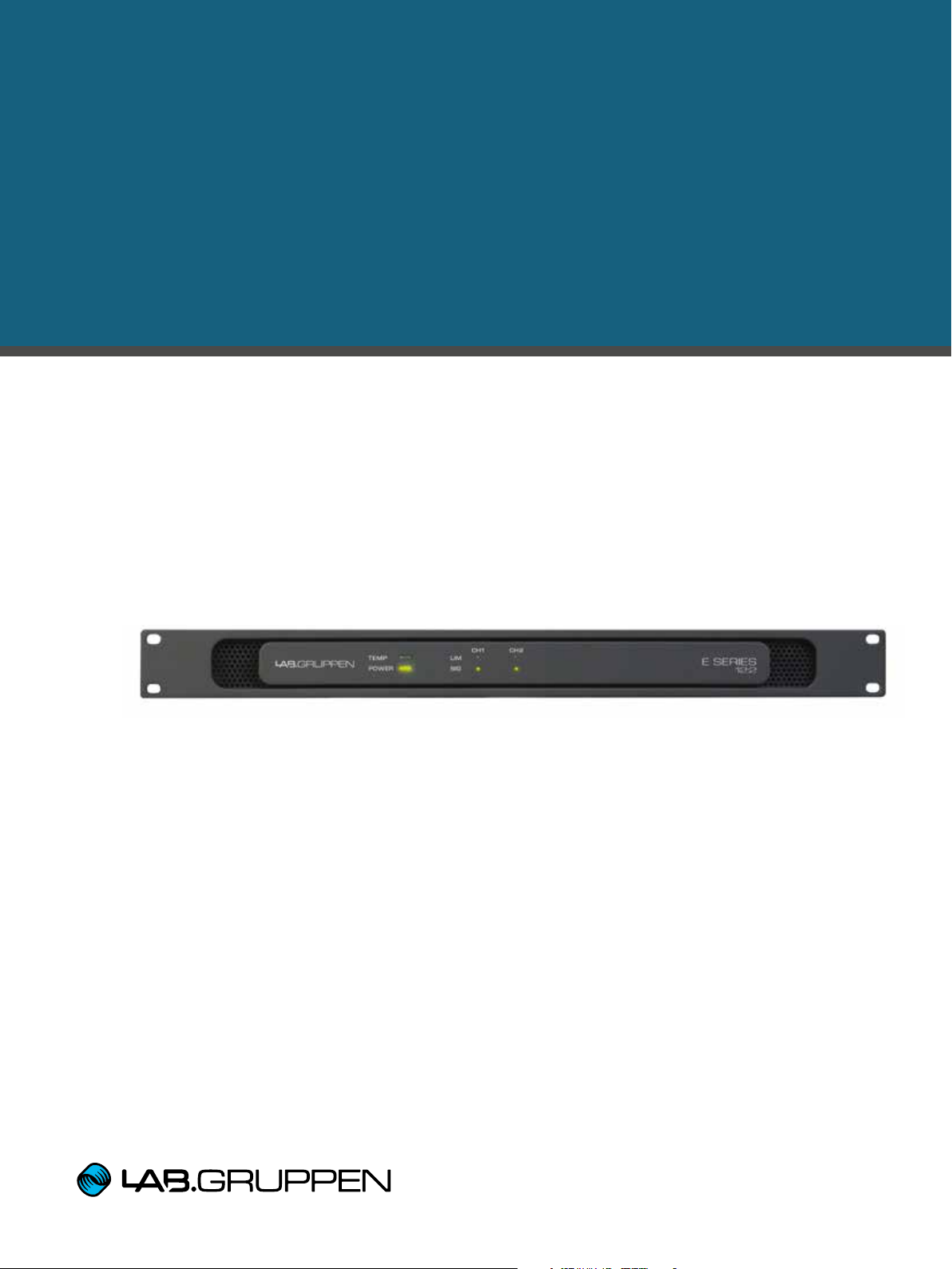
E SERIES
ENERGY STAR® qualified installation amplifiers
▸ E 4:2
▸ E 8:2
▸ E 12:2
Operation Manual
Page 2
1. Important safety instructions
1. Important safety instructions
Before using your E Series, be sure to carefully read the applicable items of this Operation Manual and the Safety
Instructions.
1. Read these instructions.
2. Keep these instructions
3. Heed all warnings.
4. Follow all instructions.
5. Do not use this apparatus near water.
6. Clean only with a dry cloth.
7. Do not block any ventilation openings. Install in accordance
with the manufacturer’s instructions.
8. Do not install near any heat sources such as radiators, heat
registers, stoves, or other apparatus (including ampliers) that
produce heat.
9. D o no t defe a t th e safe t y purp o s e of the po l a r i zed or grou n d i n g type plug. A polarized plug has two blades with one wider
than the other. A grounding-type plug has two blades and
a third grounding prong. The wide blade or the third prong
is provided for your safety. If the provided plug does not t
into your outlet, consult an electrician for replacement of the
obsolete outlet.
10. Protect the power cord from being walked on or pinched,
particularly at plugs, convenience receptacles, and the point
where they exit from the apparatus.
11. Only use attachments/accessories specied by the
manufacturer.
12. Use only with a cart, stand, tripod, bracket, or table specied
by the manufacturer, or sold with the apparatus. When a
cart is used, use caution when moving the cart/apparatus
combination to avoid injury from tip-over.
13. Unplug this apparatus during lightning storms or when
unused for long periods of time.
14. Refer all servicing to qualied service personnel. Servicing
is required when the apparatus has been damaged in any
way, such as power-supply cord or plug is damaged, liquid
has been spilled or objects have fallen into the apparatus, the
apparatus has been exposed to rain or moisture, does not
operate normally, or has been dropped.
2. Approvals
This equipment conforms to the requirements
of the EMC Directive 2004/108/EC and the
requirements of the Low Voltage Directive
2006/95/EC.
Standards applie d: EMC Emission EN551031, E3
EMC Immunity EN55103-2, E3, with S/N below
1% at normal operation level.
Electrical Safety EN60065, Class I
This equipment is tested and listed according to the
U.S. safety standard ANSI/ UL 60065 and Canadian safet y standard CSA C22.2 NO. 60065. UL
made the tests and they
are a Nationally Recognized Testing
Laboratory (NRTL).
This equipment is tested and found to comply with
the limits of a Class A device in part 15B of the FCC
rules. UL made these tests.
This equipment has been certied to comply
with PSE for Japan.
This equipment has been certied by CQC to
conform to CCC.
E Series is ENERGY STAR 3.0
qualied; this has been certied by UL.
3. Warnings
E SERIES Operation Manual rev 2.0.0
2
3.1 Explanation of warning symbols
The lightning bolt triangle is used to
alert the user to the presence of
un-insulated “dangerous voltages”
within the unit’s chassis that may be
of sufcient magnitude to constitute a
risk of electric shock to humans.
The exclamation point triangle is used to
alert the user to presence of important
operating and service instructions in the
literature accompanying the product.
Page 3
110-125 V (US)
UL817 and CSA C22.2 no 42.
220 -230 V (EUROPE)
CEE 7 page VII, S R section 107-2-D1/
IEC 83 page C4.
240 V (U K)
BS 1363 of 1984. Specication for
13 A fused plugs and switched and
unswitched socket outlets.
3. Warnings
3.2 Warnings
To reduce risk of re or electric shock, do not expose this
apparatus to rain or moisture.
Français: Pour réduire les risques d’incendie ou de choc
électrique, n’exposez pas l’appareil à la pluie ou à l’humidité.
Do not expose this system/apparatus to dripping or splashing
and ensure that no objects lled with liquids, such as vases,
are placed on the apparatus.
Français: N’exposez pas ce système/appareil au
ruissellement ni aux éclaboussures et assurez-vous qu’aucun
objet contenant du liquide tel qu’un vase n’est placé sur
l’appareil.
This apparatus must be connected to a mains socket outlet
with a protective earthing connection.
Français: Cet appareil doit être raccordé à une prise secteur
avec terre de protection.
The mains plug is used as a disconnect device and shall
remain readily operable.
Français: La che d’alimentation sert de dispositif de
déconnexion et doit rester constamment accessible.
To prevent electric shock do not remove top or bottom covers.
No user serviceable parts inside. Refer servicing to qualied
service personnel.
Français: Pour prévenir un choc électrique, ne retirez pas
les capots du dessus et du dessous. Aucune pièce n’est
réparable par l’utilisateur à l’intérieur. Conez toute réparation
à un personnel de maintenance qualié.
To completely disconnect this equipment from the AC mains,
disconnect the power supply cord plug from the ac receptacle.
The mains plug of the power supply cord shall remain readily
operable.
Français: Pour totalement isoler l’équipement de l’alimentation
secteur, débranchez le cordon d’alimentation de son
embase. La che secteur du cordon d’alimentation doit rester
accessible.
Do not install this device in a conned space.
Français: N’installez pas cet appareil dans un espace conné.
Check the voltage in your area and use the correct type of mains
connector.
Français: Vériez la tension en vigueur dans votre région et
utilisez le bon type de che secteur.
Please refer to the following table:
Voltage Line plug (according to standard)
3.3 User responsibility
3.1.1 Mains connection grounding
Your amplier must be connected to a grounded socket outlet.
3.1.2 Speaker output hazard
Power ampliers are capable of producing hazardous output
voltages. To avoid electrical shock, do not touch any exposed
speaker wiring while the amplier is operating. External wiring
connected to the speaker terminals shall be installed by a
qualied person, or ready-made leads or cords of appropriate
capacity shall be used. As the amplier outputs produce high
voltage, do not connect or disconnect speaker cables when
the mains power is on.
3.1.3 Radio interference
A sample of this product has been tested and complies with
the limits for the European Electro Magnetic Compatibility
(EMC) directive. It also has been tested and found to comply
with the limits for a Class A digital device, pursuant to Part
15 of the FCC Rules. These limits are designed to provide
reasonable protection against harmful interference from
electrical equipment. This product uses radio frequency
energy and, if not used or installed in accordance with these
operating instructions, may cause interference to other
equipment, such as radio receivers. However, there is no
guarantee that interference will not occur in a particular
installation. If this equipment causes harmful interference
to radio or television reception (determined by turning the
equipment on and off), the user may be able to correct the
interference by one or more of the following measures:
• Check if the affected unit complies with the EMC limits for
immunity, (CE-labeled). If not, address the problem with
the manufacturer or supplier. All electrical products
sold in the EC must be approved for immunity against
electromagnetic elds, high voltage ashes, and radio
interference.
• Consult the dealer or an experienced radio/TV technician
for help.
• Reorient or relocate the antenna.
• Increase the separation between the equipment and
receiver.
• Connect the equipment into an outlet on a circuit different
from that to which the receiver is connected.
3.1.4 Speaker damage
Many loudspeakers can be easily damaged or destroyed by
overpowering them. Always check the speaker’s continuous
and peak power capabilities. Although the amplier’s
attenuators can be used to reduce the overall gain, an
increase of the input signal can still result in full output power,
which may cause damage to connected speakers.
3.1.5 Maintenance
For safe and reliable operation, any dust collected in the front
panel should be removed regularly. In rare circumstances,
accumulated dust could ignite due to high internal
temperatures and cause a re. If the front is clogged so that
air cannot pass, then the unit will eventually go into thermal
protection; any resultant problems will not be covered by the
wa rr an ty.
E SERIES Operation Manual rev 2.0.0
3
Page 4

4. Table of Contents
4. Table of Contents
1. Important safety instructions 2
2. Approvals 2
3. Warnings 2
3.1 Explanation of warning symbols 2
3.2 Warnings 3
3.3 User responsibility 3
5. Introduction 6
5.1. Welcome 6
5.2. Features 6
5.2.1. Class D output stage and universal power supply with low current draw 6
5.2.2. Amplier sensitivity / gain 7
5.2.3. Protection and performance optimization 7
5.2.4. 50 Hz high-pass lter 8
5.2.5. Auto Power Down / On (APD / APO) scheme 8
5.2.6. General Purpose Input / Output (GPIO) facilities 8
6. Unpacking and visual checks 8
7. Installation 9
7.1. Mounting 9
8. Cooling and fan operation 9
9. Operating voltage 10
10. Grounding 10
11. Front panel 11
12. Rear panel 12
12.1. Power 12
12.2. Input Signal Present Threshold (SPT) 13
E SERIES Operation Manual rev 2.0.0
4
Page 5

4. Table of Contents
13. Operation and performance 14
13.1. Introduction 14
13.2. Operating precautions 14
13.3. Signal ow and headroom 14
13.4. Audio input and output connections, setup and features 15
13.4.1. Balanced / unbalanced Input connection 15
13.4.2. Output operation and connection 15
13.4.3. Output bridge mode and asymmetric loading 16
13.4.4. Constant Voltage 70 V system setup and operation 18
13.4.5. Output Current Peak Limiter (CPL) 18
14. Appendices 18
14.1. Maintenance 18
14.2. Thermal dissipation 19
14.3. Asymmetric loading data 20
14.4. Technical specications 24
15. Warranty 25
16. Service 26
E SERIES Operation Manual rev 2.0.0
5
Page 6

5. Introduction
5. Introduction
5.1. Welcome
Thank you for choosing a Lab.gruppen E Series product built around Lab.gruppen’s IDEEATM, the IntelliDrive
Energy Efcient Amplier. This manual provides a comprehensive guide to the features and functionality of E Series
model E 12:2, E 8:2 and E 4:2 ampliers. Please read through this manual in its entirety to become fully acquainted
with conguration options and protection circuitry.
This brief summary, in conjunction with Installation (Section 7), contains the basic information needed to safely
install the amplier and place it in service. However, we highly recommend reading through this manual in its
entirety, beginning with Features and Technologies and continuing through to Operation and Performance. As you
become thoroughly familiar with all aspects of operation, you may learn of features or options that will affect your
choices on amplier modes or loudspeaker system conguration.
Lab.gruppen E Series power ampliers are designed and built specically for the unique demands of permanent
installation applications. By packing two channels of efcient recongurable power amplication into a 1U chassis,
the E Series achieves a high power and channel density. The benets include reduced rack space requirements
and minimal heat build-up. The exible output stages enable each amplier channel to be set for either low
impedance or “70 V”-constant voltage (70.7 Vrms = 100 V peak) mode.
Although E Series features and facilities are tailored for installation applications, each amplier draws on the
foundational engineering that has made Lab.gruppen the benchmark of quality for touring concert systems:
exceptional sonic performance, rugged construction, proven reliability, and protection features that anticipate every
unwelcome possibility.
This manual was created for the E Series E 12:2, E 8:2 and E 4:2 amplier models. Any references to “E Series” in
this manual refer to all models in the range.
5.2. Features
Your new E Series amplier incorporates a number of sophisticated technologies – many of them proprietary to
Lab.gruppen – that ensure the best possible performance and years of reliable operation. Familiarizing yourself with
these technologies will prove invaluable in setting up and optimizing your loudspeaker system.
5.2.1. Class D output stage and universal power supply with low current draw
All E Series ampliers employ a unique Class D output stage that is ideally matched to the rated power output. To
provide exibility, each channel offers sufcient voltage swing and current capacity to drive either constant voltage
(“70 V”) or low impedance (2/4/8 or 16 ohms). In order to have low thermal losses as well as the voltage swing
required to drive 70 V, the design is based on a permanently bridged output.
E SERIES Operation Manual rev 2.0.0
6
Page 7

5. Introduction
5.2.2. Amplifier sensitivity / gain
For ease of use in system integration, E Series have been designed with a xed sensitivity of 4 dBu. Each model
offers two operational modes individually selectable per channel:
* “70 V” – Optimized for constant voltage systems but also can be used when load impedance is 8 ohms or higher.
Input signal of 4 dBu produces 70.7 Vrms output, for gain of 35.2 dB.
* “Lo-Z” – Optimized for driving loads with impedance below 16 ohms. Input signal of 4 dBu produces the rated
burst power into 4 ohms; gain varies by model.
5.2.3. Protection and performance optimization
Appropriate and reliable power amplication is vital to any audio system. Inadequate or faulty power ampliers
could cause damage to loudspeakers, or in some cases to the power ampliers themselves. To prevent damage
or service interruptions, E Series ampliers offer advanced features to protect both internal circuits and connected
loads. These features include the mains current limiter that allows several ampliers to be connected to a typical
mains outlet.
Standard E Series protection features include:
• A CPL (Current Peak Limiter) ensures that the amplier’s output does not exceed the safe current handling
parameters of the amplier components.
• Temperature protection ensures that the amplier will not be damaged by exceeding thermal limits. A TEMP
indicator LED ashes when the amplier approaches thermal limits to allow user action before protective muting
engages.
• A PAL (Power Average Limiter) limits the maximum average power consumption from the mains.
• DC protection ensures destructive DC signals will not appear at the amplier outputs. If such conditions occur
an internal fuse opens.
Note! There is no open fuse indication on the amplier. If a channel indicates signal presence but
there is no sound, an open fuse could be the cause. If an internal fuse is blown, then the amplier
needs service.
• Under Voltage Limit - A temporarily low mains voltage will indirectly initiate limiting if a high output level
is attempted. In most circumstances, depending on signal characteristics and level, the amplier will remain
operational. This limiting allows the amplier to remain functional during sustained periods of lower mains
voltage, as well as during temporary dips and when very long mains cords are used.
• Low inrush current ensures that the mains breaker will not trip when several power ampliers are turned on
simultaneously.
E SERIES Operation Manual rev 2.0.0
7
Page 8

6. Unpacking and visual checks
5.2.4. 50 Hz high-pass filter
Each channel has a switchable 50 Hz high-pass lter. In the default full-range position the amplier has a at
response with a -3 dB point at 2 Hz. When engaged, the lter rolls off low frequencies (12 dB/octave) for greater
efciency and reliability in, for example, 70 V high-impedance systems where the removal of very low frequency
content may be desired. The lter can also be used if desired when the output channel is connected to low
impedance loudspeakers that are unable to reproduce deep bass frequencies.
5.2.5. Auto Power Down / On (APD / APO) scheme
To comply with Energy Star 3.0 requirements, all E Series ampliers incorporate an APD scheme with power
consumption below 1 W in sleep/standby mode. The E Series will go to standby mode after 20 minutes without
input signal.
E Series also incorporates an APO functionality that restores full operation less than two seconds after signal is
applied to either of the inputs. Section 12.2 describes the threshold that is used.
5.2.6. General Purpose Input / Output (GPIO) facilities
The GPIO connections allow seamless interfacing with many third-party control and power sequencing systems.
Functions are optional; the ampliers will operate normally when GPIO is not connected.
The General Purpose Input (GPI) controls the power state via external contact closure as follows:
• It reacts to a transition from open to closed by forcing the unit to the on state. The APD function will still apply,
and the on state will be retained after a power cycle.
• It reacts to a transition from closed to open by forcing the unit to the standby state. This will also disable the
APO until it is turned on again.
The General Purpose Output (GPO) is an internal contact closure that, when closed, indicates the unit is on and
both channels functional (neither muted due to high temperature). Open indicates that the amplier is either in
standby or protective mute is activated in one or both channels.
6. Unpacking and visual checks
Every Lab.gruppen amplier is carefully tested and inspected before leaving the factory and should arrive in perfect
condition. If any damage is discovered, please notify the shipping carrier immediately. Save the packing materials
for the carrier’s inspection and for any future shipping.
E SERIES Operation Manual rev 2.0.0
8
Page 9

7. Installation
7. Installation
7.1. Mounting
The amplier is one rack unit high (1U) and will t into a standard EIA 19” rack. The depth is 276 mm (10.9”). The
weight is approximately 4.2 kg (9.3 lbs) depending on model type.
Free airow from front-to-rear of the amplier must be allowed. Therefore, no doors or rack-lids should be mounted
in front of or behind the ampliers.
Ampliers may be stacked directly on top of each other. There is no need for spacing in between units, although
spacing might enable more convenient installation of cabling on the rear panel.
8. Cooling and fan operation
The E Series ampliers have very low idle power draw and they are very efcient. However, to reduce the risk
of engaging thermal protection, the amplier has been designed with a forced-air cooling system (air ow from
front-to-rear) that activates as needed. Front-to-rear airow is preferred as cooler air is present at the front in nearly
all installed applications, allowing higher continuous power levels without encountering thermal problems.) Never
attempt to reverse the airow.
Always allow adequate air supply in front of the amplier, and ensure that the rear of the amplier has sufcient
space to allow exhaust to escape. If the amplier is rack-mounted, do not use covers or doors on the front or rear
of the rack.
Should a heat sink overheat, the temperature sensing circuits will mute the overheating channel. If the power
supply overheats, another sensing circuit will mute all output channels until the power supply cools to safe
operating temperature. An early warning before shut down will be indicated on the front-panel TEMP LED.
Always make sure that the recessed dust grille in the front is clean to ensure maximum possible airow as this will
minimize the risk of thermal protection, any required repairs are not covered by the warranty.
To calculate the maximum heat emission value when installing the ampliers in rooms with an air-conditioning
system, please refer to the Thermal Dissipation specications provided in the Appendix (Section 14.2).
E SERIES Operation Manual rev 2.0.0
9
Page 10

9. Operating voltage
9. Operating voltage
All E Series ampliers have a universal power supply that accepts mains voltages from 100-240 V @ 50 or 60 Hz.
The amplier requires 85 V to start, but will remain in service with mains voltage dips down to 60 V; however,
power output will be limited if it’s less than 100 V. An IEC male receptacle is provided on the rear panel of all
ampliers. The IEC cord included with each amplier has a male plug appropriate for the power receptacles in the
country in which it was sold. If substituting a different IEC mains cord for use in another country, use only a cord
that is grounded and approved for 3 A or more. Make sure it is connected to a grounded mains outlet.
Once a suitable AC supply is connected, the amplier will go into standby as indicated by amber illumination of the
“power” LED (front and rear panel).
When the amplier is turned on it goes through a soft-start sequence as it self-checks its circuits. The “power” LED
becomes green to indicate that the amplier is on.
10. Grounding
E Series ampliers have no ground lift switch or terminal. The signal ground is always oating, via a resistor, to
chassis and therefore the grounding system is automatic.
In the interests of safety, never disconnect the earth (ground) pin on the AC power cord. Use balanced input
connections to avoid hum and interference. If this is not possible; connect the “–” pin to signal ground.
E SERIES Operation Manual rev 2.0.0
10
Page 11

11. Front panel
11. Front panel
The front panel presents the following amplier status indicators:
1 Power – Indicates standby mode with amber and on mode with green.
2 Temperature – Flashes amber to for early warning if the temperature is high in either the PSU or one of the
output channels. Dangerously high temperature initiates muting, as indicated with constant amber light.
3 Input Signal Present – Illuminates when the input signal level exceeds the Signal Present Threshold (SPT).
4 Lim – Illuminates when the amplier is limiting the signal.
E SERIES Operation Manual rev 2.0.0
11
Page 12

12. Rear panel
00-240V 50-60Hz
Locking IEC; must be grounded/earthed
Ser. N:o
Removed!
E 12:2
Audio Power Amplifier
for professional use
Designed in Sweden
manufactured in Thailand
4GC7
12. Rear panel
CONTROL MONITOR
GPO
GPI
GPIO
connectors
CH
1
CHANNEL 1
CH
2
HIGH
70V
PASS
SIG
Lo-Z
FULL
RANGE
3-pole block
type input
connectors
CHANNEL 2
-10dB
-10dB -10dB
HIGH
70V
PASS
-Inf 0
Lo-Z
FULL
RANGE
-10dB
SIG
-Inf 0
Switches,
indicator and
attenuator per
channel
POWER
Power control
and indicator
BALANCED SPEAKER OUTPUTSBALANCED INPUTSPOWER STATE
CH
1
DO NOT
CONNECT ANY
TERMINAL TO
GROUND.
CLASS 2 WIRING
2-pole block
type output
connections
CH
2
Locking IEC; must be grounded/earthed
Ser. N:o
00-240V 50-60Hz
Removed!
E 12:2
Designed in Sweden
manufactured in Thailand
Audio Power Amplifier
for professional use
4GC7
Mains input
100 -240
VAC,
@ 50 or 60 Hz
12.1. Power
The Power control button is located in the middle. When pressed momentarily it toggles the power state
between standby and on.
The Power state indicator is located to the right of the button. It illuminates amber as soon as the amplier reaches
standby, and turns green when the amplier is fully on.
POWER
BALANCED SPEAKER OUTPUTS
CH
1
CH
2
E SERIES Operation Manual rev 2.0.0
12
DO NOT
CONNECT ANY
TERMINAL TO
GROUND.
CLASS 2 WIRING
Page 13

12. Rear panel
The following features are located on the rear panel of the E Series:
1 Attenuators – Individual attenuation for the two amplier channels. Range is 0 dB to -innity. The 12 o’clock
position indicates -10 dB attenuation. The sensitivity for the amplier is 4 dBu when the attenuator is at 0 dB and
14 dBu when the attenuator is at -10 dB.
2 SIG – The green indicator will be lit whenever the input signal is above the signal present threshold. Indication
is the same as the front panel indicator is currently playing.
3 High-pass / Full-range – Selects either at down to 2 Hz or High Pass lter at 50 Hz.
70 V / Lo-Z – This switch denes the settings for the Rail Sensing LimiterTM (RSL).
• 70 V should be used for constant voltage systems and if full rated power into 8 or 16 ohms loads is required.
• Lo-Z should be used for rated power into 2 or 4 ohms loads. It can also be used to limit the maximum power
into 8 or 16 ohms loads.
If more than half the total power is required for one channel driving an impedance of 4 ohms or higher, then the
70 V setting can be used for this channel.
Operation into 2 ohms is not recommended when using 70 V mode.
4 Output – The detachable output block connectors are designed and approved for 41 Arms (much more than
the maximum capacity of the ampliers). Cables up to 8 mm2 (8 AWG) may be used. Please ensure that all leads
are securely attached inside the connector to avoid short circuits. Also verify that the loudspeakers are connected
with the same polarity to avoid low frequency cancellation losses.
5 GPIO – The amplier comes with an Automatic Power On / Down APO / APD scheme triggered by the program
material, so in many applications external power control is not necessary. If remote power control is desired, then
an external relay can be connected to the GPI control port.
12.2. Input Signal Present Threshold (SPT)
As shipped the default input signal threshold is set at -56 dBu (-60 dB relative to 4 dBu, which is the sensitivity).
This threshold applies to the input signal present indicators on the front and rear panels as well as to the
Auto Power On / Down (APO / APD).
If this threshold is deemed too high or low, it can be trimmed by pressing and holding the power button for two
full seconds. The amplier will then sample the input signal and set the SPT threshold 6 dB above the sampled
noise oor. The procedure should be done with all “front end” equipment on, but with no active signal input. Please
ensure that no audio is accidently passed during this calibration as that can lead to a high SPT that in turn could
generate and store an undesirable threshold for APD.
A typical scenario for changing the default would be when the source has a very high noise oor. In this case,
adjusting the threshold prevents the noise from triggering a false APO. The calibration procedure detects the higher
noise oor and sets the SPT threshold at 6 dB above it.
E SERIES Operation Manual rev 2.0.0
13
Page 14

13. Operation and performance
13. Operation and performance
13.1. Introduction
The following sections provide comprehensive information on amplier connection, setup, operation, and
performance. The detailed information included here is essential to realizing the full functionality of the
E Series ampliers.
13.2. Operating precautions
• Make sure that the amplier is off or in standby mode before making any input or output connections.
• This amplier is equipped with a Universal Power Supply that handles nominal voltages from 100 V to
240 V @ 50 - 60 Hz. It will turn on between 85 V – 264 V. For full power it requires 100 V or more, but it
will remain functional at voltages above 60 V with reduced output power.
13.3. Signal flow and headroom
All E Series ampliers have the same signal ow and feature set, differing only in the ability to deliver power to the
loudspeakers.
Clip, Thermal &
Rail sense
Balanced input
terminal
(17.2 dBu
headroom)
High pass filter
(2 Hz / 50 Hz)
Attenuator
Rail Sense Limiter
(4 dBu for full
output Voltage)
This block also
implements the
protection
Bridged amplifier
(Gain depends
on RSL)
Loudspeaker
output terminal
On all E Series ampliers, the input stage has a relatively high sensitivity of 4 dBu (1.23 Vrms) for full power.
However, the input can handle signals up to 17.2 dBu without clipping the input signal path. The amplier applies
low-distortion limiting if the input signal exceeds what is required to deliver full power. If compression isn’t desired,
use the input attenuator to trim the sensitivity. E Series ampliers easily achieve a high SPL when driven with
sources capable of 10 or 20 dBu output, such as professional mixing consoles or DSP units.
However, consumer sources such as a CD player or an MP3 player will have a lower output, typically -10 dBV or
-7.8 dBu. This is not sufcient level to realize full power from an E Series amplier. In this scenario, the user can
get closer to maximum power output by putting the mode switch in the 70 V position without risk of delivering
excessive power, even into a 2 or 4 ohm load.
E SERIES Operation Manual rev 2.0.0
14
Page 15

13. Operation and performance
POWER
CHANNEL 1
CHANNEL 2
-10dB -10dB
SIG
HIGH
PASS
70V
SIG
HIGH
PASS
70V
-Inf 0
-10dB
-Inf 0
-10dB
13.4. Audio input and output connections, setup and features
13.4.1. Balanced / unbalanced Input connection
BALANCED INPUTS
CH
1
Electronically balanced, Phoenix-type inputs are provided on all channels. Follow the +,– and Ground labels when
connecting the input signal.
If an unbalanced connection is desired this can be achieved by summing the minus (“COLD”) and Ground
terminals and using the + terminal as the “HOT” signal. For the best possible performance, the summing of ground
and minus wires should be done at the source unit end of the cable (e.g. a CD player).
CH
2
Connectors are supplied for attaching cables to the inputs. Compatible input connectors are Phoenix Contacts,
Part number MSTB 2.5/3-STZ-5.08 , or Anytek OQ03545100CCG.
When linking the same source signal to several input channels, be aware that there is a limit to the number of
channels an output source can “drive”. A typical output source (e.g. a DSP crossover unit) can drive up to four
amplier channels before line-drivers would be required to boost the signal.
13.4.2. Output operation and connection
Detachable block-connectors with + and – poles are provided at each channel output for connection of the
speakers. If more conectors are needed, then these are compatible:
Phoenix 1709047, or Anytek KT02015000CCG.
Make sure that the speaker cables are connected correctly and tightly, and that accurate polarity is maintained to
all speakers in the system.
As the amplier outputs produce high voltage, do not connect or disconnect speaker cables when the mains
power is on.
E SERIES Operation Manual rev 2.0.0
15
Page 16

13. Operation and performance
Channel 1 Channel 2
Model RSL switch Load t ype
Power
available
RSL switch Load t ype
Power
available
E 4:2 70 V 70 V 50 W 70 V 70 V 350 W
E 4:2 70 V 70 V 200 W 70 V 70 V 200 W
E 8:2 70 V 70 V 100 W 70 V 70 V 700 W
E 8:2 70 V 70 V 0 W 70 V 70 V 800 W
E 12:2 70 V 70 V 200 W 70 V 70 V 1000 W
13.4.3. Output bridge mode and asymmetric loading
The E Series is designed with inherently bridged outputs for a high voltage swing, with full headroom accessed in
the 70 V mode. So, in some ways the amplier is a 4 channel amplier with permanently bridged outputs which
turns it into a 2 channel amplier. This design also accommodates asymmetric loading, wherein only one channel
can be connected and draw all power from the power supply. Alternatively, one channel can be connected and
congured as a “high power” channel while another is connected and congured as a “low power” channel. For
example, a 4 ohm loudspeaker could draw all the power available from the power supply in one channel when it is
the only loudspeaker connected to the amplier. If another channel is connected, any power used by this second
“low power” channel will limit the “high power” channel from using all available power.
The power available in each channel is determined by the setting of the RSL switch and the impedance of the
connected load. Power available per channel in some typical applications is shown in the following sample tables.
Note that because the two channels are identical, the channels given below are reversible. (If settings of channel 2
are same as for channel 1 shown below, then options for channel 1 are same as for channel 2 below.)
From one perspective, the functionality of asymmetric loading is very intuitive: essentially, power not used in one
channel is available through the other channel, but within limits determined by the load impedances for each
channel and the setting of the RSL switch. However, the possible combinations are many, and performance
limitations may apply in some scenarios.
The tables below illustrate power levels available in different scenarios with different ampliers. These are not
complete, but given only to illustrate the concept; more complete data for all three ampliers is given in
Section 14.3.
System example A: 70 V systems on both channels
E SERIES Operation Manual rev 2.0.0
16
Page 17

13. Operation and performance
Channel 1 Channel 2
Model RSL switch Load t ype
Power
available
RSL switch Load t ype
Power
available
E 4:2 70 V 70 V 50 W 70 V 8 ohms 350 W*
E 4:2 70 V 70 V 300 W Lo-Z 8 ohms 100 W
E 8:2 70 V 70 V 200 W 70 V 8 ohms 600 W
E 12:2 70 V 70 V 900 W Lo-Z 8 ohms 300 W
E 12:2 70 V 70 V 600 W 70 V 8 ohms 600 W
Channel 1 Channel 2
Model RSL switch Load t ype
Power
available
RSL switch Load t ype
Power
available
E 4:2 70 V 70 V 100 W 70 V 4 ohms 300 W*
E 8:2 70 V 70 V 300 W 70 V 4 ohms 500 W*
E 8:2 70 V 70 V 400 W Lo-Z 4 ohms 400 W
E 12:2 70 V 70 V 400 W 70 V 4 ohms 800 W*
E 12:2 70 V 70 V 600 W Lo-Z 4 ohms 600 W
Channel 1 Channel 2
Model RSL switch Load t ype
Power
available
RSL switch Load t ype
Power
available
E 4:2 Lo-Z 4 ohms 200 W 70 V 8 ohms 200 W*
E 8:2 Lo-Z 4 ohms 400 W 70 V 8 ohms 400 W
E 8:2 Lo-Z 4 ohms 200 W* 70 V 8 ohms 600 W
E 12:2 Lo-Z 4 ohms 600 W 70 V 8 ohms 600 W
E 12:2 70 V 4 ohms 900 W* Lo-Z 8 ohms 300 W
System example B: 70 V system channel 1 plus one 8 ohm subwoofer (or other cabinet) channel 2
System example C: 70 V system channel 1 plus two 8 ohm subwoofers (or cabinets) in parallel for
4 ohms channel 2
System example D: Two 8 ohm cabinets in parallel for 4 ohms channel 1 and one 8 ohm subwoofer
(or cabinet) channel 2
*: Use of external limiter recommended with these examples. Otherwise, depending on the program material,
the amplier may temporarily try to deliver more power with resulting pumping.
E SERIES Operation Manual rev 2.0.0
17
Page 18

14. Appendices
13.4.4. Constant Voltage 70 V system setup and operation
When using E Series ampliers to drive constant voltage (high-impedance) speaker systems at 70 Vrms or 100 V
peak, in most cases you can simply connect the speakers to the amplier output terminals, select the 70 V RSL
setting, and place the amplier in service.
Limiters - Limiting is applied to avoid distortion at the selected voltage limit threshold and to avoid hitting the rail if it
has sagged below the selected threshold.
Limiting also may be applied when maximum output current has been reached or when the mains voltage is too
low to maintain required rail voltage. Limiting activity is shown by the front panel Limiter LED.
13.4.5. Output Current Peak Limiter (CPL)
The Current Peak Limiter (CPL) ensures that the amplier will not be damaged by trying to deliver current to the
outputs exceeding the physical limitations of the output devices. The CPL keeps the amplier within the Safe
Operating Area. The CPL is non-adjustable and has different limit values depending on model type. The maximum
output current values for the three E Series models are:
• E 12:2, 18 Arms per channel
• E 8:2, 16 Arms per channel
• E 4:2, 14 Arms per channel
14. Appendices
14.1. Maintenance
During normal operation your E Series amplier will provide trouble-free service. The only user maintenance
required is to periodically vacuum clean the air inlets in the front.
In some extreme cases it may be necessary for authorized service personnel to clean the inside of the amplier in
order to safely remove dust or other build ups which may occur during prolonged normal usage. If you are using
your amplier in a heavy duty application, it is recommended to have your amplier cleaned inside every 3 years
purely as a preventative action.
E SERIES Operation Manual rev 2.0.0
18
Page 19

14.2. Thermal dissipation
E 8:2
Level Load Outp ut power
Line
curr ent *2)
Watt *1) Thermal Dissipation
120 VA C 230 VAC In Out
Dissi
-
pated
BTU/hr kCal/hr
Standby w. remote Power Off.
0.033 0.72 0 0.7 2.5 0.6
0.016 0.38 0 0.4 1.3 0.3
Power on, Idling
0.1 83 20.7 0 2 0.7 70.5 1 7.8
0.315 21.9 0 21. 9 74 .7 18.8
Pink Ps eudo
Noise (1/8)
70 V / Ch. 400 x 2
1.2 13 9 10 0 39 13 4 34
2.1 14 8 100 48 163 41
16 ohms / Ch. 310 x 2
0.9 112 78 35 11 9 30
1.8 118 78 35 119 30
8 ohms / Ch. 400 x 2
1.2 141 100 41 14 0 35
2.0 148 10 0 48 16 4 41
4 ohms / Ch. 400 x 2
1.3 149 10 0 49 16 6 42
2.1 15 5 10 0 55 187 47
2 ohms / Ch. 400 x 2
1.4 172 10 0 72 244 61
2.3 174 100 74 254 64
*1) The ampli er’s PSU oper ates as a non- resistive load , so the calcula tion “Volts x Amp s = Watts” would not b e correct. Ins tead, measured a nd specied h ere
is what is kn own as the “Active Power ” in the amplier p roviding usefu l, real-wor ld values of power c onsumption and h eat dissipati on.
*2) Curre nt draw gures mea sured at 230 V. as well a s 120 V. The efcienc y is similar, but not ide ntical for the t wo scenarios. T he efcien cy for 100 V mains is
very sim ilar to that of 120 V.
E 4:2
Level Load Outp ut power
Line
curr ent *2)
Watt *1) Thermal Dissipation
120 VA C 230 VAC In Out
Dissi
-
pated
BTU/hr kCal/hr
Standby w. remote Power Off.
0.32 0.7 0 0.72 2.5 0.6
0.016 0.4 0 0.38 1.3 0.3
Power on, Idling
0.1 86 21. 5 0 21.5 73.3 18.5
0.306 22.4 0 22.4 76.6 19.3
Pink Ps eudo
Noise (1/8)
70 V / Ch. 200 x 2
0.7 80 50 30 101 26
1.1 86 50 36 123 31
16 ohms / Ch. 200 x 2
0.7 80 50 30 101 26
1.1 85 50 35 11 8 30
8 ohms / Ch. 200 x 2
0.7 81 50 31 105 26
1.1 87 50 37 125 32
4 ohms / Ch. 200 x 2
0.8 89 50 39 13 3 34
1.2 92 50 42 144 36
2 ohms / Ch. 200 x 2
0.8 98 50 48 16 5 42
1.3 10 0 50 50 172 43
*1) The ampli er’s PSU oper ates as a non- resistive load , so the calcula tion “Volts x Amp s = Watts” would not b e correct. Ins tead, measured a nd specied h ere
is what is kn own as the “Active Power ” in the amplier p roviding usefu l, real-wor ld values of power c onsumption and h eat dissipati on.
*2) Curre nt draw gures mea sured at 230 V. as well a s 120 V. The efcienc y is similar, but not ide ntical for the t wo scenarios. T he efcien cy for 100 V mains is
very sim ilar to that of 120 V.
14. Appendices
E SERIES Operation Manual rev 2.0.0
19
Page 20

14. Appendices
E 12:2
Level Load Outp ut power
Line
curr ent *2)
Watt *1) Thermal Dissipation
120 VA C 230 VAC In Out
Dissi
-
pated
BTU/hr kCal/hr
Standby w. remote Power Off.
0.032 0.70 0 0.7 2.4 0.6
0.019 0.31 0 0.3 1.1 0.3
Power on, Idling
0.1 83 20.7 0 2 0.7 70.5 1 7.8
0.315 21.9 0 21. 9 74 .7 18.8
Pink Ps eudo
Noise (1/8)
70 V / Ch. 600 x 2
1.8 210 150 60 205 52
2.9 223 150 73 248 62
16 ohms / Ch. 33 x 2
1.1 128 83 45 154 39
1.8 13 6 83 54 183 46
8 ohms / Ch. 600 x 2
1.8 209 150 59 202 51
2.9 219 150 59 237 60
4 ohms / Ch. 600 x 2
1.9 222 150 72 245 62
2.9 226 150 76 259 65
2 ohms / Ch. 600 x 2
2.0 249 150 99 337 85
3.1 252 150 102 349 88
*1) The ampli er’s PSU oper ates as a non- resistive load , so the calcula tion “Volts x Amp s = Watts” would not b e correct. Ins tead, measured a nd specied h ere
is what is kn own as the “Active Power ” in the amplier p roviding usefu l, real-wor ld values of power c onsumption and h eat dissipati on.
*2) Curre nt draw gures mea sured at 230 V. as well a s 120 V. The efcienc y is similar, but not ide ntical for the t wo scenarios. T he efcien cy for 100 V mains is
very sim ilar to that of 120 V.
14.3. Asymmetric loading data
Pages 21-23 following list possible settings and load combinations for asymmetric loading. For an explanation of
asymmetric loading, please see Section 13.4.3.
For values followed by an asterisk (*), use of an external limiter may be required for optimum performance.
All values assume amplier is being driven by a signal from a professional mixing console or DSP unit. Values
will differ if driven by a consumer device, such as an iPod, with signicantly lower output (2.71 dBu instead of the
required 4 dBu).
E SERIES Operation Manual rev 2.0.0
20
Page 21

E 4:2
Channel RSL switch Channel load Power output
Ch. 1 Ch. 2 Ch. 1 Ch. 2 Ch.1 Ch. 2
70 V 70 V 70 V 70 V 0 W @ 70 V 400 W @ 70 V
70 V 70 V 70 V 70 V 50 W @ 70 V 350 W @ 70 V
70 V 70 V 70 V 70 V 100 W @ 70 V 300 W @ 70 V
70 V 70 V 70 V 70 V 150 W @ 70 V 250 W @ 70 V
70 V 70 V 70 V 70 V 200 W @ 70 V 200 W @ 70 V
70 V Lo-Z 70 V 2 ohms 100 W @ 70 V 300 W @ 2 ohms*
70 V Lo-Z 70 V 2 ohms 50 W @ 70 V 350 W @ 2 ohms*
70 V Lo-Z 70 V 4 ohms 350 W @ 70 V 50 W @ 4 ohms*
70 V Lo-Z 70 V 4 ohms 300 W @ 70 V 100 W @ 4 ohms*
70 V Lo-Z 70 V 4 ohms 250 W @ 70 V 150 W @ 4 ohms*
70 V Lo-Z 70 V 4 ohms 200 W @ 70 V 200 W @ 4 ohms
70 V 70 V 70 V 4 ohms 150 W @ 70 V 250 W @ 4 ohms*
70 V 70 V 70 V 4 ohms 100 W @ 70 V 300 W @ 4 ohms*
70 V 70 V 70 V 4 ohms 50 W @ 70 V 350 W @ 4 ohms*
70 V Lo-Z 70 V 8 ohms 350 W @ 70 V 50 W @ 8 ohms*
70 V Lo-Z 70 V 8 ohms 300 W @ 70 V 100 W @ 8 ohms
70 V 70 V 70 V 8 ohms 250 W @ 70 V 150 W @ 8 ohms*
70 V 70 V 70 V 8 ohms 200 W @ 70 V 200 W @ 8 ohms*
70 V 70 V 70 V 8 ohms 150 W @ 70 V 250 W @ 8 ohms*
70 V 70 V 70 V 8 ohms 50 W @ 70 V 350 W @ 8 ohms*
70 V Lo-Z 70 V 16 ohms 375 W @ 70 V 25 W @ 16 ohms*
70 V Lo-Z 70 V 16 ohms 350 W @ 70 V 50 W @ 16 ohms
70 V 70 V 70 V 16 ohms 300 W @ 70 V 100 W @ 16 ohms*
70 V 70 V 70 V 16 ohms 200 W @ 70 V 200 W @ 16 ohms*
70 V 70 V 70 V 16 ohms 90 W @ 70 V 310 W @ 16 ohms
70 V Lo-Z 4 ohms 16 ohms 375 W @ 4 ohms* 25 W @ 16 ohms*
70 V Lo-Z 4 ohms 16 ohms 350 W @ 4 ohms* 50 W @ 16 ohms
70 V 70 V 4 ohms 16 ohms 300 W @ 4 ohms* 100 W @ 16 ohms*
Lo-Z 70 V 4 ohms 16 ohms 200 W @ 4 ohms 200 W @ 16 ohms*
Lo-Z 70 V 4 ohms 16 ohms 90 W @ 4 ohms* 310 W @ 16 ohms
Lo-Z Lo-Z 4 ohms 16 ohms 200 W @ 4 ohms 50 W @ 16 ohms
70 V Lo-Z 4 ohms 8 ohms 350 W @ 4 ohms 50 W @ 8 ohms*
70 V Lo-Z 4 ohms 8 ohms 300 W @ 4 ohms* 100 W @ 8 ohms
70 V 70 V 4 ohms 8 ohms 250 W @ 4 ohms* 150 W @ 8 ohms*
70 V 70 V 4 ohms 8 ohms 225 W @ 4 ohms* 175 W @ 8 ohms*
Lo-Z 70 V 4 ohms 8 ohms 200 W @ 4 ohms 200 W @ 8 ohms*
Lo-Z Lo-Z 4 ohms 8 ohms 200 W @ 4 ohms 100 W @ 8 ohms
70 V Lo-Z 4 ohms 4 ohms 300 W @ 4 ohms 100 W @ 4 ohms*
70 V Lo-Z 4 ohms 4 ohms 250 W @ 4 ohms* 150 W @ 4 ohms*
Lo-Z Lo-Z 4 ohms 4 ohms 200 W @ 4 ohms 200 W @ 4 ohms
70 V 70 V 8 ohms 16 ohms 300 W @ 8 ohms* 100 W @ 16 ohms*
70 V Lo-Z 8 ohms 16 ohms 200 W @ 8 ohms* 200 W @ 16 ohms*
Lo-Z 70 V 8 ohms 16 ohms 100 W @ 8 ohms 300 W @ 16 ohms
70 V 70 V 8 ohms 8 ohms 200 W @ 8 ohms* 200 W @ 8 ohms*
70 V Lo-Z 8 ohms 8 ohms 300 W @ 8 ohms* 100 W @ 8 ohms
70 V Lo-Z 8 ohms 8 ohms 350 W @ 8 ohms* 50 W @ 8 ohms*
Lo-Z Lo-Z 2 ohms 16 ohms 350 W @ 2 ohms* 50 W @ 16 ohms
Lo-Z Lo-Z 2 ohms 8 ohms 300 W @ 2 ohms* 100 W @ 8 ohms
Lo-Z Lo-Z 2 ohms 4 ohms 200 W @ 2 ohms* 200 W @ 4 ohms*
Lo-Z Lo-Z 2 ohms 2 ohms 200 W @ 2 ohms* 200 W @ 2 ohms*
70 V unused 16 ohms unused 310 W @ 16 ohms unused
70 V unused 8 ohms unused 400 W @ 8 ohms* unused
70 V unused 4 ohms unused 400 W @ 4 ohms* unused
Lo-Z unused 2 ohms unused 400 W @ 2 ohms unused
70 V Lo-Z 16 ohms 16 ohms 310 W @ 16 ohms 50W @ 16 ohms
70 V 70 V 16 ohms 16 ohms 200 W @ 16 ohms* 200 W @ 16 ohms*
14. Appendices
E SERIES Operation Manual rev 2.0.0
21
Page 22

14. Appendices
E 8:2
Channel RSL switch Channel load Power output
Ch. 1 Ch. 2 Ch. 1 Ch. 2 Ch.1 Ch. 2
unused 70 V unused 70 V unused 800 W @ 70 V
70 V 70 V 70 V 70 V 50 W @ 70 V 750 W @ 70 V
70 V 70 V 70 V 70 V 100 W @ 70 V 700 W @ 70 V
70 V 70 V 70 V 70 V 150 W @ 70 V 650 W @ 70 V
70 V 70 V 70 V 70 V 200 W @ 70 V 600 W @ 70 V
70 V 70 V 70 V 70 V 300 W @ 70 V 500 W @ 70 V
70 V 70 V 70 V 70 V 400 W @ 70 V 400 W @ 70 V
70 V Lo-Z 70 V 2 ohms 200 W @ 70 V 600 W @ 2 ohms
70 V Lo-Z 70 V 2 ohms 300 W @ 70 V 500 W @ 2 ohms*
70 V Lo-Z 70 V 2 ohms 400 W @ 70 V 400 W @ 2 ohms*
70 V Lo-Z 70 V 2 ohms 500 W @ 70 V 300 W @ 2 ohms*
70 V Lo-Z 70 V 4 ohms 600 W @ 70 V 200 W @ 4 ohms*
70 V Lo-Z 70 V 4 ohms 500 W @ 70 V 300 W @ 4 ohms*
70 V Lo-Z 70 V 4 ohms 450 W @ 70 V 350 W @ 4 ohms*
70 V Lo-Z 70 V 4 ohms 400 W @ 70 V 400 W @ 4 ohms
70 V 70 V 70 V 4 ohms 300 W @ 70 V 500 W @ 4 ohms*
70 V 70 V 70 V 4 ohms 200 W @ 70 V 600 W @ 4 ohms*
70 V 70 V 70 V 4 ohms 150 W @ 70 V 650 W @ 4 ohms*
70 V 70 V 70 V 4 ohms 100 W @ 70 V 700 W @ 4 ohms*
70 V 70 V 70 V 4 ohms 50 W @ 70 V 750 W @ 4 ohms*
70 V Lo-Z 70 V 8 ohms 700 W @ 70 V 100 W @ 8 ohms*
70 V Lo-Z 70 V 8 ohms 600 W @ 70 V 200 W @ 8 ohms
70 V 70 V 70 V 8 ohms 500 W @ 70 V 300 W @ 8 ohms*
70 V 70 V 70 V 8 ohms 400 W @ 70 V 400 W @ 8 ohms*
70 V 70 V 70 V 8 ohms 300 W @ 70 V 500 W @ 8 ohms*
70 V 70 V 70 V 8 ohms 200 W @ 70 V 600 W @ 8 ohms
70 V Lo-Z 70 V 16 ohms 750 W @ 70 V 50 W @ 16 ohms*
70 V Lo-Z 70 V 16 ohms 700 W @ 70 V 100 W @ 16 ohms
70 V 70 V 70 V 16 ohms 650 W @ 70 V 150 W @ 16 ohms*
70 V 70 V 70 V 16 ohms 600 W @ 70 V 200 W @ 16 ohms*
70 V 70 V 70 V 16 ohms 490 W @ 70 V 310 W @ 16 ohms
70 V Lo-Z 4 ohms 16 ohms 750 W @ 4 ohms* 50 W @ 16 ohms*
70 V Lo-Z 4 ohms 16 ohms 700 W @ 4 ohms* 100 W @ 16 ohms
70 V 70 V 4 ohms 16 ohms 650 W @ 4 ohms* 150 W @ 16 ohms*
70 V 70 V 4 ohms 16 ohms 490 W @ 4 ohms* 310 W @ 16 ohms
Lo-Z 70 V 4 ohms 16 ohms 400 W @ 4 ohms 310 W @ 16 ohms
Lo-Z Lo-Z 4 ohms 16 ohms 400 W @ 4 ohms 100 W @ 16 ohms
70 V Lo-Z 4 ohms 8 ohms 700 W @ 4 ohms* 100 W @ 8 ohms*
70 V Lo-Z 4 ohms 8 ohms 600 W @ 4 ohms* 200 W @ 8 ohms
70 V 70 V 4 ohms 8 ohms 500 W @ 4 ohms* 300 W @ 8 ohms*
70 V 70 V 4 ohms 8 ohms 450 W @ 4 ohms* 350 W @ 8 ohms*
Lo-Z 70 V 4 ohms 8 ohms 400 W @ 4 ohms 400 W @ 8 ohms*
Lo-Z Lo-Z 4 ohms 8 ohms 400 W @ 4 ohms 200 W @ 8 ohms
70 V Lo-Z 4 ohms 4 ohms 600 W @ 4 ohms* 200 W @ 4 ohms
70 V Lo-Z 4 ohms 4 ohms 500 W @ 4 ohms* 300 W @ 4 ohms*
Lo-Z Lo-Z 4 ohms 4 ohms 400 W @ 4 ohms 400 W @ 4 ohms
70 V 70 V 8 ohms 16 ohms 620 W @ 8 ohms 180 W @ 16 ohms*
70 V 70 V 8 ohms 16 ohms 490 W @ 8 ohms* 310 W @ 16 ohms
70 V 70 V 8 ohms 8 ohms 400 W @ 8 ohms* 400 W @ 8 ohms*
70 V Lo-Z 8 ohms 8 ohms 600 W @ 8 ohms 200 W @ 8 ohms
Lo-Z Lo-Z 2 ohms 8 ohms 600 W @ 2 ohms 200 W @ 8 ohms
Lo-Z Lo-Z 2 ohms 4 ohms 400 W @ 2 ohms* 400 W @ 4 ohms
Lo-Z Lo-Z 2 ohms 2 ohms 400 W @ 2 ohms* 400 W @ 2 ohms*
E SERIES Operation Manual rev 2.0.0
22
Page 23

E 8:2
Channel RSL switch Channel load Power output
Ch. 1 Ch. 2 Ch. 1 Ch. 2 Ch.1 Ch. 2
unused 70 V 70 V 70 V unused 1200 W @ 70 V
70 V 70 V 70 V 70 V 100 W @ 70 V 1100 W @ 70 V
70 V 70 V 70 V 70 V 200 W @ 70 V 1000 W @ 70 V
70 V 70 V 70 V 70 V 300 W @ 70 V 900 W @ 70 V
70 V 70 V 70 V 70 V 400 W @ 70 V 800 W @ 70 V
70 V 70 V 70 V 70 V 500 W @ 70 V 700 W @ 70 V
70 V 70 V 70 V 70 V 600 W @ 70 V 600 W @ 70 V
70 V Lo-Z 70 V 2 ohms 600 W @ 70 V 600 W @ 2 ohms
70 V Lo-Z 70 V 4 ohms 1000 W @ 70 V 200 W @ 4 ohms*
70 V Lo-Z 70 V 4 ohms 900 W @ 70 V 300 W @ 4 ohms*
70 V Lo-Z 70 V 4 ohms 800 W @ 70 V 400 W @ 4 ohms*
70 V Lo-Z 70 V 4 ohms 700 W @ 70 V 500 W @ 4 ohms*
70 V Lo-Z 70 V 4 ohms 600 W @ 70 V 600 W @ 4 ohms
70 V 70 V 70 V 4 ohms 400 W @ 70 V 800 W @ 4 ohms*
70 V 70 V 70 V 4 ohms 300 W @ 70 V 900 W @ 4 ohms*
70 V 70 V 70 V 4 ohms 200 W @ 70 V 1000 W @ 4 ohms*
70 V 70 V 70 V 4 ohms 100 W @ 70 V 1100 W @ 4 ohms*
70 V 70 V unused 4 ohms unused 1200 W @ 4 ohms
70 V Lo-Z 70 V 8 ohms 1050 W @ 70 V 150 W @ 8 ohms*
70 V Lo-Z 70 V 8 ohms 900 W @ 70 V 300 W @ 8 ohms
70 V 70 V 70 V 8 ohms 800 W @ 70 V 400 W @ 8 ohms*
70 V 70 V 70 V 8 ohms 700 W @ 70 V 500 W @ 8 ohms*
70 V 70 V 70 V 8 ohms 600 W @ 70 V 600 W @ 8 ohms
70 V Lo-Z 70 V 16 ohms 1125 W @ 70 V 75 W @ 16 ohms*
70 V Lo-Z 70 V 16 ohms 1050 W @ 70 V 150 W @ 16 ohms
70 V 70 V 70 V 16 ohms 1000 W @ 70 V 200 W @ 16 ohms*
70 V Lo-Z 70 V 16 ohms 950 W @ 70 V 250 W @ 16 ohms*
70 V Lo-Z 70 V 16 ohms 890 W @ 70 V 310 W @ 16 ohms
70 V Lo-Z 4 ohms 16 ohms 1100 W @ 4 ohms* 100 W @ 16 ohms*
70 V Lo-Z 4 ohms 16 ohms 1050 W @ 4 ohms* 150 W @ 16 ohms
70 V 70 V 4 ohms 16 ohms 1000 W @ 4 ohms* 200 W @ 16 ohms*
70 V 70 V 4 ohms 16 ohms 890 W @ 4 ohms* 310 W @ 16 ohms
Lo-Z 70 V 4 ohms 16 ohms 600 W @ 4 ohms 310 W @ 16 ohms
70 V Lo-Z 4 ohms * ohms 1000 W @ 4 ohms* 200 W @ 8 ohms*
70 V Lo-Z 4 ohms * ohms 900 W @ 4 ohms* 300 W @ 8 ohms*
70 V 70 V 4 ohms 8 ohms 800 W @ 4 ohms* 400 W @ 8 ohms*
70 V 70 V 4 ohms 8 ohms 700 W @ 4 ohms* 500 W @ 8 ohms*
Lo-Z 70 V 4 ohms 8 ohms 600 W @ 4 ohms 600 W @ 8 ohms
Lo-Z Lo-Z 4 ohms 8 ohms 600 W @ 4 ohms 300 W @ 8 ohms
70 V Lo-Z 4 ohms 4 ohms 900 W @ 4 ohms 300 W @ 4 ohms
70 V Lo-Z 4 ohms 4 ohms 800 W @ 4 ohms 400 W @ 4 ohms
70 V Lo-Z 4 ohms 4 ohms 700 W @ 4 ohms 500 W @ 4 ohms
Lo-Z Lo-Z 4 ohms 4 ohms 600 W @ 4 ohms 600 W @ 4 ohms
70 V 70 V 8 ohms 16 ohms 620 W @ 8 ohms 310 W @ 16 ohms
70 V 70 V 8 ohms 8 ohms 600 W @ 8 ohms 600 W @ 8 ohms
70 V Lo-Z 8 ohms 8 ohms 600 W @ 8 ohms 300 W @ 8 ohms
Lo-Z 70 V 2 ohms 8 ohms 600 W @ 2 ohms 600 W @ 8 ohms
Lo-Z Lo-Z 2 ohms 4 ohms 600 W @ 2 ohms 600 W @ 4 ohms
Lo-Z Lo-Z 2 ohms 2 ohms 600 W @ 2 ohms 600 W @ 2 ohms
70 V 70 V 16 ohms 16 ohms 310 W @ 16 ohms 310 W @ 16 ohms
14. Appendices
E SERIES Operation Manual rev 2.0.0
23
Page 24

14. Appendices
14.4. Technical specifications
General E 12:2 E 8:2 E 4:2
Numbe r of powered ch annels 2 2 2
Total output all channe ls driven 1200 W 800 W 400 W
Max ou tput voltag e per chann el 100 V / 70 Vrms 100 V / 70 Vrms 100 V / 70 Vrms
Max. output curre nt per chan nel 18 Arms 16 Arms 11 A rms
Max. Output Po wer (all ch.’s driven)
2 ohms (Lo -Z mode) 600 400 200
4 ohms (Lo -Z mode) 600 400 200
8 ohms (Hi-Z mode) 600 400 200
16 ohms (Hi-Z mo de) 310 290 200
70 V (Hi-Z mode) 600 400 200
8 ohms (Lo -Z mode) 300 200 10 0
16 ohms (Lo-Z mo de) 150 100 50
Performa nce
THD 20 Hz - 20 kH z at 1 W into 8 ohms < 0.1% <0 .1% <0 .1%
THD at 1 kHZ a nd 1 dB below clipping <0.05% <0.05% <0.05%
Signa l to noise ratio >112 dBA >112 d BA >112 dBA
Chann el separat ion (Crosst alk) at 1 kHz >70 dB >70 dB >70 dB
Freque ncy respon se 2 Hz - 40 kHz 2 Hz - 40 kHz 2 Hz - 40 kHz
Input impedance 20 kOhm 20 kOhm 20 kOhm
Input c ommon mode r ejection, CMR 50 dB 50 d B 50 dB
Outpu t impedanc e 25 mOhm 25 mOhm 25 mOhm
Gain , Sensit ivity a nd Limit ers
Limit and gain switch (per channel) 2 po s: Lo-Z and Hi-Z 2 pos: Lo -Z and Hi-Z 2 pos: Lo-Z and H i-Z
VPL for Hi-Z mode 100 V 100 V 100 V
VPL for Lo -Z mode 69.3 V 56.6 V 40.0 V
Sensi tivity for 70 V out in Hi-Z mode 4 dBu 4 dBu 4 dBu
Sensi tivity for full power in to 4/8/16 ohms in Lo-Z mod e 4 dBu 4 dB u 4 dBu
Gain in H i-Z mode 35.2 dBu 35.2 dBu 35.2 dBu
Gain in L o-Z mode 32.0 dB 30.3 dB 27.2 dB
Level adjustment (per channe l) Re ar panel pote ntiometer, dete nted from -in f to 0 dB
Conn ectors a nd switc hes
Input c onnectors (per ch.) 3-pin detachable screw terminals, elec tronically balance d
Outpu t connectors (per ch.) 2-pin detac hable scre w terminal s
High pa ss lter Fixed at 3 5 Hz, switchab le per channel
Power control Can be us ed to go betwee n standby an d ON
GPI (powe r control in put) Contact closure t ype, 2-pin deta chable sc rew termina l, controls th e power state
GPO (power state output) Conta ct closure t ype, 2-pin det achable screw terminal, for external monitor ing of the powe r state
Cooling
Power
Nominal voltage 100 - 240 VAC 100 - 240 VAC 100 - 240 VAC
Opera ting voltag e 70 - 265 VAC 70 - 265 VAC 70 - 265 VAC
Standby consumption <1 W <1 W <1 W
Mains connector IEC inlet
Dimensions
Weight 4.2 kg (9.3 lbs.) 4.1 kg (9 lb s.) 4 kg (8.8 lbs.)
Finish Dark gr ey aluminium front and bl ack steel ch assis
Approvals CE, RoHS, W EEE, UL 60065, C SA C22.2 No 600 65, FCC part 15 Sub part B Class A, PSE, CCC, Energy Star 3.0
Warranty 3 years, c omponents and factor y workman ship. See full warrant y statement.
All sp ecica tions ar e subjec t to chang e withou t notice .
Singl e fan, front to rear airow, no l ter require d, temperat ure controlled speed
W: 483 mm (19”), H: 44 mm (17”), D: 276 mm (10.9”)
E SERIES Operation Manual rev 2.0.0
24
Page 25

15. Warranty
15. Warranty
This product is manufactured by Lab.gruppen, and it is warranted to be free from any defects caused by
components or factory workmanship, under normal use and service, for a period of three (3) years from date of
purchase from an authorized Lab.gruppen dealer.
If the product fails to perform as specied during the warranty period, Lab.gruppen will undertake to repair, or at its
option, replace this product at no charge to its owner, provided the unit is returned undamaged, shipping prepaid,
to an authorized service facility or to the factory.
This warranty shall be null and void if the product is subjected to: repair work or alteration by a person other
than those authorized by us; mechanical damage including shipping accidents; war, civil insurrection, misuse,
abuse, operation with incorrect AC voltage, incorrect connections or accessories; operation with faulty associated
equipment; or exposure to inclement weather conditions. Damage due to normal wear and tear is not covered
by the warranty. Units on which the serial number has been removed or defaced will not be eligible for warranty
service.
Lab.gruppen shall not be responsible for any incidental or consequential damages. Lab.gruppen’s responsibility is
limited to the product itself. Lab.gruppen takes no responsibility for any loss due to cancellation of any events, or
rent of replacement equipment or costs due to a third party’s or customer’s loss of prot, or any other indirect cost
or losses however incurred.
Lab.gruppen reserves the right to make changes or improvements in design or manufacturing without assuming
any obligation to change or improve products previously manufactured.
This warranty is exclusive, and no other warranty is expressed or implied. This warranty does not affect the
customer’s statutory rights.
International warranties
Please contact your supplier or distributor for this information, as rights and disclaimers may vary from country to
country.
E SERIES Operation Manual rev 2.0.0
25
Page 26

16. Service
16. Service
International
If your Lab.gruppen product requires repair, contact your Lab.gruppen dealer or distributor. Find your local
distributor or sales representative via http://labgruppen.com/distributors/. A full listing of service centre is available
at http://labgruppen.com/support/nd_service_centre/.
Factory service
In the event a Lab.gruppen product requires factory service, you may contact Lab.gruppen’s service department
for return instructions and a Return Authorization number.
Please note for product return:
1. Use the original packing.
2. Include a copy of the sales receipt, your name, return address, phone and fax number, email address and
description of the defect.
3. Mark the Return Authorization number on the outside of the packing.
Ship the product prepaid to:
Lab.gruppen AB Faktorvägen 1
SE-434 37 Kungsbacka
Sweden
Phone: +46 300 56 28 00
Fax: +46 300 56 28 99
service@labgruppen.com www.labgruppen.com
E SERIES Operation Manual rev 2.0.0
26
Page 27

Notes
Notes
E SERIES Operation Manual rev 2.0.0
27
Page 28

labgruppen.com
IDEEATM and RSLTM are trademarks of Lab.gruppen AB. All other trademarks remain the property of their respective owners.
Copyright © 2014 Lab.gruppen AB. All rights reserved.
Item no. OM-ES
 Loading...