

Page 1
Operation Manual
Operation Manual
Lake® Controller
+ Lake Update & Preset Manager
Rev 1.5.9
Item no. OM-LC
Page 2

Lake Controller Operation Manual Rev 1.5.9
Table of Contents
1. Welcome ...................................................................................................................................................1
1.1 Important Information ..........................................................................................................................1
1.2 Introduction ..........................................................................................................................................1
1.3 Controller Overview ............................................................................................................................. 2
1.4 Manual Overview ................................................................................................................................. 2
2. Software Installation .............................................................................................................................. 5
2.1 Computer Requirements ......................................................................................................................5
2.2 Lake Controller Installation ................................................................................................................. 10
2.3 Moving User Files between Installations ........................................................................................... 11
3. Network & Firewall Overview .............................................................................................................. 12
3.1 Ethernet Overview ............................................................................................................................. 12
3.2 Firewall Conguration......................................................................................................................... 13
3.3 IP Address Conguration ...................................................................................................................14
3.4 Wired Network Setup ........................................................................................................................17
3.5 Wireless Network Setup .................................................................................................................... 19
3.6 Dante Digital Audio Networking .........................................................................................................22
4. Lake Controller Tutorial ........................................................................................................................27
4.1 Starting the Lake Controller ...............................................................................................................27
4.2 Overview of Main Page Components ................................................................................................ 28
4.3 Modules and Frames .........................................................................................................................30
4.4 Equalization ........................................................................................................................................46
4.5 Crossovers .........................................................................................................................................54
4.6 Groups ................................................................................................................................................ 56
4.7 Lake Controller File Types .................................................................................................................. 58
5. Home Menu Reference .......................................................................................................................... 61
5.1 Main Screen Home Menu .................................................................................................................. 61
5.2 Accessing EQ/Levels from HOME .....................................................................................................63
6. EQ/Levels Menu Reference ..................................................................................................................64
6.1 EQ/Levels Overview ..........................................................................................................................64
6.2 Levels ................................................................................................................................................. 67
6.3 Input EQ ............................................................................................................................................. 74
6.4 Crossovers and HPF/LPF ...................................................................................................................90
6.5 Auxiliary Output Channels ................................................................................................................ 102
7. System Store Recall Menu Reference ............................................................................................... 111
7.1 System Store Recall Navigation ........................................................................................................111
7.2 Shortcut to Data/User Folder ............................................................................................................111
7.3 Recall as New System—Open ........................................................................................................ 112
7.4 Recall as Subsystem ........................................................................................................................ 112
7.5 Recall Compare ................................................................................................................................ 112
7.6 Recall as Virtual Sub System (SS) .................................................................................................... 113
7.7 Store System .................................................................................................................................... 114
i
Page 3

Lake Controller Operation Manual Rev 1.5.9
7.8 Store Subsystem .............................................................................................................................. 114
7.9 File Utilities ....................................................................................................................................... 114
7.10 System Presets ............................................................................................................................... 116
8. Modules Menu Reference ................................................................................................................... 120
8.1 EQ/Levels ......................................................................................................................................... 120
8.2 I/O Cong ......................................................................................................................................... 120
8.3 Label & Lock ....................................................................................................................................152
8.4 Copy/Paste/Replace ......................................................................................................................... 154
8.5 Remove ............................................................................................................................................ 158
8.6 Module Store/Recall ......................................................................................................................... 158
8.7 Add Page .......................................................................................................................................... 163
8.8 Super Modules (LM & PLM Series only) .........................................................................................163
9. Module File Types & Lake LoadLibrary™ ..........................................................................................167
9.1 Module Types Overview .................................................................................................................. 167
9.2 Supplementary Module Data ........................................................................................................... 167
9.3 Module Type Abbreviations..............................................................................................................168
9.4 Classic Crossovers/Auxiliary Outputs ...............................................................................................169
9.5 Linear Phase Crossovers ..................................................................................................................174
9.6 FIR Module [Lake-enabled Ampliers Only] .................................................................................... 176
9.7 Mesa EQ Module ............................................................................................................................. 178
9.8 Lake LoadLibrary .............................................................................................................................. 178
9.9 Additional Information ...................................................................................................................... 179
10. Groups Menu Reference .....................................................................................................................180
10.1 Adding a Group ................................................................................................................................180
10.2 EQ/Levels ......................................................................................................................................... 181
10.3 Assign .............................................................................................................................................181
10.4 Label ................................................................................................................................................182
10.5 Copy/Paste ....................................................................................................................................... 182
10.6 Remove ............................................................................................................................................183
10.7 Gang .................................................................................................................................................183
10.8 Add Page ......................................................................................................................................... 184
11. Solo/Mute Menu Reference ...............................................................................................................185
11.1 EQ/Levels ......................................................................................................................................... 185
11.2 Solo/Mute Enable ............................................................................................................................ 185
11.3 Pile ...................................................................................................................................................186
11.4 All Mute ............................................................................................................................................186
12. Icon Control Menu Reference .............................................................................................................187
12.1 Meters On/Off ................................................................................................................................. 187
12.2 Icon Small/Normal/Medium/Large ................................................................................................... 187
12.3 Global Status Indicator ..................................................................................................................... 187
13. User Preferences Menu Reference ....................................................................................................188
13.1 Contexts .......................................................................................................................................... 188
13.2 Delay Units ....................................................................................................................................... 188
13.3 Designer Functions ..........................................................................................................................189
13.4 Keyboard Shortcuts .......................................................................................................................... 190
ii
Page 4

Lake Controller Operation Manual Rev 1.5.9
13.5 About ...............................................................................................................................................190
13.6 Graphics ...........................................................................................................................................190
13.7 Show Mode ......................................................................................................................................192
14. Pages Menu Reference ........................................................................................................................ 193
14.1 Cut Icon ........................................................................................................................................... 193
14.2 Copy Icon ........................................................................................................................................ 194
14.3 Paste Icon ........................................................................................................................................194
14.4 Page Label ......................................................................................................................................194
14.5 Page Delete .....................................................................................................................................195
14.6 Page Add ..........................................................................................................................................195
14.7 Page Hide .........................................................................................................................................195
14.8 Scrolling Pages ................................................................................................................................. 195
15. Network Menu Reference ................................................................................................................... 196
15.1 Network ...........................................................................................................................................196
15.2 Multiple Controllers .......................................................................................................................... 197
15.3 Working Ofine ............................................................................................................................... 199
16. Communication and Synchronization ..............................................................................................201
16.1 Ofine Modules ............................................................................................................................... 201
16.2 Communication/Network Errors ......................................................................................................201
16.3 Synchronization ................................................................................................................................202
17. Faults and Warnings ............................................................................................................................ 207
17.1 Faults and Warnings Indication ........................................................................................................207
18. Analyzer Plug-in ................................................................................................................................... 209
18.1 Overview ..........................................................................................................................................209
18.2 System Requirements ......................................................................................................................210
18.3 Analyzer Plug-in Quick Start Guide .................................................................................................. 211
18.4 Function Reference .......................................................................................................................... 212
19. Designer Mode Menu Reference........................................................................................................222
19.1 Designer Mode Basics ..................................................................................................................... 222
19.2 Designer Mode Security ..................................................................................................................225
19.3 Functional Reference Guide ............................................................................................................. 236
19.4 Designer Worksheets .......................................................................................................................243
20. Lake-enabled Amplier Reference ....................................................................................................250
20.1 Signal Flow ...................................................................................................................................... 250
20.2 Monitoring & Control ........................................................................................................................ 251
20.3 Lake LoadLibrary™ .......................................................................................................................... 251
20.4 LoadSmart™ ....................................................................................................................................251
20.5 Navigation ........................................................................................................................................252
20.6 Status Tab ........................................................................................................................................252
20.7 History Tab .......................................................................................................................................256
20.8 Events Tab ........................................................................................................................................ 258
20.9 LoadSmart Tab .................................................................................................................................259
20.10 Output Tab .......................................................................................................................................263
20.11 Power ...............................................................................................................................................267
iii
Page 5

Lake Controller Operation Manual Rev 1.5.9
20.12 Global Events Tab .............................................................................................................................268
20.13 Global Control Tab ............................................................................................................................ 270
20.14 Log Files ........................................................................................................................................... 274
21. LM Series Reference and Operation ..................................................................................................275
21.1 Pass-Thru Input Router Functionality ............................................................................................... 275
21.2 GPIO Conguration .......................................................................................................................... 278
21.3 Remote Power Control & Event Logs .............................................................................................. 278
22. MY8-LAKE Reference and Operation ................................................................................................285
22.1 Signal Flow ....................................................................................................................................... 285
22.2 Operation Mode ...............................................................................................................................288
22.3 Host Analog Output Reference Conguration .................................................................................288
22.4 I/O Conguration View Mode Options .............................................................................................289
23. Keyboard Shortcuts ............................................................................................................................. 291
23.1 Enabling/Disabling Keyboard Shortcuts ...........................................................................................291
23.2 General Keyboard Shortcuts ............................................................................................................291
23.3 Button Bar Shortcuts........................................................................................................................291
23.4 EQ, LEVELS, XOVER, and AUX Screen Shortcuts .........................................................................292
24. External Control Interfaces ................................................................................................................297
24.1 GPIO (LM Series Only) .....................................................................................................................297
24.2 AMX® and Crestron® Control ............................................................................................................ 297
25. Command Line Options ......................................................................................................................299
25.1 O ver view .......................................................................................................................................... 299
25.2 Reference .........................................................................................................................................299
26. Firmware Update ................................................................................................................................. 301
26.1 Backup System Conguration and Presets ......................................................................................301
26.2 Updating Firmware ...........................................................................................................................301
26.3 Incompatible Firmware Notication in Lake Controller ....................................................................304
27. Preset Manager .................................................................................................................................... 306
27.1 Starting the Lake Preset Manager ...................................................................................................306
27.2 Screen Layout ..................................................................................................................................307
27.3 Working with Frames .......................................................................................................................308
27.4 Working with Bank Files .................................................................................................................. 311
27.5 Common Functionality ..................................................................................................................... 316
28. IP Address Reference ......................................................................................................................... 317
28.1 Network Essentials .......................................................................................................................... 317
28.2 Factory Reset Conguration............................................................................................................. 317
29. Corporate Information ........................................................................................................................ 319
29.1 Contact Details .................................................................................................................................319
29.2 Trademarks .......................................................................................................................................319
iv
Page 6

Lake Controller Operation Manual Rev 1.5.9
Welcome
1. Welcome
1.1 Important Information
In January 2009, Lab.gruppen acquired from Dolby Laboratories, Inc. both the Lake trademarks and the
exclusive rights for use of Dolby® Lake® Processor technology for both touring and permanent sound
reinforcement markets. Lab.gruppen is now developing the Lake Processing technology and the Controller
software independently for these markets. The Lab.gruppen-developed Controller software version will be
forthwith named Lake Controller software.
1.2 Introduction
The Lake Controller software provides a unied interface for the Lab.gruppen PLM™ Series, PLM+ Series,
D Series, Lake LM Series and the MY8-LAKE (Yamaha Mini-YGDAI). Optimized for a wireless touch-screen
or Tablet PC, the Controller uses a unique Graphic interface that brings back the feel of analog faders
and controls. The software operates on any Microsoft® Windows® PC with a standard Ethernet network
interface.
The Lake Controller may also be accessed via media tablet devices such as the Apple® iPad™ by using
remote desktop connectivity software that requires additional conguration. For further details on conguring the Lake Controller for use via a media tablet, please refer to the Product Documentation category of the
support section at http://lakeprocessing.com.
This manual describes the functionality of the Lake Controller software suite, including the main
Lake Controller component, along with associated Firmware Update Utilities and Preset Manager Utilities.
For a full understanding of the Lake Controller System, use this manual together with associated hardware
operation manuals, audio networking information and quick reference guides that are provided in the documentation folder of your software installation.
Note that the Lake Controller software has all necessary functionality to control the Lake LM Series devices,
Lab.gruppen PLM, PLM+ and D Series devices and the MY8-LAKE (Yamaha Mini-YGDAI). Support for
legacy devices including the Dolby Lake Processor™,Contour Pro 26™ and Mesa Quad EQ™ discontinued in
Lake Controller v6.x; for control of these devices please use Lake Controller v5.x.
Throughout this manual, the generic term ‘device’ will be used to describe any hardware product containing
Lake Processing technology.
1
Page 7

Lake Controller Operation Manual Rev 1.5.9
Welcome
1.3 Controller Overview
Using the Controller software, a sound engineer can control a distributed network of Lake devices from
a single location. Instant adjustments can be made to any parameter of any device on the network, or to
selected device Groups. By creating Groups, the Controller can deliver the appropriate EQ and level settings
to a large, segmented sound system.
A single device can belong to multiple Groups (up to 28); for example, a traditional arena-sized system
comprises several left and right main stacks, side-, front-, and down-lls, and multiple levels of delays to
different subsystems. Typical technology requires a chain of processing units to enable an overall stereo
master and various sub-masters to individually control equalization, dynamics, and gain.
In contrast, the Controller can use multiple Groups to send global adjustments to all PA areas while still
providing independent control of individual system components.
1.4 Manual Overview
This operation manual provides software installation instructions, a tutorial for new users, and full-detail
reference information for all software functions and features of the Lake Controller user interface.
The manual is organized as follows:
▸ Chapter 1, Welcome, this chapter.
▸ Chapter 2, Software Installation, provides details for installing the Lake Controller software, along with
information for conguring various Tablet PC related options.
▸ Chapter 3, Network & Firewall Overview, provides information for PC networking and rewall congura-
tion, and verifying of both wired and wireless Lake Controller and device connectivity.
▸ Chapter 4, Lake Controller Tutorial, provides a tutorial that introduces the features of the software, and
the terminology utilized in the user interface.
▸ Chapter 5, Home Menu Reference, describes the top-level functions of the button bar located at the
bottom of the Lake Controller user interface.
▸ Chapter 6, EQ/Levels Menu Reference, details the functions found within the EQ/Levels menu. This
menu provides the most commonly used functions within the Lake Controller.
▸ Chapter 7, System Store Recall Menu Reference, describes menu functions related to saving and
recalling system conguration les.
▸ Chapter 8, Modules Menu Reference, details the functions found on the Modules Menu, including how
to store and recall Module les, Super Module functionality, adjusting the I/O conguration of Modules
and Super Modules, and accessing other Module-specic functions.
2
Page 8

Lake Controller Operation Manual Rev 1.5.9
Welcome
▸ Chapter 9, Module File Types & Lake LoadLibrary™, provides a reference for the available Module le
types, including traditional crossovers, linear phase crossovers, and Mesa EQ Modules.
▸ Chapter 10, Groups Menu Reference, describes Groups, which provide a sophisticated way to partition
complex systems, enabling system-wide control of EQ and Levels in real time. This chapter details all
functions related to creating and assigning Modules to Groups.
▸ Chapter 11, Solo/Mute Menu Reference, describes functionality relating to Solo/Mute.
▸ Chapter 12, Icon Control Menu Reference, describes how to change the size of Module icons within the
interface, as well as how to change meter icon views.
▸ Chapter 13, User Preferences Menu Reference, provides explanation of the functions contained in the
User Preferences menu, including access to Designer Mode, daylight operation, Show mode, and more.
▸ Chapter 14, Pages Menu Reference, details the functions associated with adding and naming new page
displays within the user interface.
▸ Chapter 15, Network Menu Reference, describes how to change between available networks, along
with details on Multiple Controller functionality.
▸ Chapter 16, Communication and Synchronization, describes how the Lake Controller synchronizes to
Lake devices, and provides explanations and suggestions on how to resolve issues that may arise due
to network problems, such as moving out of range of a wireless access point.
▸ Chapter 18, Analyzer Plug-in, details the functionality of the analyzer plug-in that enables the Lake
Controller to display and control third-party analyzers.
▸ Chapter 19, Designer Mode Menu Reference, details the security features provided by the Designer
Mode of operation.
▸ Chapter 20, Lake-enabled Amplier Reference, provides Lake Controller specic information relevant to
all Lake-enable ampliers (PLM, PLM+ and D Series).
▸ Chapter 21, LM Series Reference and Operation, provides Lake Controller specic information relevant
to the LM Series devices.
▸ Chapter 22, MY8-LAKE Reference and Operation, provides Lake Controller specic information relevant
to MY8-LAKE devices.
▸ Chapter 23, Keyboard Shortcuts, details the available Lake Controller keyboard shortcuts.
▸ Chapter 24, External Control Interfaces, describes the available external-control interfaces supported by
the Lake Controller, including GPIO, AMX®, Crestron®.
▸ Chapter 25, Command Line Options, provides the list of available switches that can be used when
starting the Lake Controller to provide alternate functionality.
3
Page 9

Lake Controller Operation Manual Rev 1.5.9
Welcome
▸ Chapter 26, Firmware Update, presents the methods in which you can update the rmware of your
▸ Chapter 27, Preset Manager, provides information on using the separate Preset Manager utilities that
▸ Chapter 28, IP Address Reference, provides reference information for conguring IP addresses for the
If you are using the Controller for the rst time, please read the tutorial in chapter 4 to become familiar with
the features and terminology. For information on Lake device hardware and front panel functionality, please
refer to the associated operation manuals.
The information in this manual is based on the use of a touchscreen Tablet PC, which utilizes a pen interface
instead of a mouse. Therefore the word TAP is used instead of CLICK when referring to tapping the pen on
the screen, which is equivalent to clicking the left mouse button. If you are using a mouse instead of a pen,
substitute a click of your left mouse button when instructed to tap.
Lake device using the associated Firmware Update Utilities.
are provided in the Lake Controller software suite.
Lake Controller and Lake device network.
4
Page 10
Lake Controller Operation Manual Rev 1.5.9
Software Installation
2. Software Installation
These software installation instructions assume some basic knowledge of Microsoft Windows concepts,
such as selecting menu items, locating folders and les, and starting programs. For more information on
Windows, please consult your Windows documentation.
Before installing the Lake Controller software, please read the license agreement presented at the beginning
of the Lake Controller software installer.
It is highly recommended that the video card driver
is updated to the latest version prior to installing the
Lake Controller software.
2.1 Computer Requirements
This section describes the recommended computer specications and settings for optimal use of the
Lake Controller software.
2.1.1 General PC Requirements
▸ Microsoft DirectX® 8.1 or later
▸ 100/1000 Base-T wired Ethernet adapter and/or 802.11 wireless Ethernet adapter
▸ Latest video card drivers download and installed from the manufacturer’s website
2.1. 2 Recommended PC Specications
The recommended computer specications for using the Lake Controller software are:
▸ 1.5 GHz Dual Core Processor or faster
▸ 1 GB RAM or greater
▸ 256 MB video RAM or greater (ensure latest video drivers are installed)
▸ Windows 7 or later
▸ A touch-screen Tablet style interface
5
Page 11

Lake Controller Operation Manual Rev 1.5.9
Software Installation
2.1. 3 Minimum PC Specications
The minimum computer specications for using the Lake Controller software are:
▸ 1 GHz Processor (for Intel Atom processors the ‘emulation’ command line option is required - please
refer to “25. Command Line Options” on page 299)
▸ 512 MB RAM
▸ 128 MB video RAM WinXP, ‘emulation’ for Win 7 (ensure latest video drivers are installed)
▸ Windows XP Service Pack 3 or later
▸ A screen resolution of at least 800 x 600 (reduced user experience, with some features not directly
accessible)
2.1.4 Video Card Settings
It is important that the video card is congured correctly to ensure smooth operation of the Lake Controller
software. Incorrect video card settings may result in corruption of Graphics, unusual behavior, or unexpected
exit of the Lake Controller software.
In addition to the settings presented below, please visit your video card manufacturer’s website and
download the latest drivers for your specic video card. The video drivers that come pre-installed with
Windows are often out of date and do not include enhancements provided by the video card manufacturer’s
drivers. Almost all video card issues can be resolved by updating your video card driver to the latest release
version.
It is highly recommended that the video card driver
is updated to the latest version if you encounter any
Graphical problems when using the Lake Controller
software.
For optimal results, please ensure the follow settings are made on your Lake Controller PC:
▸ A display resolution of 1024 x 768 pixels or greater is recommended. Resolutions of 800 x 600 and
1024 x 600 pixels are supported, but provide a lower-quality interface with some features less accessible or unavailable.
▸ Color should be set to 32-bit (does work with 16 bit, but screen minimize / maximize is faster with a
32-bit color mode setting).
▸ 3D Acceleration set for best performance with anti-aliasing turned off.
6
Page 12

Lake Controller Operation Manual Rev 1.5.9
Software Installation
▸ For high resolution tablet running Windows 8.1 or later, the Lake Controller enables Windows DPI scal-
ing. If native resolution is preferred, right-click the Lake Controller executable, select the Compatibility
tab, and select Disable scaling for High-DPI. This option may improve performance on low specication
processors.
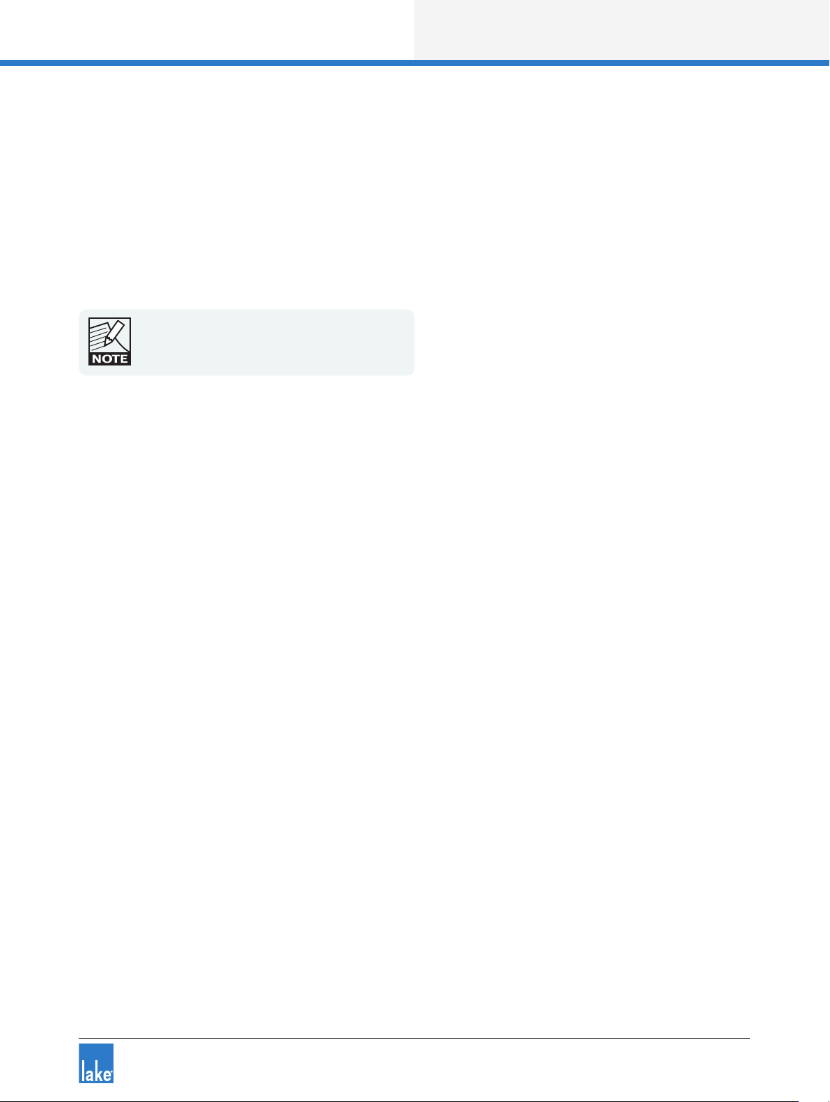
2.1.5 Tablet PC and Laptop Power Settings
When using a wireless laptop or Tablet PC with the Lake Controller, you may need to switch off powersaving features, which can reduce the performance of yourPC.
If you experience slower performance while using the Controller on battery power, turn off any battery
power-saving settings that affect general performance of your PC. Some battery optimizations also affect
wireless connection speed; if you experience a slow wireless connection while in Battery mode, these
settings should be disabled.
To turn off power-saving features, navigate using the Windows Control Panel:
1. Go to Windows Start Menu > Settings > Control Panel > Power Options
2. As settings vary depending on each Tablet or laptop, please consult the appropriate hardware manual
for further information.
7
Page 13
Lake Controller Operation Manual Rev 1.5.9
Software Installation
Figure 2-1: Power Option Properties
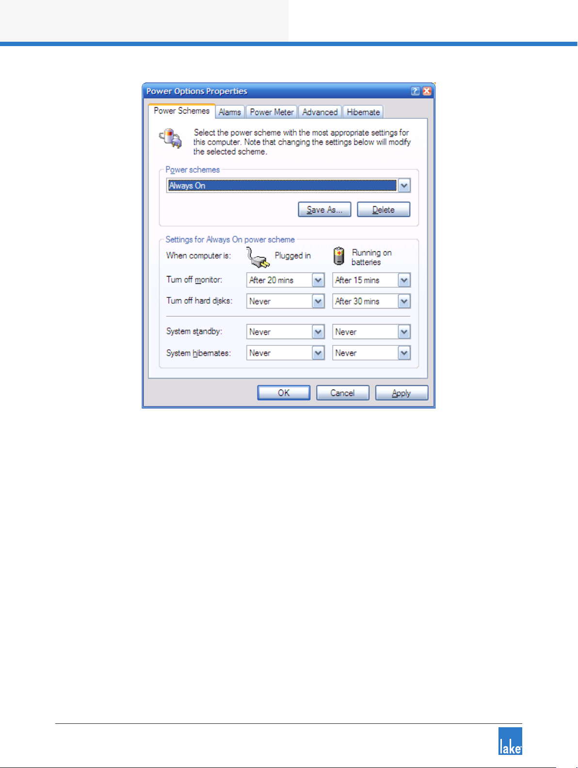
2.1.6 Tablet PC Input Panel Settings
Windows XP Tablet Edition provides the pen action Start Input Panel gesture, which starts the Tablet Input
Panel (keyboard or writing pad). This gesture is a quick movement of the pen from side to side. If the Input
Panel appears while using the Lake Controller, it will cause ickering because both the Controller and the
Input Panel attempt to be in the foreground.
To disable the Input Panel gesture:
1. Access TABLET AND PEN SETTINGS through the Windows Control Panel.
Start Menu > Settings > Control Panel > Tablet and Pen Settings, Pen Options
2. Select PEN OPTIONS.
8
Page 14
Lake Controller Operation Manual Rev 1.5.9
Software Installation
Figure 2-2: Tablet and Pen Settings
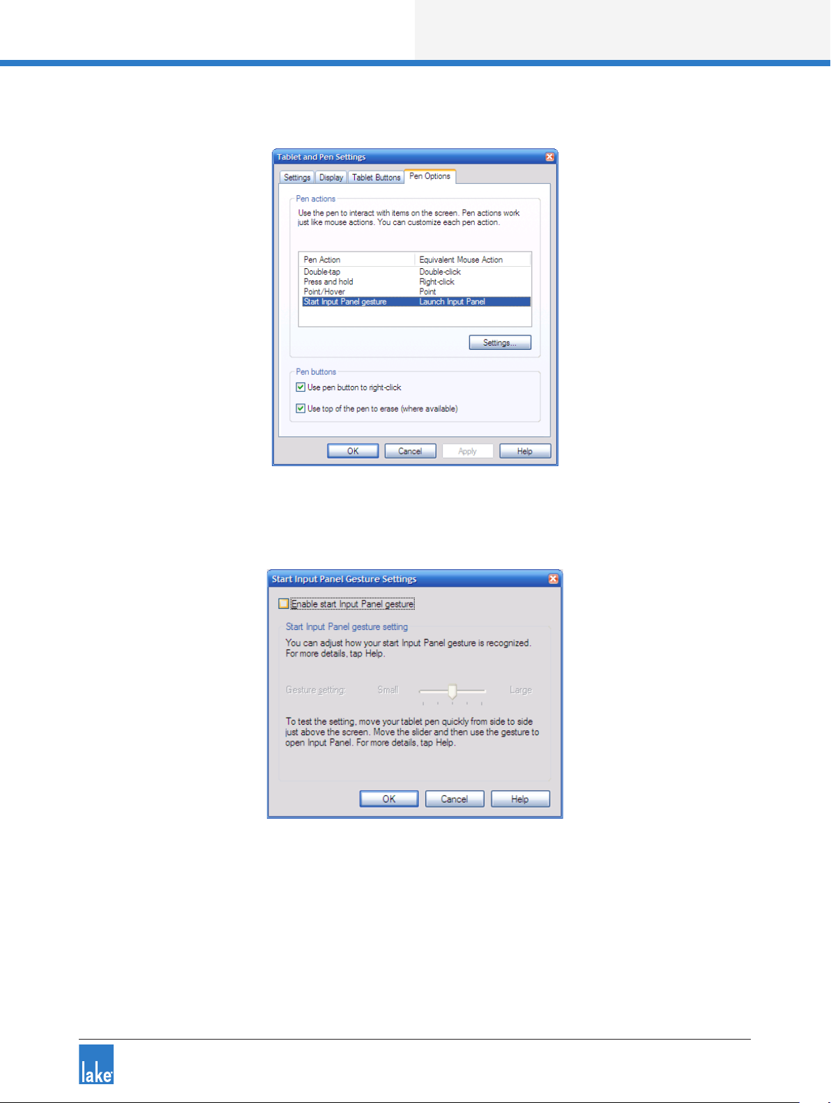
3. Select START INPUT PANEL GESTURE, and tap SETTINGS.
Figure 2-3: Disabling Start Input Panel Gesture
4. Uncheck ENABLE START INPUT PANEL GESTURE.
5. Tap OK.
6. Tap OK again to store your changes.
9
Page 15
Lake Controller Operation Manual Rev 1.5.9
Software Installation
2.2 Lake Controller Installation
2.2.1 First Time Lake Controller Installation
To install the Lake Controller software suite, insert the installer CD-ROM or USB key into your
computer or double-tap the executable installer that was downloaded via the Internet; choose
INSTALL LAKE CONTROLLER then follow the on-screen setup instructions.
1. Read installation information, and tap NEXT to proceed through the installation dialog boxes.
2. Tap INSTALL when requested.
3. Tap FINISH when installation is complete.
Following successful installation, the Lake Controller icon appears on the desktop.
Before using the Lake Controller with a network of
Lake devices, please follow the conguration
procedures described in chapter3.
2.2.2 Overwriting Existing Lake Controller Installation
Overwriting an existing installation requires that both the Installation and Shortcut folders be identical to
those of the existing installation.
If you decide to overwrite your existing installation, ensure that you specify the same location during the
software installation process.
2.2.3 Multiple Lake Controller Installations
If you wish to retain previous versions of the Lake Controller, please ensure that the installation location
specied during software installation is unique.
Only one instance of the software may be used at
any one time. Be aware that different versions of the
software are only compatible with certain rmware
versions.
10
Page 16

Lake Controller Operation Manual Rev 1.5.9
Software Installation
2.3 Moving User Files between Installations
To copy preset les from an existing (old) installation to a new Lake Controller installation.
1. Tap Windows Start > All Programs > Lake Controller vX.X > User Data Files
Where X.X is previous version of the Lake Controller installation.
2. Tap Windows Start > All Programs > Lake Controller vY.Y > User Data Files
Where Y.Y is the latest Lake Controller installation.
3. Use the two Explorer folders that are now visible to transfer user les and folders
between the old and new installations of the Lake Controller.
User Data Files can be accessed in My Documents\Lake\
From Lake Controller v6.3.1 an option is provided to migrate
user data content from v6.3 installations and later
11
Page 17

Lake Controller Operation Manual Rev 1.5.9
Network & Firewall Overview
3. Network & Firewall Overview
This chapter provides an overview of key requirements in terms of rewall conguration, wired and wireless
network conguration, and Dante audio network conguration. The separate Lake Network Conguration
Guide and Dante conguration literature that is included as part of Lake Controller installation should also be
consulted for additional information.
3.1 Ethernet Overview
The TCP/IP protocol suite is structured in layers as illustrated in Figure 3-1. The link layer is Ethernet and is
responsible for connecting to the cabling and Ethernet switches. For communication to occur, each device
must have a valid IP address. The IP layer uses these addresses to route packets between devices. The
transport layer provides ows of data and is used by applications to communicate with each other over the
network.
The Lake Controller uses UDP messaging to communicate with Lake devices on the network. Network
setup and conguration is fast and easy; simply hook up all the devices on the network, and the
Lake Controller software detects and communicates with all devices as required.
Figure 3-1: TCP/IP Protocol Suite
Lake devices are congured to use Automatic Private Addressing which allocates IP addresses from the
range 169.254.x.x. In most scenarios, this automatic allocation setting will not need to be changed. However, if the device is integrated into a sophisticated network conguration, the IP address allocation method
can be changed using the Lake Controller software.
12
Page 18
Lake Controller Operation Manual Rev 1.5.9
Network & Firewall Overview
3.2 Firewall Conguration
3. 2 .1 Overview
By default the Lake Controller Installer creates exceptions for all Lake applications, so manual conguration
should not be required.
If all devices connected to the network are not appearing as expected, it is possible that a rewall is enabled
and is blocking these programs from obtaining network access. Lake applications utilize TCP/IP networking
for Controller and device communication and must be allowed access through any rewall in order to work
correctly.
The Audinate services “common” and “Dante Discovery” must be installed and running for the
Lake Controller Dante functionality to operate, and for the Lake Update utility to function correctly for PLM+
and D Series ampliers. Please ensure these services are allowed full access if requested, or restart to
correct any problems should they occur.
UDP- Broadcast trafc cannot be blocked as it forms
part of the unique device discovery process.
3.2.2 Windows 7 Specic
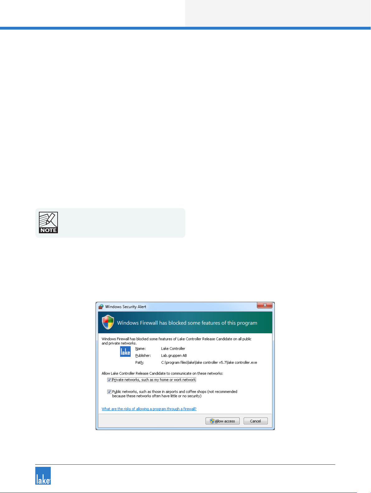
By default, Windows 7 security functions will display a security alert similar to that shown in the rst time
each application is started.
Figure 3-2: Standard Windows Firewall Security Alert
13
Page 19

Lake Controller Operation Manual Rev 1.5.9
Network & Firewall Overview
When using the standard Windows 7 rewall and an alert similar to that shown in Figure 3-2 is displayed:
1. Select checkboxes to allow the Lake Controller (or other Lake application) to access both the Private and
Public networks.
2. Tap Allow Access.
When the Lake Controller or other Lake application opens without this warning, but connected Frames
cannot be identied on the network, the application rewall settings can be veried manually:
1. Type “rewall” into the Windows 7 search feature as shown in Figure 3-3.
2. Select “Allow a program through Windows Firewall” from the list of Control Panel options.
3. Tap Change Settings and locate the Lake application in the list
4. Ensure all checkboxes are marked then tap OK
Figure 3-3: Allow a Program through Windows Firewall (via Win 7 Search)
3.3 IP Address Conguration
The network card of the host computer running the Lake Controller must have a valid IP address to communicate with Lake devices on the network.
By default, Windows computers are congured to obtain an IP address automatically. This default setup
works successfully for most congurations and is the recommended starting point. On an unmanaged
network this option will allocate the PC an IP address from the range 169.254.x.x.
14
Page 20

Lake Controller Operation Manual Rev 1.5.9
Network & Firewall Overview
If using automatic IP address allocation, please ensure your Ethernet switch and/or Lake devices are turned
on and connected to your PC for a minute or so (Windows XP - generally faster on Windows 7) before starting the Lake Controller. This allows Windows time to correctly identify your PC’s IP address, and therefore
allows the Lake Controller to communicate properly when it scans the network.
If you are on a managed network (such as a corporate network) with a DHCP server and you are having
communication problems, it is recommended that you change the IP addressing mode on the devices to
use DHCP. Please consult a network specialist if you have trouble with complex network congurations.
A xed IP address is useful if you are frequently switching between network adapters, or unplugging and
reconnecting your network cable. The automatic IP address allocation used by Windows requires a valid
network to be present, and can take up to one minute for the PC to discover its IP address. In this case it
is recommended that you try using a xed IP address in the same subnet as that used by default address
allocation (i.e. 169.254), but using the reserved ranges of either 169.254.0.x or 169.254.255.x.
The IP address ranges 169.254.0.x and 169.254.255.x are
reserved by IANA so future use of these address ranges cannot
be guaranteed.
You can specify a xed IP address by following these steps in Windows 7:
1. Tap the Windows Start icon, type “network” in the search bar then tap NETWORK AND SHARING
CENTER from the options listed under the Control Panel heading as shown in Figure 3-4.
Figure 3-4: Opening Windows Network and Sharing Center
15
Page 21
Lake Controller Operation Manual Rev 1.5.9
Network & Firewall Overview
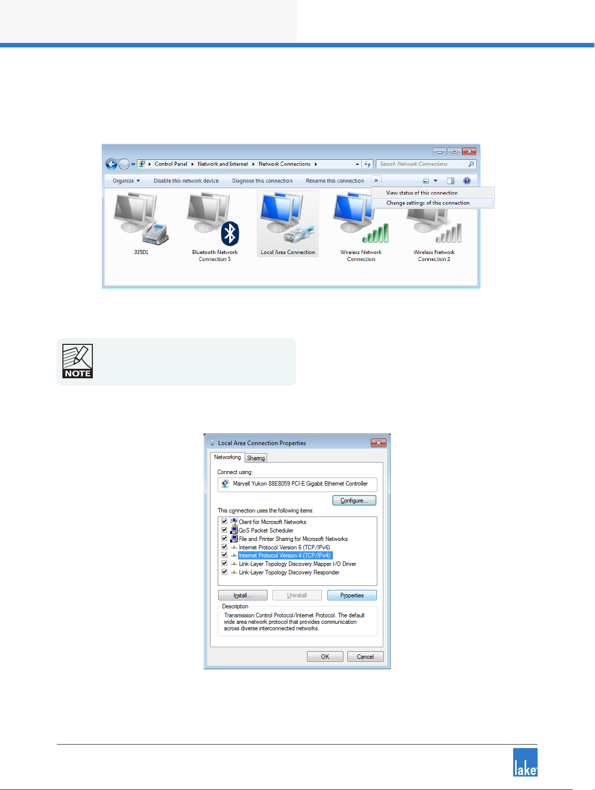
2. Select the appropriate network connection (Local Area Connection or Wireless Network Connection) to
congure, then select “Change settings of this connection” as shown in Figure 3-5.
Figure 3-5: Selecting Wired Network Connection
Although this tutorial uses Local Area Connection as
an example, the principles also apply to Wireless
Network Connection.
3. Select INTERNET PROTOCOL VERSION 4 (TCP/IPV4), and tap the PROPERTIES button.
Figure 3-6: Local Area Connection Properties
16
Page 22

Lake Controller Operation Manual Rev 1.5.9
Network & Firewall Overview
4. Select “Use the following IP address,” enter an IP address, tap TAB or tap in the Subnet mask box to
auto-populate with the correct mask.
Figure 3-7: TCP/IPv4 Properties
5. Tap OK to apply changes, and exit Internet Protocol (TCP/IP) Properties.
6. Tap OK to apply changes, and exit Local Area Connection Properties.
Please refer to Chapter 28 for more information on
the selection of an appropriate IP address.
3.4 Wired Network Setup
3.4 .1 Overview
The Lake Controller host computer can be connected directly to any Lake device through the Ethernet connectors. Multiple devices can be connected by cascading connections between units, although this is not a
recommended solution for the successful use of Dante™ (Digital Audio Networking via Ethernet). Connecting
devices via a good quality external Ethernet switch with QoS is highly recommended. Please refer to tutorial
section 4.3.6 for further information regarding Dante, and section 3.6.4 for details on using QoS with Dante.
The Lake Controller can be connected to a network of Lake devices using a wired or wireless Ethernet
solution. A wired network is a simpler, faster and more robust solution and should be implemented where
possible in preference to using a wireless system. Additionally, when implementing Dante audio networking
in conjunction with a wireless access point for Lake Controller data, additional conguration of an external
17
Page 23

Lake Controller Operation Manual Rev 1.5.9
Network & Firewall Overview
Ethernet switch is required to lter Dante audio trafc from reaching the access point. Please refer to
section 3.6.3.
The Controller can connect anywhere on a network of Lake devices. LEDs next to each port ash to conrm
valid communication. Please connect the Controller computer to the network with an Ethernet cable, and
follow the verication steps in the next section.
3.4.2 Verifying Wired Controller and Device Communication
Once the network is connected, follow these steps to conrm communication between the Lake Controller
and Lake devices:
1. Double-tap the Lake Controller shortcut icon from the Windows desktop. The SELECT NETWORK
Adapter dialog box (shown) appears if your computer has more than one network interface enabled.
This typically occurs if your PC has both wired and wireless network interfaces.
Only one network adapter should be enabled on your PC when
using the Lake Controller. Network adapters can be disabled via
the Windows Network and Sharing Center > Change Adapter
Settings.
2. Select the Ethernet adapter currently used for the network (the wired adapter for this example).
Figure 3-8: Select Network Adapter
When the Controller begins, you will be prompted with a dialog box asking whether to load the last conguration.
3. Tap NO to this dialog. The Main page of the Controller is displayed.
4. To verify that the devices are on the network and communicating, tap the Modules button.
The Module scroll bar will be displayed.
18
Page 24

Lake Controller Operation Manual Rev 1.5.9
Network & Firewall Overview
Figure 3-9: Module Scroll Bar
The folder to the left of the Module scroll bar provides Virtual Frames, which are always available whether or
not the network is connected. Virtual Frames allow you to create a complete system conguration ofine.
If your network connections are valid, all devices connected to the network appear on the Module scroll bar
to the right of the Virtual Frames.
Figure 3-9 shows the Module scroll bar, which visually identies the number of Modules within each Frame
on the network. The number of Modules within a Frame depends on the device type/conguration. Modules
shown with a circle are available on the network, but not currently in use; Modules identied with text
only are already in use in the current system conguration. Please refer to the tutorial in chapter 4 for more
information on Modules and Frames.
3.5 Wireless Network Setup
3.5 .1 Overview
Several hardware manufacturers supply wireless networking solutions that adhere to the various 802.11
wireless Ethernet standards. This means that any standard Ethernet 802.11 wireless networking solution
should work with this network system.
When using a wireless access point on the same network as Dante digital audio, an approved external
Ethernet switch must be congured to lter Dante audio packets from reaching the wireless network.
Please refer to section 3.6.3 for further information.
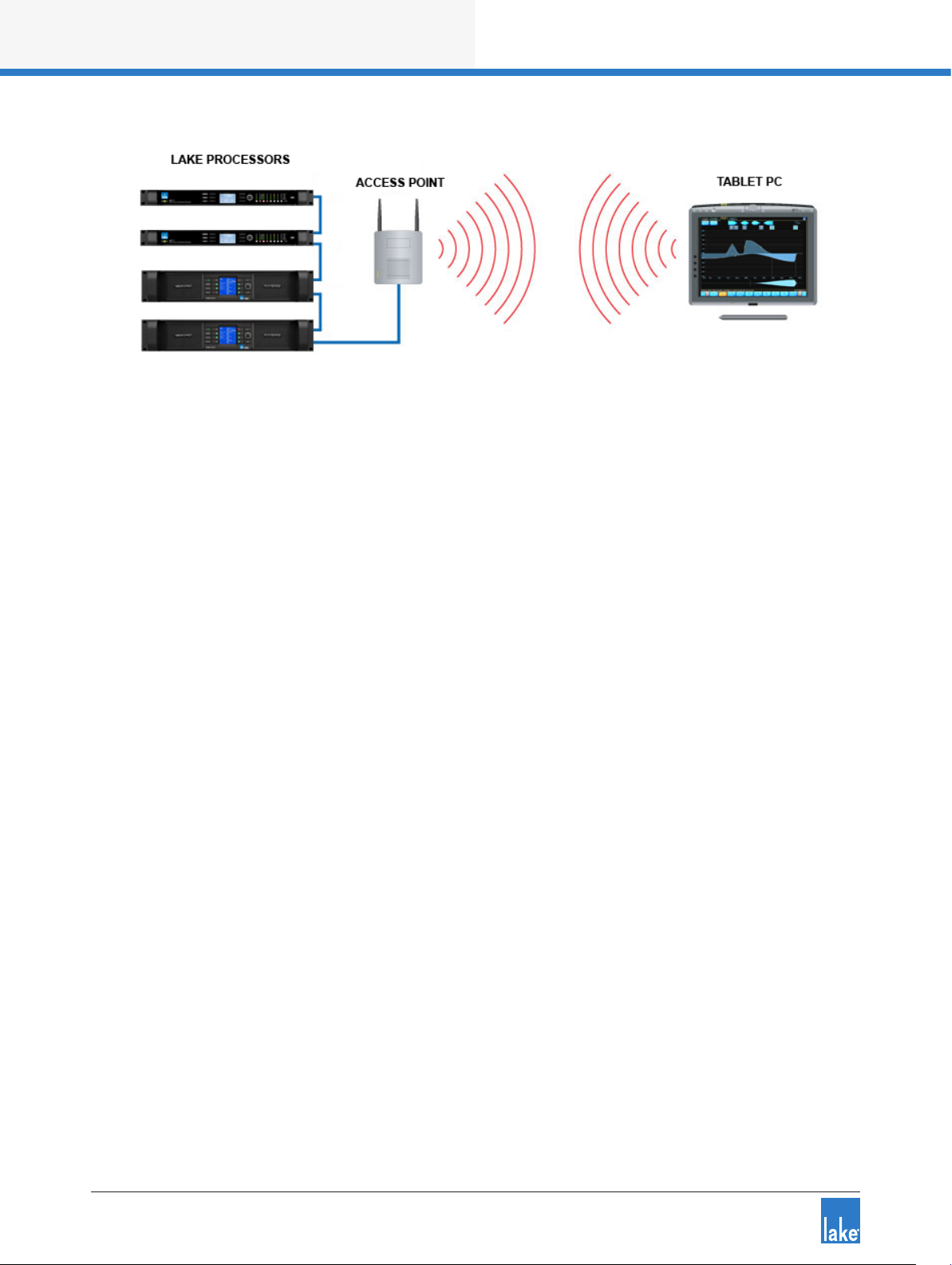
An access point is used in a wireless Ethernet network conguration to connect Lake devices to the
Lake Controller host computer. The access point is connected to the wired network using standard Ethernet
cables. It performs the same function as a switch: receiving, buffering, and transmitting data between wired
and wireless networks.
19
Page 25
Lake Controller Operation Manual Rev 1.5.9
Network & Firewall Overview
Figure 3-10: Basic Wireless Setup (Not Suitable for Use with Dante or larger networks)
Ideally, the procedure just described yields a perfectly functional and secure system. However, there are
two complications: Some environments have additional wireless network systems and communications
equipment competing for the same airspace used by the Lake system. It is also important to provide security so another wireless network cannot access this network system.
As part of the 802.11 standard, various levels of access control and encryption exist. There are also different
communication channels that operate at different frequencies.
The service set identier (SSID) controls access to this wireless network by functioning as a password or
key between wireless network devices to differentiate them from each other. The SSID must be exactly the
same on all wireless devices (the access point and all Controller host computers). The SSID is case sensitive.
Although the SSID differentiates among wireless systems, it does not provide security to the network.
Wired Equivalent Privacy (WEP) is a security protocol for wireless networks dened in the 802.11 standard.
The WEP protocol provides the same level of security as a wired network by encrypting data over radio
waves to protect it during transmission. It is recommend that WEP encryption is enabled if other computers
are connected to your Ethernet network.
3.5.2 Conguring the Tablet PC for Wireless Networking
Assuming that the wireless access point has been set up appropriately and is turned on, we now need to
congure the Tablet PC to connect to this access point.
1. Navigate to the Windows Network and Sharing Center as shown in Figure 3-4.
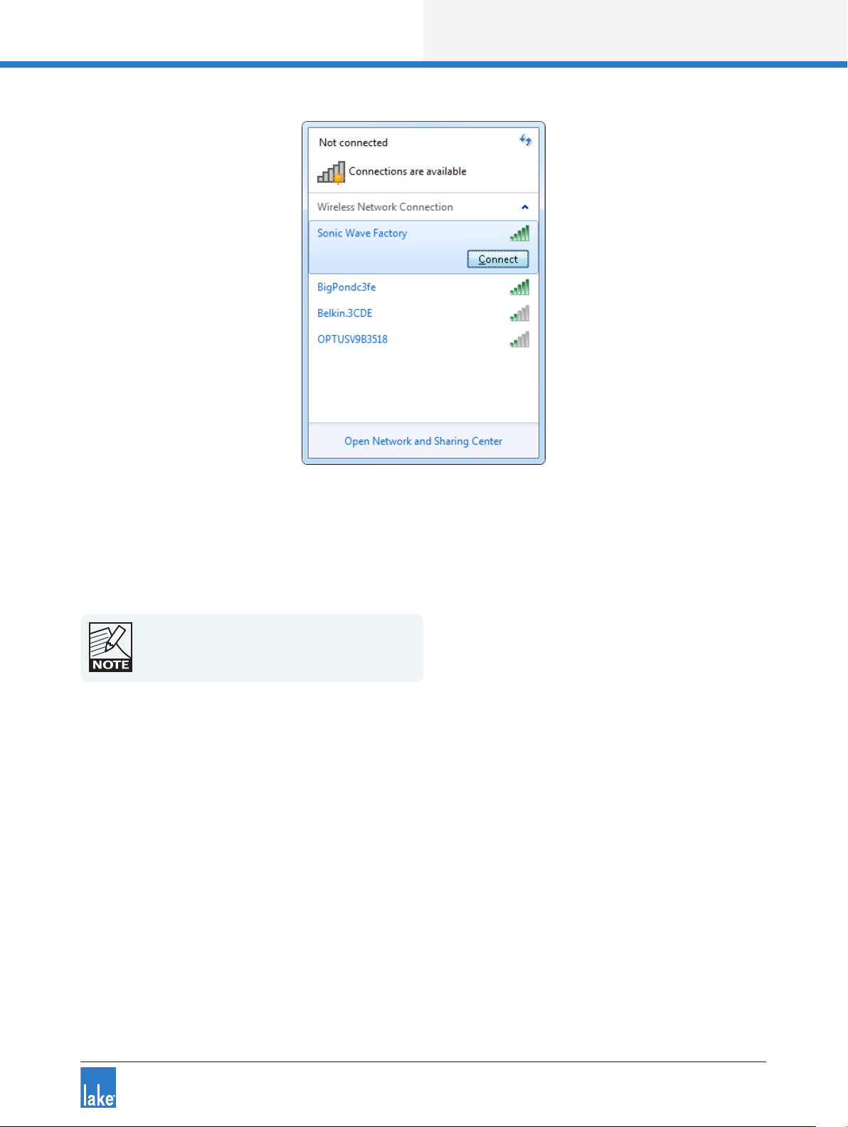
2. Tap the wireless signal strength icon at the bottom-right of the screen in the Windows notications
area and select the wireless access point from the list that appears and tap CONNECT as shown in
Figure 3-11.
20
Page 26
Lake Controller Operation Manual Rev 1.5.9
Network & Firewall Overview
Figure 3-11: Connecting to a wireless access point
3. Enter the network security key, or press the button on the wireless access point if requested.
4. If you encounter network problems when using the default automatic IP address allocation (more likely
with Windows XP), please setup a xed IP address as described in section 3.3.
Please refer to chapter 28 for more information on
the selection of an appropriate IP address.
3.5.3 Conrming Wireless Operation of the Lake Controller
To conrm wireless operation:
1. Double-tap the LAKE CONTROLLER icon to start the software. If you have more than one network
adapter enabled, the SELECT NETWORK ADAPTER dialog box will be displayed; select the
WIRELESS NETWORK ADAPTER.
2. Tap NO when asked whether to recall the last conguration. A brief resync message will appear for
each Lake device on your network, conrming that your network connection is operating properly.
3. Tap MODULES. Each online device is represented on the Module scroll bar by a number of Module
icons surrounded by a border.
4. Tap QUIT CONTROLLER to exit.
21
Page 27

Lake Controller Operation Manual Rev 1.5.9
Network & Firewall Overview
3.6 Dante Digital Audio Networking
Dante provides multi-channel digital audio networking over standard a standard Ethernet network, alongside
control data for the Lake network. Various topics relating to network conguration are summarized in this
section; for further details please refer to associated Dante literature available via:
Start > All Programs > Lake Controller vX.X > Documentation > Dante Documentation after installing the
Lake Controller software.
Additional Dante product information is available at the Audinate website: http://www.audinate.com/
3.6 .1 Dante Controller Compatibility
All devices are compatible with Audinate’s Dante Controller software (not applicable for MY8-LAKE)
Changes made via the Lake Controller will be reected in the Dante Controller and vice-versa:
▸ When both the Lake Controller and Dante are active, changes will synchronize immediately across both
software controllers and affected devices.
▸ When Dante-related parameters are changed via the Lake Controller while the Dante Controller is
disconnected or closed, the Dante Controller will inherit the change the next time it is connected or
opened.
▸ When Dante-related parameters are changed via the Dante Controller while the Lake Controller is
disconnected or closed, the Lake Controller will identify the Frames as Out of Sync the next time it is
connected, or opened using the Recall Last System Conguration option.
3.6.2 Dual Redundant Network Conguration
With dual redundancy activated, the Controller can be connected to the secondary network connection
using an IP address in the range 172.31.x.x. on the Lake Controller computer. This conguration allows for
fail-over to the secondary network should a problem occur with the primary network.
Do not connect Controllers to the primary and
secondary network connections simultaneously.
3.6.3 Using Dante with Wireless Data Control or Low-Bandwidth Devices
Dante (Digital Audio Networking) technology requires a reliable 100 Mbps (or faster) network to operate, and
therefore cannot operate via a wireless transmitter/receiver. However, in most Lake networks, it is likely that
22
Page 28

Lake Controller Operation Manual Rev 1.5.9
Network & Firewall Overview
wireless control of the Lake devices will be required on the same network that is transmitting and receiving
Dante digital audio signals.
To achieve this, you must congure the Ethernet switch on the boundary of the wireless network to lter
Dante trafc from reaching the wireless access point or other lower bandwidth devices (e.g. legacy devices
such as the Contour Pro 26 or Mesa Quad EQ), or you will most likely experience communication problems.
The diagram below summarizes the desired outcome from correctly conguring your Ethernet switch to
lter Dante audio packet
Figure 3-12: Using Dante with Low Bandwidth devices
Please refer to the Audinate
ACL packet ltering. This document is available via:
Start > All Programs > Lake Controller vX.X > Documentation > Dante Documentation after installing the
Lake Controller software.
Additional Dante product information is available at the Audinate website: http://www.audinate.com/
®
document AUD-ANO-ACL Filtering SRW224G4 for further details regarding
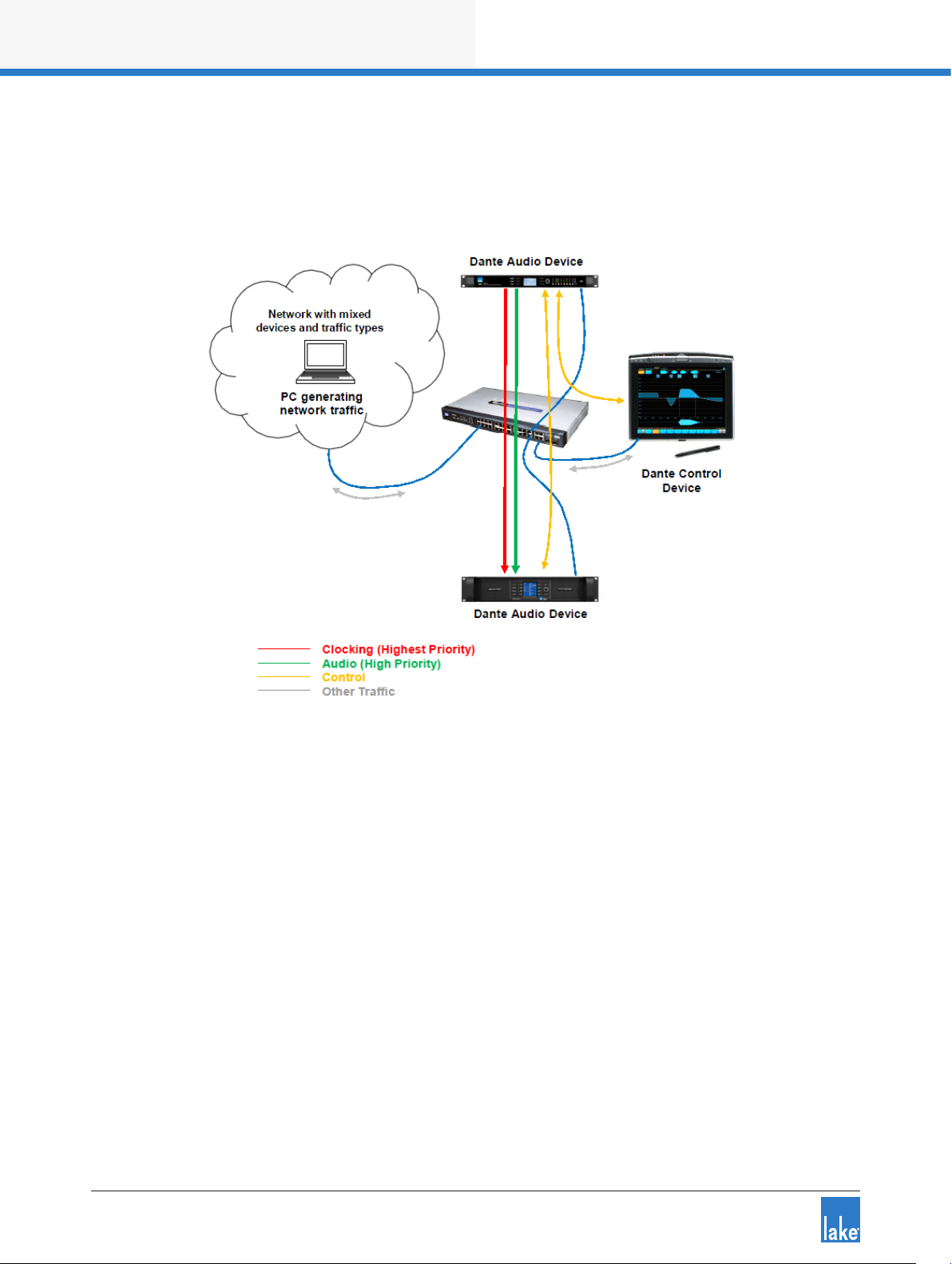
3.6.4 Dante with Quality of Service Ethernet Switches
The use of an external Ethernet switch with QoS (Quality of Service) is strongly recommended when using
Dante digital audio over your Lake network. Dante uses standard network QoS techniques available in
off-the-shelf Ethernet switches to prioritize clocking and audio trafc, and to allow non-Dante devices such
as personal computers to share a single network with Dante devices. The diagram below shows the order of
priority given to the different types of data packets going through the switch. Using a switch without QoS,
23
Page 29
Lake Controller Operation Manual Rev 1.5.9
Network & Firewall Overview
or with QoS turned off on a busy network, may result in audio packets arriving too late to be played out,
resulting in audio glitches.
Figure 3-13: Dante Quality of Service Switch Conguration
Please refer to the Audinate document AUD-ANO-QoS Switch Conguration for further details regarding
ACL packet ltering. This document is available via:
Start > All Programs > Lake Controller vX.X > Documentation > Dante Documentation after installing the
Lake Controller software.
Additional Dante product information is available at the Audinate website: http://www.audinate.com/
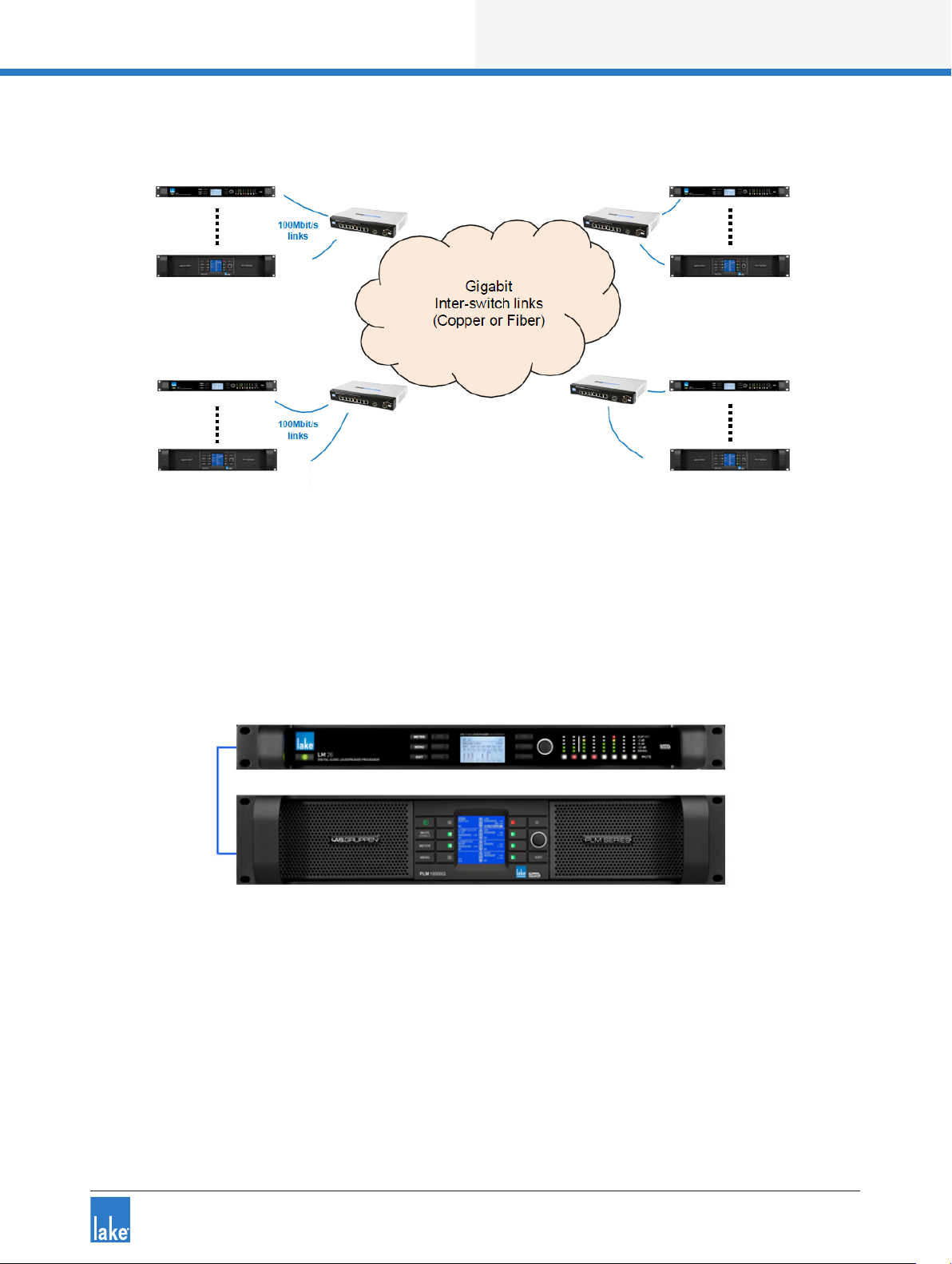
3.6.5 Recommended Network Topologies When Using Dante
The use of an external Ethernet 100 Mbps switch with QoS (Quality of Service) is highly recommended. It
is also recommended that each device has its own direct connection to that switch. Where switches are
connected together, this should be achieved via a gigabit ber or copper connection.
24
Page 30
Lake Controller Operation Manual Rev 1.5.9
Network & Firewall Overview
Figure 3-14: Recommended Network Topologies
Two Lake devices may be daisy chained together and run Dante. The recommended latency when connecting two Lake devices in this manner is 0.8 ms.
Figure 3-15: Only two Lake devices may be daisy chained for use with Dante
More than two Lake devices should not be daisy chained together when Dante is being used.
25
Page 31

Lake Controller Operation Manual Rev 1.5.9
Network & Firewall Overview
Figure 3-16: Do not daisy chain more than two Lake devices when using Dante
The use of Dante across wireless networks as shown below is not supported.
Figure 3-17: Do not use Dante across wireless networks
Please refer to the Audinate document AUD-ANO-QoS Recommended Network Topologies for further
details regarding ACL packet ltering.
This document is available via:
Start > All Programs > Lake Controller vX.X > Documentation > Dante Documentation after installing the
Lake Controller software.
Additional Dante product information is available at the Audinate website: http://www.audinate.com/
26
Page 32

Lake Controller Operation Manual Rev 1.5.9
Lake Controller Tutorial
4. Lake Controller Tutorial
This tutorial will help you start using the Lake Controller software quickly and easily by providing an overview of common features. There are many underlying details not covered in this tutorial, so please refer to
the other sections of this manual for detailed reference information.
The tutorial uses the Lake LM 26 (Contour Mode) & LM 44 (Mesa Mode) these are the two main types
of Modules that are available across Lake-enabled devices. You may however follow this tutorial with any
product; most features and functionality are common across all products.
4.1 Starting the Lake Controller
To start the Lake Controller:
1. Double-tap the Lake Controller software icon located on the Microsoft® Windows® desktop.
2. Tap NO in the dialog box asking if you would like to recall the last conguration.
Tapping YES recalls the conguration in use prior to
exiting the last Lake Controller session. A comparison occurs and any differences are highlighted for
online Modules. Audio processing is not affected.
The Main page appears and is in its default, blank state.
Figure 4-1: Main Lake Controller HOME Page
27
Page 33

Lake Controller Operation Manual Rev 1.5.9
Lake Controller Tutorial
4.2 Overview of Main Page Components
This section covers the various components shown on the main page.
4. 2.1 Button Bar Interface
The button bar, located at the bottom of every page in the software, is used to navigate through and activate
the Lake Controller features and functions. Three colors indicate the button status:
▸ ORANGE - currently selected menu or function
▸ BLUE - available menu or function based on current selection
▸ GRAY - currently unavailable menu or function
Figure 4-2: Context, Scroll and HOME Buttons
The button with the numbered arrows pointing upward shown in Figure 4-2 is the CONTEXT button, which
enables fast system navigation. Contexts allow you to jump directly from one view to another view without
having to use the tool bar for navigation. For further detail, please refer to section 13.1.
The button with arrows pointing right is active when a page or menu scroll bar contains more information
than can be displayed on the width of the screen. Tap this button to move the scroll bar, pages, or overlay
tabs to the right, revealing additional data.
The HOME button is available from almost all menu levels, and returns you to the Main page of the system.
Figure 4-3: Scroll and Undo Buttons
The scroll and undo buttons shown in Figure 4-3 are available on the right side of the button bar and may be
active or deactive depending on the screen being viewed. The button with arrows pointing left moves the
scroll bar, pages, or overlay tabs to the left.
The button labeled UNDO (or REDO after UNDO has been used) provides a single-level UNDO/REDO
function for adjustments made to EQ/levels and crossovers (where applicable).
Generally, labels on buttons describe the open submenu or the function performed by tapping the button.
28
Page 34

Lake Controller Operation Manual Rev 1.5.9
Lake Controller Tutorial
4.2.2 Help and Status Messages
Context-sensitive help is displayed above the button bar on the left.
Figure 4-4: Context Level Help
System status messages are displayed above the button bar on the right. In the following example, the
network status is shown to be ofine.
Figure 4-5: Network Status Messages
4.2.3 Pa ge Tabs
At the top left of the user interface, the MAIN and ALL pages are presented. The MAIN page is the default
page ready to use. The ALL page provides monitoring of up to 260 Modules on a 1,024 × 768 pixel screen
without scrolling. It displays a status summary for each Module, with additional status information for
Lab.gruppen ampliers. More pages can be added as required to logically partition your system.
Figure 4-6: Example Page Tabs
For further details, please refer to section 8.7.
4.2.4 Minimizing the Lake Controller
To minimize the Lake Controller software and return to Windows, tap the Lake icon in the top-right corner
of any screen. When running in Windowed-mode, minimize the controller using the standard Windows
minimize button.
Figure 4-7: Use the Lake logo (top right of screen) to minimize the Lake Controller
This icon is animated. It rotates when the software is performing any function that requires the user to wait
for data to be transferred or for a processing to complete.
29
Page 35

Lake Controller Tutorial
4.3 Modules and Frames
4. 3 .1 Overview
A Frame represents one physical Lake device on the network. Multiple Modules are contained within
each Frame. The number of Modules available for a given device is dependent upon the signal processing
conguration/capabilities of the device.
PRODUCT CONFIGURATION NUMBER OF MODULES
D 200:4L 4x4 Power Amplier 4 Contour Modules
D 120:4L 4x4 Power Amplier 4 Contour Modules
D 80:4L 4x4 Power Amplier 4 Contour Modules
D 40:4L 4x4 Power Amplier 4 Contour Modules
D 20:4L 4x4 Power Amplier 4 Contour Modules
D 10:4L 4x4 Power Amplier 4 Contour Modules
PLM+ 20K44 4x4 Power Amplier 4 Contour Modules
PLM+ 12K4 4 4x4 Power Amplier 4 Contour Modules
PLM+ 5K44 4x4 Power Amplier 4 Contour Modules
PLM 20000Q 2x4 Power Amplier 2 Contour Modules
PLM 14000 2x2 Power Amplier 2 Contour Modules
PLM 10000Q 2x4 Power Amplier 2 Contour Modules
2x6 Loudspeaker Processor 2 Contour Modules
Lake LM 26
4x4 System Equalizer 4 Mesa Modules
4x4 System Equalizer 4 Mesa Modules
Lake LM 44
2x6 Loudspeaker Processor 2 Contour Modules
4x12 Loudspeaker Processor 4 Contour Modules
MY8-LAKE
Table 4-1: Overview of Lake Devices and Module Configurations
8x8 System Equalizer 8 Mesa Modules
2x6 Loudspeaker Processor +
4x4 System Equalizer
2 Contour Modules
+ 4 Mesa Modules
Figure 4-8 shows the Module scroll bar displaying Virtual Frames for Lake-enable devices, after accessing
the Virtual Frame folder.
30
Lake Controller Operation Manual Rev 1.5.9
Page 36

Lake Controller Tutorial
Figure 4-8: Module Scroll bar
Figure 4-9 shows the Module scroll bar displaying Virtual Frames for Lake-enable devices, after accessing
the Virtual Frame folder.
Figure 4-9: Module Scroll bar - Virtual Frames
To place an online Frame in the work area for use during this tutorial:
1. Tap the Module button to display the Module scroll bar as shown in Figure 4-9
2. Tap one of the gray circles (which indicates an available online Frame)
The cursor takes on the form of the selected frame.
3. Place the selected Frame in the work area by tapping in the required location.
An LM 26 (Contour Mode) and an LM 44 (Mesa Mode) are used for most examples in this tutorial; the
resulting screen will look similar to that shown in Figure 4-10, depending on the product you are using.
Lake Controller Operation Manual Rev 1.5.9
31
Page 37

Lake Controller Operation Manual Rev 1.5.9
Lake Controller Tutorial
Figure 4-10: LM 26 Frame Placed in Main Work area
4.3.2 Module Icons
Each Module icon provides conguration information as shown in Figure 4-11.
Figure 4-11: Module Icon Components
▸ Module ID - Identies a particular Module within the device, represented by this icon.
▸ Frame Label - Identies the Frame (device) associated with this icon by a user-dened label that also
appears on the front panel of the device.
▸ Module Type - Identies the number of output channels or an abbreviation of a Module type description
(MEq for a Mesa EQ Module).
▸ Module Label - User-dened label that describes the Module’s use or speaker type.
▸ Module Selection and Clip Indicator - The Module icon border is yellow to indicate the Module is
selected. If it ashes red, a channel on that Module is clipping.
32
Page 38

Lake Controller Operation Manual Rev 1.5.9
Lake Controller Tutorial
▸ Power Output Mute Indicator (Lake-enabled ampliers only) - A red bar indicates the power output
channel is muted; a blue bar indicates it is unmuted. This indicator appears on the Module from where
the channel is routed.
▸ Input Mute Indicator - If the central round part of the icon is red, the input is muted; if the icon is blue,
the input is not muted.
▸ Output Mute Indicators - Displayed as small red bars when the outputs are muted and are absent if
unmuted. The number of mute indicators depends on the number of output channels in the selected
Module type.
▸ Module Label - Displays the label for the Module, in this case a default Classic 3-Way. For further
details on Module label abbreviations and an explanation on Module types, please refer to chapter 9.
4.3.3 Selecting and Moving Icons
Multiple icons may be selected (via the MODULES, GROUPS, PAGES, and ICON CONTROL menus),
providing a faster solution to Graphical arrangement of the work area. For example, multiple icons can be
dragged back to the scroll bar, moved around on screen, or dragged to another page tab.
This example uses an LM 26 (Contour Mode) and an LM 44 (Mesa Mode) for demonstration purposes; the
logic remains the same for all types of Group, Module, and Super Module icons.
1. Drag a box around the icons you wish to move.
Figure 4-12: Click and drag around Module icons
2. Release the pen (or mouse); icons inside the yellow rectangle are now selected.
Figure 4-13: Yellow border snaps to selected Module icons
33
Page 39

Lake Controller Operation Manual Rev 1.5.9
Lake Controller Tutorial
3. Tap inside the yellow box, and drag it to the new area.
4. Release the pen (or mouse); the icons are now deselected.
Figure 4-14: Dragging multiple Module icons
Figure 4-15: Release to deselect Module icons
To drag icons to a new page, select the icons you wish to move and then drag them over the page’s tab at
the top. That page will be automatically selected. You may then place the icons where required.
4.3.4 Labeling Frames and Modules
The Frame label initially shows the product code (e.g. 10000Q) which varies depending on the device. The
Frame label is the same on all Modules in the Lake Controller, and on the front panel of the associated
device. The Frame label helps to identify the physical location of a device on the network.
To label a Frame:
1. Tap the A Module to select it.
A yellow border surrounding the Module icon indicates it is selected.
If a Module is not selected, most of the button bar
functions are gray to signify they are inactive.
2. Tap LABEL & LOCK.
3. Tap LABEL FRAME to display the on-screen keyboard.
34
Page 40

Lake Controller Operation Manual Rev 1.5.9
Figure 4-16: On-screen keyboard
4. Type ‘Demo’ using the on-screen (or external) keyboard, and tap OK.
The Frame label eld for the Frame’s Modules displays ‘Demo’.
Lake Controller Tutorial
Figure 4-17: Changing the Frame Label
Now let’s assign a name to the A Module:
5. Tap the A Module to select it.
6. Select LABEL MODULE from the button bar.
7. Name this Module ‘My 3-Way’ using the on-screen keyboard, and tap OK.
8. Tap LABEL EXIT to return to the MODULES menu.
Figure 4-18: Labelling a Module
To label a Super Module, select it in the work area
and tap LABEL SUPERMOD.
35
Page 41

Lake Controller Operation Manual Rev 1.5.9
Lake Controller Tutorial
4.3.5 I/O Cong
This section assumes the use of classic routing
mode; all providing extensive I/O routing options.
The MY8-LAKE in simplied view provides a xed
output cong.
1. Tap the I/O CONFIG button to display the block diagrams of each Module in the Frame.
Figure 4-19: LM 26 I/O Conguration Screen
The right side of the I/O CONFIG page can be dragged to scroll up and down for viewing of all Module block
diagrams where all diagrams cannot t on the screen.
2. Tap any black space within the block diagram area and drag up or down to scroll. The I/O CONFIG page
is interactive; each blue processing block can be selected to directly access the relevant screen in the
software. Each block diagram has a front-end input mixer.
3. Tap any one of the four inputs of the ‘My 3-Way’ Module to access the input mixer.
36
Page 42

Lake Controller Operation Manual Rev 1.5.9
Lake Controller Tutorial
Figure 4-20: Four-Channel Input Mixer
The number of inputs preset in the input mixer is relevant to the number of inputs available simultaneously
for the device / module combination, and allows the inputs to be selected or mixed together appropriately.
4. Tap the exit button in the bottom-right corner of the Input Mixer pop-up window to return to the
I/O CONFIG screen.
Each output can be custom congured by the user. Tap one of the zoom icons (represented by a magnifying glass) on the right side of the Module’s block diagram. This action will open the Output Conguration
window.
37
Page 43

Lake Controller Operation Manual Rev 1.5.9
Lake Controller Tutorial
Figure 4-21: LM 26 Output Conguration
The Output Conguration window provides the ability to route any physical input or Module output to any
available analog or digital output on the device. The arrows below the source and destination labels allow
selection and mapping of all available I/O.
LM Series devices provide the ability to route any of the eight the Input Router Outputs directly to any
output. This allows fail-over input switching to be congured for pass-thru / format conversion purposes. For
instance, an input router can be congured for fail-over to Analog if AES input fails, and the whichever audio
is used can be passed through to Dante (or any other output type). For further information, please refer to
section 21.1.
5. Tap the blue EXIT/RETURN button in the bottom right to return to the I/O CONFIG page.
The left side of the I/O CONFIG summary screen provides both clock and INPUT CONFIGURATION functions along with other Frame specic functionality. Status information is provided, and zoom icons open
pop-up windows for access to conguration parameters.
Lake devices have sophisticated digital clocking systems, allowing selection between internal and external
clock sources at all standard audio sample rates. By default, all Lake devices (except the MY8-LAKE) use
38
Page 44

Lake Controller Operation Manual Rev 1.5.9
Lake Controller Tutorial
an internal clock operating at 96 kHz. You can choose to use any available external clock source using the
interface provided by the clock source conguration window.
Figure 4-22: LM 44 Digital Clock Conguration
The current Primary Clock Source is shown on the top left of the screen, and the current Sample Rate
Converter Clock Source is shown on the top right. You can choose any available clock source using the
Clock Source Selector scroll bar at the bottom of this window. The Inputs/Outputs tab are available on some
products providing quick access to set unique digital clocks for specic inputs and outputs.
Please refer to each product’s Operational manual for further details on clocks, clock source priorities,
sample-rate converters, and signal processing latency the product.
The INPUT CONFIGURATION pop-out window allows exible routing of all available inputs to each Input
Mixer channel along with a four-level auto-select priority allocation for each input, as shown in Figure 4-23.
39
Page 45

Lake Controller Operation Manual Rev 1.5.9
Lake Controller Tutorial
Figure 4-23: LM 44 Input Conguration Screen
From this interface, you can allocate which input is used for each input channel of the Input Mixer, and in
which order up to four inputs should auto-select (fail over) for each input channel.
The input AUTOSELECT feature allows you to set up a redundant system. The device will attempt to use
the rst signal; if the rst signal is unavailable it will try the second, third, and fourth signals.
Tapping DISPLAY DETAILS allows control of digital clock selection/digital gain offsets and analog input
headroom as shown in Figure 4-24.
DIGITAL GAIN OFFSET allows ne-tuning of gain between different digital and analog signals to allow for a
seamless transition between the signal sources.
40
Page 46

Lake Controller Operation Manual Rev 1.5.9
Lake Controller Tutorial
Figure 4-24: LM 44 Input Conguration - Details View
The next summary item on the left side of the I/O CONFIG screen (LM Series devices only) is
GPIO Conguration. Tapping this icon, or the summary text, will display the screen shown in Figure 4-25.
Figure 4-25: GPIO Conguration (LM Series Devices Only)
GPIO Conguration is used to set the actions for this contact-closure style external control interface. For
further details, please refer to the LM Series Operation Manual and to section 8.2.3 in this document.
41
Page 47

Lake Controller Operation Manual Rev 1.5.9
Lake Controller Tutorial
The last item on the left side of the I/O CONFIG page allows remote control of Iso-Float™. This powerful
feature allows you to troubleshoot grounding issues remotely from the Controller.
Figure 4-26: Analog Iso-Float Status Screen
The ANALOG ISO-FLOAT STATUS window shows you the current state of the device hardware and allows
you to make changes to the grounding state of each analog converter card.
After closing the ANALOG ISO-FLOAT STATUS pop-up window, return to the Main page by tapping the
HOME button.
4.3.6 Dante
Dante audio networking technology from Audinate provides a hassle-free digital audio networking solution
for Dante-enabled Lake devices providing reliable, sample-accurate, low-latency audio distribution over
Ethernet.
Dante provides a reliable, digital-audio networking system with complete exibility, ease of use, and
cost-effectiveness. With innovative features such as Zen™, Dante-enabled Lake devices automatically nd
each other and also allow any Dante audio channel on the network to be routed to the input of one or more
devices.
Dante can be easily integrated into an existing network, sharing the system with normal data trafc. Dante
also offers a virtual sound card feature for audio recording, processing or playback using computer-based
programs. This feature is enabled by plugging into the standard Ethernet port on a PC; no external boxes or
sound cards are required.
On Dante-enabled Lake devices no additional hardware is required; a single Ethernet connection can transmit all audio and control data. Table 8-3 on page 136 summarizes the number of Dante input and output
channels per Lake product, along with an indication of whether the product provides dual redundant Dante
audio networking which as described in section 3.6.2, and the associated Product Operation manuals.
42
Page 48

Lake Controller Operation Manual Rev 1.5.9
Lake Controller Tutorial
The Audinate services ‘Dante ConMon’ and ‘Dante
Discovery’ must be running to enable Dante conguration from the Lake Controller; restart these
services if Dante-related problems persist.
4.3.7 Levels and Meters
From the Main page, tap the My 3-Way Module icon to display its parameters. This action will enter the EQ
and Levels interface for the Module, displaying the EQ screen the rst time it is accessed.
Tap the LEVELS tab at the top left of the display to access the LEVELS interface. This provides metering
information and faders for adjustment of gains, delays, and limiters.
By default, gain controls and meters are displayed for the input and all outputs of the Module. Mute controls
are located below each input and output meter, with a polarity button for the input.
Figure 4-27: Levels Screen
To unmute the Module input, tap the red mute button labeled Input MUTED.
The Module input mute button controls the post
input mixer signal mute. To adjust levels of each
physical input, tap the Input Mixer button below the
Module Input Mute button.
43
Page 49

Lake Controller Operation Manual Rev 1.5.9
Lake Controller Tutorial
4.3.7.1 Adjusting Levels
There are three ways to adjust the gain of an input or output:
▸ Make large changes (1 dB increments) by tapping and sliding the fader.
▸ Make small adjustments (0.1 dB increments) by tapping and dragging above, below, or to the left of
each fader control.
▸ Adjust the gain to an exact value (0.01 dB increments) by tapping the gain value directly and using the
on-screen keyboard to enter the new value as follows:
1. Tap the input gain value (highlighted in blue at the top left of the screen).
2. Enter –3.75 dB of gain, and tap OK.
Figure 4-28: Using the parameter edit function to enter values
The same principles apply to adjusting other levels (delays, limiters, and so on) throughout the
Lake Controller software.
To view/update other types of levels, simply tap the required type of level from the button bar (Delay, Limiter
Max RMS, and so on). The faders and levels change to display the value of the selected level type.
4.3.7. 2 Metering
In the Levels interface, all input and output levels are accompanied by metering. Input meters show both
average level and peak level, with a user-denable peak hold. Output meters show the aforementioned level
metering on the left side of the meter face, and additionally show limiter activity on the right side of the
meter face.
Regardless of the level type currently being
adjusted, gain and limiter metering is always
displayed.
If an audio channel is clipped, the meter face turns red. Additionally, if an audio channel is within 2 dB of
clipping, the meter face turns orange.
44
Page 50

Lake Controller Operation Manual Rev 1.5.9
Figure 4-29: Clipping and -2 dB warning indicators
Lake Controller Tutorial
As limiters are engaged, the amount of gain reduction is shown with a meter operating in the downward
direction.
Figure 4-30: Orange downward meters indicate channel limiting
The limiter meter displays the total amount of limiting resulting from both peak and RMS limiter functions of
the LimiterMax
™
loudspeaker protection system.
45
Page 51

Lake Controller Operation Manual Rev 1.5.9
Lake Controller Tutorial
4.4 Equalization
From the LEVELS interface, tap the EQ tab in the top-left corner of the display to move to the EQ controls
for the Module. Parametric EQ (PEQ) is displayed by default.
Multiple EQ overlays are identied by tabs at the top left of the display. A three-way Module initially has one
Parametric (PEQ1) and one Band Level (BLEQ2) overlay, in addition to the XOVER tab. A Mesa EQ Module
has a tab labeled HPF/LPF instead of XOVER.
The Parametric EQ overlay (PEQ) provides low-shelf, parametric, Mesa, and high-shelf lters. The Band
Level EQ overlay (BLEQ) enables the creation and adjustment of linked lter bands. The XOVER screen
allows selection and adjustment of crossover lters, in addition to output EQ.
Figure 4-31: PEQ tab with EQ lter tools and options
4.4.1 EQ Overlay Store/Recall
EQ Overlays can be stored and recalled, either to an existing EQ Overlay which will replace the current EQ
Overlay content or by Recall as New to add an additional EQ Overlay. All types of EQ Overlays can be stored
and recalled to and from Modules and Groups.
When an EQ Overlay is stored or recalled, the path to where it was stored or recalled from is stored by the
Module or Group. The path is relative the Modules and EQ Overlay folder, so it will function correctly for
migrated les (i.e. the path information will always resolve to the My Documents > Lake Controller folder
relevant for the software version after upgrade). If an EQ Overlay le is stored outside the Modules and EQ
Overlay folder, the path will not be stored in the Module for that Overlay.
The paths for different EQ Overlays in Modules and Groups are also stored in the System le however the
path is not stored in the frame. E.g. Recalling settings through a FramePreset recall, for dragging frames
from scrollbar to the main workarea will not contain path information for EQ Overlays.
4.4.2 Graphic EQ
By default a Graphic EQ overlay is not present on Modules or Groups. To create an additional Graphic EQ
Overlay follow the steps below:
1. Tap EQ Overlay Functions
2. Tap EQ Overlay New
46
Page 52

Lake Controller Operation Manual Rev 1.5.9
Lake Controller Tutorial
3. Tap Graphic EQ.
A GEQ3 overlay will appear showing a 28-band Graphic EQ with third octave lters. The bottom section of
the Graphic EQ screen contains the EQ Tool, which is used to select a frequency band for gain adjustment.
Figure 4-32: EQ Selector Tool
4. To select a frequency band, tap and drag the selector left or right. To adjust gain of the selected lter,
tap the red rotating X and slide up to boost or down to cut.
If Frequency Lock is off (blue), the frequency can
also be selected and changed by directly tapping
and dragging a yellow X lter point on the EQ
interface.
Figure 4-33: Graphic EQ Screen
5. Tap Filter Flat on the button bar to atten the selected lter.
Many other features are available on the EQ button bar; please refer to chapter 6 for further details.
47
Page 53

Lake Controller Operation Manual Rev 1.5.9
Lake Controller Tutorial
4.4.3 Ideal Graphic EQ
A unique innovation found in all Lake devices is the Ideal Graphic EQ. Conventional analog and digital
Graphic equalizers do not provide intuitive results. For example, pulling up the faders on a conventional
Graphic equalizer to boost 6 dB at 500; 630; 800; 1,000; 1,250; 1,600; and 2,000 Hz produces the frequency
response shown in Figure 4-34.
™
Figure 4-34: Conventional Graphic Equalization and Resulting Frequency Response
This measured frequency response is not what you would expect from the Graphic EQ controls.
If we use the Lake Controller GEQ overlay to boost 6 dB at 500; 630; 800; 1,000; 1,250; 1,600; and
2,000Hz, the frequency response is shown by the at top trace in Figure 4-35.
48
Page 54

Lake Controller Operation Manual Rev 1.5.9
Lake Controller Tutorial
Figure 4-35: Lake Ideal Graphic EQ and Resulting Frequency Response
To implement this EQ overlay:
1. Tap and drag the lter tool on the bottom to 500 Hz.
2. Tap and drag the red X upward until the lter’s gain parameter reads 6 dB.
3. Perform these steps for each of the frequencies listed.
The bottom trace in Figure 4-35 shows that the adjacent lters on a Contour or Mesa EQ sum to at, unlike
all previous Graphic equalizer implementations. This is because of the raised cosine lters that give rise to
the Ideal Graphic EQ.
Figure 3-7 shows a traditional third-octave Graphic EQ lter (red curve) in comparison to a third-octave raised
cosine lter. The area highlighted gray shows the difference between the two lter shapes.
49
Page 55

Lake Controller Operation Manual Rev 1.5.9
Lake Controller Tutorial
Figure 4-36: Comparison of Raised Cosine (blue) and Traditional Third-Octave (red)
4.4.4 EQ Overlays
The concept of EQ overlays is another innovative Lake feature. Tap the PEQ1 tab at the top of the screen.
PEQ1, BLEQ2 and GEQ3 are all different EQ overlays. The white line represents the composite response of
all EQ overlays. A grey line, if visible separate from the white line, indicates the EQ response for the selected
overlay only.
With the PEQ1 screen selected in Figure 4-1 on page 27, the white line (composite curve) indicates the
wide band 6 dB boost created in the GEQ3 overlay. The next section illustrates how multiple EQ overlays
interact.
4.4.5 Parametric EQ
To add a Parametric lter to the PEQ1 overlay:
1. Tap the Parametric lter at top of the EQ display.
2. Tap the screen near 125 Hz to insert the lter there.
50
Page 56

Lake Controller Operation Manual Rev 1.5.9
Lake Controller Tutorial
Figure 4-37: Adding a Parametric EQ lter on the PEQ1 Overlay
The Parametric lter tool is similar to Graphic EQ tool except the lter bandwidth is adjustable.
3. Tap and drag the red X up to boost the volume of this frequency.
Figure 4-38: Changing lter gain by dragging the lter point
4. Tap and drag either of the vertical end lines on the lter tool to increase the bandwidth as shown:
Figure 4-39: Changing the lter bandwidth using the EQ tool
5. Change the center frequency of the Parametric lter by tapping and dragging inside the vertical divider
lines of the EQ tool.
51
Page 57

Lake Controller Operation Manual Rev 1.5.9
Lake Controller Tutorial
6. Drag the Parametric lter into the same frequency range as the GEQ3 lters to see the result of all the
lters (the white composite line in the previous gure).
4.4.6 Mesa Filter
The Mesa lter is a highly versatile lter that can rapidly adjust a loudspeaker’s frequency response. The
Mesa lter provides a fast, effective optimization tool that truly matches a loudspeaker’s asymmetric
response. The Mesa lter allows independent adjustment of the slopes and center frequencies of the lower
and higher edges.
To add a Mesa lter to the PEQ1 overlay:
1. Tap the Mesa lter type at the top of the EQ interface.
2. Tap the EQ display near the frequency you wish to insert the Mesa lter.
Figure 4-40: Adding a Mesa lter
3. Tap and drag up between the red X marks in the EQ display to increase gain.
52
Page 58

Lake Controller Operation Manual Rev 1.5.9
Figure 4-41: Increasing the gain on a Mesa lter
The Mesa lter tool has four dividing lines.
Lake Controller Tutorial
Figure 4-42: Mesa EQ Filter Tool
4. Tap between the center and right dividing lines and drag to the right. This spreads the lter points,
creating a variable-width at top.
Figure 4-43: Adjusting the Mesa lter width
5. Tap and drag to the left of the far-left divider line.
Figure 4-44: Adjusting a Mesa Filter Slope
53
Page 59

Lake Controller Operation Manual Rev 1.5.9
Lake Controller Tutorial
The same principle applies to the high-frequency edge (right side).
6. Tap and drag between the two center divider lines to change the frequency.
Figure 4-45: Effect of Adjusting the Mesa Filter Slope
4.5 Crossovers
The Lake Controller, when used in conjunction with Contour loudspeaker Modules, allows real-time adjustments to crossovers through the XOVER screen.
Crossover frequency and type and post-crossover equalization can be adjusted. In the default three-way
conguration, the Contour Module has 24 dB Linkwitz-Riley crossovers with center frequencies set at 250
Hz and 1.6 kHz. Tap the XOVER tab to view the crossover interface.
Figure 4-46: Crossover Screen
The low-output crossover is selected in this example. Use the crossover tool to change the center frequency. The low and high parts of the crossover are currently combined. Tap the CROSSOVER SPLIT button
54
Page 60

Lake Controller Operation Manual Rev 1.5.9
Lake Controller Tutorial
to split the crossover, and drag the CROSSOVER SELECTor tool left to reduce the frequencies sent to the
low output.
Figure 4-47: Splitting and moving the low channel HPF
Parametric lters (with the exception of the Mesa lter) can be added to further modify the crossover. Add a
Parametric lter near the center frequency of the low-output crossover.
Figure 4-48: Adding a Parametric EQ to the low channel
The full response of the Parametric lter is shown in blue, but the Parametric lter affects only the output it
is associated with. The solid white line shows the resulting crossover curve for the low output.
Tap the CROSSOVER SELECT button to display the crossover scroll bar, from which you can select various
standard crossover types. If crossover sections are combined, the new CROSSOVER SELECTion is applied
to both sides of the selected crossover. If crossovers are split, the CROSSOVER SELECTion applies only to
the currently selected output.
To change the crossover type to a 48 dB Linkwitz-Riley:
1. Tap the 1.6 kHz lter box to select that crossover.
2. Tap CROSSOVER SELECT.
3. Select 48 dB Linkwitz/Riley from the scroll bar.
4. Tap CROSSOVER SET.
55
Page 61

Lake Controller Operation Manual Rev 1.5.9
Lake Controller Tutorial
5. Tap YES in the dialog box to load the new crossover.
The crossover interface provides a fast and easy method for conguring your loudspeaker system. You can
create your own presets or build them based upon data available from speaker manufacturers.
Figure 4-49: Changing the crossover slope
4.6 Groups
The Lake Controller allows Grouping of multiple Modules. This unique concept allows the EQ and levels
of multiple Modules to be changed with a single adjustment. Every Module may be a member of up to 28
Groups.
All EQ functions available for a Module are also available for a Group, with a maximum of four EQ overlays
per Group.
Most Levels functions are also available for Groups, except the following:
▸ LimiterMax RMS Corner
▸ LimiterMax RMS Attack
▸ LimiterMax RMS Release
▸ Input Headroom
▸ Control of output levels where the Group contains Modules of varying crossover types (e.g. 3-Way and
4-Way Modules assigned to the same Group).
4.6.6.1 Assigning Modules to a Group
To assign both Modules of a Frame to a Group:
56
Page 62

Lake Controller Operation Manual Rev 1.5.9
Lake Controller Tutorial
1. Tap the HOME button to locate to the MAIN page.
2. Tap the GROUPS button to display the Groups scroll bar.
3. Tap GROUP 1, and then tap the MAIN page to add the Group to your conguration.
Figure 4-50: Adding a Group to the Main page
4. Tap the ASSIGN button, and tap the icons for Modules A and B to assign them to the Group. Assigned
Modules are highlighted with a yellow border.
Figure 4-51: Assigning Modules to a Group
5. Tap the ASSIGN button again to exit ASSIGN mode.
6. Tap GROUPS EXIT or HOME to return to the MAIN page.
57
Page 63

Lake Controller Operation Manual Rev 1.5.9
Lake Controller Tutorial
4.7 Lake Controller File Types
Before saving the simple conguration just created, it is useful to learn about the le types used to store and
recall settings within the Lake Controller software. The following sections describe the various le types.
4.7.1 Base Conguration Files
A base conguration le denes a starting point for the Module setup. It can contain EQ, crossover, and
level settings that can be hidden or protected from end-user adjustment. The result of all EQ, levels, and
crossover settings for the Module, and any Group that it belongs to, can be combined and stored in the base
conguration le.
Figure 4-52: Contour [.cbm] & Mesa [.mbm] Base Conguration Files
4.7.2 Single Module File
These les store all information contained in the base conguration le plus user settings for each Module
including the mute states, levels (gain, delay, and limiters), and equalization (lters and EQ overlays).
Figure 4-53: Contour [.csm] and Mesa [.msm] Single Module Files
4.7.3 System Conguration File
This le stores/recalls all information contained within all Contour or Mesa single-Module les on a given
network, and additionally includes generic Frame data and all Group assignments and settings.
58
Page 64

Lake Controller Operation Manual Rev 1.5.9
Figure 4-54: Lake Controller System Conguration File [.csc]
4.7.4 Storing a System Conguration
To store a system conguration le:
1. Tap HOME.
2. Tap SYSTEM STORE/RECALL to display the scroll bar.
Lake Controller Tutorial
3. Tap the STORE SYSTEM button to display the on-screen keyboard.
4. Name the system conguration ‘Example’ and tap OK.
The system conguration is stored and the le is displayed in the scroll bar.
5. Tap the le labelled ‘Example’ to select it.
This activates all recall and store options on the SYSTEM STORE/RECALL button bar.
▸ RECALL AS NEW SYSTEM clears current conguration and loads the selected conguration.
▸ RECALL AS SUB-SYSTEM retains the current conguration and appends the selected conguration.
▸ RECALL COMPARE allows a comparison between the data stored on le and the current system
conguration.
▸ RECALL AS VIRTUAL SS (Sub System) loads the data from the le into a virtual ofine system, append-
ing it to any currently recalled system conguration.
▸ STORE SYSTEM stores the entire conguration.
▸ STORE SUB-SYSTEM stores only the data in the selected Modules and Groups.
59
Page 65

Lake Controller Operation Manual Rev 1.5.9
Lake Controller Tutorial
Individual Module settings can also be stored to a le. The single-Module le stores everything about a
particular Module, including its EQ overlays, but does not retain Frame data (such as I/O cong) or Group
assignments. This le can be recalled into any Module of the same type (Contour/Mesa).
4.7.5 Storing a Single Module File
To store the settings of a single Module:
1. Tap the HOME button, then tap MODULES.
2. Select the Module ‘My 3-Way’.
3. Tap MODULE STORE/RECALL.
4. Tap FILE UTILITIES, then NEW FOLDER.
5. Enter the folder name ‘Test’, and tap OK.
6. Tap FILE UTIL EXIT
7. Double-tap the folder icon labelled ‘Test’ on the scroll bar to open it.
8. Tap NEW STORE, name the le My 3-Way, then tap OK.
60
Page 66

Lake Controller Operation Manual Rev 1.5.9
Home Menu Reference
5. Home Menu Reference
This chapter provides detailed information on the top-level structure of the Lake Controller button bar,
located at the bottom of every display within the software.
5.1 Main Screen Home Menu
When the Controller starts, the MAIN page, ALL page, and HOME button bar are displayed.
Figure 5-1: Main Screen - HOME Menu
From the HOME button bar, you can navigate to all user-interface displays and functions provided by the
Controller. Table 5-1 provides a description of each button.
61
Page 67

Lake Controller Operation Manual Rev 1.5.9
Home Menu Reference
Button Description
Available from most screens in the Lake Controller, the HOME button
returns you to the top-level display.
Submenu providing functionality for storing and recalling system conguration les. File utilities are also provided for creating, renaming, and deleting
les and folders.
Submenu providing Module functionality. This is one of the most extensive
menus within the Controller, providing access to Modules, Super Modules,
EQ, Levels, I/O Conguration, labeling, locking, copying, pasting, removing,
recalling, and storing.
Submenu providing Grouping functions. Groups are a powerful component
of the Controller, allowing you to Group any number of Modules into logical
partitions. Groups provide EQ level control across the set of Modules that
are assigned to the given Group.
Submenu providing solo and mute functionality. The solo/mute controls
allow you to solo Modules and Groups, and also provide a mode to allow
soloing for multiple Modules and Groups.
Submenu providing page functions. You can add pages, label pages, and
move Groups and Modules between the pages that you create.
Submenu providing user preferences. These functions include contexts,
delay units, designer mode functions, keyboard shortcuts, Graphic options
(incl. windowed/fullscreen display modes), and show mode.
Submenu providing options to control icon size, icon metering and global
status indicator.
Submenu providing network functions. You can select between available
networks and access multiple-controller functions.
Quits the Lake Controller.
Table 5-1: Summary of HOME Menu Options
62
Page 68

Lake Controller Operation Manual Rev 1.5.9
Home Menu Reference
The menu reference chapters that follow this chapter provide detailed reference for each of the top-level
functions on the HOME button bar.
5.2 Accessing EQ/Levels from HOME
When the Lake Controller displays the HOME button bar, you can tap any icon on the current page to
immediately access the EQ/Levels interface for the given Module, Super Module, or Group. This provides
instant access to the Module or Group, without having to navigate through the button bar to gain access to
these most important parameters.
Tapping a Module icon from HOME is equivalent to the following sequence:
1. From HOME, tap MODULES.
2. Tap a Module icon to select the Module.
3. Tap EQ/LEVELS.
Tapping a Group icon from HOME is equivalent to the following sequence:
1. From HOME, tap GROUPS.
2. Tap a Group icon to select the Group.
3. Tap EQ/LEVELS.
Since the EQ/Levels interface for Modules and Groups is the most frequently used component of the
Lake Controller, this is the rst menu reference chapter to be presented.
63
Page 69

Lake Controller Operation Manual Rev 1.5.9
EQ/Levels Menu Reference
6. EQ/Levels Menu Reference
The EQ/Levels functionality of the Lake Controller provides a sophisticated and accurate real-time interface
to both Modules and Groups on the network. Modules and Groups require different features and functions
for setup and conguration, although they provide the same EQ and level functionality for system optimization and during the show.
6.1 EQ/Levels Overview
Figure 6-1 shows a general overview of how Modules and Groups utilize the same EQ/Levels interface for
access to the underlying signal processing parameters.
Figure 6-1: EQ/Levels Overview
Modules, Super Modules, and Groups use the EQ/Levels interface to present gain, polarity, delay, limiter,
EQ, crossover, and auxiliary output parameters to the sound engineer. When adjusting any of these
parameters from a Module, the sound engineer makes changes to a single Module on the network. When
adjusting any of these parameters from a Group, the sound engineer makes changes simultaneously to a
Group of Modules on the network.
This chapter provides a menu reference for EQ/Levels functionality, which can be accessed from multiple
locations within the Controller.
64
Page 70

Lake Controller Operation Manual Rev 1.5.9
EQ/Levels Menu Reference
6.1.1 General Access
The EQ/LEVELS button accesses the following information:
▸ Module and Group Parametric EQ (PEQ)
▸ Module and Group Band Level EQ (BLEQ)
▸ Module and Group Graphic EQ (GEQ)
▸ Module and Group levels (gain, delays, limiters, etc.)
▸ Module crossovers and high-pass lter/low-pass lter (HPF/LPF) (Contour) or HPF/LPF only (Mesa EQ)
The EQ/Levels functions can be accessed by several methods from the following menu locations:
▸ HOME Tap a Module/Group icon once
▸ MODULES Select a Module/Group icon, then tap the EQ/Levels button
▸ GROUPS Select a Module/Group icon, then tap the EQ/Levels button
▸ SOLO/MUTE Select a Module/Group icon, then tap the EQ/Levels button
▸ I/O CONFIG Tap a section of the interactive block diagram
6.1.2 Restricted Access
The Lake Controller provides security by allowing a system designer to hide parts of the system or set them
to View Only. This can be done globally in a system, or for individual Modules. This security specication
may affect the screens allowed to be displayed when accessing EQ/Levels. Please refer to chapter 19 for
further details.
6.1.3 Group Adjustments
Group EQ and levels are in “view only” mode when viewing via a Module. To adjust Group EQ or levels,
access the Group EQ/Levels page via the Group icon.
Groups do not have a Xover or HPF/LPF page.
However, the Gang Xover/Aux/HPF/LPF functions,
available from the Groups menu, can be used to link
the Xover/Aux/HPF/LPF for all Modules in a Group.
65
Page 71

Lake Controller Operation Manual Rev 1.5.9
EQ/Levels Menu Reference
6.1.4 Default Settings
The following example shows the available screens and default EQ overlays for a Contour loudspeaker
Module placed on the Main page of the Lake Controller.
Figure 6-2: Default Screen Tabs for Contour Loudspeaker Module
The default Module contains a Classic 3-Way (CL3way) crossover. The default tabs for this Module are:
▸ LEVELS Displays gain, delay and limiters
▸ XOVER Displays crossover and output EQ settings
▸ PEQ1 Parametric EQ overlay
▸ BLEQ2 Band Level EQ overlay
Tap the LEVELS tab to toggle between LEVELS and the XOVER / EQ screens.
These four screen tabs cannot be deleted, but they
can be hidden if required. Please refer to the
Designer Mode chapter in this manual for further
details.
66
Page 72

Lake Controller Operation Manual Rev 1.5.9
EQ/Levels Menu Reference
6.2 Levels
Figure 6-3 shows the LEVELS interface for a Classic 3-Way Module with letters identifying key features.
Figure 6-3: Levels Screen Overview
Table 6-1 on page 68 provides denitions for the labels in Figure 6-3 above.
Level Limits
All levels are subject to limits set by the system designer. If you are unable to change a value to the desired
level, this may be due to restrictions set for that channel.
Hidden Output Channels
A system designer may choose to hide an output channel if it is not being used. It is possible that the
number of visible output channels will differ from the number suggested by the Module type.
67
Page 73

Lake Controller Operation Manual Rev 1.5.9
EQ/Levels Menu Reference
Label Function Description
A Parameter Values
B Limiter Indicator
C Frame/Module/Group Label
D Fader
E Additional Outputs
F Peak Level / Peak Hold
For Modules, the value presented in brackets represents the
overall parameter value, which includes any Groups the Module
is assigned to. The bottom value (in the blue box) represents the
value of the Module parameter.
The Group parameter value is shown in the blue edit box.
Indicates the total RMS and peak limiting gain reduction with an
orange bar that moves downward as gain reduction increases.
Modules display the selected Module’s name.
Groups display the name of the Module providing metering.
Drag the fader up or down to adjust its level. Drag below, above,
or to the left of the fader to adjust by smaller increments.
For a 4-, 5-, or 6-Way/Aux Module, additional output channels
appear here. The number of output channels depends on the
Module type.
Indicates peak level with a thin green bar, and peak hold with a
wide orange segment.
G RMS Level Indicator Indicates RMS level with a wide green bar.
The channel label is user dened. The color and label of the mute
button identies the mute status of the channel:
A blue UNMUTED button = channel unmuted
A red MUTED button = channel muted
Input Channel
H
Label Mute Button
Polarity Button
I Input Mixer
J Input Router Mutes
K Events & Control
L Levels Menu Button Bar
Table 6-1: Function Descriptions for Levels Screen
Modules: A red button with blue text denotes the channel has
been muted by a Group the Module is assigned to. The polarity
button for the channel is located to the right of the mute button.
Groups: An orange button with blue text denotes that at least one
Module in that Group has the channel muted. A red mute button
with blue text denotes the channel is muted on all Modules in the
Group. The polarity button is not available at Group level.
Modules only - provides access to the Input Mixer, which allows
audio input channel from available Input Routers to be enabled,
disabled, and mixed as required.
Modules only - provides access to the Input Router Mutes, which
will affect any Module on a device using selected Input Router.
Opens a screen containing product specic event logging and
other features (not applicable for MY8-LAKE)
The functions and submenus available on the Levels screens are
described throughout in this section.
68
Page 74

Lake Controller Operation Manual Rev 1.5.9
EQ/Levels Menu Reference
6. 2.1 Gain
Tap GAIN to display the gain levels for each channel of the selected Module/Group. To adjust gain values,
drag the fader (D) for large increments, drag above or below the fader for ne adjustment, or tap the value
(A) for keyboard entry.
6.2.2 Delay
Tap DELAY to display the delay time for each channel of the selected Module/Group. Delay values can be
adjusted in four ways:
▸ Drag the fader (D) to adjust by large increments
▸ Drag above or below the fader for ne adjustment
▸ Drag on the meter to the left of the fader for very ne adjustment
▸ Tap the delay value (A) for keyboard entry
A total delay of 2,000 ms (input plus output) can be set, subject to level limits set by the system designer.
6.2.3 LimiterMax
Tap the LIMITERMAX button to view a submenu containing functions relating to the MaxRMS and MaxPeak
limiters.
6.2 . 3 .1 MaxRMS Level
Tap MAXRMS LEVEL to display the maximum RMS signal level (dB) allowed at the output. An orange
bar moves downward from the top of the channel meter to indicate the limiting amount. To adjust Limiter
MaxRMS values, drag the fader (D) for large increments, drag above or below the fader for ne adjustment,
or tap the value (A) for keyboard entry.
The MaxRMS Level value is relative to the factory MaxRMS value (dBu). While dragging the fader, the total
value is displayed in the status bar as dBu-rms, dBV-rms and Vrms.
6.2.3.2 MaxRMS Corner
™
MaxRMS Corner applies to Modules only; this function is inactive if a Group is selected.
This limiter corner function softens MaxRMS limiting by creating a curve that gradually introduces limiting.
This function is similar to an audio compressor’s knee function. For example, if MaxRMS Level equals –6
69
Page 75

Lake Controller Operation Manual Rev 1.5.9
EQ/Levels Menu Reference
dB and Limiter Corner equals –4 dB, limiting begins gradually when the Max RMS level reaches –10 dB and
increases until maximum limiting occurs at –6 dB.
Tap MAXRMS CORNER to display the value (dB) for each channel of the selected Module. To adjust, drag
the fader (D) or tap the value (A) for keyboard entry.
6.2.3.3 MaxRMS Attack and MaxRMS Release
MaxRMS Attack MaxRMS Release apply only to Modules; these functions are inactive if a Group is
selected.
The attack and release times (also referred to as ‘time constants’) determine the time in milliseconds
that the MaxRMS Limiter takes to fully engage and disengage once the MaxRMS Corner level has been
reached.
Tap MAXRMS ATTACK or MAXRMS RELEASE to display the value (ms) for each channel of the selected
Module. To adjust the value, drag the fader (D) or tap the value (A) for keyboard entry.
6.2.3.4 Auto Time Constant
The MaxRMS attack and release values may be set manually by the user, or may be calculated automatically. Automatic calculation is determined by the crossover frequency of the channel’s high-pass lter, if
applicable. Otherwise, it is xed at 160 ms.
The TC AUTO button is displayed underneath the slider when viewing either the attack or release settings.
When TC AUTO is enabled (Orange), the slider is disabled and the attack or release values are calculated
automatically.
Figure 6-4: Tc Auto Attack and Release Controls
6.2.3.5 MaxPeak Level
Tap MAXPEAK LEVEL to display the maximum peak signal level (dB) allowed at the output.
70
Page 76

Lake Controller Operation Manual Rev 1.5.9
EQ/Levels Menu Reference
The MaxPeak limiter process is disabled when the total MaxPeak level (including Group and factory settings)
is 25 dBu or greater.
An orange bar moves downward from the top of the channel meter to indicate the limiting amount. To adjust
Limiter MaxPeak values, drag the fader (D) for large increments, drag above or below the fader for ne
adjustment, or tap the value (A) for keyboard entry.
The MaxPeak Level value is relative to the factory MaxPeak value (dBu-pk). While dragging the fader, the
total value is displayed in the status bar as dBu-pk, dBV-pk, and Vpk
6.2.4 Enable Mute
This button locks and unlocks the mute buttons and is active by default (that is, muting or unmuting is
allowed). When the button is active (orange), channel muting via the Controller is enabled. When the button
is inactive (blue), channel muting is disabled.
6.2.5 Enable Polarity
This button locks or unlocks the polarity buttons and is inactive by default (polarity buttons locked). When
the button is active (orange), the polarity can be changed. When the button is inactive (blue), the polarity
cannot be changed.
If a system designer has locked polarity changes on
one or more outputs, the polarity button for the
outputs will not be displayed in User mode.
6.2.6 Label Channel
This function applies to Modules only and is inactive if a Group is selected. Channel labels for Groups are
derived from the Module that has been assigned for metering purposes as just described.
The channel label is a user-dened value that appears on the mute button at the bottom of each channel,
the Module I/O CONFIG page, and on any auxiliary output EQ tabs.
To label a channel:
1. Access a Module levels page through a Module icon.
2. Tap LABEL CHANNEL, then tap the required channel label/mute button.
3. Enter the channel label using the on-screen keyboard (or an external keyboard).
71
Page 77

Lake Controller Operation Manual Rev 1.5.9
EQ/Levels Menu Reference
4. Tap LABEL CHANNEL to exit this mode.
6.2.7 Meter Options
Tap the METER OPTIONS button to view a submenu containing functions relating to alternate meter views
and system designer features.
6.2 .7.1 Input +4dBu Reference
Tap INPUT +4dBu REFERENCE to view the physical input signal meter relative to +4 dBu.
Tap the button again to return to the default Digital Clip [DClip] view.
The DClip metering mode shows the audio level prior to any gain adjustment (input headroom, or digital gain
offset), and indicates when the A/D converters will clip. The +4 dBu metering mode shows the audio level
after any gain adjustment, and is useful for comparing levels of different input signals prior to processing.
This is a global function; all physical input meters throughout the system display the reference selected here.
6.2.7.2 Pre Limiter
Tap the PRE LIMITER button to view the pre-limiter output signals. Tap again to return to post-limiter mode.
This is a global function; all meters throughout the system display the reference selected here.
The limiter status is identied on the bottom right of
each output meter above the channel label/mute
button.
6.2.7.3 AmpClip Reference
Tap the AMPCLIP REFERENCE button to view output signals with respect to the AmpClip reference level.
Tap again to return to the normal view, which is relative to the factory MaxRMS level as dened using
Designer Mode.
When AMPCLIP REFERENCE is selected, the Amp Clip level is used as the reference for the 0 dB level on
the meter. With correct settings, the output meter will identify the onset of clipping.
AMPCLIP REFERENCE is a global function; all meters throughout the system display the reference selected
here.
72
Page 78

Lake Controller Operation Manual Rev 1.5.9
EQ/Levels Menu Reference
6.2.7.4 Assign Meters
The ASSIGN METERS function is active only when a Group levels page is accessed via a Group icon. For
metering purposes, a Module may be assigned to a Group. This provides an overview of the input/output
signals for that Group.
When a Group is created, the rst Module to be assigned to that Group is assigned to metering automatically.
To assign a Module to a Group for metering purposes:
1. Access a Group LEVELS page through a Group icon.
2. Tap METER OPTIONS, then tap ASSIGN METERS.
3. The Module scroll bar appears displaying Modules assigned to the selected Group.
4. On the scroll bar, tap the Module you wish to use for metering.
5. Tap ASSIGN METERS again, then METER OPTIONS EXIT to exit this mode
6.2.7.5 AmpClip
AmpClip provides a parameter for scaling the output metering of the Lake device to calibrate the clipping
point to a given amplier’s sensitivity. This value (the AmpClip reference level) is set in dBu and is a sum of
the factory AmpClip value (dBu) and the user AmpClip value (dB).
In both AmpClip Reference and MaxRMS Reference metering modes, the output peak meters will turn red
at the AmpClip reference level to indicate possible output clipping as shown in Figure 6-5.
73
Page 79

Lake Controller Operation Manual Rev 1.5.9
EQ/Levels Menu Reference
Figure 6-5: AmpClip Level Indicators
6.2.7.6 Level Limits
This function button is visible only in Designer Mode, and is used for setting minimum and maximum values
for all Levels attributes described in this chapter.
6.2.7.7 Adjust Factory
This function button is visible only in Designer Mode and is used for dening default level settings and level
limits for all attributes described in this chapter.
6.3 Input EQ
The Controller has three types of input EQ: Parametric EQ, Band Level EQ and Graphic EQ. Additional
Parametric output EQ is available on the XOVER page and Aux tabs. This section deals with input EQ.
Groups and Modules can have multiple layers of EQ, called EQ overlays. Each Module can have up to eight
EQ overlays, and each Group can have up to four EQ overlays. A Module can have up to 256 input EQ lters
distributed amongst these EQ overlays. The large number of lters is necessary in order to allow for sophisticated Grouping of Graphic EQ overlays. Input EQ Overlays can be stored and recalled from a le.
A Module’s overall input EQ response is calculated by combining its input EQ overlays with those of all
Groups to which that Module is assigned. The resulting composite EQ curve is indicated by a white line that
is displayed on all overlays. A grey line, if visible separate from the white line, indicates the EQ response
74
Page 80

Lake Controller Operation Manual Rev 1.5.9
EQ/Levels Menu Reference
curve for the selected overlay only; refer to section 6.4.5.4 on page 95 for instruction on enabling/
disabling this feature.
Figure 6-6: Composite EQ Curve (white line) + current Overlay response (grey line)
6. 3 .1 Default Overlays
Modules and Groups both use the same EQ overlays and EQ functions. If a Module is assigned to a Group,
the Group EQ overlays can be viewed from the Module but cannot be updated. Changes to Group EQ are
performed by accessing the Group’s controls.
By default, a Module has Parametric EQ (PEQ1) and Band Level EQ (BLEQ2); a Group has a single Parametric EQ (PEQ1). A small gray dot to the bottom right of these EQ OVERLAY LABELs signies they are default
overlays that cannot be removed.
Figure 6-7: PEQ1 Tab
6.3.2 EQ Overlay Properties
A system designer can:
▸ Hide specic overlays
▸ Hide all overlays throughout the system
▸ Set specic overlays to View Only
▸ Set all overlays to View Only
It is important to note that a Module or Group may contain EQ overlays or lters that affect the overall EQ
response, but are not visible or accessible to the end user (e.g. manufacture speaker presets)
75
Page 81

Lake Controller Operation Manual Rev 1.5.9
EQ/Levels Menu Reference
6.3.3 Parametric EQ Screen
Figure 6-8 shows a Parametric EQ (PEQ1) screen, including letters marking its key functions.
Figure 6-8: Parametric EQ Screen
Table 6-2 on page 77 describes the functions labelled in Figure 6-8 above.
76
Page 82

Lake Controller Operation Manual Rev 1.5.9
Label Function Description
Frequency Lock
A
A/B
Filter Edit
B Filter Box
C Low Shelf Filter
D Parametric Filter
E Mesa Filter
F High Shelf Filter
Refer to section 6.3.6 on page 81.
Displays the frequency, bandwidth, and gain values of each lter.
Tap a lter box to select a particular lter.
Double-tap the lter box to switch to Fine Adjustment mode.
Drag the lter box down to bypass the lter.
Drag the lter box up to insert.
Drag the lter box off the top of the screen to delete.
Boost/cut low frequencies. The shelf lter can be adjusted from
very shallow to extremely steep lter slopes.
Boost/cut a specied frequency band, from one-tenth of an
octave to multiple octaves of bandwidth.
The unique Mesa lter contains two lter points that can be
adjusted on either side to create a steep peak or a gentle slope
with a variable-width at-top frequency response.
Boost/cut high frequencies. The shelf lter can be adjusted from
very shallow to extremely steep lter slopes.
EQ/Levels Menu Reference
G Module Icon Displays the currently selected Module and status information.
H Filter Shape EQ Curve
I EQ Tool (Left Side)
J EQ Tool (Center)
K EQ Tool (Flat Top)
L EQ Tool (Right Side)
M EQ Menu Button Bar
Table 6-2: Function Descriptions for Parametric EQ Screen
The selected lter is highlighted in light blue. The overall EQ
curve is identied by a white line.
Adjusts the lter bandwidth for Parametric, Mesa, and high-shelf
lters by dragging left or right.
Changes the frequency of the selected lter by dragging left or
right.
Drag left or right at this point on either side of (J) to adjust the at
top width of the Mesa lter.
Adjusts the lter octave width for Parametric, Mesa, and lowshelf lters by dragging left or right.
The functions and submenus available on the EQ overlays are
described in the following sections.
77
Page 83

Lake Controller Operation Manual Rev 1.5.9
EQ/Levels Menu Reference
To add an EQ lter to a Parametric EQ overlay:
1. Tap the required Parametric EQ shape (C, D, E, or F).
2. Tap again anywhere on the EQ curve (H).
3. Boost/cut the frequency gain by dragging the lter point up or down.
If a mouse with a wheel is attached to the computer, you can use the wheel to adjust the gain of
the selected lter.
4. Adjust the frequency by dragging the lter point left or right.
If FREQUENCY LOCK (A) is active (orange), you cannot adjust the frequency by dragging the lter point in
the main EQ overlay display. Deactivate FREQUENCY LOCK (A) or use the EQ Tool (J) to adjust frequency.
6.3.4 Band Level EQ Screen
Figure 6-9 shows a Band Level EQ (BLEQ2) screen, including letters marking its key functions.
78
Figure 6-9: Band Level EQ Screen
Page 84

Lake Controller Operation Manual Rev 1.5.9
EQ/Levels Menu Reference
On a BLEQ overlay the EQ lters are linked together, creating bands. Changing one band will also change
the linked neighboring lter(s). By default, the BLEQ overlay has three bands. Any band can be split into two
bands making it possible to create up to eight bands.
When fewer bands are required, bands can be merged together. Select a band and then tap MERGE TO
RIGHT to merge the selected band with the band to the right; MERGE TO LEFT will merge the selected
band with the band to the left. The MERGE TO LEFT and MERGE TO RIGHT functions replace the
FILTER DELETE function for this overlay type.
Label Function Description
Frequency Lock
A
A/B
Filter Edit
B Filter Box
Refer to section 6.3.6 on page 81.
Displays the gain value of each band or the frequency & bandwidth of the currently selected band.
Tap a lter box containing a single gain value to select a particular
band.
Double-tap the lter box to switch to Fine Adjustment mode.
Drag the lter box down to bypass the band.
Drag the lter box up to insert the band.
Merge to Left
C
Split Band
Merge to Right
D Frame and Module Label Displays the currently selected Frame and Module labels.
E Filter Shape EQ Curve
F EQ Tool (Left Side)
G EQ Tool (Left Outer)
H EQ Tool (Centre)
I EQ Tool (Right Inner)
J EQ Tool (Right Outer)
K EQ Menu Button Bar
Table 6-3: Function Descriptions for Band Level EQ Screen
Functions to combine or split the selected band
The selected band is highlighted in light blue. The overall EQ
curve is identied by a white line.
Adjusts the lter bandwidth for the low-freq lter for the selected
band (and any adjoining lter)
Adjusts the centre frequency of the low-freq lter for the selected
band (and any adjoining lter)
Adjust the centre frequency of both lters for the selected band
(and any adjoining lters)
Adjusts the centre frequency of the hi-freq lter for the selected
band (and any adjoining lters)
Adjusts the lter bandwidth for the hi-freq lter for the selected
band (and any adjoining lter)
The functions and submenus available on the EQ overlays are
described in the following sections.
79
Page 85

Lake Controller Operation Manual Rev 1.5.9
EQ/Levels Menu Reference
6.3.5 Graphic EQ Screen
The Lake Controller provides a 28-band Graphic EQ overlay. This overlay is not present by default and must
rst be created by following the steps below:
1. From the PEQ1 or BLEQ2 screens, tap EQ OVERLAY FUNCTIONS
2. Tap EQ OVERLAY NEW
3. Tap GRAPHIC EQ
Figure 6-10 shows the Graphic EQ (GEQ3) screen that will appear along with letters identifying key functions
that are described in Table 6-4 on page 81.
80
Figure 6-10: Graphic EQ Overlay
Page 86

Lake Controller Operation Manual Rev 1.5.9
EQ/Levels Menu Reference
Label Function Description
Frequency Lock
A
A/B
Filter Edit
B Filter Box
C Frame & Module Label Describes the currently selected Module and status.
D EQ Curve A white line identies the overall EQ curve.
E EQ Tool Drag the EQ Tool left or right to select the frequency to change.
Table 6-4: Function Descriptions for Graphic EQ Screen
Refer to section 6.3.6 on page 81.
Displays the frequency, bandwidth, and gain values of each lter.
Tap a lter box to select a particular lter.
Double-tap the lter box to switch to Fine Adjustment mode.
Drag the lter box down to bypass the lter.
Drag the lter box up to insert.
Drag the lter box off the top of the screen to delete.
To adjust the Graphic EQ:
4. Select the lter point to adjust using the EQ Tool (E).
5. Drag the lter point up or down to increase or decrease gain.
If FREQUENCY LOCK (A) is inactive (BLUE), you can tap to select a lter point then drag up or down to
adjust the gain.
6.3.6 Input EQ On-Screen Functions
The following three functions are permanently available on all input EQ overlays in addition to those available
on the button bar at the bottom of the screen.
6.3.6.1 Frequency Lock
Frequency Lock provides an option to lock the selected frequency to ensure when dragging the lter point
up and down to change gain inadvertently change the frequency.
If FREQUENCY LOCK is blue then lter frequency is unlocked; the frequency is locked if the button is
orange. When locked, the frequency can be adjusted using the EQ Tool (J) or FILTER EDIT functionality.
81
Page 87

Lake Controller Operation Manual Rev 1.5.9
EQ/Levels Menu Reference
6.3.6.2 Overlay A/B
Tapping the A/B button creates a bypassed copy of the selected overlay. Changes can then be made to one
version of the EQ overlay and the two overlays compared by tapping EQ OVERLAY COMPARE (F4), or by
dragging one of the overlays up or down to switch between the two.
Tapping A/B Mode EXIT will exit this EQ comparison mode and delete the bypassed overlay.
6.3.6.3 Filter Edit
This function allows manual entry of gain (dB), frequency (Hz), and bandwidth (octave) for the selected lter.
If a PEQ overlay is selected and the FILTER EDIT button is pressed, the Parametric shapes are replaced with
the values of the selected lter
Figure 6-11: Manual Filter Edit Options
To adjust lter parameters using FILTER EDIT:
1. Tap the overlay to select it.
2. Tap the lter box, or use the EQ Tool to select the lter.
3. Tap FILTER EDIT.
4. Tap the gain, frequency, or bandwidth value (highlighted in blue).
5. Enter the value required using the on-screen keyboard (or an external keyboard), and tap OK. The
FILTER EDIT function is inactive if the selected overlay does not contain any lters.
High-frequency values can be entered using k to
denote kHz, instead of Hz (for example, 12k instead
of 12,000 Hz).
6.3.7 Input EQ Menu Reference
The button bar presented while viewing the Input EQ display provides a number of applicable functions for
adjusting EQ and conguring EQ overlays.
82
Page 88

Lake Controller Operation Manual Rev 1.5.9
EQ/Levels Menu Reference
Figure 6-12: EQ/Levels Menu
EQ OVERLAY FUNCTIONS, immediately to the right of the EQ/LEVELS button, provides a submenu with
the following items:
Figure 6-13: EQ Overlay Functions Menu
6.3.7.1 EQ Overlay Properties/EQ Preferences
In User Mode, the only function active under the EQ OVERLAY PROPERTIES menu is EQ PREFERENCES,
which provides a submenu containing functions that control the view of the EQ scale and screens.
Separate settings can be stored for crossover EQ and input/auxiliary EQ. Therefore, most changes made
using EQ OVERLAY PROPERTIES/EQ PREFERENCES affect only the input and auxiliary output EQ scales.
Function Description
No Scale [F2] Removes the scale lines on all EQ/Crossover and Auxiliary screens.
Reset Scale [F3] Resets the EQ scale to the default setting of ±15 dB.
Zoom In [F4]
Zoom Out [F5]
EQ Pref Exit [F6] Returns the previous menu level.
Full Response [F7]
Up [F8] Moves the zero line up in 3 dB increments.
Down [F9] Moves the zero line down in 3 dB increments.
Zooms the EQ scale in by 3 dB increments (for example, if scale is ±15 dB,
tapping Zoom In will change the scale to ±12 dB).
Zooms the EQ scale out by 3 dB increments (for example, if scale is ±15 dB,
tapping Zoom Out will change the scale to ±18 dB).
Available only for Crossover and Auxiliary Output screens. When active
(orange), the overall EQ curve is shown taking into account all crossovers, HPF,
LPF, input and output EQ for the Module and any Groups it is assigned to. Not
applicable for input EQ screens (PEQ/BLEQ/GEQ).
Current OVLAY
Response
Available only for input EQ overlays (PEQ/BLEQ/GEQ). Enable (orange) by
default. When enabled, a grey line is displayed for the selected EQ overlay
to show EQ response for the current overlay only. The white line (overall EQ
composite curve) remains present at all times.
Table 6-5: Function Descriptions for EQ Preferences Menu
83
Page 89

Lake Controller Operation Manual Rev 1.5.9
EQ/Levels Menu Reference
6.3.7. 2 EQ Overlay Hide/EQ Overlay View Only
These functions are active only when in Designer Mode. Please refer to chapter 19.
6.3.7.3 EQ Overlay Type
The EQ Overlay Type menu provides options to convert any overlay to Parametric (PEQ), Band Level (BLEQ)
or Graphic (GEQ) EQ overlays.
The current Overlay type is indicated by an orange button, and other available options are indicated by blue
buttons.
While in Multiple Controller mode the EQ Overlay Type function is disabled for conversions to or from GEQ
Overlays.
Changing the EQ overlay type will atten and delete
all existing lters from the selected EQ overlay.
6.3.7. 4 EQ Overlay Delete
EQ OVERLAY DELETE is inactive for the default overlays. An overlay created by a user may be deleted by
selecting the overlay and tapping EQ OVERLAY DELETE. If the overlay contains lters, a warning message
will be displayed.
6.3.7. 5 EQ Overlay Copy
Tap EQ OVERLAY COPY to copy the selected overlay. This function is used in conjunction with EQ
OVERLAY PASTE OVER.
6.3.7. 6 EQ Overlay New
Tap OVERL AY NEW then select an EQ Overlay Type to create an additional EQ overlay.
GEQ Overlays cannot be created while in multiple controller mode.
Each Module can have up to eight overlays; Groups
can have up to four overlays.
84
Page 90

Lake Controller Operation Manual Rev 1.5.9
EQ/Levels Menu Reference
6.3.7.7 EQ Overlay Paste Over
After using the EQ OVERLAY COPY action, tapping EQ OVERLAY PASTE OVER pastes the copied data into
the selected overlay, overwriting its previous content.
6.3.7. 8 EQ Overlay Label
An EQ Overlay Label is a user-dened value that appears on the overlay tab at the top of the screen.
To label an overlay:
1. Tap the desired overlay tab.
2. Tap EQ OVERLAY LABEL.
3. Enter the label name using the on-screen keyboard (or an external keyboard).
4. Tap OK.
The EQ Overlay Label is also stored as part of the
EQ Overlay le although the lename for the EQ
Overlay le can be set as required.
6.3.8 EQ Overlay Bypass/Insert/Compare
This button’s label changes depending on whether the selected overlay is currently active or bypassed.
If the overlay is active, the button reads EQ OVERLAY BYPASS. Tap the button to bypass the overlay. A
bypassed overlay is displayed at the bottom of the screen, just above the button bar.
If the overlay is bypassed, the button reads EQ OVERLAY INSERT. Tap the button to insert the overlay. An
active overlay is displayed at the top of the screen.
If a bypassed overlay is placed directly underneath an active overlay, the button reads EQ
OVERLAY COMPARE.
An overlay can be bypassed by dragging the overlay
tab downwards or inserted by dragging upwards. In
A/B mode, dragging up or down swaps the active/
bypassed overlays.
85
Page 91

Lake Controller Operation Manual Rev 1.5.9
EQ/Levels Menu Reference
6.3.8.1 A/B Overlay Compare
In addition to the bypass feature, you can compare two overlays within a Module or Group. The two ways to
create an A/B comparison are described in the following sections.
6.3.8.2 Using the A/B Button
The A/B button at the top left of the screen creates a bypassed copy of the selected overlay. Changes can
then be made to one of the overlays, and compared by tapping EQ OVERL AY COMPARE.
6.3.8.3 Comparing Existing Overlays
Follow this process to compare two existing EQ overlays:
1. Tap overlay A to select it.
2. Tap EQ OVERLAY BYPASS. Overlay A moves to the bottom of the screen.
3. Tap and drag overlay A left or right along the bottom of the screen until it is aligned directly underneath
the EQ overlay you wish to compare.
4. Tap EQ OVERL AY COMPARE.
Each time the button is tapped, the two overlays switch positions; the top overlay is active and the bottom
is bypassed.
6.3.9 EQ Overlay Store/Recall
The EQ Overlay Store/Recall button opens a submenu containing functions relating to storing and recalling
EQ overlays.
6.3.9.1 Recall As New
Selecting a previously stored EQ Overlay le and tapping RECALL AS NEW loads the selected EQ Overlay
le as a new additional EQ Overlay. A module can have up to eight EQ Overlays, and a Group can have up to
four EQ Overlays.
6.3.9.2 Recall
Selecting a previously stored EQ Overlay le and tapping RECALL (or double-tapping the icon) loads the EQ
Overlay into the currently selected EQ Overlay, replacing all settings.
86
Page 92

Lake Controller Operation Manual Rev 1.5.9
EQ/Levels Menu Reference
6.3.9.3 Store
Tapping STORE will store the currently selected EQ Overlay into the selected EQ Overlay le overwriting its
content.
6.3.9.4 New Store
Tapping NEW STORE will store the currently selected EQ Overlay into a new EQ Overlay le, providing the
ability to enter a lename via the on-screen or manual keyboard. Ensure the Overlay is appropriately labelled
before storing; the EQ Overlay lename is independent from the OVERLAY LABEL.
EQ Overlays with Hidden or View Only properties
cannot be stored to an EQ Overlay File.
6.3.9.5 File Utilities
This button provides a submenu containing further functions that manage les and folders from within the
Lake Controller.
Open
This button is active only when a folder is selected. Tap OPEN to open the selected folder.
Read Only
This function protects important les from being accidentally overwritten or deleted and is active only when
a le is selected. The currently selected le’s status is identied by the color of the READ ONLY button:
▸ ORANGE - indicates the selected le is set to READ ONLY.
▸ BLUE - indicates the selected le is not protected.
To change the Read Only status of a le:
1. Tap a le from the scroll bar to select it.
2. Tap READ ONLY to toggle function ON (orange) and OFF (blue).
87
Page 93

Lake Controller Operation Manual Rev 1.5.9
EQ/Levels Menu Reference
Rename
This button allows the name of a le/folder to be changed.
1. Tap the required le/folder from the scroll bar, then tap RENAME.
2. Enter the new name, and tap OK.
Delete
This button is active only when a le or folder is selected. When a le is selected, this function will only be
available if the le is not set to READ ONLY. To delete a le or folder:
3. Tap a le or folder to select it, then tap DELETE.
4. Conrm action by tapping YES in the warning message.
Deletion of a le is permanent and cannot be
restored using the UNDO function.
New Folder
This button creates a new folder in the current directory.
1. Navigate to the desired directory location and tap NEW FOLDER.
2. Enter the folder name, and tap OK.
6. 3 .10 EQ Overlay Flat
Tap EQ OVERLAY FLAT to atten and delete all lters from the selected overlay. This function is inactive if
the selected overlay does not contain any lters.
6. 3 .11 Filter Bypass/Filter Insert
The button label changes depending on whether the selected lter is active or bypassed. The button reads:
FILTER BYPASS: If the lter is active; tap to bypass the lter.
FILTER INSERT: If the lter is bypassed; tap to insert the lter.
88
Page 94

Lake Controller Operation Manual Rev 1.5.9
EQ/Levels Menu Reference
The FILTER EDIT box of a bypassed lter is positioned slightly lower than an active lter’s edit box and does
not have a yellow border when selected.
A lter can be bypassed/inserted by dragging the
lter edit box down (bypass) or up (insert).
6. 3 .12 Filter Flat
Tap FILTER FLAT to atten the selected lter. This sets the lter gain to zero, but frequency and bandwidth
remain unchanged.
FILTER FLAT is inactive if the selected overlay does not contain any lters.
6. 3 .13 Filter Delete
Tap FILTER DELETE to remove the selected lter from the overlay.
A PEQ lter can be deleted by dragging the lter box
upward off the screen
FILTER DELETE is inactive if the selected overlay is a:
▸ Graphic EQ, because its lter points are xed and cannot be deleted
▸ Parametric EQ overlay without any lters
6. 3 .14 Analyzer Tap to Search
The Lake Controller can interface directly with certain audio analyzer software programs that are installed on
the same computer, or on another computer on the same network.
When the analyzer is enabled, and a compatible audio analyzer is online and on the same network, the
Lake Controller provides spectrum, spectrograph, and transfer function displays on the XOVER, Aux, and EQ
overlays.
89
Page 95

Lake Controller Operation Manual Rev 1.5.9
EQ/Levels Menu Reference
6. 3 .15 High-Precision Filter Adjustments
Double-tap the lter parameters box so it turns from its normal appearance to a gray outline and gray text.
This switches from Normal Adjustment to Fine Adjustment mode. To return to Normal Adjustment mode,
tap the lter box once. Fine Adjustment mode is also implemented globally when Show mode is selected.
6.4 Crossovers and HPF/LPF
The XOVER and HPF/LPF screens display the crossover and/or HPF/LPF information for the selected
Module, depending on the Module type. The XOVER and HPF/LPF screens do not apply to Groups.
To view the XOVER screen:
1. Access EQ/LEVELS, and tap the EQ page tab at the top left of the screen.
2. Tap the XOVER or HPF/LPF tab next to Levels at the top of screen.
Figure 6-14 shows the XOVER screen along with letters marking key functions that are described in
Table 6-6 on page 91.
90
Figure 6-14: Xover Screen
Page 96

Lake Controller Operation Manual Rev 1.5.9
EQ/Levels Menu Reference
Label Function Description
Frequency Lock is relevant only to Parametric lters (B, C, and D).
When button is blue, the lter frequency is unlocked. When the
button is orange, the lter frequency is locked (i.e. can only be
Frequency Lock
A
HPF Enable
Filter Edit
B Low Shelf Filter(Xover/Aux) Used to boost/cut low frequencies.
C Parametric Filter (Xover/Aux) Used to boost/cut a specic frequency band.
D High Shelf Filter (Xover/Aux) Used to boost/cut high frequencies.
adjusted with the EQ Tool).
HPF Enable activates or deactivates the high-pass lter (HPF).
When button is blue the HPF is disabled, when orange the HPF is
enabled.
Filter Edit enables lter edit data entry mode for the selected
lter.
E Filter Edit Box
Module/Frame Labels and
F
Selected Output Channel Label
Low Output Frequency Range
G
(Selected)
H Mid Output Frequency Range
I High Output Frequency Range
J Crossover/Filter Point
K Crossover Selector
Displays the crossover or HPF/LPF center frequency and type, or
the details of any EQ lters on the selected output.
This area of the screen displays the Frame and Module labels and
the selected output label.
The lowest frequency output of the crossover. This output
channel is the currently selected crossover lter, identied by
light green shading. A solid white line identies the frequency
response of this output channel.
The pass band crossover that is currently not selected, as identied by dark green shading.
The highest frequency output of the crossover.
For a two-way Module, the Xover screen displays two crossover
channels instead of three.
An X marks the frequency at which the output lters cross over.
Parametric lter points are also identied by a red (selected)
or yellow (not selected). Only lter points/lter boxes for the
selected output are displayed.
This is used to change the crossover frequency and to select the
side of the crossover you wish to affect. Light green denotes the
selected half, and dark green is not selected. When a PEQ lter
is selected, the crossover selector changes to the blue EQ lter
tool.
L Crossover Menu Button Bar
Table 6-6: Function Descriptions for Xover Screen
The functions and submenus available on the Xover page are
described in the following sections.
91
Page 97

Lake Controller Operation Manual Rev 1.5.9
EQ/Levels Menu Reference
6.4 .1 Using the High-pass Filter (HPF Enable)
The high-pass lter lters all frequencies below the specied frequency. Input HPF and Low Output HPF
are available. Input HPF affects all output channels; Low Output HPF affects only the lowest output of the
Module. These two different modes of operation are provided in order to satisfy the requirements of various
loudspeaker manufacturers’ required signal-processing congurations.
To set the Low Output HPF:
1. Tap HPF ENABLE, then tap HPF Select.
2. Select a lter from the scroll bar (24 dB or less).
3. Tap HPF Set, then YES to the warning message.
To change the HPF to affect all outputs (Input HPF):
1. Tap CROSSOVER FUNCTIONS, then HPF Functions.
2. Tap INPUT HPF.
While in this mode, move the HPF center frequency, and note how it affects all outputs of the Module
The center frequency of the HPF can be set to a
minimum of 10 Hz using the Filter Edit function.
6.4.2 Filter Edit
Tap FILTER EDIT to manually enter values for a selected lter using the on-screen (or external) keyboard.
The values available for adjustment depend on whether a crossover or PEQ lter is selected. For a crossover, HPF or LPF only the frequency can be edited; for a Parametric EQ lter the gain (dB), frequency (Hz),
and width (octave) can be edited.
To manually edit a lter:
1. Tap the lter box, then tap FILTER EDIT.
2. Tap the value to edit at the top of the screen (highlighted in blue).
3. Enter the value using the on-screen (or external) keyboard, and tap OK.
4. Tap FILTER EDIT again to exit this mode.
92
Page 98

Lake Controller Operation Manual Rev 1.5.9
EQ/Levels Menu Reference
6.4.3 Using EQ Filters on the Xover Screen
The XOVER screen provides low-shelf (B), Parametric (C), and high-shelf (D) lters to shape the audio
from each output as required. When used on the XOVER screen, the Parametric EQ lters affect only the
selected output.
Only EQ lter points and lter boxes of the selected
output are displayed. To select an output, tap the
associated green lter box and toggle between
outputs using the crossover tool.
Figure 6-15 on page 93 shows a Parametric lter used to affect audio on output 1, the rst channel of
Module A. Letter-labeled references in this example are used in the subsequent instructions.
Figure 6-15: Using Output EQ Filters on the Xover Screen
Although this Parametric lter crosses the range used by all outputs, it affects only the range of the selected
output. The curved white line identies the effect the Parametric lter has on output 1.
93
Page 99

Lake Controller Operation Manual Rev 1.5.9
EQ/Levels Menu Reference
To add Parametric EQ to an output:
1. Tap the required crossover lter box (F) to select the crossover.
2. Use the crossover tool to select the required output of the crossover (light green is selected).
3. Tap an EQ lter (B, C, or D), and tap again in middle of screen.
4. Boost/cut the frequency gain by dragging the lter point (G) up/down.
5. Adjust the frequency by dragging the lter point (G) left or right. If FREQUENCY LOCK (A) is
active (orange), you cannot change the frequency by dragging the lter point. Either deactivate
FREQUENCY LOCK or use the EQ Tool (I) to change the frequency.
6. Adjust the bandwidth by dragging to the left or right of the shape tool (J).
6.4.4 Linear Phase Crossovers
The linear phase crossover Modules provide steep crossovers without phase distortion. Figure 6-16 shows
the XOVER screen for a Linear Phase Brick Wall 4-Way Module (LP4way).
Figure 6-16: Linear Phase Crossover Screen
94
Page 100

Lake Controller Operation Manual Rev 1.5.9
EQ/Levels Menu Reference
While most of the button bar functions are the same, some XOVER menu options and functions are different for linear phase Modules. These differences are identied in the following sections.
6.4.5 Crossover Functions
CROSSOVER FUNCTIONS provides a submenu containing the following functions:
6.4.5.1 HPF/LPF Functions
▸ HPF/LPF FUNC EXIT exits this menu and returns to the CROSSOVER FUNCTIONS menu.
▸ INPUT HPF SETs the HPF to affect all output channels for the Module (depending on the frequency of
the HPF and outputs). Applicable to Contour Modules only.
▸ LOW OUTPUT HPF SETs the HPF to affect only the lowest output channel of the selected Module.
Applicable to Contour Modules only.
▸ HPF ENABLE enables/disables the HPF for the selected Module.
▸ LPF ENABLE enables/disables the LPF on the highest output channel for the selected Module.
INPUT HPF and LOW OUTPUT HPF are disabled for
the Linear Phase Brick Wall 4 -Way Module. The
LP4way HPF is xed to INPUT HPF. Other Module
types, incl. LP2/LP3way provide the HPF option.
6.4.5.2 Crossover Hide
Available only in Designer Mode. When enabled (orange), the crossover page will be hidden when the
Module is locked, or after exiting from Designer Mode.
6.4.5.3 Crossover View Only
Available only in Designer Mode. When enabled (orange), the crossover page will be set as view only when
the Module is locked, or after exiting from Designer Mode.
6.4.5.4 EQ Preferences
This provides a submenu containing options regarding the view of the EQ scale.
95
 Loading...