

Page 1
Rev. 3.0.1
Item no. OM–DSERIES–LAKE
D SERIES
High–Power installation platform
Lake Variants:
D 200:4L
D 120:4L
D 80:4L
D 40:4L
D 20:4L
D 10:4L
Incorporating technologies from
Operation Manual
Page 2
1. Important safety instructions
1. Important safety instructions
Before using the device, be sure to carefully read the Safety Instructions. Keep this document with the device at
all times.
1. Read these instructions.
2. Keep these instructions
3. Heed all warnings.
4. Follow all instructions.
5. Do not use this apparatus near water.
6. Clean only with a dry cloth.
7. Do not block any ventilation openings. Install in accordance
with the manufacturer’s instructions.
8. Do not install near any heat sources such as radiators, heat
registers, stoves, or other apparatus (including ampliers)
that produce heat.
9. Do not defeat the safety purpose of the polarized or
grounding-type plug. A polarized plug has two blades with
one wider than the other. A grounding-type plug has two
blades and a third grounding prong. The wide blade or
the third prong is provided for your safety. If the provided
plug does not t into your outlet, consult an electrician for
replacement of the obsolete outlet.
10. Protect the power cord from being walked on or pinched,
particularly at plugs, convenience receptacles, and the point
where they exit from the apparatus.
11. Only use attachments/accessories specied by the
manufacturer.
12. Use only with a cart, stand, tripod, bracket, or table specied
by the manufacturer, or sold with the apparatus. When a
cart is used, use caution when moving the cart/apparatus
combination to avoid injury from tip-over.
13. Unplug this apparatus during lightning storms or when
unused for long periods of time.
14. Refer all servicing to qualied service personnel. Servicing
is required when the apparatus has been damaged in any
way, such as power-supply cord or plug is damaged, liquid
has been spilled or objects have fallen into the apparatus, the
apparatus has been exposed to rain or moisture, does not
operate normally, or has been dropped.
15. Use the mains plug to disconnect the appartus from the
mains.
16. WARNING: To reduce the risk of re or electric shock, do not
expose this apparatus to rain or moisture.
17. Do not expose this equipment to dripping or splashing and
ensure that no objects lled with liquids, such as vases, are
placed on the equipment.
18. The mains plug of the power supply cord shall remain readily
operable.
19. Do not connect the unit’s output to any other voltage source
such as battery, mains source, or power supply, regardless
of whether the unit is turned on or off.
20. Do not remove the top (or bottom) cover. Removal of the
cover will expose hazardous voltages. There are no user
serviceable parts inside and removal may void the warranty.
21. An experienced user shall always supervise this professional
audio equipment, especially if inexperienced adults or
minors are using the equipment.
22. The US National Differences clause 16.3 requires that
network cables must be ame rated VW-1.
2. Approvals
This equipment conforms to the requirements
of the EMC Directive 2014/30/EU and the
requirements of the Low Voltage Directive
2014/3 5/EU.
Standards applied: EMC Emission
EN55103-1, E4
EMC Immunity EN55103-2, E5, with S/N
below 1% at normal operation level.
Electrical Safety EN60065, Class I
This equipment is tested and listed accordin g to the
U.S. safety standard ANSI/ UL 60065 and
Canadian safety standard CSA C22.2
NO. 60065. Intertek made the tests and they
are a Nationally Recognized Testing Laboratory
(NRTL).
3. Warnings
3.1. Explanation of warning symbols
The lightning bolt triangle is used to
alert the user to the presence of
un-insulated “dangerous voltages”
within the unit’s chassis that may be
of sufcient magnitude to constitute a
risk of electric shock to humans.
The exclamation point triangle is used to
alert the user to presence of important
operating and service instructions in the
literature accompanying the product.
3.2. Warnings
To prevent electric shock do not remove top or bottom
covers. No user serviceable parts inside, refer servicing to
qualied service personnel.
Français: À prévenir le choc électrique n’enlevez pas les
couvercles. Il n’y a pas des parties serviceable à l’intérieur, tous
reparations doit etre faire par personnel qualié seulment.
D SERIES Lake Operation Manual rev 3.0.1
2
Page 3

3. Warnings
To completely disconnect this equipment from the AC
mains, disconnect the power supply cord plug from the AC
receptacle. The mains plug of the power supply cord shall
remain readily operable.
Français: Pour démonter complètement l’équipement de
l’alimentation générale, démonter le câble d’alimentation
de son réceptacle. La prise d’alimentation restera aisément
fonctionnelle.
To reduce risk of re or electric shock, do not expose this
apparatus to rain or moisture.
Français: Pour réduire les risques d’incendie ou de choc
électrique, n’exposez pas l’appareil à la pluie ou à l’humidité.
Do not expose this system/apparatus to dripping or splashing
and ensure that no objects lled with liquids, such as vases,
are placed on the apparatus.
Français: N’exposez pas ce système/appareil au
ruissellement ni aux éclaboussures et assurez-vous qu’aucun
objet contenant du liquide tel qu’un vase n’est placé sur
l’appareil.
This apparatus must be connected to a mains socket outlet
with a protective earthing connection.
Français: Cet appareil doit être raccordé à une prise secteur
avec terre de protection.
The mains plug is used as a disconnect device and shall
remain readily operable.
Français: Lorsque la prise du réseau d’alimentation est utilisés
comme dispositif de déconnexion, ce dispositif doit
demeuré aisément accessible.
3.3. Caution
To reduce the risk of re or electric shock, do not remove screws.
No user-serviceable parts inside. Refer servicing to qualied
service personnel.
Français: Pour réduire le risque d’incendie ou de choc
électrique, ne pas retirer les vis. Aucune pièce réparable par
l’utilisateur. Coner l’entretien àpersonnel qualié.
3.4. User responsibility
3.4.1. Mains connection grounding
Your amplier must be connected to a grounded socket outlet.
3.4.2. Speaker output hazard on amplifiers
Ampliers are capable of producing hazardous output
voltages. To avoid electrical shock, do not touch any exposed
speaker wiring while the amplier is operating. The external
wiring connected to the speaker terminals shall be installed
by a qualied person, or ready-made leads or cords of
appropriate capacity shall be used.
As the power output channels on ampliers produce high
voltage, do not connect or disconnect speaker cables when
the mains power is on.
3.4.3. Radio interference
A sample of this product has been tested and complies with
the limits for the European Electro Magnetic Compatibility
(EMC) directive. This equipment has also been tested and
found to comply with the limits for a Class A digital device,
pursuant to Part 15 of the FCC Rules. These limits are
designed to provide reasonable protection against harmful
interference from electrical equipment. This product uses
radio frequency energy and if not used or installed in
accordance with these operating instructions, may cause
interference to other equipment, such as radio receivers.
This Class A digital apparatus complies with Canadian ICES-003.
Cet appareil numérique de la classe A est conforme à la norme NMB-003
du Canada.
However, there is no guarantee that interference will not
occur in a particular installation. If this equipment does cause
harmful interference to radio or television reception, which
can be determined by turning the equipment on and off, the
user is encouraged to try to correct the interference by one or
more of the following measures:
• Reorient or relocate the antenna.
• Increase the separation between the equipment and
re cei ver.
• Connect the equipment to an outlet on a circuit different
from that to which the receiver is connected.
• Check if the affected unit complies with the EMC limits for
immunity, (CE-labeled). If not, address the problem with
the manufacturer or supplier. All electrical products sold
in the EC must be approved for immunity against
electromagnetic elds, high voltage ashes, and radio
interference.
• Consult the dealer or an experienced radio/TV technician
for help.
3.4.4. Speaker damage
Amplier apparatus is very powerful and can be potentially
dangerous to both loudspeakers and humans alike. Many
loudspeakers can be easily damaged or destroyed by
overpowering them. Always check the speaker’s continuous
and peak power capabilities. Although the ampliers
attenuators can be used to reduce the overall gain, an
increase of the input signal can result in full output power,
which may cause damage to connected speakers.
3.4.5. Maintenance
For safe and reliable operation, the dust lters on both sides
of the front panel, behind the grilles, should be removed and
cleaned regularly to ensure maximum airow through the
device.
If the dust lters are not maintained there will be safety
risks; for example, high internal temperatures could ignite
the dust and start a re. There is also a risk that the unit
will malfunction since it is dependent on constant airow
from front to rear. If the dust lters are not clean and the unit
malfunctions, any resulting problems will not be covered by
the warranty.
D SERIES Lake Operation Manual rev 3.0.1
3
Page 4
4. Table of Contents
4. Table of Contents
1. Important safety instructions 2
2. Approvals 2
3. Warnings 2
3.1. Explanation of warning symbols 2
3.2. Warnings 2
3.3. Caution 3
3.4. User responsibility 3
5. Introduction 6
5.1. Welcome 6
5.2. D Series: Two versions available 6
5.3. Feature summary 7
6. Installation 8
6.1. Unpacking 8
6.2. Mounting 9
6.3. Cooling and fan operation 10
6.4. Operating voltage 10
6.5. Grounding 11
7. Product overview 12
7.1. Front panel 12
7.2. Rear panel 13
14
14
8.2. Level Adjustments & Mute Points 14
9. Front panel interface 15
9.1. Frame status and control 15
9.2. Channel status and control 15
9.3. Frame select and ID 16
9.4. Additional front panel operations and indications 17
D SERIES Lake Operation Manual rev 3.0.1
4
Page 5
4. Table of Contents
10. Rear panel interface 18
11. Operation and performance 19
11.1. Operation precautions 19
11.2. Power output performance 19
21
11.4. Power Supply 28
11.5. Auto power down 29
11.6. LoadPilot Load Monitoring 30
12. Lake Processing and Lake Controller 32
12.1. Introduction 32
12.2. Modules and Frames 32
12.3. Lake LoadLibrary™ and Fingerprints 33
12.4. Loudspeaker Processor Overview 33
33
12.6. Frame and System Presets 33
34
13.1. Network setup 34
35
13.3. System setup 36
13.4. Additional Software Reference Material 39
14. Appendix 40
14.1. Faults and warnings 40
14.2. Current draw and thermal dissipation 42
14.3. Maintenance 48
49
16. Warranty and support 53
16.1. General 53
16.2. Technical assistance and service 53
D SERIES Lake Operation Manual rev 3.0.1
5
Page 6

5. Introduction
5. Introduction
5.1. Welcome
Thank you for choosing the Lab.gruppen D Series for your sound reinforcement needs. We are condent that you
will be pleased with the performance, unique features, conguration exibility, reliability, and long–term durability
offered by this product.
For fast installation and use of this product, your welcome package includes a printed copy of the D Series
Quick Start Guide (QSG). It provides a brief introduction to the features and functionality of the D Series and it
also contains the information required to safely install the product and place it in service. Please read through
the QSG thoroughly to become acquainted with the basic conguration and control options available. It is
recommended that you also review all other product documentation to ensure familiarity with the various
conguration and control options.
Thank you again for placing your condence in Lab.gruppen products.
5.2. D Series: Two versions available
D Series is an advanced, high–power installation amplier platform designed for demanding applications, primarily
in performance venues. For the utmost exibility in processing and networking, the D Series is available in two
versions: the Lake version, with a full slate of Lake processing algorithms and Dante networking; and the Tesira by
Biamp version for full integration in a Tesira system and with Ethernet AVB audio transport. D-series Tesira versions
are available in three output power levels, whereas the D-series lake versions are available in six output models.
The six Lake power output models come in two form factors. Three high power models in a standard form factor
and three lower powered models in a slimline, single rack unit, form factor.
This operation manual is for use with Lake processing versions only, and applies to models at all six output
power levels. The models D 200:4L, D 120:4L, D 80:4L, D 40:4L, D 20:4L and D 10:4L will further on only
be referred to as D200, D120, D80, D40, D20 and D10.
D SERIES Lake Operation Manual rev 3.0.1
6
Page 7
5. Introduction
5.3. Feature summary
5.3.1. Features common to both D Series variants
• Four channels with six levels of total available frame power output: 20000 W, 12000 W, 8000 W, 4000 W,
2000 W and 1000 W
• Rational Power Management (RPM)
• True exibility in allocating power output across each channel to match requirements, for more efcient
use of amplier inventory
• Any channel is capable of being signicantly scaled up to match power requirements.
• Dedicated on–board surveillance and load monitoring for voice alarm applications
• Advanced universal power supply
• Regulated Switch–Mode Power Supply (R.SMPS™) maintains stability through uctuations in mains voltage
• Best–in–class Power Factor Correction (PFC)
• Current Draw Modeling (CDM™) reduces peak mains draw
• Breaker Emulation Limiter (BEL™) responds to available mains distribution
• Under–Voltage Limiting (UVL™) allows continued operation through mains voltage drop
• CAFÉ (Conguring Ampliers For the Environment) software incorporates ESP™ (Equipment Specication
Predictor) to assist in design, equipment specication and commissioning
• Features controlled by on–board DSP
• Amplier gain is set in the digital domain and controlled via the Lake Controller software.
• ISVPL™ – The Inter–Sample Voltage Peak Limiter (ISVPL) tailors each channel’s power output to the
characteristics of the connected load
• Load Verication & Performance Monitoring – A comprehensive set of proprietary DSP–based tools
enables load verication and real–time performance monitoring
NOTE: The D200, D120 and D80 models have the possibility to bridge two power outputs to further
increase scalability. This feature is not available on the D40, D20 and D10 models.
5.3.2. Features unique to Lake variant
• Lake’s exclusive classic/linear–phase/FIR speaker processing platform with four throughputs
• Group control with Raised Cosine™ MESA EQ™ asymmetric lters
• LimiterMax™ peak and RMS limiters
• Extensive loudspeaker preset database (Lake LoadLibrary™)
• Comprehensive clocking management system with low latency sample rate conversion
• Full support for Dante Controller
• Multiple and redundant inputs with programmable failover
• Four “Lake Class” analog inputs with Iso–Float™ ground isolation
• Two AES3 digital inputs (4 audio channels)
• Eight dual–redundant Dante network audio inputs
• Comprehensive 3rd party protocol for integration potential with third party matrix systems via purpose–
developed middleware
D SERIES Lake Operation Manual rev 3.0.1
7
Page 8

6. Installation
5.3.3. Other Documentation
This Operation Manual is intended to serve as a guide and reference to the operation and maintenance of the
D Series Lake hardware platform. Comprehensive information is given regarding installation, connection and
operation of the front panel interface.
D Series Lake ampliers are designed for conguration and operation using the Lake Controller and CAFÉ software
programs. This manual includes a brief tutorial on how to put an amplier into service using Lake Controller, and it
also includes an overview of some features that are implemented via CAFÉ.
For complete information on DSP conguration and operation using Lake Controller, please refer to the Lake
Controller Manual, available online at www.labgruppen.com/support.
For detailed information on conguration and operation of the power platform using CAFÉ, please refer to the guide
embedded in the software or to the CAFÉ Coach video series available on the Lab.gruppen YouTube channel or
via a link on the Lab.gruppen web site.
6. Installation
6.1. Unpacking
Carefully open the shipping carton and check for any damage to the device or the supplied accessories. Every
Lab.gruppen product is tested and inspected before leaving the factory and should arrive in perfect condition. If
any damage is discovered, please notify the shipping company immediately. Only the consignee may initiate a
claim with the carrier or their insurers for damage incurred during shipping. Save the carton and packing materials
for the carrier’s inspection.
6.1.1. Included in the box
In addition to the D Series device, the shipping carton includes the following items:
• D Series Lake Quick Start Guide
• AC mains lead (power cable) with Neutrik powerCON connector (D200, D120 and D80) or IEC connector
(D40, D20 and D10) and AC socket plug according to ordering selection
• Rear brackets for additional rear rack support (pair) along with associated mounting hardware
• Connector kit including all needed connectors
• Front grille and dust lter assembly
NOTE: Depending on the model, the connector kit might include more connectors than applicable for
the product you have. Select those connectors required for your unit and application.
Please keep the original carton and associated packaging to facilitate shipping of the device should the need arise.
D SERIES Lake Operation Manual rev 3.0.1
8
Page 9
6. Installation
6.2. Mounting
D Series is made for mounting in 19 inch racks. Four screw holes are available for attachment of the amplier to
the racks front rack rail. This device has no top or bottom vents; therefore, units may be stacked directly on top of
one another. Sufcient space should be available at the rear to accommodate connectors and cables. In addition,
allowance must be made for cable or loom bends within a rack.
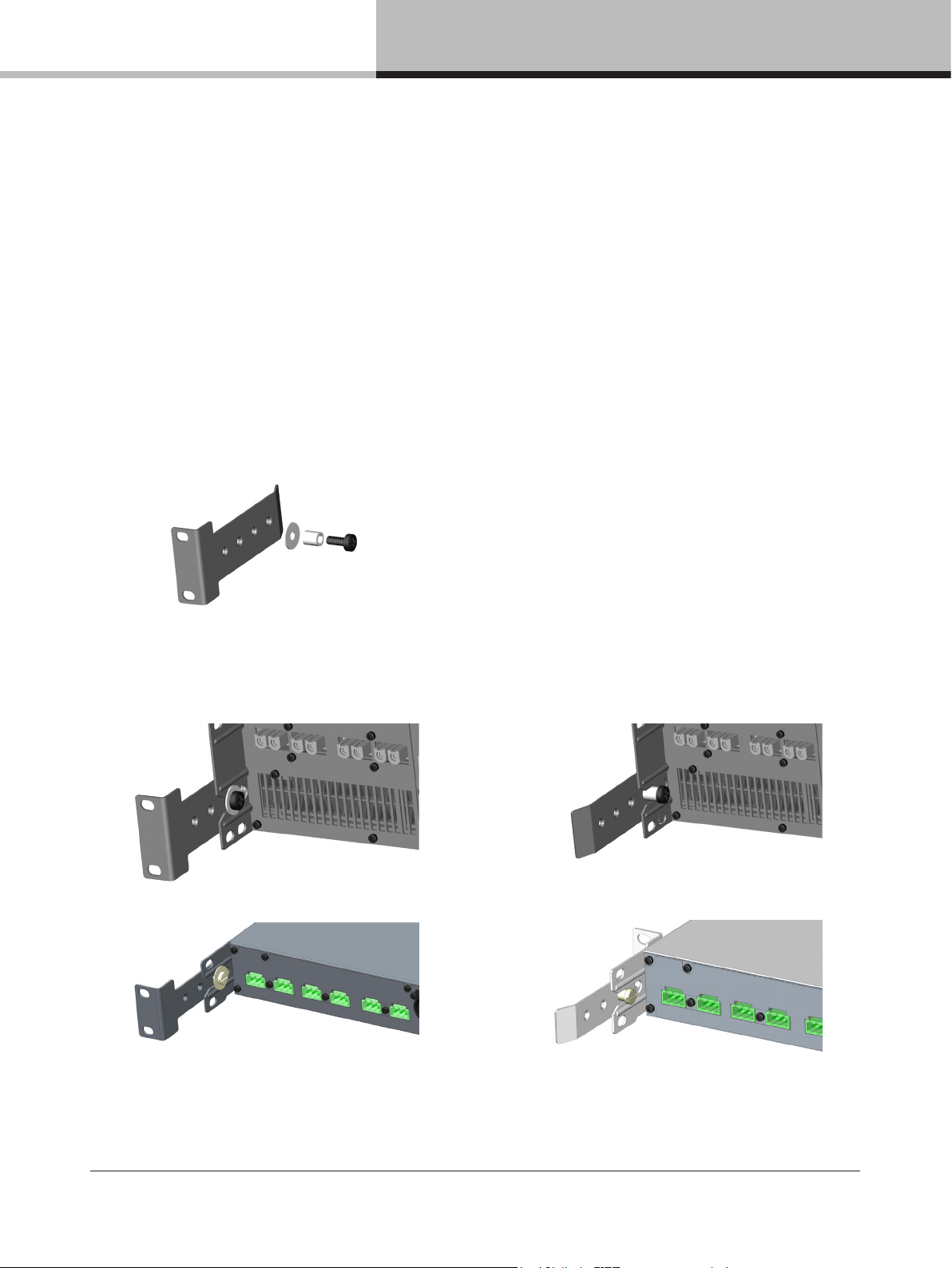
6.2.1. Rear Mounting
Two rear support brackets, along with associated mounting hardware, are included with the D Series device. It is
strongly recommended that these are used wherever possible. Fit the brackets to the vertical rails at the rear of the
rack. The following diagrams show the tting options for xed and removable installation. The support brackets are
reversible and may be tted to point either to the front or rear of the rack; the proper orientation depends on the
rack depth and position of the rear rack rails.
Figure 6.1: Rear support bracket with
mounting hardware
Figure 6.2: Rear support bracket mounted for Figure 6.3: Rear support bracket mounted for
xed installation and bracket removable installation and bracket
pointing forward pointing towards rear
D SERIES Lake Operation Manual rev 3.0.1
9
Page 10
6. Installation
6.2.2. Mounting front grille
The front grille is shipped on top of the amplier inside the box to protect it during shipping. The front grille adheres
to the amplier with magnets. Hold the front grille with your ngers in each of the side cutouts and slide it gently into
place straight from the front.
6.3. Cooling and fan operation
D Series devices use a forced–air cooling system with airow from front to rear, allowing high continuous power
levels without thermal problems. To facilitate maximum air ow, ensure that no objects such as rack doors or
lids are placed at the front or rear of the rack. Never attempt to reverse the airow. Make sure an adequate air
supply is provided in front of the D Series device, and that the rear of the device has sufcient space to allow
air to escape. It is recommended to keep the ambient temperature around the device as cool as possible. An
increased temperature can have a signicant negative impact on the expected lifetime on the components
inside the D Series device.
NOTE: Always ensure the dust lters behind the detachable front panel are clean to ensure maximum
possible airow. The exterior front panel is held in place by powerful magnets but is easy to detach by
using your ngers in the openings at the each side. To clean the foam lter, detach it from the exterior
front and gently use a vacuum cleaner or gently shake it. Remount with the opposite procedure. Never
operate the amplier without the dust lter installed.
NOTE: Fit solid blanks (not ventilation blanks) to unused rack spaces to ensure effective air circulation. Leaving
gaps in between items of equipment degrades the effectiveness of forced–air cooling.
If installing one or more D Series devices in a rack with other fan–cooled equipment, conrm that all other
equipment also uses front–to–rear airow for cooling. If this precaution is not observed, there is a risk of
overheating, as units with the reverse airow will be drawing in air which has already been heated by the
D Series devices.
The D Series device is equipped with a sophisticated temperature sensing system which protects it from any
overheating which may occur as a result of inadequate ventilation.
6.4. Operating voltage
D Series has a universal power supply and its mains nominal and operating voltages are specied in the Technical
Specications. D Series can be ordered with a variety of mains plugs. If the mains plug (AC plug) tted to the mains
cable (AC cord) is not appropriate for your country it can be removed and a locally–sourced one tted instead. If
you are not 100% condent of your competence to replace the mains plug (AC plug), the task should be carried
out by qualied personnel.
NOTE: In–rush current is controlled and limited during the soft–start sequence. This enables multiple D
Series Devices on the same AC mains circuit to be turned on simultaneously.
D SERIES Lake Operation Manual rev 3.0.1
10
Page 11
6. Installation
3 phase Y 120V
6.4.1. Low voltage country considerations
Although the D Series has a wide range of operating mains voltage, some considerations can be applicable for
low voltage regions. D Series performs well throughout the specied nominal voltage range but has slightly better
efciency at higher voltages. For regions with nominal voltage below 140 V, one could consider connecting the
amplier in a three phase delta or two phase split-phase conguration, especially applicable for the bigger models,
(D200, D120 and D80).
NOTE: Following connections applicable only for resulting voltage inside the ampliers nominal voltage
range.
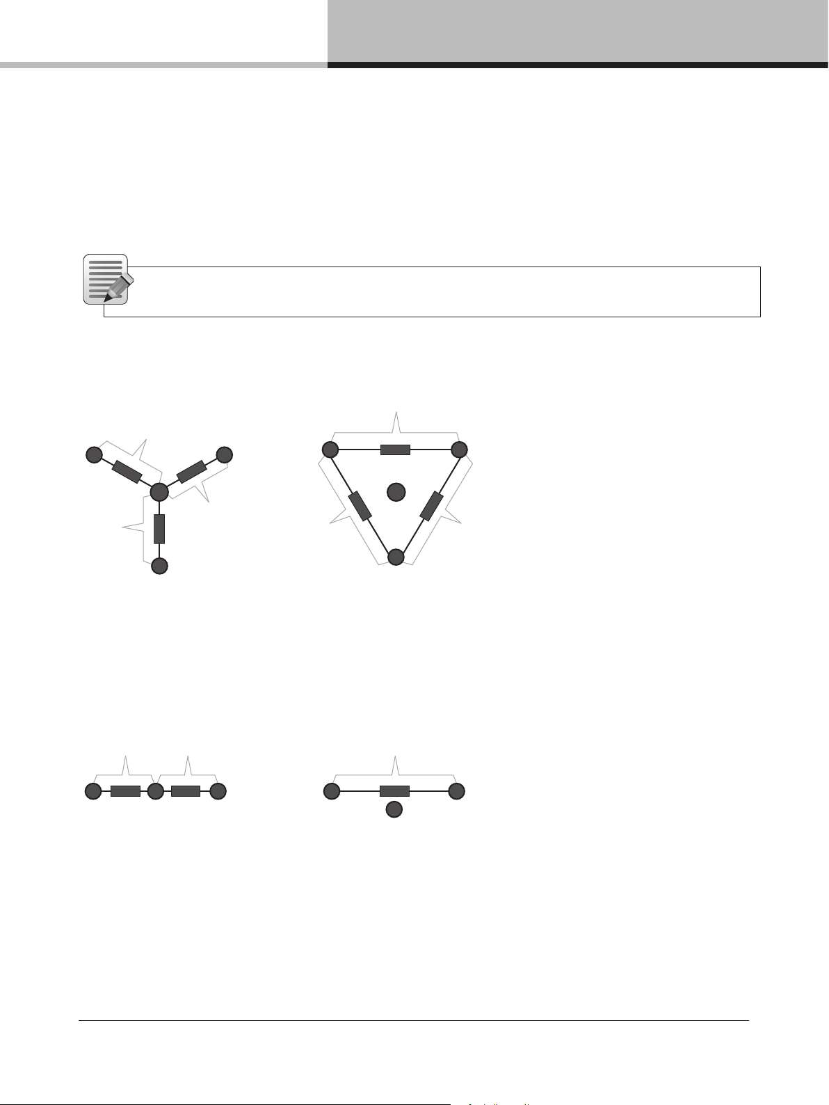
Connecting the amplier in three phase delta conguration
In three–phase conguration where the phases are 120 degrees apart, one can connect three balanced loads in a
delta conguration. The connection is made between the phases instead of between the neutral and a phase.
208V
120V
L1
Amp
L2
Amp
L1 L2
N N
Amp
120V
L3
120V
208V
Amp
Amp
Amp
208V
L3
3 phase delta 208V
Figure 6:4: Three phase delta conguration
Connecting the amplier in a split phase conguration
In two phase split–phase conguration there are two phases separated by 180 degrees. Connecting between the
phases gives double the line voltage.
100V 100V 200V
Amp
L1
Split phase 100V
Amp
L2N
L1 L2
Amp
N
Split phase 200V
Figure 6.5: Two phase split–phase conguration
6.5. Grounding
D Series must be grounded (earthed) with the safety ground pin to the mains distribution system. NEVER
disconnect the earth (ground) pin on the mains cable (AC power cord). Use correctly-shielded balanced audio
input connections to minimize hum and interference.
D SERIES Lake Operation Manual rev 3.0.1
11
Page 12
7. Product overview
7. Product overview
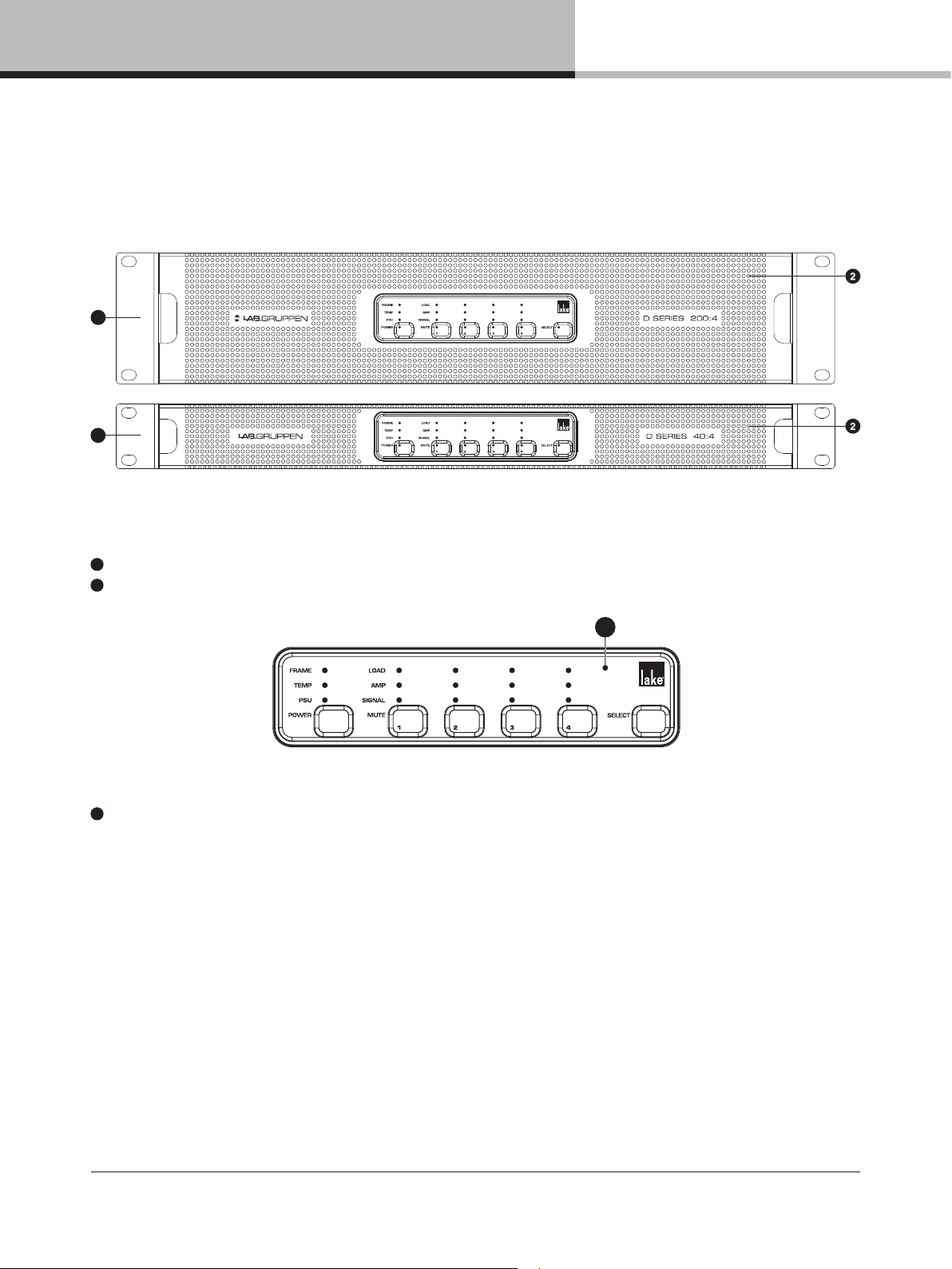
7.1. Front panel
1
1
The front panel consists of an outer front with air intake and a centered user interface. The user interface has LEDs
for monitoring and six recessed touch buttons for control.
1
Rack ears for 19 inch rack mount
2
Exterior front grille (also air intake and dust lter holder)
3
Touch and LED panel – See section 9.1 for further information.
3
D SERIES Lake Operation Manual rev 3.0.1
12
Page 13
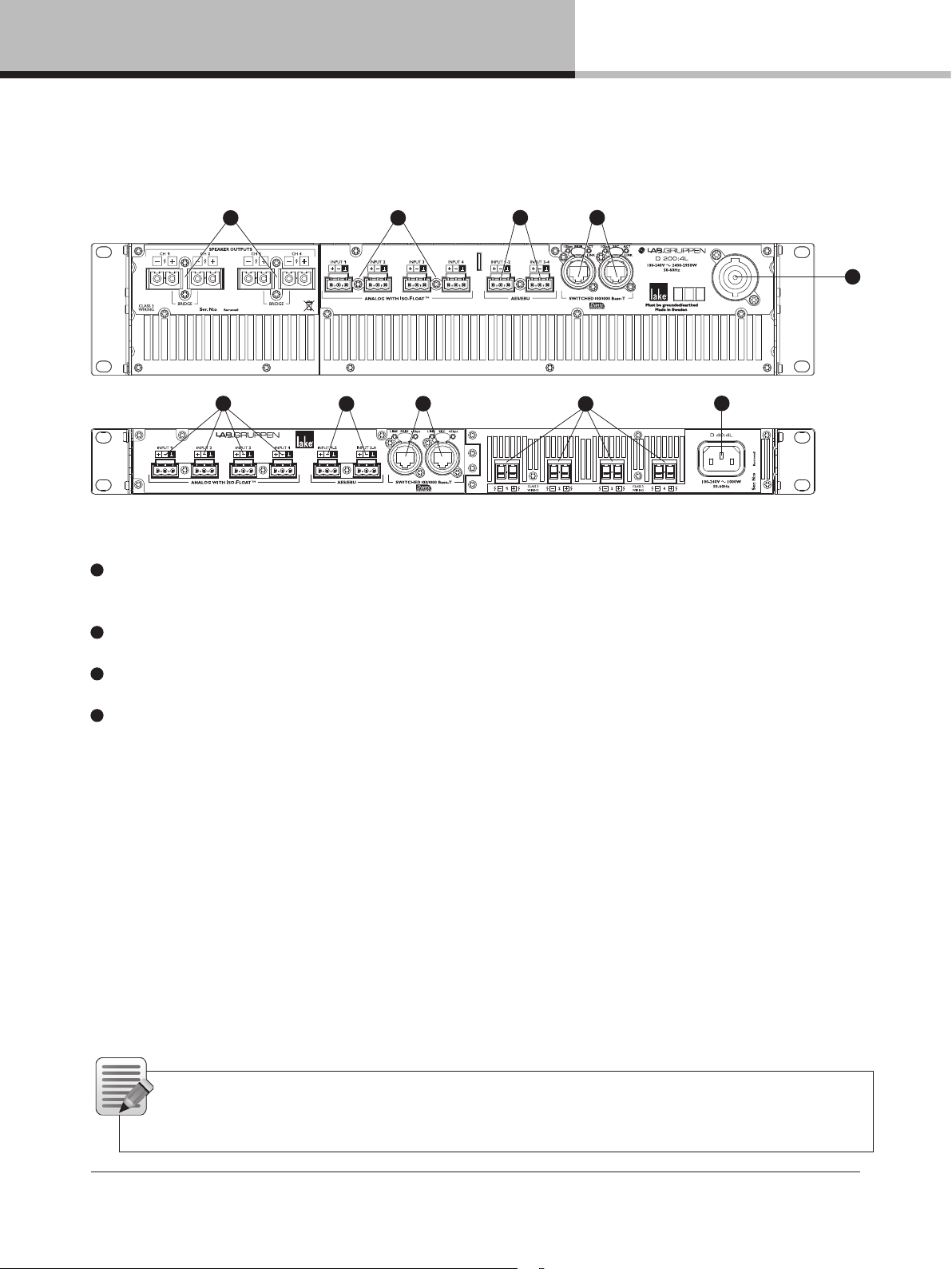
7.2. Rear panel
7. Product overview
1 2
2
1
3
4
3 4
1
5
marked hot (+) and cold (-) terminal
2
Analog Inputs - Analog inputs are available on terminal block connectors with clearly marked hot (+), cold (-)
and ground terminals
5
3
AES3 Inputs - AES3 inputs are available on terminal block connectors with clearly marked hot (+), cold (-)
and ground terminals
4
RJ-45 Ethernet connectors for control and Dante digital audio network
5
Mains connector - Detachable Neutrik powerCON (for D 200, D 120 and D 80) or locking IEC connector
D SERIES Lake Operation Manual rev 3.0.1
13
Page 14

7. Product overview
8. Signal flow, routing and mute points
8.1. Signal flow
device provides seven points in the signal chain where the signal level can be adjusted, muted or disconnected.
Module Data stored in Module FIles (Speaker Presets)
Frame Data stored in System Files and Frame Presets
Dante Receivers 1-8
AES/Analog
pass through
to Dante
INPUTS
AES 1-4
Analog 1-4
OUTPUTS
Dante 1-8
(no mutes)
Input
Routers
1-4
WITH
INPUT
MUTES
Input
Mixer A
Input
Mixer B
Input
Mixer C
Input
Mixer D
Lake Contour
Module A
Lake Contour
Module B
Lake Contour
Module C*
Lake Contour
Module D*
Attenuator
Phase Rev
Custom RPM
Attenuator
Phase Rev
Custom RPM
Attenuator
Output Routing
Phase Rev
Custom RPM
Attenuator
Phase Rev
Custom RPM
Mute
Mute
Mute
Mute
ISVPL
Auto RPM
ISVPL
Auto RPM
ISVPL
Auto RPM
ISVPL
Auto RPM
Amp Gain LoadSmart LoadPilot AMP
Amp Gain LoadSmart LoadPilot AMP
Amp Gain LoadSmart LoadPilot AMP
Amp Gain LoadSmart LoadPilot AMP
1 2 43 5
Figure 8.1: D Series Lake Signal Flow Diagram
1
The input section (inputs, input router and input mixer) allows for mixing capabilities as well as redundant and
prioritized inputs with automatic switch-over in case of signal failure
2
Up to four Lake Processing modules provide user EQ and loudspeaker processing, including LimiterMax limiting
3
The Output router allows free routing between module outputs and power output channels
4
Each power output channel provides individual channel processing, including ISVPL limiter, RPM and
load monitoring
5
8.2. Level Adjustments & Mute Points
the signal:
1 Input Router Stage Input selection and MUTE
2 Input Mixer Stage Router on /off connection to mixer and gain settings
3 Module Input Stage Mute and gain settings
4 Module Output Stage Mute and gain settings
5 Output Router Stage Output on /off routing connections
6 Attenuation Stage Power output channel mute and attenuation settings
7 Amp Gain Stage
NOTE: If the required audio signal is not passing correctly, verify the connection, mute and gain settings
at all seven stages.
D SERIES Lake Operation Manual rev 3.0.1
14
Page 15
9. Front panel interface
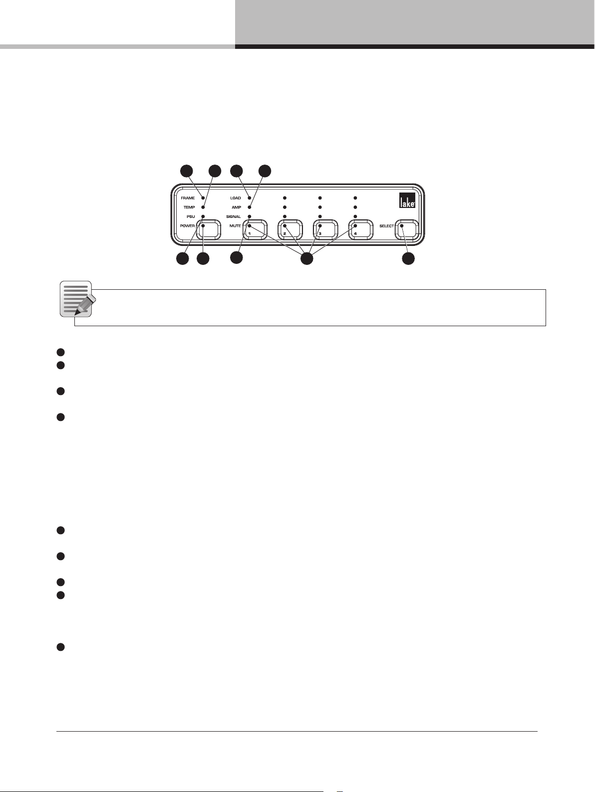
9.1. Frame status and control
1 2 5 6
9. Front panel interface
43
7
8
9
NOTE: General status indication shown in Table 9.1. For detailed information on warning and fault
indication, please refer to the Faults and Warnings table in Section 14.1.
1
FRAME LED – Provides status indication for a number functions affecting the amplier frame
2
TEMP LED – Provides status indication for internal temperatures sensed at multiple points, including power
supply, DSP and output channels
3
PSU LED – Provides status indication on functionality of Power Supply Unit and mains supply, including under–
and over–voltage, power supply faults, and unstable mains supply
4
POWER LED and TOUCH BUTTON – Provides power state indication and control. Press and hold button to
toggle the amplier between ON and STANDBY state. LED indication given in Table 9.1.
9.2. Channel status and control
5
LOAD LED – Provides load related status indication for monitoring functionality of LoadSmart and LoadPilot.
Warnings and faults indicate problems or anomalies detected in the connected loudspeakers and/or cabling
6
AMP LED – Provides amplier related status indication, including faults and warnings related to temperature,
over–current, clipping and very high frequency
7
SIGNAL LED – Provides signal related status indication, including no signal and input signal clipping
8
MUTE LED and TOUCH BUTTON – Provides mute status indication and control. The LED is indicating
both Lake mutes and power channel mute. A single touch on the mute button toggles the power channel mute
between mute and unmuted states
9
SELECT LED and TOUCH BUTTON – for selection and indication control between computer software and unit
D SERIES Lake Operation Manual rev 3.0.1
15
Page 16
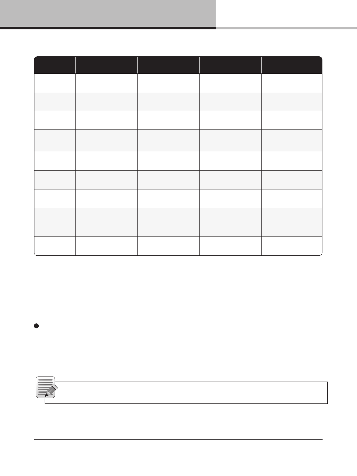
9. Front panel interface
OFF Green Amber Red
Frame
N/A Frame OK Frame warning Frame fault
Temp
N/A Temp OK Temp warning Temp fault
PSU
N/A PSU O K
Power supply/
Mains warning
Power supply/
Mains fault
Power
No mains power
Fixed:ON
Blinking: Turning ON
Button pressed.
Hold for transition
Fixed: STANDBY
Blinking: Turning to
STANDBY
Load
No LoadPilot active
LoadPilot active
and LoadOK
Load warning Load fault
Amp
N/A Power channel OK Power channel warning Power channel fault
Signal
Output below signal
present threshold (– 60 dB)
Output above signal
present threshold (–60 dB) input clip (–2 dB) or limit/ fault active
Mute
Inactive channel in
bridge operation
Unmuted
Lake module is muting the
signal chain at either input
router, module input or
module output
Power channel muted
Select
Frame not selected Frame selected Waiting for more touches N/A
Input signal approaching Input signal clip
Table 9.1: LED/category chart
9.3. Frame select and ID
9
SELECT LED and TOUCH BUTTON – Selects mode and indicates control between computer software and
unit. A single touch on the button will select the unit in supported computer software views. Multiple consecutive
touches will select the corresponding Lake module (one touch for module A, 2 for module B etc.). In the other
direction, when selecting the unit in a supported computer software view, the LED will indicate the unit is selected
with steady green illumination.
16
NOTE: The touch buttons use capacitive touch technology and might be sensitive to large temperature
and humidity variations.
D SERIES Lake Operation Manual rev 3.0.1
Page 17

9. Front panel interface
9.4. Additional front panel operations and indications
9.4.1. Frame reset
A factory reset and soft reset can be performed from the front panel. A factory reset will restore all settings to
original defaults, including network settings, frame presets and current settings. A soft reset reverts only the current
settings to default. Network settings and frame presets are not changed with a soft reset.
6. Place the frame in standby mode.
7. Press and hold Select and channel 3 mute button. Then press the power button.
8. User interface will illuminate available options. Choose from the options below
a. Press channel 1 mute button (red LED) to initiate the factory reset sequence.
b. Press channel 2 mute button (amber LED) to initiate the soft reset sequence.
c. To cancel, press channel 4 mute button (green LED).
9. Wait state indication is present while either reset is performed.
10. To complete the factory reset process, cycle the mains power by completely removing the power plug and
reinserting it.
9.4.2. Wait indication
Wait indication is displayed when the frame is performing an operation. All LEDs except power are unlit and a
circling amber light is displayed on channels 1 and 2.
9.4.3. Power cycle required indication
After an operation that requires a subsequent power cycle to complete, the power LED blinks alternately red and
green. A Power cycle requires that the mains is completely removed from the device and not connected again
until the device has powered off.
9.4.4. Front panel lock
The front panel can be disabled from the Lake Controller. When the front panel is disabled, LEDs 4, 8 and 9
(all buttons on the lowest row) flash in amber when hitting any touch button.
D SERIES Lake Operation Manual rev 3.0.1
17
Page 18
10. Rear panel interface
10. Rear panel interface
1 2
2
3
4
3 4
1
5
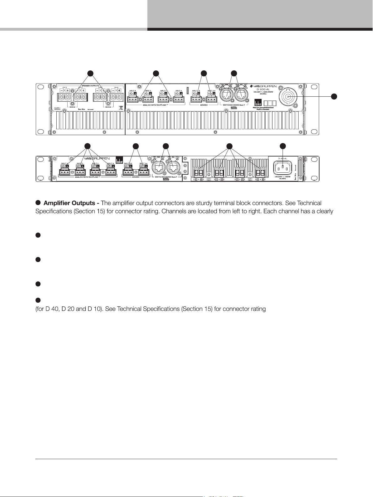
For electrical specications on inputs and outputs, please refer to Technical Specications in Section 15.
1
Amplier Outputs – The amplier outputs utilize mating Phoenix–type connectors. Connect loudspeaker
cables to the mating plug–in connectors observing polarity (including bridge mode option for D200, D120
and D80) as marked on the rear panel
2
Analog Inputs – Analog inputs are available on terminal block connectors with clearly marked hot (+), cold (–)
and ground terminals. The inputs are electronically balanced and feature Lake Iso–Float circuitry
3
AES3 Inputs – AES3 inputs are available on terminal block connectors with clearly marked hot (+), cold (–) and
ground terminals
4
RJ–45 Ethernet connectors for control and Dante digital audio network. Neutrik etherCON connectors
accept either mating etherCON connector or a standard RJ–45 connector.
5
Primary Network Connector – The primary connection provides integration into an Ethernet control network
which may include other Lake Processors and the Lake Controller software. Network connection permits full
control of all functions along with real–time metering from a remote position.
This device supports the Dante audio networking protocol, which allows transmission of multichannel, high–
denition digital audio over the same Ethernet connection.
Use the primary connector when using a star network topology, consisting of individual Cat–5e connections
between the devices and an Ethernet switch. Alternatively this connection can be used to daisy chain directly
to another Lake Processor. The daisy chain topology should not be used with Dante.
Additional information is also available in the Lake Network Conguration Guide.
NOTE: The Ethernet ports operate at the Ethernet data rate of up to 1 Gbps and allow straight or
crossed network cables. LEDs above each port indicate network activity (ACT) and Gigabit network
connections (Gbps). If Gbps LED is unlit, speed is 100 Mbps.
D SERIES Lake Operation Manual rev 3.0.1
18
Page 19

11. Operation and performance
Secondary Connector – The secondary network connector can be used to create a Dante dual–network
topology by connecting all secondary network connectors to a separate Ethernet switch, ensuring full
redundancy in the event of a network component failure. Alternatively, the secondary network connector can be
used to daisy–chain multiple Lake devices (LM, PLM, PLM+ or D Series), if Dual Redundancy is Disabled from
the Lake Controller. When the device is in Dual Redundancy , it is possible to connect a Lake Controller to the
Secondary Connector as long as the IP address on the computer is on the 172.31.x.x subnet.
ed via Lake Controller. See the Lake Controller Operation Manual for further details.
NOTE: When connecting multiple devices to an Ethernet network, care must be taken NOT to create a
closed loop which causes network malfunction.
5
Mains connector – Detachable Neutrik powerCON (for D 200/120/80) or locking IEC connector (D 40/20/10).
For more information, please refer to Section 6.4.
11. Operation and performance
11.1. Operation precautions
Make sure that the Standby button on the unit’s front panel is either unlit (OFF), or red (STANDBY), before making
any input or output connections. Ensure the AC voltage is within the range printed on the label adjacent to the AC
mains connector. Ensure no input signal is present when powering on the unit to reduce the risk of any inadvertent
bursts of high level audio.
11.2. Power output performance
The standard form factor D Series units (D200, D120 and D80) uses Lab.gruppen’s patented Class TD
purity of Class A/B designs. The slimline D Series units (D40, D20 and D10) uses a newly developed Class D:
perfectly under all load conditions and the output maintains it
with very low nominal impedances. Reliability is very high, and there is no interference with nearby RF equipment.
D SERIES Lake Operation Manual rev 3.0.1
19
Page 20
11. Operation and performance
Load Impedance (ohms)
2 ohms
(per channel)
2.67 ohms
(per channel)
4 ohms
(per channel)
8 ohms
(per channel)
16 ohms
(per channel)
Hi-Z 70 V
(per channel)
Hi-Z 100 V
(per channel)
D 200:4L 4400 W 5000 W 4400 W 23 00 W 1150 W 3300 W 4700 W
D 120:4L 3000 W 3000 W 3000 W 1900 W 950 W 3000 W 3000 W
D 80:4L 2000 W 2000 W 2000 W 1500 W 750 W 2000 W 2000 W
D 40:4L 800 W 1000 W 1000 W 1000 W 700 W 1000 W 1000 W
D 20:4L 500 W 500 W 500 W 500 W 425 W 500 W 250 W
D 10:4L 250 W 250 W 250 W 250 W 250 W 250 W 175 W
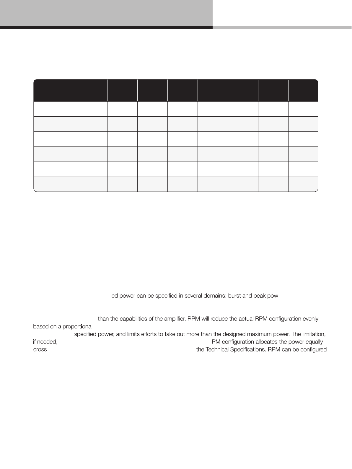
11.2.1. Symmetrical power
D Series models can deliver power as shown in Table 11.1 when all channels are driven equally.
Table 11.1: Symmetrical Load Power Ratings
11.2.2. Rational Power Management™
Rational Power Management™ (RPM) is a unique Lab.gruppen feature that allows for exible allocation of power
across channels of a D Series unit. Power that is not used by one output channel is free for use by another output
channel with greater demands. Unique to this series is that all models in the range have amplier channels that can
produce higher outputs than the average 25% of the total power, see the Technical Specications for the maximum
single channel power capacity. RPM automatically allocates power up to the total limits of the specic amplier
model and helps minimize unused power in the installation.
RMS voltage; and also the speaker’s AES power rating. By specifying the nominal impedance of the load, the RPM
algorithms have all input data required to calculate resulting RPM settings. If the desired RPM settings results in a
total power output higher
of delivering the
is performed with the ISVPL limiter algorithm. As default the R
the channels at a voltage (default voltage limitation) given in
in two modes.
er; peak and Via the CAFÉ Software, desired
reduction in dB. Once applied, the RPM functionality will ensure that all channels are capable
D SERIES Lake Operation Manual rev 3.0.1
20
Page 21
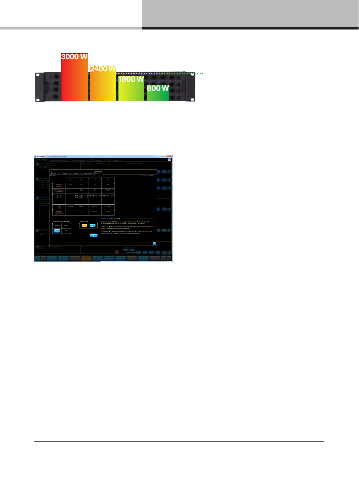
2000 W
11. Operation and performance
LOW
Figure 11.2: Amp channels power adjusted to match the loudspeaker requirements on a D 80:4
Auto RPM: The frame will automatically allocate power per output channel according to the ISVPL settings in the
speaker preset (per module output) in Lake Controller. Auto RPM assumes a nominal impedance of the Load and
applies an approximate power allocation. Auto RPM is default for D Series Lake.
MIDSUB
HIGH
Custom RPM: The CAFÉ software allows users to create an advanced custom power allocation scheme.
Switching to Custom mode disables the Automatic mode. Additional information is available in documentation
supplied with the CAFÉ software download.
Custom RPM using CAFÈ with ESP: CAFÉ (Conguring Ampliers For the Environment) is a dedicated software
application for Windows and OSX that provides tools for system planning, specication and commissioning. CAFÉ
incorporates the Equipment Specication Predictor (ESP), a software module that examines SPL and speaker
requirements for a project and generates requirements for output power on an amplier and system level. ESP will
generate a custom RPM conguration optimizing the power allocation within the frame. For more information on
CAFÉ and ESP, please consult the documentation supplied with the CAFÉ software download.
11.3. Amplifier and Load Protection Systems
The D Series is equipped with a comprehensive set of protection circuits. If operating conditions become
sufciently extreme that any of these circuits become active, indication is provided by amber or red LEDs on the
front panel, and by text notications in the Lake Controller and CAFÉ software. Refer to Section 14.1 for more
information on warnings and faults.
D SERIES Lake Operation Manual rev 3.0.1
21
Page 22

11. Operation and performance
11.3.1. Inter–Sample Voltage Peak Limiter (ISVPL)
The ISVPL is a high quality voltage limiter that can deliver seamless limitation to any desired level. It ensures that
the voltage at the output terminals never exceeds the dened threshold. It operates on these principles:
• The signal is delayed slightly to allow the ISVPL to look–ahead and reduce the gain before voltage in excess
of the threshold can appear at the output. This results in zero voltage overshoot at the output with a rounded
limitation up to the threshold.
• The amplitude of the output signal between digital samples is predicted which permits the ISVPL to respond to
analog peaks that may occur at the digital to analog converter.
• The release time of gain reduction is adaptive depending on the dynamics of the signal. It is possible to select
different ISVPL proles for limiting optimization for a specic frequency band and personal preference. The
proles are divided into two categories, with one category optimized for low distortion and the other focusing
on producing high sound pressure level (SPL). Within each category there are proles optimized for the different
frequency bands.
11.3.1.1. Low Distortion Profiles
• Universal – The universal prole is a soft limiter that can be used for all frequencies and is conservative in its
action upon VCL and CPL.
• Sub/LF – The Sub/LF prole is tuned for frequency bands below 600 Hz. It has longer attack and release times
and is less conservative when it comes to acting upon VCL and CPL.
11.3.1.2. High SPL Profiles
High SPL proles do not use the adaptive release time feature. High SPL proles optimized for high frequencies
use less of the look–ahead delay peak–rounding feature; this feature is used most in the Sub prole and least the
HF prole.
• Sub – The Sub prole is optimized for frequencies between 20 – 200 Hz
• LF – The LF prole is optimized for frequencies between 20 – 1200 Hz
• MF – The MF prole is optimized for frequencies between 300 – 6000 Hz
• HF – The HF prole is optimized for frequencies above 1 kHz
11.3.1.3. ISVPL Voltage Settings
The ISVPL threshold may be set at any level between 17.8 V and 600 V in the Lake Controller software. For further
details, please refer to the Lake Controller User Manual.
Lake–enabled amplier devices (D Series Lake, PLM+, PLM) that have a smaller peak output voltage capability still
allow ISVPL speaker threshold settings up to 600 V. When a threshold is set above the current maximum capability
of a power output channel, the actual ISVPL will automatically be set to the maximum ISVPL for that channel.
Therefore, the ISVPL threshold can be set at the Module for the speaker’s maximum capability, and the Module le
remains cross–compatible with all Lake–enabled amplier devices.
Table 11.3 shows the theoretical maximum output power based on only the load impedance and
the ISVPL setting. See the Technical Specications, or use CAFÉ, to nd the available power for a specic
amplier and load.
D SERIES Lake Operation Manual rev 3.0.1
22
Page 23

Max. Sinewave Burst Power (Watts)
LLoad Impedance (ohms)
2 2.67 4 8 16
LISVPL SETTING (V peak)
194 4489 5993 470 5 2352 1176
193 4489 5993 4656 2328 116 4
181 4489 5993 4095 2048 10 24
167 4489 5223 3486 1743 872
153 4489 4384 2926 1463 732
121 3660 2 742 1830 915 458
101 2550 1910 12 75 638 319
83 172 2 12 90 861 431 215
70 122 5 918 613 306 153
56 784 587 392 196 98
47 552 414 276 13 8 69
38 361 270 181 90 45
17.8 79 59 40 20 10
Table 11.3: ISVPL–to–output examples
11. Operation and performance
11.3.2. Current Peak Limiter (CPL)
The output Current Peak Limiter (CPL) ensures that the power output section will not be damaged by forcing it to
deliver current levels at the outputs that exceed the maximum current ratings of the output transistors. The CPL
keeps the output transistors within their Safe Operating Area (SOA). The CPL is non–adjustable.
This condition indicates an attempt to draw excessive current at the output. The output is attenuated until the
output current falls below the maximum current rating. Limiting is performed by the ISVPL limiter in conjunction
with the selected ISVPL prole.
CPL activity is shown by amber or red indication on Amp LED of the affected output channel and a corresponding
text description in Lake Controller and CAFÉ software programs. Refer to Section 14.1 for more information on
warnings and faults.
NOTE: If excessive current is indicated, check the output cables and examine the loudspeaker. If
impedance appears normal, you may rectify the condition by altering the ISVPL settings or lowering
input levels. CPL indication can be triggered by excessively low load impedance, possibly the result of
too many loudspeaker cabinets connected in parallel.
11.3.3. Power Average Limiter (PAL)
The Power Average Limiter Active warning (PAL Active) will be displayed when the power supply is operating at the
maximum average input power allowed for the PSU design. When this warning is displayed, gain limiting is being
applied to the signal by a lowering of the ISVPL threshold.
D SERIES Lake Operation Manual rev 3.0.1
23
Page 24
11. Operation and performance
PAL activity is shown by PSU amber LED indication and a corresponding text description in Lake Controller and
CAFÉ software programs. Refer to Section 14.1 for more information on warnings and faults.
11.3.4. Breaker Emulation Limiter (BEL™)
The BEL models the temperature in the external breaker and limits the mains current to prevent the breaker
be selected for Frame Replace support). The desired nominal current value can be set from 1 to 32 Arms. The
resulting
models
the
•
•
allows current above the threshold to pass for a short time, leading to an increased modeled temperature. For
the limiter to disengage, the current must reduce below the threshold to enable the breaker to cool down.
•
momentarily allows current above the threshold for a longer time, leading to an increased modeled temperature.
ed current for the breaker to cool down.
is set above, or bellow, the model’s capabilities, the actual current is automatically adjusted into
:
predict the current consumption, with the exact speaker requirements, and propose a safeguarding
11.3.5. Under Voltage Limiter (UVL™)
The larger D Series devices (not D 20:4L and D 10:4L) are equipped with an under voltage limiter. With multiple,
powerful devices on a mains distribution line, heavy current loads risk the reduction of voltage below that
required for devices to function. The UVL reduces the mains current draw when voltage drops below 80 V.
The amount of reduction applied increases as mains voltage drops towards 65 V; at 65 V the power supply is
automatically restarts.
11.3.6. Current Average Limiter (CAL™)
The Current Average Limiter (CAL) monitors the RMS current drawn from each power output channel to ensure
that the power output stages are not overloaded. When activated, it regulates the current to a safe level to
protect the channel. The CAL should not be activated in normal usage. If activated, this is shown by amber or red
indication on the Amp LE
and CAFÉ software programs. Refer to Section 14.1 for more information on warnings and faults
D of the affected output channel and a corresponding text description in Lake Controller
D SERIES Lake Operation Manual rev 3.0.1
24
Page 25
11. Operation and performance
NOTE: For Slimeline models, to optimize the CAL’s behavior when playing into a low
impedance load, manually set the desired ISVPL to reflect the real peak voltage
output to allow for a higher average current.
11.3.7. Voltage Clip Limiter (VCL)
If current draw from the unit’s power supply is too high, the PSU’s regulation capability may be exceeded and
the internal voltage rails may drop and cause clipping. If this occurs, the VCL acts rapidly to prevent clipping on
the subsequent peaks. Limiting is performed by the ISVPL limite
Indication of this condition is shown on the output LEDs. Refer to Section 14.1 for more information on warnings
and faults.
11.3.8. Temperature Protection
D Series devices are equipped with a sophisticated temperature sensing system that provides protection
from overheating which may occur as a result of inadequate ventilation or excessive power output. Thermal
measurements are made at several points within each power output channel along with measurements in
operate continuously, with the highest possible output, and prevent shutting down. If temperature in any area
reaches a critical level, a warning is displayed. The warning is issued at approximately 80% of the maximum
allowable temperature. If the temperature continues to increase, a limiter (ATL or PTL) is engaged that limits signal
peaks to reduce further heat accumulation. Limiting is accomplished by gradual reduction of the ISVPL thresholds.
In the extreme case where the limiter cannot reduce heat accumulation and temperature reaches a
dangerous level, a fault is displayed and audio is muted.
Each power output channel, the power supply, and DSP area have separate indications. For all temperature faults,
temperature monitoring will continue at 0.5 second intervals, with the output remaining muted. When the area has
cooled below the dangerous threshold, the fault condition is cleared and audio is restored.
11.3.8.1. Power Output Channels
A power output channel temperature warning or fault is indicated by the Amp LED for that channel and the Temp
LED for the frame.
• A warning is indicated by a static amber LED
•
• A fault is indicated with a static red LED
An event report is sent to the Lake Controller software for both the warning and the fault. If a temperature fault
condition arises on a power channel, the output of that channel will be muted.
D SERIES Lake Operation Manual rev 3.0.1
25
Page 26
11. Operation and performance
If the amplier output channel temperature keeps rising after reaching the temperature warning threshold, the Amp
channel Temperature Limiter (ATL) will engage at approximately 95% of the maximum allowable temperature.
When ATL is engaged, it will try to reduce the power output to avoid that the amp channel goes into temp fault,
i.e. muting. Limiting is removed when temperature falls below the ATL threshold.
11.3.8.2. Power Supply / DSP
A power supply (PSU) or DSP temperature warning or fault is indicated by the Temp LED.
• A warning is indicated by static amber LEDs
• Power supply Temperature Limit (PTL) is indicated by an amber LED
• A fault is indicated with static red LEDs
If the power supply temperature keeps rising after reaching the temperature warning threshold, the Power supply
Temperature Limiter (PTL) will engage at approximately 95% of the maximum allowable temperature. When PTL
is engaged, it will try to reduce the total amplier output power to avoid that the power supply goes into temp fault,
i.e. muting of all channels. Limiting is removed when the temperature falls below the PTL threshold.
11.3.9. DC Protection
The DC protection is implemented, individually, on each power output to prevent damage to connected
loudspeakers or any D Series components. DC present at the output will cause the unit’s power output module
breaker to blow, causing a permanent hardware fault that prevents signal throughput. In this instance the channel’s
Amp LED will illuminate red and a service channel fault will be registered in the Lake Controller and CAFÉ status
views (D200, D120, D80 only). For the D40, D20 and D10, no audio will be heard from the outputs.
NOTE: A blown breaker in the power output module is not a user serviceable fault condition and the
unit should be returned for repair.
11.3.10. VHF Protection
The D Series includes protection circuits that detect Very High Frequency (VHF) content in the input signal. The
detection is amplitude–, frequency– and time–dependent. It is initiated from 10 kHz upwards and, if continuous
VHF signals are detected above the threshold for more than the attack time, the output for a D200, D120 and
D80 will attenuate the gain until the signal is below the VHF threshold. When this is done, VHF Warning is
displayed. If the signal is above the VHF threshold and the maximum of -12 dB of gain reduction is not enough
to take the signal below the VHF threshold, the signal will mute after 15 seconds, and retest the signal after
6 seconds. Note that the D40, D20 and D10 will go directly to mute upon VHF detection.
normal operation.
This protection system recognizes only continuous VHF signals at high levels that will not appear in speech or
music. Any such content can therefore be considered as a fault condition. VHF protection is essential to avoid
damage to HF drivers. VHF protection is dependent on a combination of output power level and frequency.
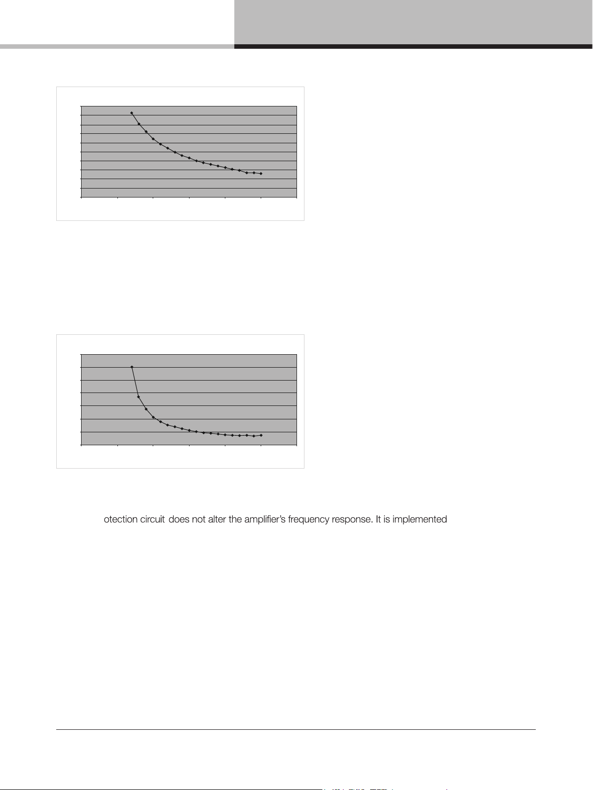
Figure 11.4 shows a decreasing power threshold, from approximately 10 kHz upwards, which illustrates increasing
sensitivity of the protection system with frequency. When continuous output power above the threshold line is
detected, VHF protection becomes active.
D SERIES Lake Operation Manual rev 3.0.1
26
Page 27
11. Operation and performance
Trigger voltage
100
90
80
70
60
50
40
30
Voltage [Vrms]
20
10
0
0 5
Fig 11.4: VHF Protection Frequency Sensitivity
The attack time of the VHF protection circuitry also changes with frequency, becoming shorter at higher
frequencies. This is shown in Figure 11.5.
10 15 20 25 30
Frequency [kHz]
Full output voltage
1400
1200
1000
800
600
Time [ms]
400
20
200
0
0 5
10 15 20 25 30
Frequency [kHz]
Fig 11.5: VHF Protection Attack Time Variations
The VHF pr
solely to detect
continuous VHF content. HF content of normal music or speech signals at peak levels will be passed in full.
Operation of the VHF protection circuits is indicated by the channel’s AMP LED that will illuminate yellow and
display VHF Warning when the max of -12 dB of gain reduction is applied (only applicable for D200, D120
and D80) and light red for a VHF FAULT. Both of these will be registered in the Lake Controller and CAFÉ
status views.
11.3.11. Short Circuit Protection
A low impedance or short circuit at the power output terminals is detected when the output current is high (Current
Peak Limiter is active) and, simultaneously, the peak output voltage is below a predetermined threshold. When this
situation occurs, the output stage is muted to protect it from damage.
Operation of the short circuit protection system is indicated by Amp channel LED showing steady red and a
corresponding text description will register in Lake Controller and CAFÉ software programs. Refer to Section 14.1
for more information on warnings and faults.
D SERIES Lake Operation Manual rev 3.0.1
27
Page 28
11. Operation and performance
The presence of a short circuit (or low impedance) is re–tested every six seconds, and the output remains muted
until the fault clears.
11.3.12. Power supply protection
The power supply is very advanced and has several internal control and monitoring functions. Should any of these
fail, the power supply will shut down to prevent damage or limit severity of the failure. If the power supply shuts
down audio will be muted. Power supply faults, or power supply needs service faults, are indicated by a red LED
and associated error messages registered in Lake Controller and CAFÉ software programs.
In the extreme event of simultaneous low mains voltage supply and high power demand, the amount of incoming
condition is a power protect fault, indicated with a red LED and associated error messages registered in Lake
Controller and CAFÉ software programs.
11.3.12.1. Mains anomaly protection
supply will then be forced to shut down. This
mains service.
Over–voltage – If the power supply detects mains voltage above 400 V peak or 270 V RMS, it will enter protective
associated error messages will register in Lake Controller and CAFÉ software programs.
Under–voltage – If the power supply detects mains voltage of less than 65 V (not available on D10 and D20),
it will enter protective shut down mode. The amplifier will auto–restart if the condition clears. Will be indicated
by a red LED and associated error messages will register in Lake Controller and CAFÉ software programs.
Mains instability – If the power supply detects protracted instability in the AC mains, it will enter protective
shut down mode (D 200:4L, D 120:4L and D 80:4L only). The ampli
Will be indicated by a red LED and associated error messages will register in Lake Controller and CAFÉ
software programs.
Mains glitch – If the power supply detects a momentary mains glitch (missing cycles) at the AC inlet, a warning
indication will be reported with a yellow LED and associated error messages will register in Lake Controller and
CAFÉ software programs (D 200:4L, D 120:4L and D 80:4L only). The powers supply and product continue
operation throughout a mains glitch.
11.4. Power Supply
The R.SMPS (Regulated Switch Mode Power Supply) is designed to keep supply voltage rails at optimum levels.
Thus the R.SMPS can deliver full rail voltage to the output sta
consistent transient response and a clean LF response.
D SERIES Lake Operation Manual rev 3.0.1
28
Page 29
11. Operation and performance
D Series features a universal power supply with power factor correction (PFC). The device can accept any mains
voltage, from 65 V to 265 V, allowing it to function worldwide in many different congurations. The PFC reduces
current peaks on the lines and reduces the requirements placed on the mains distribution system. D Series units
offer an unparalleled power factor extremely close to one.
11.4.1. Low Inrush Current
High power ampliers with inadequate inrush current limiting can draw considerable current from the mains at
turn–on, sometimes tripping a fast–acting mains breaker. The D Series, however, has very low inrush current to
prevent tripping of breakers. Several units can, under normal conditions, be powered up simultaneously. If you
do experience problems powering up multiple units simultaneously, they must either be turned on manually in an
ordered manner, or sequenced remotely using the Lake Controller software’s Global Control feature. Alternatively,
the capacity of the mains supply should be increased.
NOTE: If insufcient power is available to allow simultaneous power–up, then there is probably
insufcient capacity for full power output during operation. It is recommended that additional capacity is
added to the mains power distribution system.
11.4.2. Adaptive rail control
The D Series slimline models have Adaptive rail control available in Performance (default) and Green mode.
In Green mode, this feature further increase the slimline models green credentials by lowering the idle
consumption. This is achieved by lowering power supply’s supply voltage, to the
raised,
to allow for full power outtake, as soon as the signal returns. This feature is user controlled via the
Lake Controller, where it can be turned on or off.
11.5. Auto power down
The D Series models have been equipped with a Auto Power Down function. If Auto Power Down is enabled,
user-defined
audio passing and there is no user interaction via the Lake Controller, CAFÉ or 3rd party controllers.
When the
the frame will turn on again.
NOTE: There is no Auto Power On feature on the return of signal, the device will need to be actively
turned on after entering the standby mode via the Auto Power Down feature. This can be done from
the network via the Lake Controller or the 3rd party protocol or via the front panel button.
D SERIES Lake Operation Manual rev 3.0.1
29
Page 30

11. Operation and performance
11.6. LoadPilot Load Monitoring
11.6.1. Introduction
LoadPilot is a feature in D Series ampliers that can continually monitor the integrity of loudspeakers and cables
connected to the outputs to ensure that they are functioning properly and free from major anomalies or faults.
By implementing LoadPilot, systems incorporating D Series ampliers can be certied in compliance with voice
evacuation standards such as EN54–16 and NFPA72.
LoadPilot functions by automatically superimposing low–level pilot tones on the input signal (if any present) to the
amplier. One tone is below the range of human hearing (approximately 10–20 Hz) and the other above (24 kHz),
so the activity of LoadPilot is inaudible regardless of whether the system is currently reproducing program content.
High–resolution current sensing on the outputs can calculate the impedance of the load at the frequency of the
tones. Hence a stable measurement of the impedance of the load can be obtained and potential anomalies or
faults can be detected that would indicate impaired loudspeaker function or total inoperability due to failure of the
loudspeaker or faults in connected wiring. The superimposition of pilot tones and analysis is interleaved across the
amplier’s output channels with a maximum total cycle time of around 20 seconds.
LoadPilot is implemented and congured in the CAFÉ software. Monitoring status and fault indication are displayed
on the front panel and both in CAFÉ and Lake Controller.
LoadPilot may be congured with the automatic calibration or through a manual advanced mode, depending on
monitoring requirements and characteristics of the connected loudspeaker loads.
11.6.2. Automatic calibration
11.6.2.1. Functional description
Automatic calibration is suitable for the following applications and requirements for error detection:
• If one or two low–impedance loudspeakers are connected; if two in parallel is default, it will warn if one is
missing.
• If there are one or two “spurs” with 70V loudspeakers connected; if two in parallel is default, it will warn if one
is missing.
• If there is a short circuit in the load.
• If there is an open circuit (all loudspeakers missing).
• For passive 2– and 3–way loudspeakers, if one or two LF drivers are connected and working; if two in parallel
is default, it will warn if one is missing.
• For some passive 2–way designs, if one HF driver is disconnected. (However, with some loudspeakers the
HF impedance is dominated by a passive component i.e. crossover lter and the anomaly will not be detected.)
NOTE: LoadPilot is enabled only when the amplier is On. It does not function while the amplier is in
Standby.
D SERIES Lake Operation Manual rev 3.0.1
30
Page 31

11. Operation and performance
11.6.3. Manual configuration
11.6.3.1. Functional description
Manual conguration can be used in special cases where proper functioning requires setting of custom
measurement frequencies, custom measurement levels, custom warning thresholds, or combinations of the three.
Manual conguration addresses the following issues:
Speakers with non stable impedance – For the LoadPilot feature to function the load itself needs to have a
stable impedance at the frequency of the tone. Resonances in the speaker or other non linear phenomenons can
make the impedance at a certain frequency unstable. Stability needs to be veried by examining the impedance
response to make sure it is relatively at at the tone frequencies and by verifying LoadPilot readings when playing
signal through the speaker at the most extreme expected level. The frequency of the pilot tones can be changed
within certain ranges and a tone can be disabled. If a frequency where the speaker is stable can not be found one
tone can be disabled and LoadPilot relies solely on the remaining tone.
High noise levels – To obtain accurate impedance measurements, it is necessary to drive a current sufciently
above the noise oor. However, it is important to keep the level low in order to prevent audible artifacts from cone
travel. At very high impedances, the drive current may be insufcient. In the automatic mode, level is set around 60
mV which produces usable results for impedance up to 660 ohms.
Inductance in loudspeaker cables – Loudspeaker cable inductance at higher frequencies is very high relative to
passive resistance, and the inductance increases linearly with length. Consequently, monitoring at the 24 kHz pilot
tone frequency can be problematic with very long cables. The automatic mode will estimate cable impedance for
24 kHz and allow it to be used as long as it is less than 33% of total impedance presented by the load and as long
as the total impedance is below about 440 ohms.
DC blocking capacitors in loudspeakers – Some loudspeakers incorporate a capacitor designed to block
damaging voltages at very low frequencies. This may inhibit accurate measurements when using the 10 Hz pilot
tone. In automatic mode, LoadPilot will disable the 10 Hz tone if total impedance is above about 440 ohms.
Constant voltage loudspeakers – Loudspeakers driven via transformers in 70V/100V solutions are more likely
to exhibit wide variations in measured impedance as music and/or pilot tones are reproduced by the system. Also,
most constant voltage systems operate more than two loudspeakers in parallel. Therefore, in addition to manual
conguration of LoadPilot, additional step may be required. These include:
• Insertion of a series capacitor in each loudspeaker to block the 10 Hz LF tone – This will defeat measuring the
loudspeakers with the LF tone, but will allow the LF tone to propagate through the entire cable run.
• Insertion of EOL (end–of–line) resistors – This enables LoadPilot to detect cable faults in a spur of the system.
• Insertion of EOL (end–of–line) inductor – This is not mandatory, but it will avoid the loss of level at mid and high
frequencies due to the EOL resistor.
NOTE: Manual conguration of LoadPilot is implemented in CAFÉ versions 1.1.0. and later. For detailed
information on manual conguration of LoadPilot, please refer to the integrated guide in the software
program and to the CAFÉ Coach videos posted on the Lab.gruppen web site and on the Lab.gruppen
channel on YouTube.
D SERIES Lake Operation Manual rev 3.0.1
31
Page 32

12. Lake Processing and Lake Controller
11.6.4. Indication
The LoadPilot feature constantly monitors the impedances at the two given pilot tone frequencies and compares to
the measured thresholds. The following faults and warnings can be triggered.
• Speaker shorted warning – Both tones below lower threshold. Corresponds to a distant short circuit that can
either be in the cabling or in the speaker.
• Speaker damaged warning – One of the tones is below or above thresholds. Corresponds to an unexpected
impedance deviation of one of the tones, most likely a damage to the speaker.
• Under speaker count warning – Both tones above upper threshold. Corresponds to an impedance increase
across the impedance response and most likely a loss of speaker(s) in a parallel speaker connection.
• No load fault – At least one tone above measurable area or signicantly above upper threshold. Most likely
corresponding to loss of the load.
• Short circuit fault – LoadPilot analysis below short circuit threshold.
12. Lake Processing and Lake Controller
12.1. Introduction
D Series Lake integrates seamlessly into the Lake Processing environment, providing all features, functionality and
connectivity associated with all Lake Processors. The internal Lake Processing, which includes programmable
crossovers, EQ, dynamics and other functions, is fully controllable via Lake Controller software with a version
number of v6.3 for D 200:4L, D 120:4L and D 80:4L, v6.5.0 for D 20:4L and D 10:4L and v6.5.1 for D 40:4L.
All models are compatible with newer versions of the Lake Controller.
Additional information is available in the Lake Controller Operation Manual and Lake Network Conguration Guide,
both available on www.labgruppen.com. Also, additional documentation is available from the Start Menu after
software installation.
Visit http://labgruppen.com to download the latest software, rmware and documentation for your devices.
12.2. Modules and Frames
A Frame represents one physical Lake Processor device (e.g. a D 200:4L). A maximum of four Modules are
contained within each Frame; these are referred to as Module A, B, C and D. The number of Modules shown in a
given Frame is dependent upon the signal processing conguration of that Frame.
ed as a Classic Crossover (Bessel, Butterworth, Linkwitz–Riley), as a Linear Phase
Contour Classic 1 Way (CL1–Way) Output Modules, providing a total of four Module outputs that can be routed
to any of the four power outputs, but default is one to one (input 1 -> output 1 etc.). Please refer to the Lake
Controller Operation Manual for further information.
D SERIES Lake Operation Manual rev 3.0.1
32
Page 33
12. Lake Processing and Lake Controller
12.3. Lake LoadLibrary™ and Fingerprints
as SpeakerPresets
are available in the Lake LoadLibrary,
Additionally, Lake LoadLibrary loudspeaker types may also include data relating to the electrical characteristics of a
on the device. This data set is termed a Fingerprint. When a sp
12.4. Loudspeaker Processor Overview
The Lake Processing system within D Series Lake devices may be congured with up to four processing Modules
containing a total of up to twelve processing Module outputs that can be routed to any of the four power output
channels. Each set of processing elements is referred to as a Module and can be congured as crossovers, full
bandwidth auxiliary outputs, or a combination of the two. The relationship between inputs and outputs is dened
via the Lake Controller.
The Lake Processing system provides two distinct categories of crossovers:
• Innite Impulse Response lters (IIR) such as the classic Bessel, Butterworth or Linkwitz–Riley types; these are
available with slopes ranging from 6 dB/octave to 48 dB/octave.
• Finite Impulse Response lters (FIR) providing zero phase shift with steep transition slopes at the crossover
frequencies. These are also referred to as Linear Phase Crossovers.
12.5. Module, System and Sub–System Configuration Files
See Figure 8.1 where Module data is highlighted
in Red and Frame data in Blue.
•
possible to store a Module File directly on the hardware device.
•
12.6. Frame and System Presets
The entire processor conguration can be stored as a Frame Preset on this hardware device. Presets can be
recalled) via the Lake Controller software or Preset Manager utility; presets can be stored using the Lake Controller
software or Preset Manager utility. A maximum of 100 Frame Presets can be stored on this device. The data within
a Frame Preset encompasses the congurations of all Modules in the Frame, including levels, crossover, EQ, input
mixer, routing, and all other parameters. As Frame Presets are stored in the hardware device, recall is available
without using a PC.
D SERIES Lake Operation Manual rev 3.0.1
33
Page 34
13. System configuration tutorial
Using the System Presets function in the Lake Controller, entire system congurations can be stored and
recalled across a network of Lake devices, including D Series Lake, LM, PLM and PLM+ Series devices. This
enables fast retrieval and switching of entire system congurations as minimal data is being sent between the
Controller and Processors.
13. System configuration tutorial
This section will describe how to get started with associated software and set up a basic system for operation.
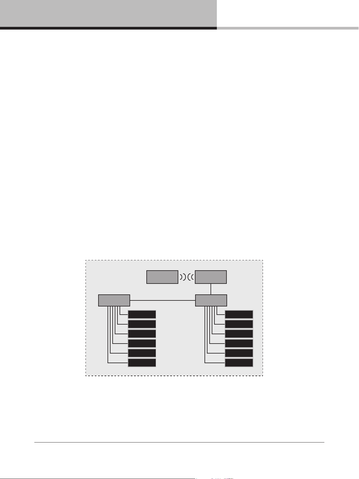
13.1. Network setup
13.1.1. Network connections/topology
Each frame has two network ports; a primary and a secondary. See the below diagram for a typical network
topology using the primary ports.
By default, the secondary ports are congured in dual redundancy mode to support a second redundant network.
The alternate conguration for the two ports is a switch mode which allows daisy–chaining devices in a single
network. Daisy chain mode is not recommended for more than a few devices, and for not more than two if running
Dante audio along with control data.
Computer
Switch
D Series Lake
D Series Lake
D Series Lake
D Series Lake
D Series Lake
D Series Lake
Wireless
Access Point
Switch
D Series Lake
D Series Lake
D Series Lake
D Series Lake
D Series Lake
D Series Lake
NOTE: If using Dante audio in the network, the audio trafc needs to be ltered from reaching the wireless links.
13.1.2. Network configuration
Frames are congured by default to obtain IP addresses automatically. The frame will assign itself an IP address
in the link local range (169.254.1.0 through 169.254.254.255). If a computer is congured the same way
D SERIES Lake Operation Manual rev 3.0.1
34
Page 35

13. System configuration tutorial
(which should be default on modern operating systems), it will reside in the same subnet as the devices and
communication can be established. Alternate congurations would be DHCP for a managed network or xed IP.
To connect to the secondary network in dual redundancy mode the computer shall be congured with an IP
address in the 172.31.0.0 – 172.31.255.255.
13.2. Software installation and firmware update
13.2.1. Lake Controller software suite
1. The Lake controller software suite includes the Lake controller and accompanying utilities: Lake LoadLibrary,
Dante discovery services and documentation. Download the Lake Controller installation from
www.labgruppen.com.
2. Execute the installer and follow the on–screen instructions. This is a typical software installation where the
default settings are acceptable for the vast majority of users.
13.2.2. CAFÉ software
1. The CAFÉ software is available as a separate installer on www.labgruppen.com.
2. Execute the installer and follow the on–screen instructions. This is a typical software installation where the
default settings are acceptable for the vast majority of users.
13.2.3. Firmware update
The latest rmware for the product is included in the Lake controller installation. It is likely that rmware installed on
the new product is older and requires updating.
1. Make sure all frames are powered on and connected through a wired network.
2. Launch the Lake rmware update utility LakeUpdate.exe.
3. Select the appropriate product range.
4. If more than one network adapter is enabled, a prompt will appear requiring selection of the adapter connected
to the frames.
5. If prompted, allow the application access through the Firewall.
6. Latest rmware is preselected.
7. Discovered frames are listed. Tap Select Old and Update to initiate rmware update of all outdated frames.
Frames already up to date will not be selected.
8. Read warning message and tap OK.
9. Wait for all updates to be completed. A wait indication will display on the unit(s) during updating.
10. Follow the on screen instructions. Ampliers with rmware associated with Lake Controller 6.5.0 or later will
automatically power cycle the mains power, whereas ampliers with older rmware will display a message that
a manual power cycle is required. (Note: A manual power cycle requires the mains plug to be completely
removed, the standby button does not complete the rmware update.)
11. If internal updates are needed, these will be performed by the frame after the power cycle. A wait indication is
displayed.
12. Tap Exit to close the update utility.
D SERIES Lake Operation Manual rev 3.0.1
35
Page 36
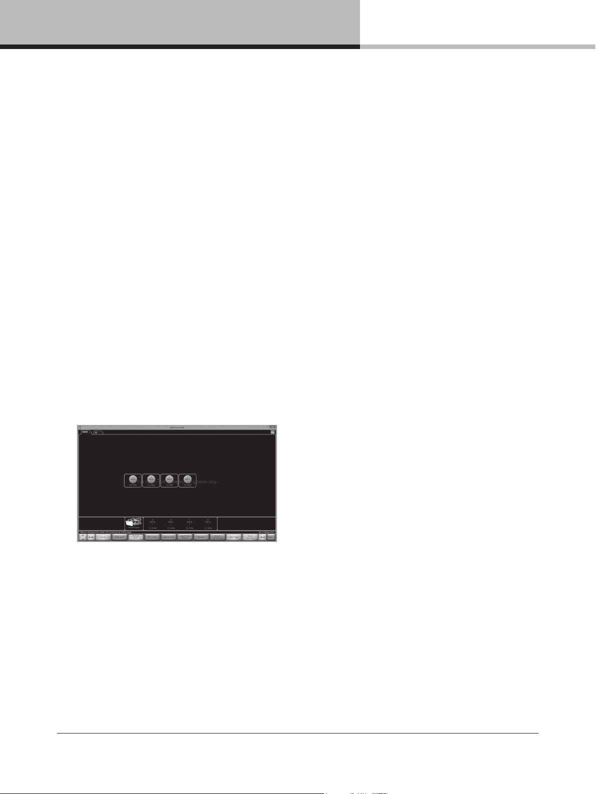
13. System configuration tutorial
13.3. System setup
This tutorial provides a step–by–step guide for conguration of a typical professional loudspeaker system and
provides an overview of the basic features and operation of the frame. This tutorial describes how to congure
4–channel frame for use with a generic 3–way loudspeaker system (with separate HF, MF and LF drivers), plus
a separate subwoofer. It assumes that the system is fed with analog outputs from a mixing console with one
fullrange main output and a separate sub feed.
1. Connect the loudspeakers to the four power output channels:
a. Channel 1 – Low Frequency Driver
b. Channel 2 – Mid Range Driver
c. Channel 3 – High Frequency Driver
d. Channel 4 – Subwoofer
2. Connect the main output of the mixing console to analog input 1 of the frame and the sub feed to input 2.
While conguring, it is a good practice to make sure the volume is turned down on the console.
3. Ensure the frame is powered on and is in its default state, and that the computer has established an active
Ethernet connection.
4. On the Tablet PC, launch the Lake Controller software application. Select the appropriate network adapter if
more than one is enabled, and tap NO to the dialog asking whether to load the previous conguration.
5. Tap MODULES button on the menu bar at the bottom of the screen to access the Module Menu and scroll
bar.
6. On the Module scroll bar, the frame is represented with a frame containing four discs. These are labeled A, B,
C and D, each representing one of the four Lake processing modules.
7. Tap the frame to select it, then tap again in the MAIN area of the screen to place all modules of the frame in
the current system conguration. The Lake Controller uploads settings from the frame.
8. Tap the icon for Module A; its border will turn yellow to conrm selection and an LED on the front panel of the
associated device will illuminate.
9. Tap the Module Store/Recall button on the Modules Menu; the menu will change to show additional options.
10. Double–tap the Default Modules folder, then double–tap the Contour Classic Crossovers folder. A set of
loudspeaker symbols will be displayed.
11. Tap CL3way, and then tap the RECALL button. This congures the DSP for the Module A as a 3–way
crossover for the 3 way speaker.
12. Tap Yes when asked to conrm that all data will be overwritten.
13. An Output conguration dialog will pop up to allow for routing of module outputs to power channels. Tap the
orange number buttons in the matrix to un–route, freeing up a power channel. Tap a blue number button at
the intersection of the appropriate module output and power channel, routing the module output to the power
channel. Proceed until you have routing according to the picture below and tap the bottom right return button
to exit the dialog.
D SERIES Lake Operation Manual rev 3.0.1
36
Page 37
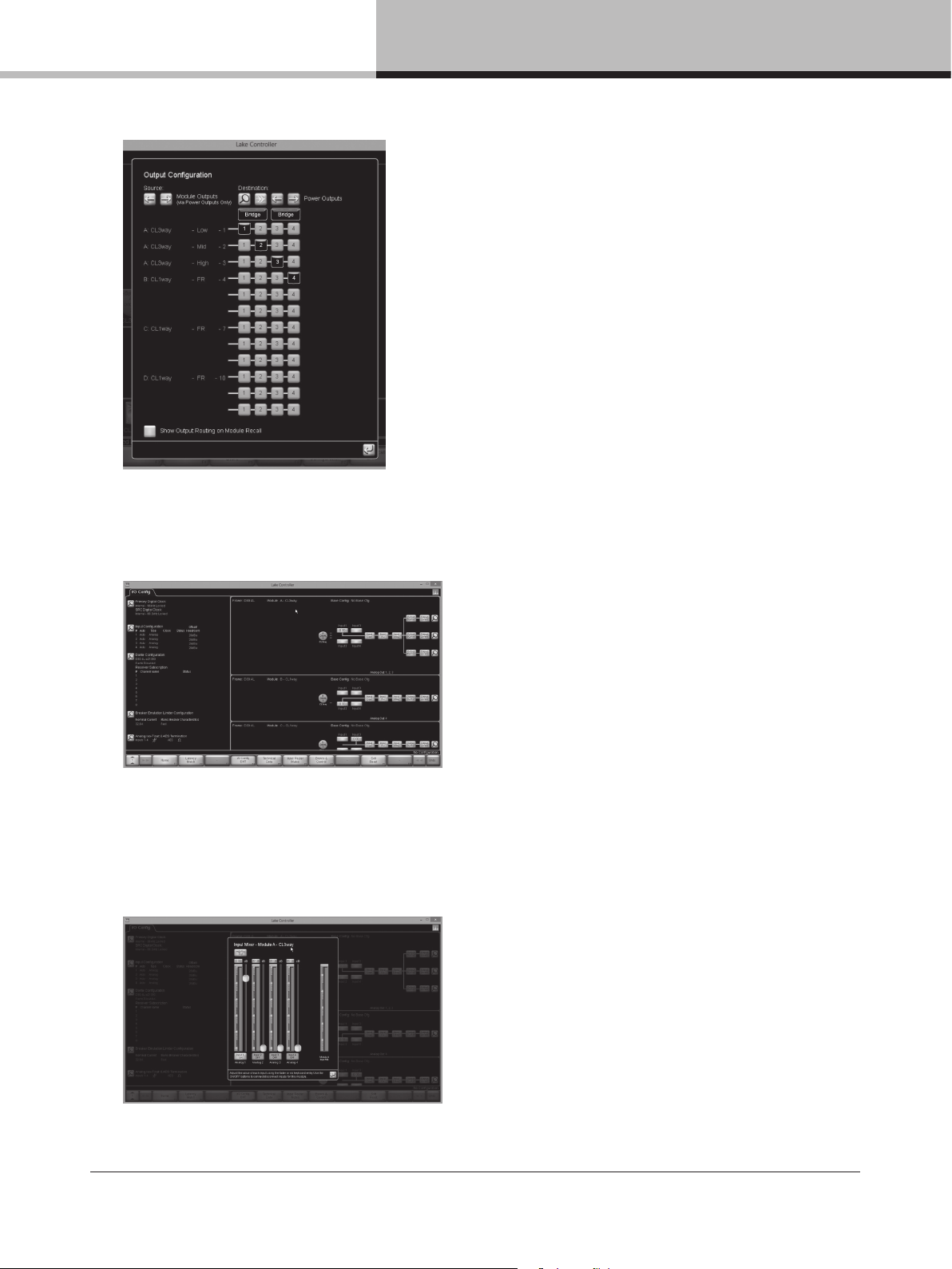
13. System configuration tutorial
1
2
3
4
Bridge Bridge
14. The B module is already a CL1way as default and can be used to drive the sub.
15. Tap Store/Recall EXIT to return to the Modules Menu.
16. Ensuring Module A (or any other module that you want to control) is selected (yellow border), tap I/O Cong.
17. The right side of the I/O CONFIG screen displays a block diagram for the Modules. Tapping the different blue
blocks will access the conguration screens for Input mixer, Levels, Input EQ, Delay and Output EQ/Crossover
respectively. The magnifying glass at the far right end accesses the output conguration. (NOTE: Tapping the
blue return button (left arrow), or the EQ/Levels EXIT button in the menu bar returns to the I/O Cong screen
from the various conguration screens.)
Input Mixer Conguration – Drag sliders and tap ON/OFF buttons to control input mixer settings.
D SERIES Lake Operation Manual rev 3.0.1
37
Page 38

13. System configuration tutorial
Levels Control – Drag sliders and tap mute buttons for module
input and output channels.
Delay Control – Drag sliders to control input and output delay Crossover control – Select lters and drag on the bottom
Parametric EQ control – Select lter on the top squares
and adjust lter properties by dragging the controls. Sliders
at the bottom control center frequency and Q (bandwidth).
Gain is controlled in the main window area. Additional lters
can be added by tapping the top lter objects and placing
new lters on the main area.
frequency bar to adjust crossover frequency. Crossover
types may be changed by selecting the Crossover
Functions button.
18. Tap the Input Gain button in the block diagram and unmute the Module Input Mute. Tap EQ/Levels Exit to return to
IO Cong.
19. The left side of the IO cong screen holds frame conguration and summary for Clock conguration, Input
conguration, Dante conguration, Breaker Emulation Limiter conguration and Analog Iso–Float & AES Termination
conguration. All these congurations should be correct by default for this example.
20. From I/O cong, tap Amplier Events & Control and navigate to the Status tab. Unmute the power channels and
slowly increase the volume on the appropriate feed from the mixing console. Audio should now be active at the
outputs and heard through the loudspeakers. Close the Amplier Events & Control dialog with the return button
and return to the main area by tapping the I/O Cong EXIT button.
Amplier Events & Control, Status tab – Drag sliders to adjust power channel attenuation and tap mute
buttons to control power channel mute. Metering and Status monitoring is available for each power channel.
D SERIES Lake Operation Manual rev 3.0.1
38
Page 39
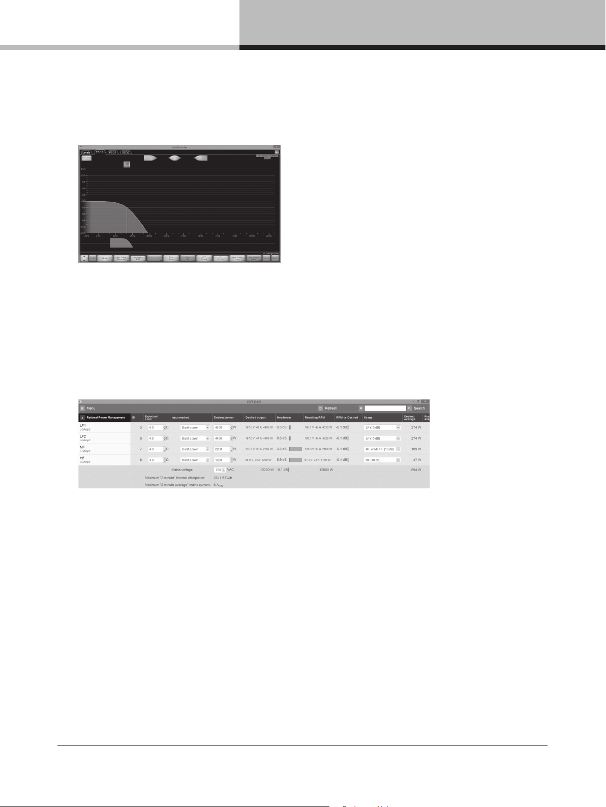
13. System configuration tutorial
21. Repeat step 16 and 20 for the B module. On the Output EQ/Crossover, tap the Aux Output Functions
button on the menu bar and then tap LPF Enable button. Drag the Low pass lter control object on the
frequency slider just above the menu bar to an appropriate crossover frequency for the sub, e.g. 100 Hz.
22. Use the control options mentioned in 17 to tune your loudspeakers. For larger systems, modules can be
placed in groups (Groups menu from the MAIN page) for control of multiple units.
23. Some features like RPM can only be congured from within CAFÉ software. Return to AMPLIFIER EVENTS
& CONTROL; from the main area hit MODULES button, select a module (e.g. Module A), tap I/O Cong,
tap AMPLIFIER EVENTS & CONTROL, and navigate to the Control tab. The CAFÉ button (next to bottom)
opens the CAFÉ application and imports and highlights the current amplier and its RPM view.
CAFÉ, RPM view – Enter power requirements and impedances for the channels to congure RPM.
13.4. Additional Software Reference Material
Additional information regarding conguration of Lake Controller for specic loudspeaker systems is available in the
Lake Controller Operation Manual, available for download in PDF format at www.labgruppen.com/support.
Additional information on conguration of CAFÉ software is available in an integrated guide in the software program
and in the CAFÉ Coach videos posted on the Lab.gruppen web site and on the Lab.gruppen channel on YouTube.
D SERIES Lake Operation Manual rev 3.0.1
39
Page 40
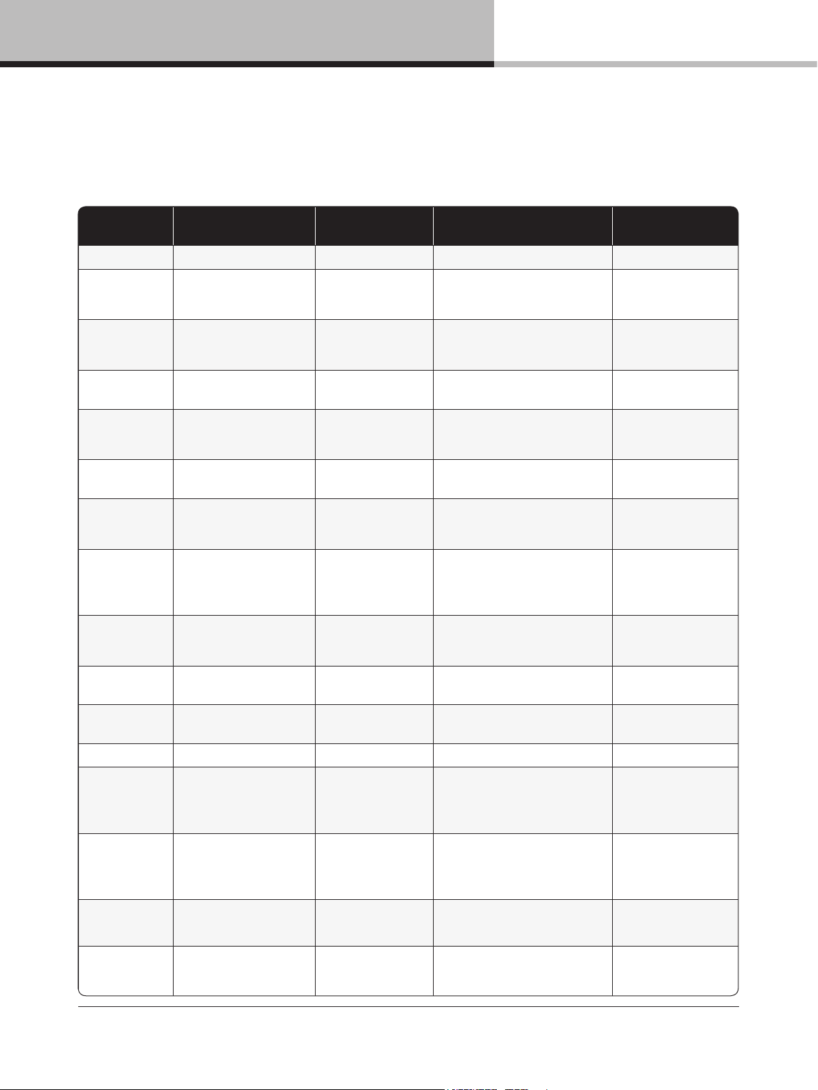
14. Appendix
Category/Type Name On screen text Description Action
FRAME
Warning
Lake Controller ofine CTRL OFFLINE
Frame unable to nd Lake controller
on the network
Check network cabling/
network if controller
expected on the network
Warning
AES / Dante clock slipping CLOCK SLIPPING
Frame not able to lock to incoming
AES stream or Dante clock slipping.
Check AES sender and
clock conguration or
Dante clock settings
Warning
Dante device na me conict NAME CONFLICT
Two or more devices on the network
with the same Dante name
Review Dante
conguration
Warning
Dante module not detected
DANTE NEEDS
SERVICE
Lake cannot detect a functioning
Dante module
Restart device; if not
cleared it needs service
to operate Dante
Warning
Dante module with
incompatible rmware
DANTE FW INVALID
Dante module not loaded
with correct FW
Retry updating the rmware
with LakeUpdate
Warning
Dante module disabled DANTE DISABLED
Dante module not communicated
correctly or other internal
conguration fault
Restart device; if not
cleared it needs service
Warning
Sense fault D SP SENS FLT:DSP
Voltage and current sensing on amplier
output fault y. Audio continues but
protection might be compromised.
No load monitoring
Restart device; if not
cleared it needs service
Warning
A/D converter power
supply fault
A/D P SU FAULT
Voltage supply to the analog input
converters faulty
Restart device; if not
cleared it needs service for
analog input to work
Fault
Audio Fault AUDIO FAULT
Internal audio interface
not functioning
Restart device; if not
cleared it needs service
Fault
DICO communication fault DICO COMM FAULT
Communication fault between host
and amplier platform
Restart device; if not
cleared it needs service
TEMP
Warning
Temperature warning
power supply
TEMP WARN:PSU
Power supply temperature
approaching critical levels
Improve cooling or reduce
output power to avoid
temperature becoming
critical
Warning
Temperature warning
DSP area
TEMP WARN:DSP
DSP area temperature approaching
critical levels
Improve cooling or reduce
output power to avoid
temperature becoming
critical
Warning
Power supply
Temperature Limit
PTL ACTIVE
Amplier is reducing output power
to avoid power supply temp
fault protection
Improve cooling or reduce
output power to avoid
limiting
Warning
Amp channel
Temperature Limit
ATL ACTIVE
Amplier channel is reducing output
power to avoid amplier channel
temp fault protection
Improve cooling or reduce
output power to avoid
limiting
Category/Type Name On screen text Description Action
Fault
Temperature fault
power supply
TE MP F LT:PS U
Power supply temperature reached
internal protection limit
Automatically restarts
when cooled down
Fault
Temperature fault
DSP area
TE MP F LT:D SP
DSP area re ached
critical temperature
Improve cooling or
reduce power
PSU
Warning
Under Voltage Limit UVL ACTIVE
The Under Volt age limiter is active a
the mains supply is approaching
the lower end of the device’s
operational voltage. Output power
is decreased to ensure mains
distribution does not collapse
Increase mains distribution
stiffness or reduce output
power to avoid limiting
Warning
Power Average Limit PA L ACT IVE
Amplier is reducing output power due
to average power or mains current
draw is above safe operating levels
Reduce output power
to avoid limiting
Warning
Breaker Emulation Limit BEL ACTIVE
Power supply is reducing mains current
draw to stay within B EL congured
nominal current and prole
Improve mains distribution
and update BEL
conguration or reduce
output power to avoid
limiting
Warning
Mains supply glitch MAINS GLITCH
Mains glitch (missing cycles) was
detected on the mains inlet
Check mains distribution/
connection
Fault
Need service NEED SERVICE:1–8 Power supply internal error
Restart device; if not
cleared it needs service
Fault
Mains voltage above
400 volt peak
MAINS>400 VPK
Power supply detects mains voltage
above 40 0 volt peak. Protective shut
down, auto restart attempt
Check mains distribution/
connection
Fault
Mains voltage above
270 V
MAINS>270 V
Power supply detects mains voltage
above operation voltage. Protective
shut down, auto restart attempt
Check mains distribution/
connection
Fault
Mains voltage below
65 V
Mains<65 V
Power supply detects mains voltage
below operation voltage. Protective
shut down, auto restart attempt
Check mains distribution/
connection
Fault
Power supply fault PS U FAULT Internal power supply fault
Check mains distribution/
connection. Restart
device; if not cleared
it needs service
Fault
Check mains CHECK MAINS
Power supply detects unstable
mains supply. Protective shut down,
auto restart attempt
Check mains distribution/
connection
Fault
Power supply power protect PSU POWER PROT
Too high output power for too low
mains supply voltage. Protective
shut down, auto restart attempt
Improve mains supply
voltage or reduce
output power
LOAD
Warning
Speaker short SPKR SHORT Both LoadPilot tones below thresholds Check load or calibration
Warning
Speaker damaged SPK R DAMAGED
One LoadPilot tone is above
or below threshold
Check load or calibration
14. Appendix
14.1. Faults and warnings
40
D SERIES Lake Operation Manual rev 3.0.1
Page 41
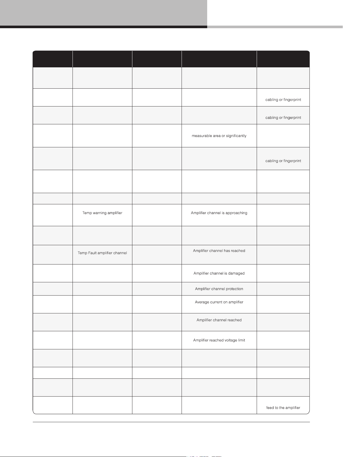
14. Appendix
Category/Type Name On screen text Description Action
Warni ng
Under speaker count UNDER S PKR CNT
Both LoadPilot tones above
thresholds or LoadSmart detected
fewer speakers than expected
Check load, cabling and
calibration
Warni ng
More speakers OVR SPKR COUNT
LoadSmart detected more speakers
than expected
Check load and
Warni ng
Uncertain about load UNCERTAIN LOAD LoadSmart uncer tain about load
Check load and
Fault
No load NO LOAD
At least one LoadPilot tone above
above thresholds
Check load or calibration
Fault
Wrong load WRONG LOAD
LoadSmart detected impedance
response output model
Check load and
Fault
Short circuit SHORT CIR CUIT
LoadPilot or full frequency analysis
below short threshold or hardware
short protection
Check load and cabling
AMP
Warni ng
channel
TEMP WARN
critical temperature
Improve cooling or reduce
output power to avoid
temperature becoming
critical
Fault
TEMP FAULT
internal protection limit
Automatically unmutes
when cooled down
Warning
(D200, D120, D80 only)
VHF WARNINGVery high frequency warning
Amplifier channel gain
reduction due to VHF content
Check input signal
Fault
Service channel SERVICE C H.
Restart device; if not
cleared it needs service
Fault
Very high frequency fault VHF FAULT
Check input signal
Fault
Current average limiter CAL ACTIVE
above safe operating level
Reduce output power
to avoid limiting
Clip
Current clip CURRENT CLIP
current limit
Reduce output power
to avoid limiting
Clip
Voltage clip VOLTAGE CLIP
Reduce output power
to avoid limiting
Clip
Module clip MOD. CLIP Module output signal clipped
Review gain structure.
Module gain vs A mpGain
SIGNAL
Fault
No input source NO INPUT
Input router has no valid
input source
Review input router
settings/connections
Clip
Analog/AES input clip INPUT CLIP
The signal on the analog/AES input
is above inputs capability
Lower the signal on the
D SERIES Lake Operation Manual rev 3.0.1
41
Page 42
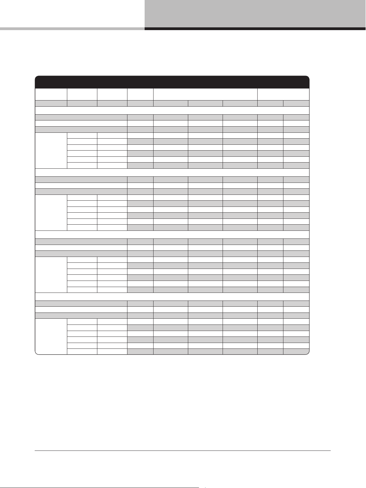
14.2. Current draw and thermal dissipation
D SERIES 10:4
Level Load
Rated power
per channel
Line Cu rrent Measured Power (W) Thermal Dissipation
(A) In Out Dissipated BTU/hr kCal/hr
Mains Voltage 100 VAC
Standby
0.1 7 0 7 24 6
Power On , Idling, Green Mod e
0.5 45 0 45 153 38
Power On , Idling, Perform ance Mode
0.7 71 0 71 241 61
Pink Pseudo
Noise
16 Ω / Ch. 250 x 4 2.3 229 125 104 355 89
8 Ω / Ch. 250 x 4 2.4 240 125 115 391 98
4 Ω / Ch. 250 x 4 2.6 254 125 12 9 439 111
2 Ω / Ch. 250 x 4 2.8 279 125 15 4 527 133
100 V / Ch. 175 x 4 1.8 17 9 88 92 313 79
70 V / Ch. 250 x 4 2.3 230 125 105 358 90
Mains Voltage 120 VAC
Standby
0.1 7 0 7 24 6
Power On , Idling, Green Mod e
0.4 44 0 44 152 38
Power On , Idling, Perform ance Mode
0.6 70 0 70 238 60
Pink Pseudo
Noise
16 Ω / Ch. 250 x 4 1.9 228 125 103 350 88
8 Ω / Ch. 250 x 4 2.0 238 125 113 386 97
4 Ω / Ch. 250 x 4 2.1 252 125 127 433 109
2 Ω / Ch. 250 x 4 2.3 277 125 152 519 131
100 V / Ch. 175 x 4 1.5 17 9 88 91 311 78
70 V / Ch. 250 x 4 1.9 229 125 103 353 89
Mains Voltage 208 VAC
Standby
0.1 7 0 7 24 6
Power On , Idling, Green Mod e
0.3 42 0 42 142 36
Power On , Idling, Perform ance Mode
0.4 66 0 66 225 57
Pink Pseudo
Noise
16 Ω / Ch. 250 x 4 1.1 221 125 96 328 83
8 Ω / Ch. 250 x 4 1.1 228 125 103 353 89
4 Ω / Ch. 250 x 4 1.2 245 125 120 408 103
2 Ω / Ch. 250 x 4 1.3 269 125 14 4 493 124
100 V / Ch. 175 x 4 0.9 174 88 86 294 74
70 V / Ch. 250 x 4 1.1 222 125 97 332 84
Mains Voltage 230 VAC
Standby
0.1 7 0 7 25 6
Power On , Idling, Green Mod e
0.3 41 0 41 141 36
Power On , Idling, Perform ance Mode
0.3 65 0 65 222 56
Pink Pseudo
Noise
16 Ω / Ch. 250 x 4 1.0 218 12 5 93 317 80
8 Ω / Ch. 250 x 4 1.0 225 125 100 342 86
4 Ω / Ch. 250 x 4 1.1 238 125 113 387 97
2 Ω / Ch. 250 x 4 1.2 263 125 13 8 472 119
100 V / Ch. 175 x 4 0.8 168 88 81 275 69
70 V / Ch.
250 x 4 1.0 216 12 5 91 311 78
14. Appendix
D SERIES Lake Operation Manual rev 3.0.1
42
Page 43
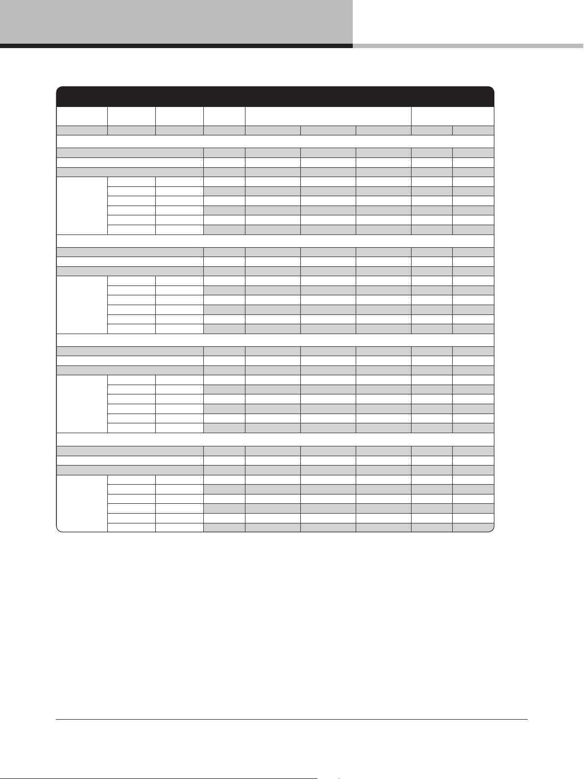
14. Appendix
D SERIES 20:4
Level Load
Rated power
per channel
Line Cu rrent Measured Power (W) Thermal Dissipation
(A) In Out Dissipated BTU/hr kCal/hr
Mains Voltage 100 VAC
Standby
0.2 7 0 7 24 6
Power On , Idling, Green Mod e
0.5 46 0 46 157 39
Power On , Idling, Perform ance Mode
0.7 71 0 71 243 61
Pink Pseudo
Noise
16 Ω / Ch. 425 x 4 2.9 348 213 136 463 117
8 Ω / Ch. 50 0 x 4 3.5 418 250 168 573 144
4 Ω / Ch. 50 0 x 4 3.7 444 250 194 662 16 7
2 Ω / Ch. 50 0 x 4 4.1 492 250 242 825 208
100 V / Ch. 250 x 4 1.9 230 125 105 360 91
70 V / Ch. 500 x 4 3.5 410 250 16 0 546 138
Mains Voltage 120 VAC
Standby
0.1 7 0 7 23 6
Power On , Idling, Green Mod e
0.4 45 0 45 155 39
Power On , Idling, Perform ance Mode
0.6 71 0 71 241 61
Pink Pseudo
Noise
16 Ω / Ch. 425 x 4 2.9 346 213 134 457 115
8 Ω / Ch. 50 0 x 4 3.5 411 250 161 550 139
4 Ω / Ch. 50 0 x 4 3.7 441 250 190 650 16 4
2 Ω / Ch. 50 0 x 4 4.1 487 250 237 810 204
100 V / Ch. 250 x 4 2.0 231 12 5 10 6 361 91
70 V / Ch. 500 x 4 3.4 408 250 158 540 13 6
Mains Voltage 208 VAC
Standby
0.1 7 0 7 24 6
Power On , Idling, Green Mod e
0.3 43 0 43 147 37
Power On , Idling, Perform ance Mode
0.4 67 0 67 229 58
Pink Pseudo
Noise
16 Ω / Ch. 425 x 4 1.5 336 213 124 422 106
8 Ω / Ch. 50 0 x 4 1.8 398 250 14 8 506 127
4 Ω / Ch. 50 0 x 4 1.9 426 250 176 600 151
2 Ω / Ch. 50 0 x 4 2.1 471 250 221 753 190
100 V / Ch. 250 x 4 1.0 224 125 99 339 85
70 V / Ch. 500 x 4 1.8 395 250 14 5 496 125
Mains Voltage 230 VAC
Standby
0.2 7 0 7 24 6
Power On , Idling, Green Mod e
0.3 43 0 43 146 37
Power On , Idling, Perform ance Mode
0.4 67 0 67 227 57
Pink Pseudo
Noise
16 Ω / Ch. 425 x 4 1.5 333 213 12 0 411 104
8 Ω / Ch. 50 0 x 4 1.8 394 250 14 4 493 124
4 Ω / Ch. 50 0 x 4 1.9 419 250 169 577 145
2 Ω / Ch. 50 0 x 4 2.1 467 250 217 741 187
100 V / Ch. 250 x 4 1.0 222 125 97 331 83
70 V / Ch.
500 x 4 1.8 392 250 142 484 122
D SERIES Lake Operation Manual rev 3.0.1
43
Page 44
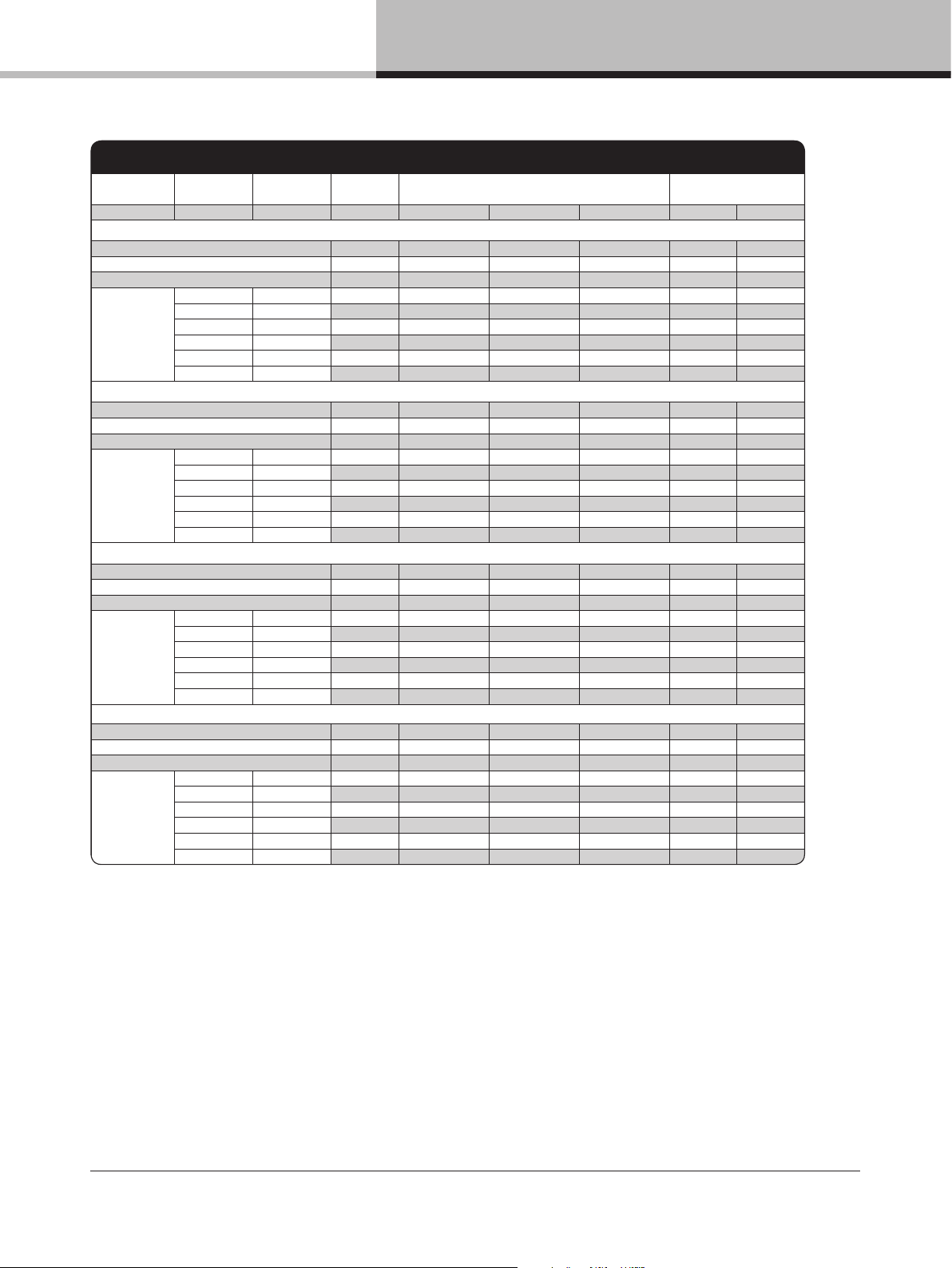
14. Appendix
D SERIES 40:4
Level Load
Rated power
per channel
Line Cu rrent Measured Power (W) Thermal Dissipation
(A) In Out Dissipated BTU/hr kCal/hr
Mains Voltage 100 VAC
Standby
0.2 7 0 7 24 6
Power On , Idling, Green Mod e
0.6 59 0 59 201 51
Power On , Idling, Perform ance Mode
0.8 78 0 78 267 67
Pink Pseudo
Noise
16 Ω / Ch. 700 x 4 5 .1 502 350 152 518 131
8 Ω / Ch. 1000 x 4 7.2 709 500 209 714 180
4 Ω / Ch. 1000 x 4 7.6 754 500 254 868 219
2 Ω / Ch. 80 0 x 4 7.0 689 400 289 986 249
100 V / Ch. 1000 x 4 7.1 701 500 20 0 684 172
70 V / Ch. 1000 x 4 7.5 738 500 238 812 205
Mains Voltage 120 VAC
Standby
0.2 7 0 7 24 6
Power On , Idling, Green Mod e
0.5 59 0 59 200 50
Power On , Idling, Perform ance Mode
0.7 77 0 77 263 66
Pink Pseudo
Noise
16 Ω / Ch. 700 x 4 4.2 497 350 147 503 127
8 Ω / Ch. 1000 x 4 5.9 700 500 19 9 681 172
4 Ω / Ch. 1000 x 4 6.3 743 500 243 829 209
2 Ω / Ch. 80 0 x 4 5.7 679 400 279 953 240
100 V / Ch. 1000 x 4 5.8 690 500 190 648 163
70 V / Ch. 1000 x 4 6.1 726 500 226 772 195
Mains Voltage 208 VAC
Standby
0.3 7 0 7 25 6
Power On , Idling, Green Mod e
0.5 58 0 58 198 50
Power On , Idling, Perform ance Mode
0.5 77 0 77 263 66
Pink Pseudo
Noise
16 Ω / Ch. 700 x 4 2.2 486 350 136 464 117
8 Ω / Ch. 1000 x 4 3.1 6 81 500 181 617 155
4 Ω / Ch. 1000 x 4 3.3 723 500 223 759 191
2 Ω / Ch. 80 0 x 4 3.0 662 400 261 892 225
100 V / Ch. 1000 x 4 3.0 673 500 17 3 589 14 8
70 V / Ch. 1000 x 4 3.2 707 500 207 707 178
Mains Voltage 230 VAC
Standby
0.3 7 0 7 25 6
Power On , Idling, Green Mod e
0.4 58 0 58 197 50
Power On , Idling, Perform ance Mode
0.5 77 0 77 263 66
Pink Pseudo
Noise
16 Ω / Ch. 700 x 4 2.2 474 350 124 423 106
8 Ω / Ch. 1000 x 4 3.0 664 500 16 4 558 141
4 Ω / Ch. 1000 x 4 3.2 705 500 205 701 176
2 Ω / Ch. 80 0 x 4 3.0 649 400 249 850 214
100 V / Ch. 1000 x 4 3.0 659 500 159 544 137
70 V / Ch. 1000 x 4 3.2 694 500 194 661 166
D SERIES Lake Operation Manual rev 3.0.1
44
Page 45
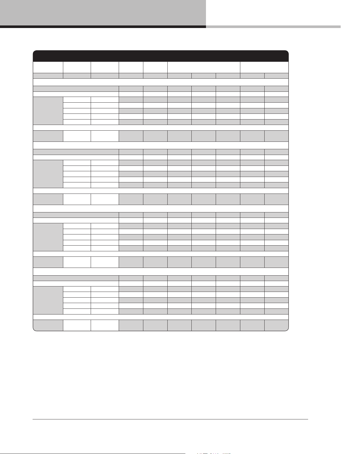
14. Appendix
D SERIES 80:4
Level Load
Rate d power
per ch annel
Line Cu rrent
Power
Facto r
Meas ured Power ( W) Thermal D issipat ion
(A) (%) In Out Dis sipated BTU /hr kCal/ hr
Mains Vo ltage 100 VAC, 30 A
Standby 0.3 4 3 11 0 11 3 6 9
Power on , Idling 2.1 99 204 0 2 04 696 175
Pink Ps eudo
Nois e
16 Ω / Ch. 750 10.1 99 981 37 5 607 20 70 522
8 Ω / Ch. 15 00 15.3 99 14 92 749 743 25 34 639
4 Ω / Ch. 20 00 14.9 99 1502 6 52 850 29 00 731
2.67 Ω / Ch. 2000 15.3 9 9 1539 6 25 914 3120 7 87
2 Ω / Ch. 20 00 15.2 99 15 38 56 0 978 33 37 841
LoadP ilot
Sine 20 k Hz
8 Ω / Ch. 2.2 9 8 211 0 211 72 0 181
M
ains Volta ge 120 VAC, 30 A
Stan dby 0.3 3 5 11 0 11 37 9
Powe
r on, Idl ing 1.8 9 8 202 0 202 689 174
Pink Ps eudo
Nois e
16 Ω / Ch. 750 8.0 99 9 54 375 579 1977 499
8 Ω / Ch. 15 00 12.6 99 1476 74 9 727 24 80 625
4 Ω / Ch. 20 00 14.4 99 1739 817 923 3148 794
2.67 Ω / Ch. 2000 14.7 9 9 1780 76 6 1014 3 461 873
2 Ω / Ch. 20 00 15.2 99 18 39 73 9 1101 375 5 947
LoadP ilot
Sine 20 k Hz
8 Ω / Ch. 1.8 9 8 211 0 211 719 181
Mains Vo ltage 208 VAC, 17.3 A
Standby 0.3 17 11 0 11 39 10
Power on , Idling 1.1 91 197 0 197 673 170
Pink Ps eudo
Nois e
16 Ω / Ch. 750 4.6 99 927 375 55 2 18 84 475
8 Ω / Ch. 15 0
0 7.1 99 1436 749 6 87 2 345 5 91
4 Ω / Ch. 20 0
0 9.3 10 0 1955 10 00 955 3260 822
2.67 Ω / Ch. 2000 9. 8 10 0 2 087 1003 10 84 369 8 93 3
2 Ω / Ch. 20 00 10.3 100 2182 1001 1181 4 030 1016
LoadP ilot
Sine 20 k Hz
8 Ω / Ch. 1.1 9 2 20 4 0 204 69 5 175
Mains Vo ltage 230 VAC, 16 A
Standby 0.3 17 12 0 12 39 10
Power on , Idling 1.0 89 193 0 193 6 60 166
Pink Ps eudo
Nois e
16 Ω / Ch. 750 4.2 99 9 48 375 573 1957 493
8 Ω / Ch. 15 00 6.4 99 1443 749 6 94 236 9 5 97
4 Ω / Ch. 20 00 8.1 99 1907 10 00 9 06 309 2 78 0
2.67 Ω / Ch. 2000 8.7 100 2 052 1003 10 49 3 580 9 03
2 Ω / Ch. 20 00 9.4 10 0 2 200 1000 1201 409 6 10 33
LoadP ilot
Sine 20 k Hz
8 Ω / Ch. 1.0 8 9 2
04 0 20 4 6 95 175
D SERIES Lake Operation Manual rev 3.0.1
45
Page 46
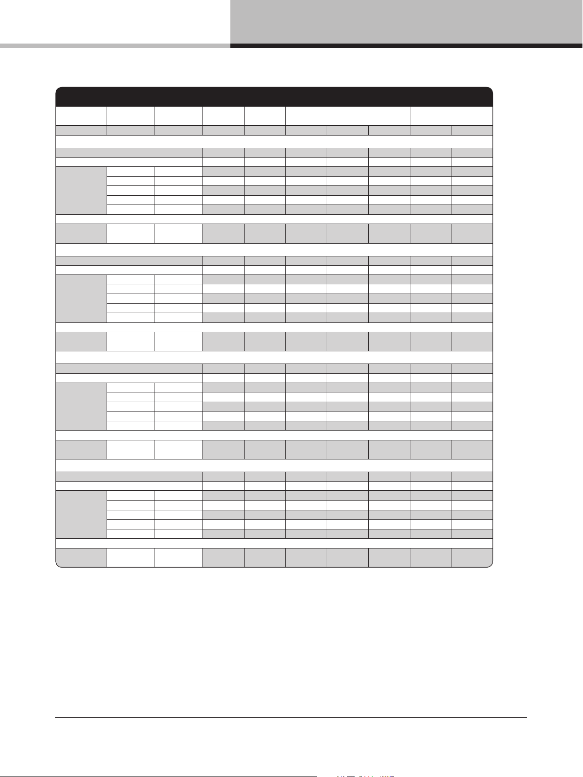
D SERIES 120:4
Level Load
Rate d power
per ch annel
Line Curr ent
Power
Facto r
Measur ed Power (W) Therma l Dissip ation
(A) (%) In Out Dis sipated BT U/hr kCal/ hr
Main s Voltage 100 VAC, 30 A
Stan dby 0.3 4 3 12 0 12 4 0 10
Power on, I dling 2.3 98 219 0 219 749 18 9
Pink Ps eudo
Noise
16 Ω / Ch. 950 10.8 99 10 59 475 5 84 19 94 503
8 Ω / Ch. 19 00 19.2 99 1868 949 919 3136 791
4 Ω / Ch. 3000 24. 6 9 9 2389 120 0 1189 40 57 1023
2.67 Ω / Ch. 3000 25 .7 9 9 2551 1151 140 0 4776 1204
2 Ω / Ch. 3000 25. 8 9 9 2576 1113 146 3 4 992 1259
LoadP ilot
Sine 20 kHz
8 Ω / Ch. 2.4 9 8 2 31
0 231 7 89 199
Main s Voltage 120 VAC, 30 A
Stan dby 0.3 3 6 11 0 11 3
9 10
Power on, I dling 1.9 98 215 0 2 15 734 185
Pink Ps eudo
Noise
16 Ω / Ch. 950 8.8 99 1035 475 5 60 1910 482
8 Ω / Ch. 19 00 15.1 99 1765 94 9 8 15 2 783 702
4 Ω / Ch. 3000 24. 0 9 9 2817 150 2 1315 44 87 1131
2.67 Ω / Ch. 3000 24. 5 9 9 2894 143 7 1456 4969 125 3
2 Ω / Ch. 3000 2 5.1 9 9 2980 136 1 1619 55 24 1393
LoadP ilot
Sine 20 kHz
8 Ω / Ch. 2.0 9 7 22 6 0 226 77 3 195
Main s Voltage 208 VAC, 17.3 A
Stan dby 0.3 18 12 0 12 42 11
Power on, I dling 1.1 91 211 0 211 72 0 182
Pink Ps eudo
Noise
16 Ω / Ch. 950 4.9 99 1
001 475 52 6 1795 453
8 Ω / Ch. 19 00 8.7 99 1766 949 816 278 6 702
4 Ω / Ch. 3000 1
3.3 9 9 2 687 1501 1186 40 46 1020
2.67 Ω / Ch. 3000 14. 0 9 9 2847 150 0 1346 45 94 1158
2 Ω / Ch. 3000 14. 8 9 9 3046 150 0 1546 52 76 1330
LoadP ilot
Sine 20 kHz
8 Ω / Ch. 1.2 9 3 2 21 0 221 75 4 190
Main s Voltage 230 VAC, 16 A
Stan dby 0.3 18 13 0 13 43 11
Power on, I dling 1.0 90 205 0 20 5 698 176
Pink Ps eudo
Noise
16 Ω / Ch. 950 4.7 99 1003 475 5 29 1803 455
8 Ω / Ch. 19 00 7.7 99 1734 949 7 84 2676 675
4 Ω / Ch. 3000 11.4 99 25 62 1501 1061 3 620 913
2.67 Ω / Ch. 3000 12. 8 9 9 2873 1499 1374 4688 1182
2 Ω / Ch.
3000 13.1 9 9 2 993 1500 1493 50 95 1285
LoadP il
ot
Sine 20 kHz
8 Ω / Ch. 1.0 9 0 2 14 0 214 73 0 184
14. Appendix
46
D SERIES Lake Operation Manual rev 3.0.1
Page 47
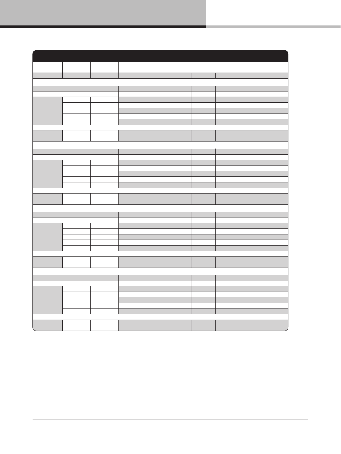
14. Appendix
D SERIES 200:4
Level Load
Rate d power
per ch annel
Line Curr ent
Power
Facto r
Measur ed Power (W) Therma l Dissip ation
(A) (%) In Out Dis sipated BT U/hr kCal/ hr
Main s Voltage 100 VAC, 30 A
Stan dby 0.3 5 2 17 0 17 58 15
Power on, I dling 2.4 97 235 0 23 5 802 202
Pink Ps eudo
Noise
16 Ω / Ch. 1150 12.1 99 1192 5 88 604 2 061 520
8 Ω / Ch. 23 00 22.3 99 2198 1174 1024 3 493 88 1
4 Ω / Ch. 44 00 29 .2 9 9 28 53 1478 13 75 4691 1183
2.67 Ω / Ch. 5000 29.2 9 9 2 862 1399 1463 4 991 1259
2 Ω / Ch. 44 00 2 9.1 9 9 28 26 1355 1472 5 022 1266
LoadP ilot
Sine 20 kHz
8 Ω / Ch. 2
.5 97 236 0 236 807 20 3
Main s Voltage 120 VAC, 30 A
Stan dby 0.3 4 8 17 0 17 5
8 15
Power on, I dling 2.0 97 227 0 22 7 775 195
Pink Ps eudo
Noise
16 Ω / Ch. 1150 12.0 99 1180 5 88 593 2 023 510
8 Ω / Ch. 23 00 18.4 99 2144 1174 970 33 10 8 35
4 Ω / Ch. 44 00 30.0 9 9 3457 189 6 1561 53 26 1343
2.67 Ω / Ch. 5000 29.5 9 9 3 439 1752 1687 5 756 1451
2 Ω / Ch. 44 00 29 .9 9 9 34 95 16 65 1830 6 245 1575
LoadP ilot
Sine 20 kHz
8 Ω / Ch. 2.0 9 7 23 2 0 232 79 0 199
Main s Voltage 208 VAC, 17.3 A
Stan dby 0.3 2 7 18 0 18 60 15
Power on, I dling 1.2 92 222 0 22 2 757 191
Pink Ps eudo
Noise
16 Ω /
Ch. 1150 5.7 9 9 1151 58 8 56 4 1923 48 5
8 Ω / Ch. 23 00 10.2 99 2 055 1174 881 3 005 75 8
4 Ω / Ch
. 44 00 16 .2 99 328 6 1948 133 8 456 5 1151
2.67 Ω / Ch. 5000 15.6 9 9 3171 1752 1419 4 843 1221
2 Ω / Ch. 44 00 16. 0 9 9 32 53 1665 15 89 5420 13 67
LoadP ilot
Sine 20 kHz
8 Ω / Ch. 1.2 9 2 22 9 0 229 78 0 197
Main s Voltage 230 VAC, 16 A
Stan dby 0.3 2 3 18 0 18 61 15
Power on, I dling 1.2 92 222 0 22 2 757 191
Pink Ps eudo
Noise
16 Ω / Ch. 1150 5.1 98 1134 5 88 546 18 63 470
8 Ω / Ch. 23 00 9.2 99 205 3 1174 87 9 29 99 75 6
4 Ω / Ch. 44 00 15. 9 9 9 35 29 2109 142 0 4845 122 2
2.67 Ω / Ch. 5000 16.0 9 9 3 564 1935 1630 5 561 1402
2 Ω / Ch. 44 00 16. 0 9 9 35 77 1856 172 2 5875 14 8
1
LoadP ilot
Sine 20 kHz
8 Ω / Ch. 1.1 9 0 22 8 0 228 777 19 6
D SERIES Lake Operation Manual rev 3.0.1
47
Page 48

14. Appendix
14.3. Maintenance
During normal operation a D Series device provides trouble–free service. If the front panel display requires cleaning,
use a soft cloth only; do not use solvent cleaners.
The dust lters on both sides of the front panel, behind the grilles, should occasionally be removed and cleaned to
ensure maximum airow through the device. Disconnect the unit from mains power prior to removing dust the lter,
and ensure the dust lter is replaced prior to turning the unit back on.
In extreme cases it may be necessary to clean the inside of the device. This procedure should only be carried out
by qualied service personnel. Internal cleaning may be necessary if the device has had prolonged operation in an
extreme environment such as one where cracked oil smoke machines are in use. If the device is used in extreme
conditions, it is recommended to have it serviced every three years as a preventative measure.
D SERIES Lake Operation Manual rev 3.0.1
48
Page 49
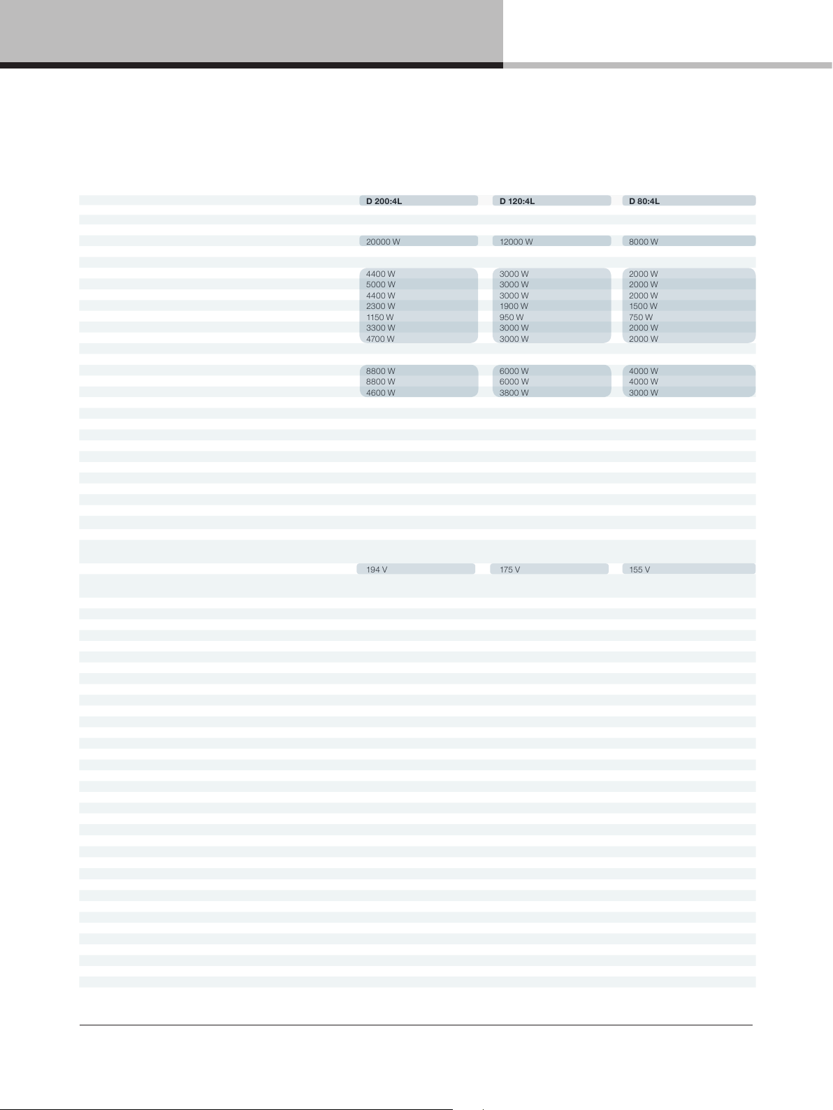
15. Technical Specifications
15. Technical Specifications
General
Processing / Network Lake / Dante Lake / Dante Lake / Dante
Number of amplier channels 4 4 4
Total burst power all channels (share among channels with RPM) 20000 W 12000 W 8000 W
Max. O utput Power (all ch.’s driven)
2 ohms 4400 W 3000 W 2000 W
2.67 ohms 5000 W 3000 W 2000 W
4 ohms 4400 W 3000 W 2000 W
8 ohms 2300 W 190 0 W 1500 W
16 oh ms 1150 W 950 W 750 W
Hi-Z 70 V 3300 W 3000 W 2000 W
Hi-Z 100 V 4700 W 3000 W 2000 W
Max. O utput power bridged mode (all ch.’s driven)
4 ohms 8800 W 6000 W 4000 W
8 ohms 8800 W 6000 W 4000 W
16 oh ms 4600 W 3800 W 3000 W
Max output powe r single channel (all model s)
2 ohms 4400 W
2.67 ohms 5900 W
4 ohms 4600 W
8 ohms 2300 W
16 oh ms 1150 W
Hi-Z 70 V 3300 W
Hi-Z 100 V 4700 W
Amplier output modules (all models, all channels)
Peak output voltage 194 V
Max output current 67 A
Rational Power Management (RPM)
Default voltage limitation (can be lifted with RPM conguration) 194 V 175 V 155 V
Protection features Current Average Limiter (CAL), Very High Frequency Protection (VHF), Direct Current Protection (DC),
1)
1)
1)
D 200:4L D 120:4L D 80:4L
Share “ total burst pow er” of the produ ct freely amo ng channel s. Any channe l can scale up to th e “Max. outp ut
power single channel”
Short Circuit Protection, Current-Clip Limiter, Voltage Clip Limiter, Temperature protection
Amplier platform
Inter Sample Voltage Peak Limiter (ISVPL) Congurable Peak voltage threshold and prole
Amplier gain Digital congurable amplier gain 22 - 44 dB
Pilot tone generation and analysis LoadPilot
Load impedance analysis
Temperature control Regulated fans and show must go on limitation (ATL, PTL)
Audio Performance (Amplier platform with digital input)
THD + N 20 Hz - 20 kHz for 1 W < 0.05 %
THD + N at 1 kHz and 1 dB below clipping < 0.04 %
Dynamic range > 114 dB
Channel separation (Crosstalk) at 1 kHz > 70 dB
Frequency response (1 W into 8 ohm, 20 Hz - 20 kHz) +/- 0.05 dB
Internal sample rate / Data path 48 / 96 kHz / 32 bit oating point
Product propagation delay AES 96 kHz / analog input 1.61 / 1.68 ms
Lake processing
Loudspeaker processing Up to 4 modules of Classic/linear-phase/FIR crossover, EQ, delay, LimiterMa x™ - peak and RMS limiters
System tuning Group control with Raised Cosine™ MESA EQ™ asymmetric lters
Input redundancy / Matrix Automatic 4 level input redundancy / 4 input mixers
System integration Comprehensive 3rd party protocol over UDP Ethernet
Dante Audio Net work
Dante I/O 8 x 8
Network topology / redundancy Flexible topology / Supports daisy-chained and Dual redundant networks
Sample rates / transport 48, 96 kHz / Uni + Multicast
Network latency 0.25, 0.5, 1.0, 2.0, 5.0 ms
Analog inputs
Inputs 4 high quality inputs with Iso-Float ground isolation
Maximum input / digital reference + 26 dBu / +21 dBu
Sampling rate / resolution 9 6 kHz / 24 bit
Input impedance balanced / unbalanced 20 / 10 kOhm
THD + N (typical at 1 kHz unweighted) 0.00022 %
THD + N (typical at 20 Hz and 20 kHz unweighted) 0.00033 %
Yes
D SERIES Lake Operation Manual rev 3.0.1
49
Page 50
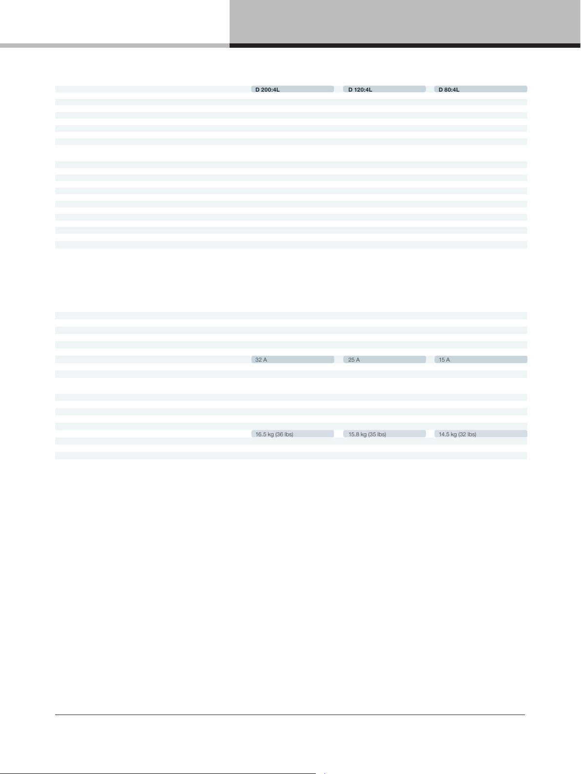
15. Technical Specifications
AES Inputs
Inputs 2 AES inputs (4 audio channels)
Supported sample rates / resolution 44.1, 48, 88.2, 96, 176.4, 192 kHz / up to 24 bit
Sample rate conversion THD + N 20 Hz - 20 kHz unweighted 0.00003 %
Rear panel inte rface
Analog inputs 4 x Terminal block connectors along input with +, – and ground
AES inputs 2 x Terminal block connectors
Output connectors
Ethernet ports
Detachable mains cord Neutrik PowerCon rated at 250 V / 32 A
Front panel user interface
System status indication 3 x tri-color LED. FRAME, TEMP, PSU for device status indication
Channel status indication 3 x tri-color LED per channel. Status indication separate d for channel LOAD, AMP, SIGNAL status
Mute Per channel touch button for MUTE control and tri-color LED for indication
Power Touch button for ON/STANDBY control and tri-color LED for power state indication
Select Touch button and LED for bi-directional device software select functionality
Mains Power
Nominal voltage 100 – 240 V AC 50 – 60 Hz
Operating voltage 70 – 265 V AC 45 – 66 Hz
Mains wall plug
Power supply features
Soft start / Inrush power Yes / Max 8 A
Power factor correction > 0.98 for mains power > 400 W
Regulated switch mode power supply (R.SMPS) Yes
Breaker Emulation Limiter (BEL) Congurable current threshold and breaker prole
BEL max current threshold 32 A 25 A 15 A
Power Average Limiter (PAL) Yes
Under Voltage Limite r (UVL) Yes
Mains undervoltage and overvoltage protection and
mains glitch tolerance
Dimensions
Rack rail to rear panel W: 483 mm (19”), H: 88 mm (2 U), D: 424 mm (16”)
Overall all depth front–rear support D: 463 mm
Weight
Finish
Approvals
D 200:4L D 120:4L D 80 :4L
4 x 2 pole Terminal block connectors rated at 1000 V / 76 A (exceeding amplier capacity)
Can take up to 16 mm
2 x EtherCon RJ 45 100 /100 0 Ba se –T fo r the Lake Co ntroller, Dan te co ntr oll er an d/o r DLM (3 rd part y pr otocol )
Selectable on order
CEE 7/7 “Schuko” 230 V / 16 A,
NEMA L5–30 “Twistlock” 125 V / 30 A,
NEMA 5–15P 125 V / 15 A (D 80:4 only),
NEMA 5–20P 125 V / 20 A (D120:4 only),
NEMA 6–20P 250 V / 20 A,
AS/NZS 3112 230 V / 15 A (Aus/Nz),
BS 546 230 V / 16 A (India),
C–30P 125V / 30A (Japan)
Yes
16.5 kg (36 lbs) 15.8 kg (35 lbs) 14.5 kg (32 lbs)
Black painted steel chassis with grey painted steel front with detachable grille
CE, ETL (A NSI/UL, CSA), PSE, RCM
2
(6 AWG) cables
Note 1): Lab.gruppen burst power (1 kHz, 25 ms burst power @ 150 BPM, 12 dB Crest factor)
All specifications are subject to change without notice.
D SERIES Lake Operation Manual rev 3.0.1
50
Page 51

15. Technical Specifications
General
Processing / Network Lake / Dante Lake / Dante Lake / Dante
Number of amplier channels 4 4 4
Total burst power all channels (share among channels with RPM) 4000 W 2000 W 1000 W
Max. O utput Power (all ch.’s driven)
2 ohms 800 W 500 W 250 W
2.67 ohms 1000 W 500 W 250 W
4 ohms 1000 W 500 W 250 W
8 ohms 1000 W 500 W 250 W
16 oh ms 700 W 425 W 250 W
Hi-Z 25 V 500 W 500 W 250 W
Hi-Z 70 V 1000 W 500 W 250 W
Hi-Z 100 V 1000 W 250 W 175 W
Max output powe r single channel
2 ohms 850 W 850 W 850 W
2.67 ohms 1150 W 115 0 W 1000 W
4 ohms 1750 W 1600 W 1000 W
8 ohms 1350 W 1100 W 1000 W
16 oh ms 700 W 600 W 600 W
Hi-Z 25 V 500 W 500 W 500 W
Hi-Z 70 V 1450 W 140 0 W 1000 W
Hi-Z 100 V 2000 W 1000 W 700 W
Amplier output modules (all channels)
Peak output voltage 150 Vpk 142 Vpk 142 Vpk
Max output current 30 Apk 30 Apk 30 Apk
Rational Power Management (RPM)
Default voltage limitation (can be lifted with RPM conguration) 145 Vpk 100 Vpk 65 Vpk
Protection features
Amplier platform
Inter Sample Voltage Peak Limiter (ISVPL) Congurable Peak voltage threshold and prole
Amplier gain Digital congurable amplier gain 22 - 44 dB
Pilot tone generation and analysis Yes
Load impedance analysis Yes
Temperature control Temperature regulated fans (front-to-rear airow) and show must go on limitation (ATL, PTL)
Audio Performance (Amplier platform with digital input)
THD + N 20 Hz - 20 kHz for 1 W < 0.05 %
THD + N at 1 kHz and 1 dB below clipping < 0.04 %
Dynamic range > 112 dB
Channel separation (Crosstalk) at 1 kHz > 70 dB
Frequency response (1 W into 8 ohm, 20 Hz - 20 kHz) +/- 0.05 dB
Internal sample rate / Data path 96 kHz / 32 bit oating point
Product propagation delay AES 96 kHz / analog input 1.61 / 1.68 ms
Lake processing
Loudspeaker processing Up to 4 modules of Classic/linear-phase/FIR crossover, EQ, delay, LimiterMa x™ - peak and RMS limiters
System tuning Group control with Raised Cosine™ MESA EQ™ asymmetric lters
Input redundancy / Matrix Automatic 4 level input redundancy / 4 input mixers
System integration Comprehensive 3rd part y protocol over UDP Ethernet
Dante Audio Net work
Dante I/O 8 x 8
Network topology / redundancy Flexible topology / Supports Dual redundant networks
Sample rates / transport 48, 96 kHz / Uni + Multicast
Network latency 0.25, 0.5, 1.0, 2.0, 5.0 ms
Analog inputs
Inputs 4 high quality inputs with Iso-Float™ ground isolation
Maximum input / digital reference + 26 dBu / +21 dBu
Sampling rate / resolution 96 kHz / 24 bit
Input impedance balanced / unbalanced 20 / 10 kOhm
THD + N (typical at 1 kHz unweighted) 0.00022 %
THD + N (typical at 20 Hz and 20 kHz unweighted) 0.00033 %
AES Inputs
Inputs 4 AES inputs
Supported sample rates / resolution 44.1, 48, 88.2, 96, 176.4, 192 kHz / up to 24 bit
Sample rate conversion THD + N 20 Hz - 20 kHz unweighted 0.00003 %
1)
1)
D 40:4L D 20:4L D 10:4L
Share “Total burst power” of the product freely among channels. Any channel can scale up to the “single
channel max power”
Current Average Limiter (CAL), Ver y High Frequency Protection (VHF), Direct Current Protection (DC),
Short Circuit Protection, Current-Clip Limiter, Voltage Clip Limiter, Temperature protection
D SERIES Lake Operation Manual rev 3.0.1
51
Page 52
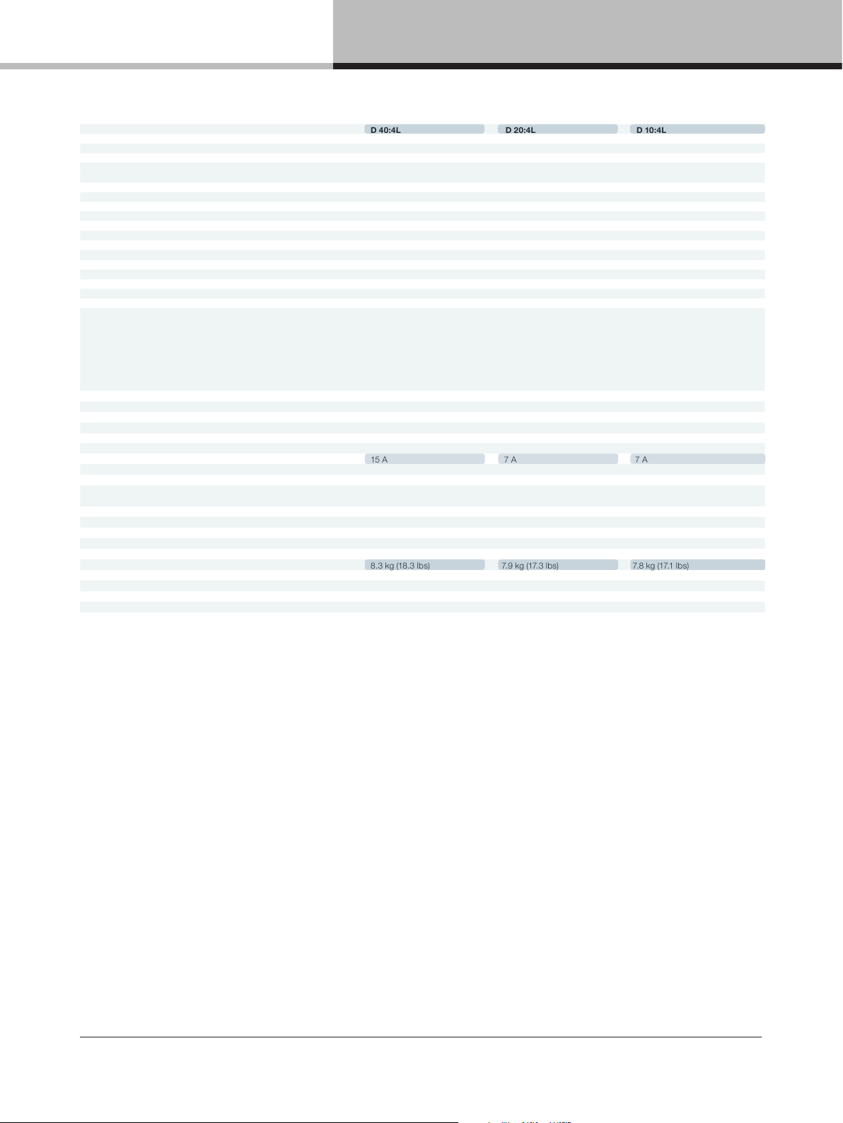
15. Technical Specifications
Back panel interface
Analog inputs 4 x Terminal block conne ctors analog input with +, - and ground
AES inputs 4 x Terminal block connectors analog input with +, - and ground
Output connectors
Ethernet ports 2 x EtherCon RJ45 Lake Controller, Dante controller and/or DLM (3rd party protocol)
Detachable mains cord Detachable locking 3-pin IEC rated at 250 V / 16 A
Front panel user interface
System status indication
Channel status indication 3 x tri-color LED per channel. Status indication separated for channel LOAD, AMP, SIGNAL status
Mute Per channel touch button for MUTE control and tri-color LED for indication
Power Touch button for ON/STANDBY control and tri-color LED for power state indication
Select Touch button and LED for bi-directional device software select functionality
Mains Power
Nominal voltage 100 - 240 V AC 50 - 60 Hz
Operating voltage 70 - 265 V AC 45 - 66 Hz
Mains wall plug Selectable on order
Power supply features
Soft start / Inrush power Ye s
Power factor correction > 0.98 for mains power > 300 W
Regulated switch mode power supply (R.SMPS) Ye s
Breaker Emulation Limiter (BEL) Yes
BEL max current threshold 15 A 7 A 7 A
Power Average Limiter (PAL) Yes
Under Voltage Limiter (UVL) Yes
Mains undervoltage and overvoltage protection and
mains glitch tolerance
Dimensions
Rack rail to rear panel W: 483 mm (19”), H: 44 mm (1 U), D: 425 mm (16.7”)
Overall depth front-rear support D: 463 mm
Weight
Finish
Approvals
D 40:4L D 20:4L D 10:4L
4 x 2 pole Terminal block connectors rated at 100 0 V / 41 A (exceeding amplier capacity) Can take up
to 8 mm2 (8.2 AWG) cables
3 x tri-color LED. FRAME, TEMP, PSU for device status indication
CEE 7/7 “Schuko” 230 V / 16 A,
NEMA 5-15 125 V / 15 A,
BS1363-A 250 V / 13 A,
IA16A3 250 V / 16 A,
AU/NZ 250 V / 10 A,
JP 125 V / 15 A,
CPCS-CCC 250 V / 10 A
Yes
8.3 kg (18.3 lbs) 7.9 kg (17.3 lbs) 7.8 kg (17.1 lbs)
Black painted steel chassis with grey painted steel front with detachable grille
CE, ETL (ANSI/UL, CSA), PSE, RCM, BIS, CCC
Note 1): Lab.gruppen burst power (1 kHz, 25 ms burst power @ 150 BPM, 12 dB Crest factor)
All specifications are subject to change without notice.
D SERIES Lake Operation Manual rev 3.0.1
52
Page 53

16. Warranty and support
16. Warranty and support
16.1. General
This product is manufactured by Lab.gruppen, and it is warranted to be free from any defects caused by
components or factory workmanship, under normal use and service, for a period of ten (10) years from date of
purchase from an authorized Lab.gruppen dealer. If the product fails to perform as specied during the warranty
period, Lab.gruppen will undertake to repair, or at its option, replace this product at no charge to its owner,
provided the unit is returned undamaged, shipping prepaid, to an authorized service facility or to the factory.
This warranty shall be null and void if the product is subjected to: repair work or alteration by a person other
than those authorized by us; mechanical damage including shipping accidents; war, civil insurrection, misuse,
abuse, operation with incorrect AC voltage; incorrect connections or accessories; operation with faulty associated
equipment; or exposure to inclement weather conditions. Damage due to normal wear and tear is not covered
by the warranty. Units on which the serial number has been removed or defaced will not be eligible for warranty
service. Lab.gruppen shall not be responsible for any incidental or consequential damages. Lab.gruppen’s
responsibility is limited to the product itself. Lab.gruppen takes no responsibility for any loss due to cancellation
of any events, or rent of replacement equipment or costs due to a third party’s or customer’s loss of prot, or any
other indirect cost or losses however incurred. Lab.gruppen reserves the right to make changes or improvements
in design or manufacturing without assuming any obligation to change or improve products previously
manufactured. This warranty is exclusive, and no other warranty is expressed or implied. This warranty does not
affect the customer’s statutory rights.
International Warranties
Please contact your supplier or distributor for this information, as rights and disclaimers may vary from country
to country.
16.2. Technical assistance and service
16.2.1. International service
If your Lab.gruppen product requires repair, contact your Lab.gruppen dealer or distributor, visit
http://labgruppen.com/support or contact Lab.gruppen by phone or email to obtain details for the nearest
authorized service center.
D SERIES Lake Operation Manual rev 3.0.1
53
Page 54

16. Warranty and support
16.2.2. Factory service
In the event a Lab.gruppen product requires factory service, you may contact Lab.gruppen’s service department
for return instructions and a Return Authorization number.
Please note for product return:
1. Use the original packing.
2. Include a copy of the sales receipt, your name, return address, phone and fax number, email address and
description of the defect.
3. Mark the Return Authorization number on the outside of the packing.
Ship the product prepaid to:
Music Group Innovation Sweden AB Faktorvägen 1
SE-434 37 Kungsbacka
Sweden
Phone: +46 300 56 28 00
service@labgruppen.com www.labgruppen.com
D SERIES Lake Operation Manual rev 3.0.1
54
Page 55

Notes
Notes
D SERIES Lake Operation Manual rev 3.0.1
55
Page 56

Notes
Notes
D SERIES Lake Operation Manual rev 3.0.1
56
Page 57

labgruppen.com
Lab.gruppen adopts a policy of continuous improvement and product specication is subject to change.
RPM, R.SMPS, PFC, CDM, BEL, UVL, CAFÉ, ESP, ISVPL, Iso–Float, Raised Cosine, MESA EQ, LimiterMax and
LoadLibrary are trademarks of Lab.gruppen AB. All other trademarks remain the property of their respective owners.
Copyright © 2017 MUSIC Group Innovation Sweden AB. All rights reserved.
Item no. OM–DSERIES–LAKE
 Loading...