

Laars Mighty Therm, Lo-Nox Installation And Operation Instructions Manual
Installation and Operation Instructions Document 2130
Installation and Operation
Instructions for
Mighty Therm
Lo-Nox
Hydronic Boilers and
Volume Water Heaters
Models PH and PW
Sizes 500-1825
These instructions are to be stored in the pocket provided on the boiler.
FOR YOUR SAFETY: This product must be installed and serviced by a professional service technician,
qualified in hot water boiler installation and maintenance. Improper installation and/or operation could
create carbon monoxide gas in flue gases which could cause serious injury, property damage, or death.
Improper installation and/or operation will void the warranty.
WARNING
If the information in this manual is not followed exactly , a fire or explosion may result
causing property damage, personal injury or loss of life.
Do not store or use gasoline or other flammable vapors and liquids in the vicinity of this or
any other appliance.
WHAT TO DO IF YOU SMELL GAS
• Do not try to light any appliance.
• Do not touch any electrical switch; do not use any phone in your building.
• Immediately call your gas supplier from a nearby phone. Follow the gas supplier's
instructions.
• If you cannot reach your gas supplier, call the fire department.
Installation and service must be performed by a qualified installer, service agency, or gas
supplier.
H0241400-

Page 2
LAARS HEATING SYSTEMS
TABLE OF CONTENTS
SECTION 1.
General Information
1.1 Introduction...................................................3
1.2 Heater Identification .....................................3
1.3 General Flow Requirement ..........................3
SECTION 2.
Installation
2.1 Heater Placement.........................................4
2.2 Installation of Indoor Heaters ....................... 4
2.2.1 Combustion Air Supply.................................4
2.2.1.a Conventional Ventilation............................... 4
2.2.1.b Forced-Air Ventilation...................................5
2.2.2 Venting .........................................................5
2.2.3 Removal of Existing Heater .......................... 6
2.3 Installation of Outdoor Heaters..................... 6
2.4 Gas Supply and Piping.................................6
2.5 Electrical Wiring............................................7
SECTION 3.
Water Piping Instruction
3.1 General Piping Practice................................ 8
3.2 Heating Boiler (PH Model)............................ 8
3.2.1 Variable Water Flow System.........................8
3.2.2 System Pressure Requirements................... 8
3.2.3 Hot/Chilled Water Systems...........................8
3.2.4 Combined Space Heating/Potable
Water Heating Systems................................ 9
3.2.5 Piping System Requirements .....................10
3.2.6 Filling the System .......................................10
3.3 Water Heater (PW Model) .......................... 10
3.3.1 Water Chemistry.........................................10
3.3.2 Piping System Requirements ..................... 11
3.3.3 Water Expansion ........................................ 11
3.3.4 Pump Requirements................................... 11
3.3.5 Water Pressure .......................................... 13
3.3.6 Tank Installation..........................................14
3.3.7 Two-Temperature .......................................14
SECTION 4.
Operating Instructions
4.1 Controls - General ...................................... 15
4.1.1 Electronic Ignition Control .......................... 15
4.1.2 Hot Surface Igniter ..................................... 15
4.1.3 Combustion Air Pressure Switch ................ 15
4.1.4 Operating Controls ..................................... 15
4.1.5 High Limit Control....................................... 15
4.1.6 Flow Switch ................................................ 16
4.1.7 Low Water Cut Off...................................... 16
4.2 Start-Up Requirements............................... 16
4.3 Normal Operating Sequence...................... 17
4.4 Hi-Limit Checkout ....................................... 17
4.5 Start-Up Procedure ....................................17
4.5.1 Lighting Instructions ...................................18
4.5.2 To Turn Off Gas to Appliance ..................... 18
4.6 Setting the Temperature Controls ............... 18
4.6.1 Hydronic Boilers .........................................18
4.6.2 Water Heaters ............................................18
SECTION 5.
Maintenance
5.1 General Instructions ................................... 18
5.2 Combustion Air Blower............................... 19
5.3 Heat Exchanger..........................................19
5.3.1 External Cleaning of Heat Exchanger ........ 19
5.3.2 Internal Cleaning of Heat Exchanger..........20
5.4 Gas and Electric Controls........................... 20
5.5 Burner Removal and Cleaning ................... 20
SECTION 6.
T roubleshooting
6.1 Sequence of Operation ..............................20
6.2 Electrical Components ...............................21
6.2.1 General Troubleshooting............................21
6.2.2 Electrical Troubleshooting .......................... 21
6.3 Mechanical Components............................ 23
6.3.1 Pressure Relief Valves Leaking
Intermittently or Steadily ............................. 23
6.3.2 Heater is Pounding, Knocking or
Emitting Steam from Relief Valves .............23
6.3.3 Soot in Flueways or in Tubes, or Noxious
Fumes Indicative of Bad Combustion......... 23
6.3.4 Water Dripping in Firebox........................... 23
SECTION 7.
Parts Descriptions and
Order Numbers
7.1 Jack and Combustion Chamber
Components ............................................... 25
7.2 Water System............................................. 25
7.3 Electrical Components ...............................26
7.4 Gas Train....................................................26
7.5 Burner Tray ................................................26
7.6 Outdoor Jacket ........................................... 33
Mighty Therm Lo-Nox
Page 3
SECTION 1.
General Information
1.1 Introduction
This manual provides information for the
installation and operation of Laars gas-fired hydronic
boilers and water heaters. It is strongly recommended
that all application and installation procedures be
reviewed completely before proceeding with the
installation. Consult the Laars factory, or local factory
representative with any problems or questions
regarding this equipment. Experience has shown that
most problems are caused by improper installation, not
system design.
Some accessory items are shipped in separate
packages. Verify receipt of all items listed on the
package slip. Inspect everything for possible damage
upon delivery, and inform the carrier of any shortages
or impairments. Any such claims should be filed with
the carrier. The carrier, not the shipper, is responsible
for shortages and damage to the shipment whether
visible or concealed.
IMPORTANT WARNING
The Laars heaters must be installed in
accordance with the procedures outlined in this
manual. The warranty does not apply to boilers not
installed or operated in accordance with these
procedures. Consult local building and safety codes
before proceeding with work. The installation must
conform to the requirements of the authority having
jurisdiction or, in the absence of such requirements, to
the latest edition of the National Fuel Gas Code; ANSI
Z223.1, National Electrical Code ANSI/NFPA 70 and/
or in Canada CAN 1 -13149 requirements.
When required by the authority having
jurisdiction, the installation must conform to
American Society of Mechanical Engineers safety
codes for controls and safety devices for automatically
fired boilers No. CSD-1, and in Canada CGA 3.3. Any
modification to the boiler, its gas controls, gas
orifices, wiring or draft diverter may void the Laars
warranty. If field conditions require such
modifications, consult factory.
1.2 Heater Identification
Consult rating plate on the boiler. The following
example simplifies the boiler identification.
1 2 3456
PH 1430 I N 21 K
(1) Basic heater model (see descriptions below).
(2) Input rate X 1000 BTU/h.
(3) Indoor (I) or Outdoor (E) installation.
(4) Gas type: Natural (N).
(5) Ignition system: (21) Hot surface (proved igniter)
ignition system.
(6) Firing modes:
On/Off (C)
2-stage (K)
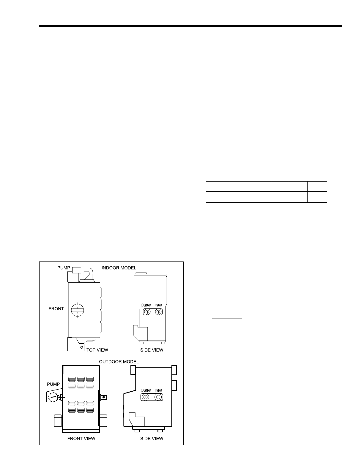
Figure 1. Boiler Configuration.
Model PH hydronic heating boilers come with
integrally mount pumps. Pumps are sized for pressure
drop through the heat exchanger only.
Model PW water heaters for use with separate
storage tank come with integrally mount pumps.
Pumps are sized for pressure drop through the heat
exchanger plus 30 feet (9.1m) of pipes and normal
fitting.
Laars heaters are available in two configurations:
an indoor version and an outdoor version. Both are
available from the factory (see Figure 1).
1.3 General Water Flow Requirement
For proper operation, all low volume hot water
heaters must have continuous flow through the heat
exchanger when firing. The system pump must be
capable of developing sufficient pressure to overcome
the resistance of the heater plus the entire circulating
system at the designed flow rate.
Page 4
LAARS HEATING SYSTEMS
SECTION 2.
Installation
2.1 Heater Placement
The heater must be placed to provide specific
clearances on all sides for maintenance and
inspections. There must also be minimum distances
maintained from combustible surfaces. These
clearances also apply to noncombustible materials
because the heater requires air circulation for proper
operation.
The heater should be mounted on a level surface.
An integral base for an installation on combustible
flooring is provided as standard equipment on all
models.
Do not install a heater on carpeting.
Under the national Fuel Gas Code, ANSI
Z223.1, it is permissible to place the heater on floors
other than noncombustible when the installation
complies with the American Insurance Code. Figures
2, 3, and 4 show common installation on combustible
flooring.
Clearance Indoor Outdoor
from in.
Top 30
Water Conn. side 12*
Pump side 6*
Front Alcove* unobstructed
Rear 8
Vent pipe** 6
Hot water pipes per code per code
* Water connection and pump side clearances of 24" (610mm)
and front clearances of 48" (1219mm) will allow easier
service access.
** One inch using type B vent (refer to Manufacturer's Instructions).
Table 1. Minimum Heater Clearances From
Adjacent Surfaces.
mm
762
305
152
203
152
in.
mm
unobstructed
24
610
24
610
24
610
- - -
2.2 Installation of Indoor Heaters
Locate the heater to provide adequate clearance
for inspection and service on all sides. See Table 1.
Install indoor heaters on a waterproof floor with
an adequate floor drain and a 6" (152mm) minimum
curb on all four sides to protect the building if heater
repairs are required. The manufacturer will not be
held liable for any water damage in connection
with this heater.
2.2.1 Combustion Air Supply
The heater location must provide sufficient air
supply for proper combustion and ventilation of the
surrounding area as outlined in the latest edition of
ANSI standard Z223.1, and any local codes that may
be applicable. Inadequate combustion air supply may
result in incomplete combustion, sooting of the heat
exchanger, and unsafe operation of the boiler.
2.2.1.a Conventional Ventilation
In the United States, these requirements specify
that small heater rooms should be provided with two
permanent air supply openings communicating
directly through the wall to outside air one within 12
inches (305mm) of the ceiling, and the other within
12 inches (305mm) of the floor. Each opening should
have a minimum free area of one square inch
(6.5 sq. cm) per 4,000 BTU/h input of the total input
rating of all appliances in the enclosed area. See Table
2 for recommended air supply for each model. An
improperly ventilated equipment room can get
excessively hot and cause accelerated deterioration
of controls and electrical components.
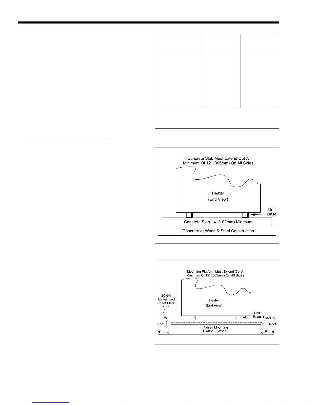
Figure 2. Typical Heater Installation on Concrete Slab.
Figure 3. Typical Heater Installation on Roof Using
Raised Platform (wood).
In Canada, Table 2 does not apply. Consult local
building codes or, in the absence of such requirements,
follow CGA requirements and/or CAN/CGA B-149
standard.
Mighty Therm Lo-Nox
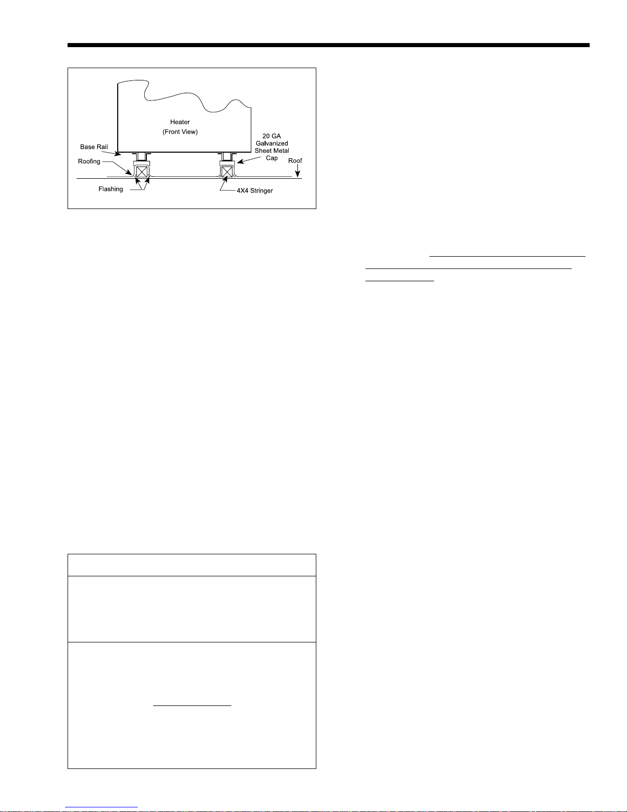
Figure 4. Typical Heater Installation on Concrete Slab.
2.2.1.b Forced-Air Ventilation
In the United States: any equipment which
exhausts air from the heater room can deplete the
combustion air supply or reverse the natural draft
action of the venting system. This could cause flue
products to accumulate in the heater room. Additional
air must be supplied to compensate for such exhaust.
The information in Table 2 is not applicable in
installations where exhaust fans or blowers of any
type are used. Such installations must be designed by
qualified engineers.
In Canada: follow Canadian standard, CAN/
CGA B-149 or local codes.
If a blower or fan is used to supply air to the
heater room, the installer should make sure it does not
create drafts which could cause nuisance shutdowns. If
a blower is necessary to provide adequate combustion
air to the heater, a suitable switch or interlock must be
wired into the heater control circuit to prevent the
heater from firing unless the blower is operating.
The heater must be completely isolated and
protected from any source of corrosive chemical fumes
such as trichlorethylene, perchloroethylene, chlorine, etc.
Heater Each Opening*
Size square inches
500 125
715 179
1010 253
1430 358
1825 457
* Net Free Area.
Check with louver manufacturers for net free area of louvers.
Correct for screen resistance to the net free area if a screen is
installed. Check all local codes applicable to combustion air.
Area indicated is for
and one at the ceiling, so the total net free area could be
double the figures indicated. For special conditions refer to the
latest edition of ANSI Z223.1.
Consult factory if openings do not communicate directly
through the walls with the outdoors.
Table 2. Minimum Recommended Air Supply to Heater.
one of two openings: one at floor level
square cm
806.5
1154.9
1632.4
2309.8
2948.6
Page 5
2.2.2 Venting
1. Laars heaters have built-in draft diverters for
natural draft operation and must not be
connected to any portion of a mechanical draft
system under positive pressure. The flue outlet
must be connected to a clear, unobstructed vent
of adequate capacity ending above the highest
point of the building with an approved vent cap.
The venting system should be installed according
to Category 1, Natural Draft per the latest edition
of ANSI Z223.1 and/or, in Canada, CAN/CGA
B-149 and any local codes having jurisdiction.
2. Do not weld or fasten the vent pipe to the boiler
drafthood. The weight of the stack must not rest
on the heater.
The drafthood and heater top must
be easily removable for normal heater service
and inspection.
IMPORTANT NOTE: Do not use sheet metal
screws at the snap lock joints of Type B gas vents.
3. Avoid using long horizontal runs of the vent
pipe, and too many 90° elbows, reductions or
restrictions. Horizontal runs should have at least
a 1/4" (6mm) rise per foot in the direction of
flow. A vent connector should be supported for
the design and weight of the material used to
maintain clearances and prevent physical damage
and separation of joints.
4. Avoid terminating heater vents near air
conditioning or air supply fans. The fans can
pick up exhausted flue products from the heater
and return them inside the building creating a
possible health hazard. A minimum of 4 feet
(1.2m) horizontal distance must be maintained
from electrical meters, gas meters, and relief
equipment.
5. Always use double-wall or insulated vent pipe
(Type B or equivalent). In cold weather,
uninsulated outside vents can chill the rising flue
products blocking the natural draft action of the
venting systems. This can create a health hazard
by spilling flue products in the heater room.
6. Avoid oversized vent piping or extremely long
runs of pipe which may cause excessive cooling
and condensation. Rule of Thumb: the total
length of the vent, including the connector and
any offset, should not exceed 15 feet (4.6m) for
every inch (25mm) of vent diameter. Longer
total lengths shown in venting tables are based
on maximum capacity, not condensation factors.
7. When the installation of a draft fan is necessary
in connecting a venting system to a Laars heater,
the installation should be engineered by
competent personnel following good engineering
practices. The draft fan supplier should be
consulted for correct size. The installation should
be in accordance with the latest edition of ANSI
Page 6
LAARS HEATING SYSTEMS
Z223.1 and/or, in Canada, CAN/CGA B-149 and
any local codes having jurisdiction. When a draft
fan is installed, a suitable draft switch must be
wired into the boiler control circuit at terminal
designated "Field Interlock" to prevent firing of
the boiler unless a positive draft has been
established.
2.2.3 Removal of Existing Heater
At the time of removal of an existing heater, the
following steps shall be followed with each appliance
remaining connected to the common venting system
placed in operation, while the other appliances
remaining connected to the common venting system
are not in operation.
1. Seal any unused openings in the common
venting system.
2. Visually inspect the venting system for proper
size and horizontal pitch and determine that
there is no blockage or restriction, leakage,
corrosion or other deficiencies which could
cause an unsafe condition.
3. Insofar as is practical, close all building doors
and windows, as well as all doors between the
space in which the appliances remaining
connected to the common venting system are
located and other spaces of the building. Turn on
clothes dryers and any appliance not connected
to the common venting system. Turn on any
exhaust fans, such as range hoods and bathroom
exhausts so they will operate at maximum speed.
Do not operate a summer exhaust fan. Close
fireplace dampers.
4. Place in operation the appliance being inspected.
Follow the lighting instructions. Adjust
thermostat so appliance will operate
continuously.
5. Test for spillage at the draft hood relief opening
(if the appliance is equipped with a drafthood),
after 5 minutes of main burner operation. Use
the flame of a match or candle, or smoke from a
cigarette, cigar or pipe.
6. After it has been determined that each appliance
remaining connected to the common venting
system properly vents when tested as outlined
above, return door, windows, exhaust fans,
fireplace dampers and any other gas-burning
appliances to their previous condition of use.
7. Any improper operation of the common venting
system should be corrected so the installation
conforms with the National Fuel Gas Code,
ANSI Z223.1. When resizing any portion of the
common venting system, the common venting
system should be resized to approach the
minimum size as determined using the
appropriate Tables in Appendix G in the
National Fuel Gas Code, ANSI Z223.1.
In Canada, at the time the boiler is removed from
common venting system, the common venting system
should be resized so the installation conforms to CAN/
CGA B149.1 or .2.
2.3 Installation of Outdoor Heaters
(Not available in Canada)
1. Locate the heater to provide the clearances as
listed in Table 1, “Minimum Heater Clearances.”
2. Do not place the heater in an enclosure or wall
recess. Avoid locations where wind deflection off
structures might cause downdraft. When such
wind conditions are possible, place the heater at
least 3 feet (0.9m) from the structures.
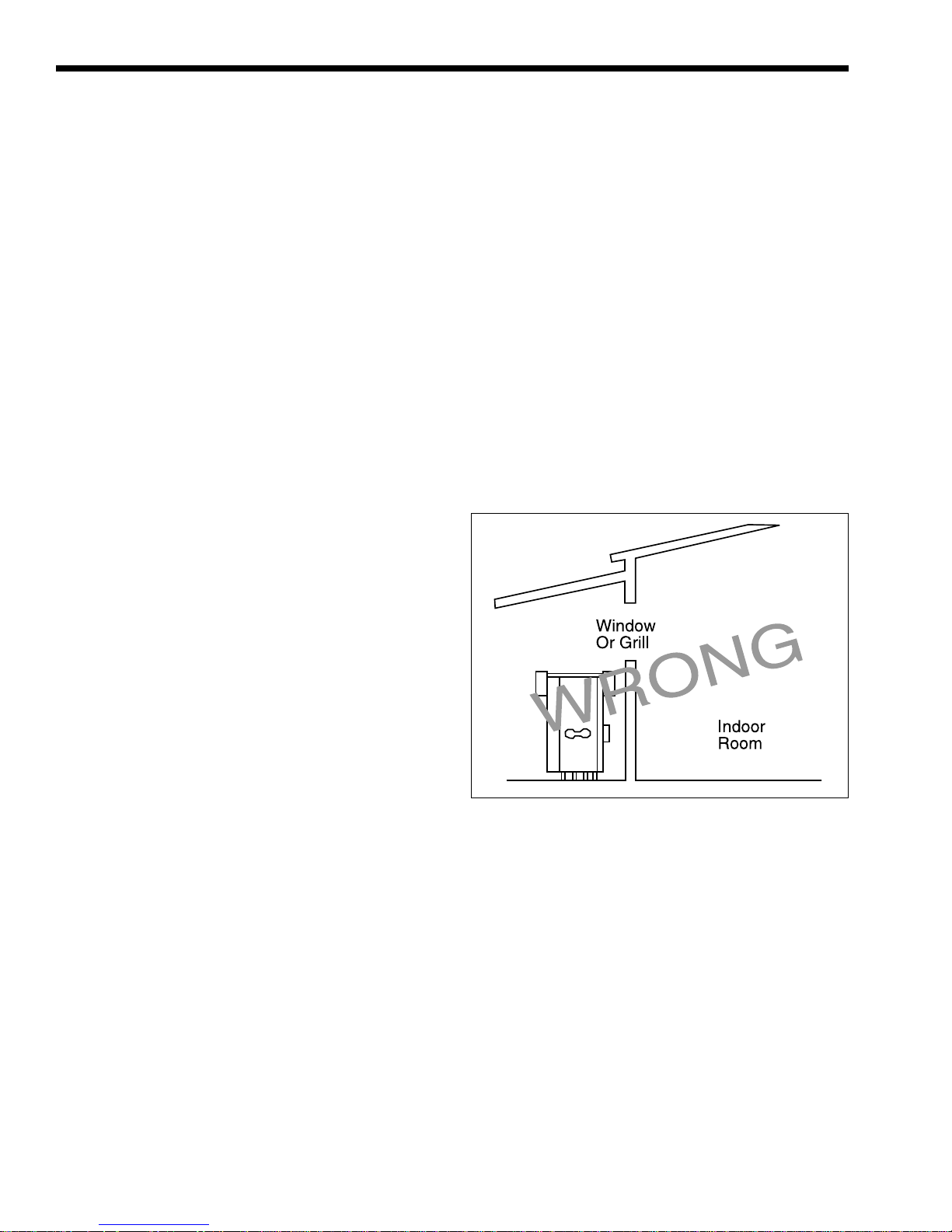
3. Never install the heater under any kind of roof
overhang. Do not place the heater below or
adjacent to any doors, windows, louvers, grills,
etc., which connect in any way with an inhabited
area of a building. This includes other structures
such as garages or utility rooms (see Figure 5).
Figure 5. Incorrect Outdoor Installation.
4. Although the Laars models are CSA designed
certified for outdoor installations, such
installations are not recommended in areas where
the danger of freezing exists unless proper
precautions are taken for freeze protection.
Outdoor installations are not recommended in
areas where the danger of snow blockage exists.
The heater should be located a safe distance from
Propane gas storage and filling equipment. Consult
local codes and fire protection authorities for advice
on specific installation restrictions.
2.4 Gas Supply and Piping
Review the following instructions before
proceeding with the installation.
1. Verify that the heater is fitted for the proper type
of gas by checking the rating plate. Laars heaters
Mighty Therm Lo-Nox
are normally equipped to operate below a
2000 foot (609.6m) altitude. Heaters equipped to
operate at higher altitudes have appropriate
stickers or tags attached, also printed information
on rating plate.
2. Use the figures in Table 3 to provide adequate
gas piping from the gas meter to the heater.
Distance from Gas Meter
or Last Stage Regulator
Size 0-100' 100-200' 200-300'
500 1½" 2" 2"
715 2" 2" 2½"
1010 2" 2½" 3"
1430 2½" 3" 3"
1825 2½" 3" 3½"
NOTE: These figures are for Natural Gas (.65 Sp. Gr.), and are
based on 1/2" water column pressure drop. Check supply
pressure with a manometer, and local code requirements for
variations. An average number of tees and elbows have been
taken into account.
Table 3. Gas Piping Sizes.
Page 7
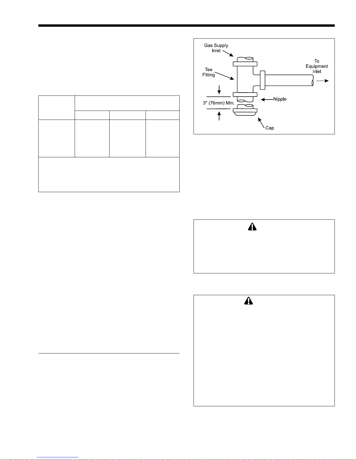
Figure 6. Sediment Trap Installation.
7. The gas manifold and control assembly is
factory tested and conforms to the safe lighting
and other performance criteria specified in the
latest editions of ANSI Z21.13 and CGA 3.3
Low Pressure Boiler Standard.
8. Before operating the heater, test the complete gas
supply system and all connections for leaks using
a soap solution. Do not use raw flame.
3. A sediment trap (drip leg) must be provided
ahead of the gas controls (see Figure 6). A
manual gas shutoff valve must also be provided
for service convenience and safety. A cap must
be provided for cleaning purposes. Check the
local codes.
4. The heater and its individual shutoff valve must
be disconnected from the gas supply piping
system during any pressure testing of that system
at test pressures in excess of 1/2 psig. The heater
must be isolated from the gas supply piping
system by closing its individual manual gas
shutoff valve during any pressure testing of the
piping system at test pressures equal to or less
than 1/2 psig.
5. Provide gas supply pressure to the heater as
follows:
Natural
Gas
Max. (inches water column) 10
Min. (inches water column) 6.5
NOTE: the heater and all other gas appliances sharing
the boiler gas supply line must be firing at maximum
capacity to properly measure the inlet supply pressure.
Low gas pressure could be an indication of an
undersized gas meter and /or obstructed gas supply
line.
6. The correct burner manifold gas pressure is
stamped on the rating plate. The regulator is
preset at the factory and normally requires no
further adjustment.
Caution
Since some leak test solutions (including soap
and water) may cause corrosion or stress
cracking, the piping must be rinsed with water
after testing, unless it has been determined
that the leak test solution is noncorrosive.
2.5 Electrical Wiring
WARNING
The heater must be electrically grounded in
accordance with the most recent edition of the
National Electrical Code, ANSI/NFPA 70. In
Canada, all electrical wiring to the boiler should
be in accordance with the latest edition of CSA
C22.1 Canadian Electrical Code, Part 1. Do not
rely on the gas or water piping to ground the
metal parts of the boiler. Plastic pipe or
dielectric unions often isolate the heater
electrically. Service and maintenance
personnel who work on or around the heater
may be standing on wet floors and could be
electrocuted by an ungrounded heater.
Wiring diagrams are included in the information
packet provided with each unit.
1. All Laars heaters need 115V 60Hz supply
voltage unless specifically ordered otherwise.
Page 8
Check heater wiring and pump for correct
voltage, frequency and phase. Consult the
National Electrical Code or the Canadian
Electrical Code regarding branch circuit
requirements for equipment with these motors.
2. The heater should be wired exactly as shown in
the wiring diagram.
3. All field installed electrical safety devices and all
field installed controllers (valve end switches,
draft switches, relays, timers) can be connected
to the heater control to the terminals shown in
the wiring diagram designated “Field Interlock.”
4. Where the heater is installed with a draft fan
refer to the fan manufacturer's wiring diagram.
The draft switch should be wired across the field
interlock terminals in the heater control panel.
LAARS HEATING SYSTEMS
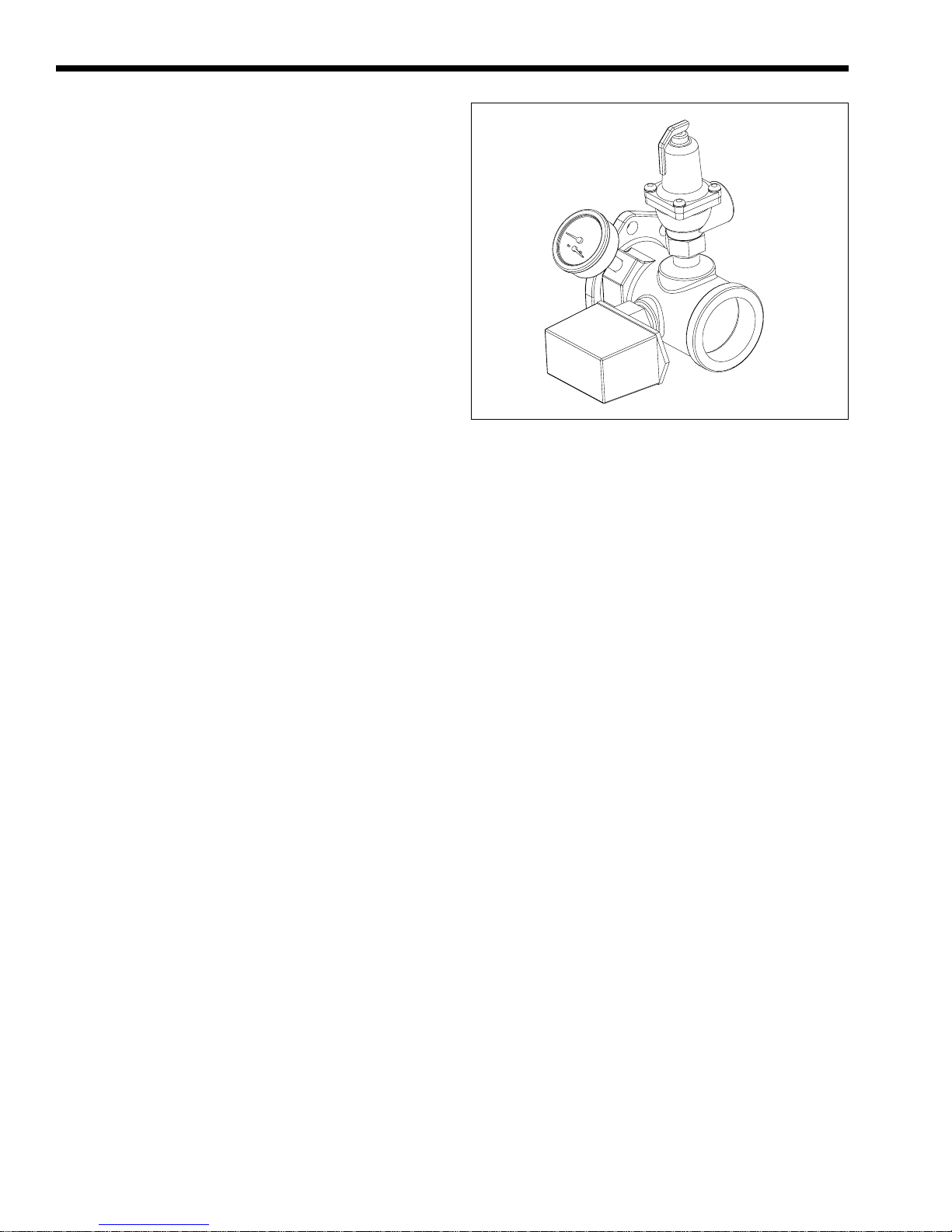
Figure 7. Pressure Relief Valve Location.
SECTION 3.
Water Piping Instruction
3.1 General Piping Practice
1. Be sure to provide valves at the inlet and outlet
of the heater so it can be readily isolated for
service. A butterfly, ball type or similar type of
valve is recommended.
2. The pressure relief valve installed in the tapped
opening provided in the outlet header (see Figure
7), must be piped, but not fastened, to a drain or
floor sink. The drain pipe must be the same size
as the valve outlet and must pitch downward
from the valve. Pay special attention to relief
valve settings in installations where the heater is
located on the ground floor of a tall building, or
where the operating temperature of the heater is
above 210°F (99°C). In both instances, the static
pressure of the system is elevated and could
cause the relief valve to leak and bring
considerable raw water into the system.
3. Where no special setting of the relief valve is
ordered, the factory will furnish a 75 psi setting
for heating boilers (PH models), and 125 psi for
water heaters (PW models).
4. The pressure relief valve lever must be tripped at
least once a year to insure that waterways are
clean. When manually operating lever, water will
discharge through the drain line. Precautions
must be taken to avoid contact with hot water
and water damage.
3.2 Heating Boiler (PH Model)
3.2.1 Variable Water Flow System
Heating systems using zone valves, zone pumps
or 3-way valves can experience reduced water flow
through the boiler. This can result in an excessive
water temperature rise and unstable boiler operation. If
the system water flow is variable, the boiler's
temperature sensor must be installed in the outlet
water. Laars recommends primary-secondary pumping
for all variable flow systems (see Figure 9). Primarysecondary pumping is mandatory for variable flow
systems. The boiler pump in a primary-secondary
system maintains constant flow through the boiler
even though the system flow is variable. In a primarysecondary system the pressure drop of the boiler is not
added to the system.
3.2.2 System Pressure Requirements
The boilers are designed to operate on closed,
pressurized systems. Maintain a minimum of 12 psi
(81.8 kPa) on the system where boiler supply water
temperature is 200°F (93°C) or less. If higher
temperatures are required, the minimum system
pressure should be at least 15 psi (102.2 kPa) above
the water vapor pressure corresponding to the elevated
water temperature.
Heating boilers are not suitable for open systems
unless the supply water temperatures are kept below
180°F (82°C), and a minimum of 5 psi (34.1 kPa)
static head is maintained at the boiler.
3.2.3 Hot/Chilled Water Systems
When a boiler is connected to an air conditioning
system where the same water is used for heating and
cooling, you must prevent chilled water from entering
the boiler When changing such a system from cooling
to heating, allow the chilled water to circulate through
the building, after the chiller has been turned off, for a
period long enough for the water to warm up to at
least 105°F (41°C) before the water flows into the
boiler. It is equally important to prevent hot water
from entering the chiller. The system shown in
Mighty Therm Lo-Nox
Page 9
Figure 8 is suggested to make sure the system water is
neither too hot nor too cold when a changeover takes
place. When a boiler is connected to heating coils
located in air handling units (where they may be
exposed to refrigerated air circulation), install a flow
Suggested Wiring Diagram For
T empering System Water at
Changeover From Heating To Cooling
DPDT Manual or Automatic
Change-Over Switch
DPDT - Set at Change-Over
Temperature
115/24V
Transformer
From
Chiller
3-Way Valve No. 1
Change-Over
(Heating and Cooling)
Valve Motors
2-Pos
3-Wire - 24V
From
Boiler
3-Way Valve No. 2
To By-Pass
Both Heater and
Chiller
Figure 8. Boiler-Chiller Installation.
Clock Timer
Auto-Resetting
Set at 15 Minute SPDT
To Boiler
and
Chiller
By-Pass
From
System
To
System
control valve or other automatic means to prevent
gravity circulation of chilled water through the boiler.
Chilled water in the boiler will create condensate on
the boiler tubes. Boilers installed in violation of the
foregoing may void the warranty.
3.2.4 Combined Space Heating/Potable
Water Heating Systems
When using the Laars boiler as a source of heat
for a combined space heating/potable water heating
system, be sure to follow the instructions of the space
heating system.
Do not use water piping, fittings, valves, pumps,
and any other components which are not compatible
with potable water.
Do not connect the heater, which will be used to
supply potable water, to any heating system or
components previously used with a nonpotable water
heating system.
Do not add boiler treatment or any chemicals to
the heating system piping, since the piping contains
water for potable use.
Do not use solder containing lead in the potable
water lines.
Some jurisdictions may require a backflow
preventer in the cold water line. In such cases,
pressure relief valve may discharge water due to
expansion. An expansion tank approved for potable
water will eliminate this condition. Follow the
manufacturer's instructions for installation of the
expansion tank.
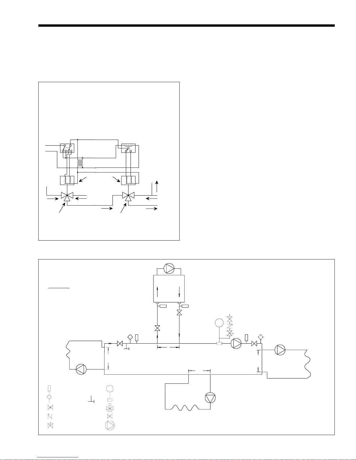
WARNING: This drawing shows suggested
piping configuration and valving. Check with
local codes and ordinances for additional
requirements.
12"
Max.
LEGEND:
Thermometer
Temperature
Sensor
Globe Valve
Check Valve
Pressure Reducing Valve
w/Fast Fill Bypass
Purge
Valve
Expansion Tank
with Air Scoop and
Auto Air Vent
3-Way Valve
Valve
Pump
12"
Max.
Boiler Circulation
Pump
12"
Max.
Cold Water
Make-Up
System Pump
12"
Max.
Boiler circuit piping must be equal to or larger
than boiler water connection size.
Boiler circulation pump sized for flow through
boiler.
Dotted devices indicate alternate locations.
Figure 9. Primary-Secondary Plumbing.

Page 10
LAARS HEATING SYSTEMS
3.2.5 Piping System Requirements
1. Provide a boiler installed above radiation level
with a low water cutoff device either as part of
the boiler or at the time of boiler installation.
2. Install manual and/or automatic bleeding devices
at high points in the system to eliminate air.
Install a correctly sized expansion or
compression tank with suitable air charger and
tank drainer, as appropriate.
3. Support the weight of all water and gas piping by
suitable hangers or floor stands.
4. Check piping diagrams with local applicable
plumbing, heating and building safety codes.
3.2.6 Filling The System
1. Ensure the system is fully connected. Close all
bleeding devices and open make-up water valve.
Allow system to fill slowly.
2. If make-up water pump is employed, adjust
pressure switch on pumping system to provide a
minimum of 12 psi (81.8 kPa) at the highest
point in the heating loop.
3. If a water pressure regulator is provided on the
make-up water line, adjust the pressure regulator
to provide at least 12 psi (81.8 kPa) at the
highest point in the heating loop.
4. Open bleeding devices on all radiation units at
the high points in the piping throughout the
system, unless automatic air bleeders are
provided at such points.
5. Run system circulating pump and boiler pump
for a minimum of 30 minutes with the boiler gas
shut off.
6. Open all strainers in the circulating system,
check flow switch operation, and check for
debris.
7. Recheck all air bleeders as described in Step 4
above.
8. Check liquid level in expansion tank. With the
system full of water and under normal operating
pressure, the level of water in the expansion tank
should not exceed 1/4 of the total, with the
balance filled with air.
9. Start up boiler according to procedure described
in Section 4. Operate the entire system, including
the pump, boiler, and radiation units for one (1)
hour.
10. Recheck the water level in the expansion tank. If
the water level exceeds 1/4 of the volume of the
expansion tank, open the tank drainer and drain
to that level.
11. Shut down the entire system and vent all
radiation units and high points in the system
piping as described in Step 4 above.
12. Close make-up water valve and check strainer in
pressure reducing valve for sediment or debris
from the make-up water line. Reopen make-up
water valve.
13. Check gauge for correct water pressure and also
check water level in system. If the height
indicated above the boiler insures that water is at
the highest point in the circulating loop, then the
system is ready for operation.
14. Within three (3) days of start-up, recheck all air
bleeders and expansion tank as described in
Steps 4 and 8 above.
3.3 Water Heater (PW Model)
3.3.1 Water Chemistry
Laars equipment is designed for use in a wide
variety of water conditions. The water velocity
maintained in the heat exchanger tubes is kept high
enough to prevent scaling from hard water and low
enough to avoid corrosion from soft water. Ninetyfive percent of the urban areas in the country have
water that is compatible with this equipment, but in
some areas a water supply will contain a large quantity
of scaling chemicals or the water may be extremely
soft and corrosive. In rare situations the water will
contain both scaling chemicals and corrosive
chemicals such as calcium or sodium chloride. These
conditions may be the result of a nearby well or
pumping station and the particular condition may not
be characteristic of the entire city water system.
If an installer observes damage from these
conditions to any water handling equipment in the
area, a factory representative should be contacted
immediately for assistance in minimizing maintenance
costs. If erosion is present, the pump impeller can be
replaced to reduce water velocity. If scaling conditions
are bad, tube cleaning maintenance schedules can be
established to prevent tube burn-out and cracking.
Neglecting the problem could mean serious damage to
the heater and water system.
Scaling can be recognized as a layer deposited
on the inner walls of the tube which reduces the inner
diameter of the tube. Scale can be any color or texture;
smooth or rough, granular or amorphous. Signs of
erosion are generally pitting, cavitation, ridges and
“islands” on the inner walls of the tubes. Since this
condition results from extremely soft water sources, or
as a result of a water softening program, the internal
copper surfaces will be extremely shiny. Other
chemicals, such as chlorine or chlorides in the water,
will cause dark surfaces of erosion.
In areas where the water supply is extremely
corrosive, it is advisable to order the heater with
cupro-nickel tubes in the exchanger.
Damage From Scaling, Corrosion, or Erosion
is Not Covered by the Warranty.
Mighty Therm Lo-Nox
3.3.2 Piping System Requirements
1. Check piping diagrams with local applicable
plumbing, heating and building safety codes.
2. All two-temperature systems using temperature
valves must have forced recirculation in the low
temperature building loop.
3. A check valve installed at the hot water inlet to
the tempering valve will prevent cold water from
being drawn in reverse through the tempering
valve into the hot water.
4. When installing a tempering valve, place at
bottom of antithermosyphon loop at least 24"
high to prevent excessive hot water from
entering mixed water supply. Bring the cold
water supply up from the floor to the valve (see
Figure 10).
Page 11
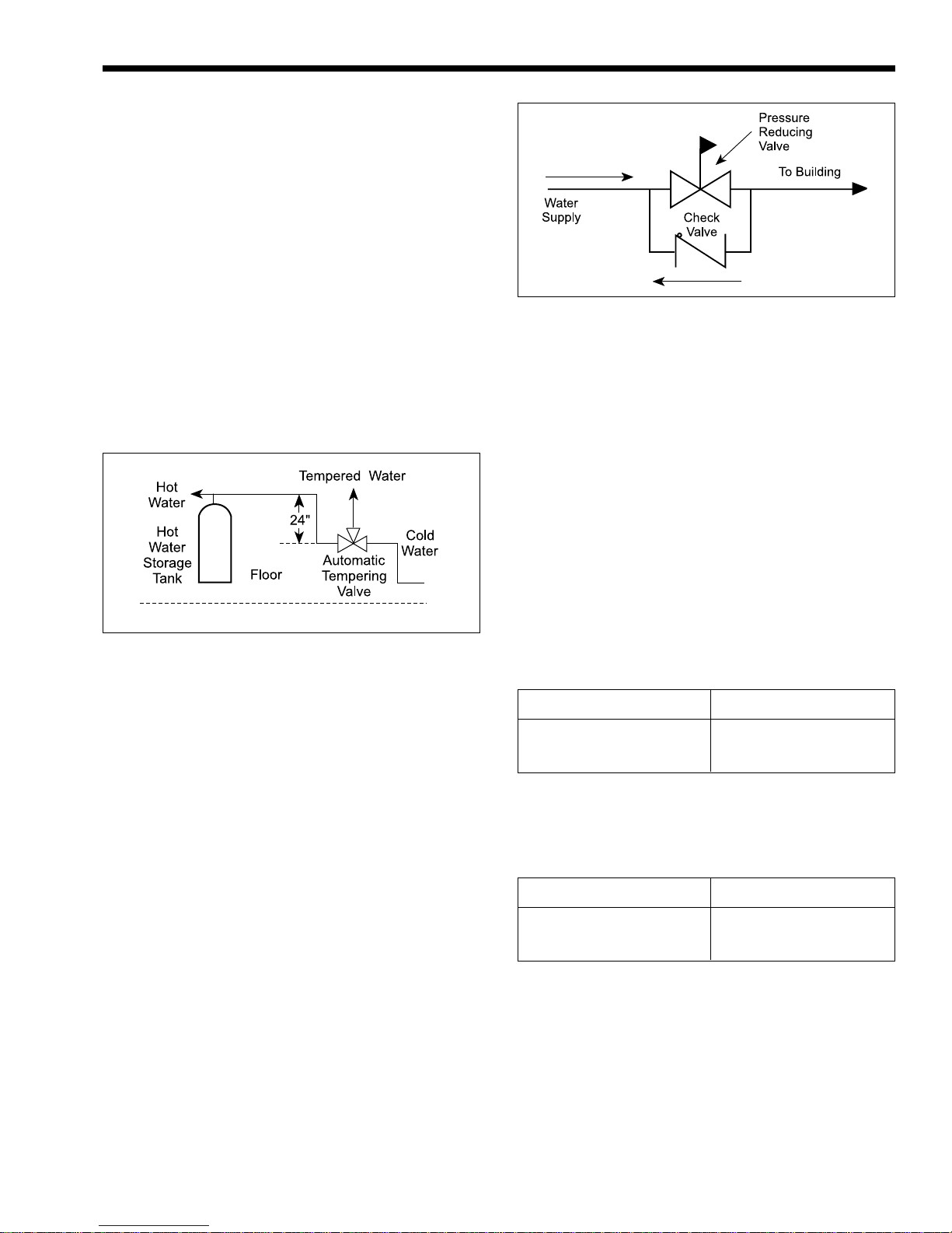
Figure 11. Check Valve/Pressure Reducing Valve
Installation.
3. Install an auxiliary small relief valve set at 25 psi
less than the main relief valve. The valve must be
piped to a drain and may require occasional
cleaning. It will bleed off the expanded water
and protect the main pressure relief valve from
becoming fouled.
4. Install a properly sized expansion tank.
Figure 10. Tempering Valve Installation.
3.3.3 Water Expansion
When cold water is heated the water expands. If
no water is being used during the heat-up period the
expanded water will normally back up into the city
mains.
A water pressure reducing valve installed in the
incoming cold water line may act as a check valve and
prevent the expanded water from moving backward.
This will cause pressure to rise in the heater, which
will be relieved by the pressure relief valve.
If the relief valve pops frequently a mineral
deposit may build up on the valve seat, causing it to
leak.
The following suggestions may solve the
problem:
1. Replace the installed water pressure reducing
valve with a suitable valve having a back flow
port. These valves have a back flow port which
allows water to flow backwards when the
pressure in the system exceeds the pressure in the
mains.
2. Install a check valve around the pressure
reducing valve to permit reverse flow. This will
allow the expanded water to back flow into the
mains (see Figure 11).
3.3.4 Pump Requirements
1. The factory provided pump on PW heaters are
sized to provide proper circulation through the
heater and heater-to-tank circulation loop (see
Figures 12, 13 and 14). If the heater-to-tank
circulation loop does not contain more than 6
elbows and 30 feet of pipe, use pipe fittings in
the loop no smaller than the following:
Model Pipe Size
500 through 715 2"
1010 through 1825 2-1/2"
If the heater-to-tank circulating loop contains
more than 6 elbows and 30 feet of pipe, use
pipe or fittings in the loop no smaller than the
following:
Model Pipe Size
500 through 715 2-1/2"
1010 through 1825 3"
2. Model PW heater is not suitable for heating
swimming pools or any other application where
temperature of the water flowing through the
heater remains below the dew point (110°F).
In applications requiring the rapid use of
measured volumes of water, the recovery of the
heater between the time intervals of use must
equal the volume used. See the recovery table in
the current Document 2129 (Submittal Data).
3. Pump Sizing: the heater circulating pump is
sized to provide enough flow to prevent damage
 Loading...