

Laars Mascot II, LMC, Mascot II LMC, Mascot II LMH Installation And Operation Instructions Manual
Installation and Operation Instructions Document 1230A
Installation and Operation
Instructions for
Mascot® II
Modulating Boiler
Model LMH
125 MBTU/h
Combination
Boiler and Water Heater
Model LMC
125 MBTU/h
FOR YOUR SAFETY: This product must be installed and serviced by a professional service technician,
qualified in hot water boiler and heater installation and maintenance. Improper installation and/or operation
could create carbon monoxide gas in flue gases which could cause serious injury, property damage, or
death. Improper installation and/or operation will void the warranty.
WARNING
If the information in this manual is not
followed exactly, a fire or explosion may
result causing property damage, personal
injury or loss of life.
Do not store or use gasoline or other
flammable vapors and liquids in the vicinity
of this or any other appliance.
WHAT TO DO IF YOU SMELL GAS
• Do not try to light any appliance.
• Do not touch any electrical switch; do not
use any phone in your building.
• Immediately call your gas supplier from a
nearby phone. Follow the gas supplier's
instructions.
• If you cannot reach your gas supplier, call
the fire department.
Installation and service must be performed by
a qualified installer, service agency, or gas
supplier.
Assurez-vous de bien suivres les instructions
données dans cette notice pour réduire au
minimum le risque d’incendie ou d’explosion ou
pour éviter tout dommage matériel, toute
blessure ou la mort.
Ne pas entreposer ni utiliser d’essence ni
d’autres vapeurs ou liquides inflammables dans
le voisinage de cet appareil ou de tout autre
appareil.
QUE FAIRE SI VOUS SENTEZ UNE ODEUR DE GAZ:
• Ne pas tenter d’allumer d’appareils.
• Ne touchez à aucun interrupteur. Ne pas vous
servir des téléphones dansle bâtiment où vous
vous trouvez.
• Appelez immédiatement votre fournisseur de
gaz depuis un voisin. Suivez les instructions
du fournisseur.
• Si vous ne pouvez rejoindre le fournisseur de
gaz, appelez le sservice des incendies.
L’installation et l’entretien doivent être assurés par
un installateur ou un service d’entretien qualifié ou
par le fournisseur de gaz.
AVERTISSEMENT
H2338100A

Page 2
LAARS Heating Systems
TABLE OF CONTENTS
SECTION 1.
General Information
1.1 Introduction........................................................ 4
Model Nomenclature ......................................... 4
1.2 Model Identification............................................ 4
1.3 Appliance Overview........................................... 4
1.4 Warranty............................................................ 4
1.5 Unpacking ......................................................... 5
1.6 Dimensions........................................................ 5
SECTION 2.
Locating the Appliance
2.1 Locating the Appliance ...................................... 8
2.2 Locating Appliance for Correct Vent Distance
from Outside Wall or Roof Termination.............. 8
SECTION 3.
Venting and Combustion Air
3.1 Combustion Air ................................................ 10
3.1.1 Combustion Air from Room ............................. 10
3.1.2 Ducted Combustion Air.................................... 10
3.2 Venting (Exhaust) ............................................ 11
3.3.1 Side Wall Vent T erminal................................... 12
3.3.2 Side Wall Combustion Air Terminal.................. 12
3.3.3 Vertical Vent Terminal ...................................... 12
3.3.4 Vertical Combustion Air Terminal..................... 12
3.3.5 Installations in the Commonwealth
of Massachusetts............................................. 14
3.4 Common Vent Test .......................................... 14
SECTION 4.
Gas Supply and Piping
4.1 Gas Supply and Piping......................................... 16
SECTION 5.
Pump Capacity
5.1 Mascot II Heating System Pump Capacity ........... 17
SECTION 6.
Water Connections
6.1 Central Heat System Piping ............................ 17
6.2 Cold Water Make-Up....................................... 17
6.3 Freeze Protection ............................................ 18
6.4 Suggested Piping Schematics......................... 19
6.5 Recognized Chemicals.................................... 19
6.6 Domestic Hot Water (DHW) Piping (LMC)....... 19
SECTION 7.
Electrical Connections
7.1 Main Power...................................................... 25
7.2 Pump Connections .......................................... 25
7.3 24Vac Transformer Circuit Breaker.................. 25
7.4 Central Heat - Call for Heat ............................. 25
7.5 Outdoor Air Temperature Sensor..................... 25
7.6 Domestic Hot Water Connection ..................... 25
7.7 System Sensor
(lead lag/cascading operation only)................. 25
7.8 External Control Connections.......................... 25
7.9 Lead Lag / Cascading Wiring Connections ..... 25
7.10 Wiring Diagrams .............................................. 26
SECTION 8.
Control Setup and Operation
8.1 Display Navigation........................................... 28
8.2 Ignition Control - Sequence of Events ............. 28
8.3 Modulation Control .......................................... 29
8.4 Pump Control................................................... 29
8.5 High Limit......................................................... 29
8.6 Stack Temperature........................................... 29
8.7 Domestic Hot Water Temperature ................... 29
8.8 Lead Lag / Cascading...................................... 29
8.8.1 Lead Lag Setpoint ........................................... 29
8.8.2 Lead Lag Master / Slave Selection .................. 29
8.8.3 Lead Lag Address ........................................... 29
8.8.4 Lead Lag Hysteresis........................................ 29
8.8.5 Lead Lag Base Load Setting ........................... 29

Mascot II Boilers and Water Heaters
Page 3
SECTION 9.
Modes of Operation
9.1 Hydronic Heating Demand .............................. 30
9.2 Hydronic Heating with Outdoor Reset ............. 30
9.3 Hydronic Heating Using External
Modulation Control .......................................... 30
9.4 Hydronic Heating Using Local Lead-Lag/
Cascading Feature .......................................... 31
9.5 Warm Weather Shutdown................................ 31
9.6 Domestic Hot Water Demand (LMC only) ....... 31
SECTION 10.
Operating Instructions
10.1 Filling the Boiler System .................................. 32
10.2 Operating the Burner and Set Up .................... 32
10.2.1Burner Operation ............................................. 32
10.2.2Boiler Setup and Adjustment ........................... 33
10.3 Shutting Down Mascot II.................................. 33
10.4 To Restart Mascot II......................................... 33
12.1 Sequence of Operation.................................... 37
12.2 Short Cycling ................................................... 37
12.3 Error Codes ..................................................... 37
SECTION 13
Replacement Parts
13.1 General Information......................................... 40
13.2 Parts List.......................................................... 40
SECTION 11.
Maintenance
11.1 System Maintenance ....................................... 35
11.2 Appliance Maintenance and Component
Description ...................................................... 35
11.2.1Burner.............................................................. 35
11.2.2Appliance Control ............................................ 35
11.2.3Ignitor Assembly .............................................. 35
11.2.4Flame Sensor .................................................. 36
11.2.5Blower ............................................................. 36
11.2.6Heat Exchanger Coils ...................................... 36
11.2.7Gas Conversion............................................... 36
SECTION 12.
T rouble Shooting
Page 4
LAARS Heating Systems
SECTION 1.
General Information
WARNING
Mascot II units must be installed in accordance with
the procedures detailed in this manual, or the LAARS
Heating Systems warranty will be voided. The
installation must conform to the requirements of the
local jurisdiction having authority, and, in the United
States, to the latest edition of the National Fuel Gas
Code, ANSI Z223.1/NFPA54. In Canada, the
installation must conform to the latest edition of CSA
B149.1 Natural Gas and Propane Gas Installation
Code, and/or local codes. Where required by the
authority having jurisdiction, the installation of Mascot
II boilers must conform to the Standard for Controls
and Safety Devices for Automatically Fired Boilers,
ANSI/ASME CSD-1. Any modifications to the boiler,
its gas controls, or wiring may void the warranty. If
field conditions require modifications, consult the
factory representative before initiating such
modifications.
1.1 Introduction
This manual provides information necessary for
the installation, operation, and maintenance of LAARS
Heating Systems Mascot II appliances. Read it carefully
before installation.
All application and installation procedures should
be reviewed completely before proceeding with the
installation. Consult the LAARS Heating Systems
factory, or local factory representative, with any
problems or questions regarding this equipment.
Experience has shown that most operating problems are
caused by improper installation.
Mascot II is protected against over pressurization.
A pressure relief valve is included with each Mascot II.
The PRV should be installed prior to filling the system.
Refer to Figures 1 and 2 for PRV locations.
IMPORTANT: The inlet gas pressure to the appliance
must not exceed 13" W.C. (3.2kPa).
All installations must be made in accordance with
1) American National Standard Z223.1/NFPA54-Latest
Edition “National Fuel Gas Code” or 2) CSA B149.1
“Natural Gas and Propane Installation Code” and with
the requirement of the local utility or other authorities
having jurisdiction. Such applicable requirements take
precedence over the general instructions contained herein.
All electrical wiring is to be done in accordance
with the local codes, or in the absence of local codes,
with: 1) The National Electrical Code ANSI/NFPA No.
70-latest Edition, or 2) CSA STD. C22.1 “Canadian
Electrical Code - Part 1”. This appliance must be
electrically grounded in accordance with these codes.
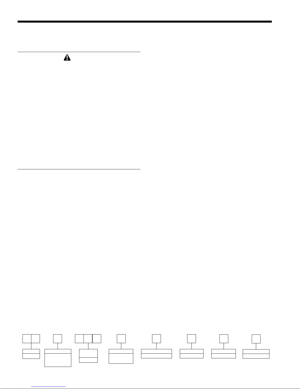
1.2 Model Identification
Consult the rating plate on the unit. The following
information describes the model number structure.
(1-2) Model Series Designation
L M = Mascot II
(3) Usage
H = Modulating Boiler
C = Combination Boiler and Water Heater
(4-6) Size
1 2 5 = 125,000 BTU/hr input
(7) Fuel
N = Natural Gas
P = LP Gas
(8) Altitude
A = 0-10,000 Feet
(9) Revision
1 = First version
(10) Options Code
X = No Options
(11) Pump Options
X = Std Pump
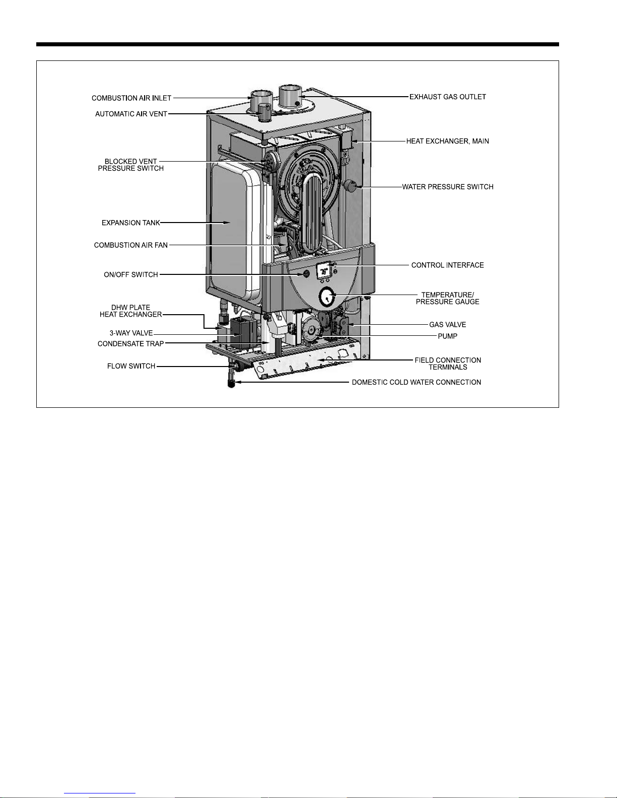
1.3 Appliance Overview
See Figure 2.
1.4 Warranty
LAARS Heating Systems’ Mascot II appliances
are covered by a limited warranty. The owner should
complete the warranty registration at www.Laars.com.
All warranty claims must be made to an authorized
LAARS Heating Systems representative. Claims must
123456 7 8 9 10 11
LM 125 A 1 X X
SERIES
L M
USAGE
H - HYDRONIC
C - COMBI
UNIT
SIZE
MBTU/h
1 2 5
Model Nomenclature
FUEL
N - NATURAL
P - PROPANE
ALTITUDE
A - 0-10,000 FEET
REVISION
1 - FIRST
OPTIONS
X - NONE
PUMP
X - STANDARD
Mascot II Boilers and Water Heaters
include the serial number and model (this information
can be found on the rating plate), installation date, and
name of the installer. Shipping costs are not included in
the warranty coverage.
Some accessory items may be shipped in separate
packages. Verify receipt of all packages listed on the
packing slip. Inspect everything for damage
immediately upon delivery, and advise the carrier of any
shortages or damage. Any such claims should be filed
with the carrier. The carrier, not the shipper, is
responsible for shortages and damage to the
shipment whether visible or concealed.
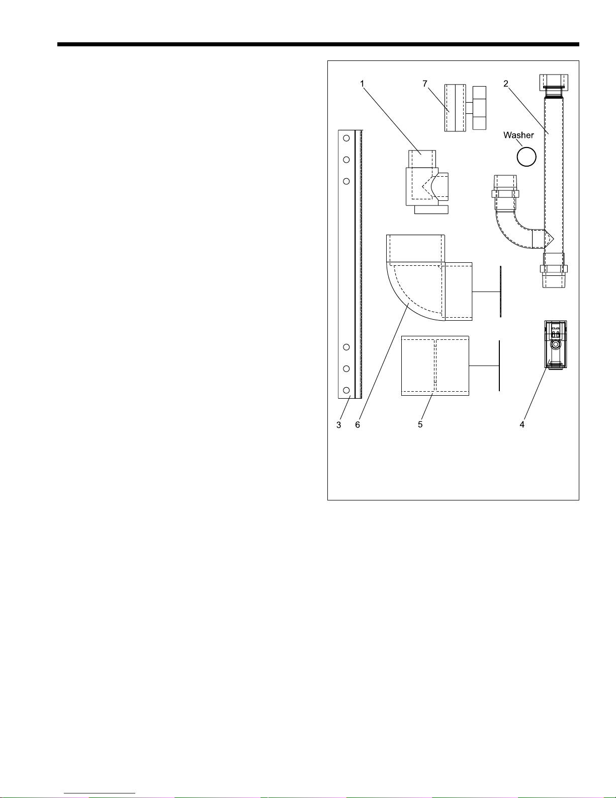
1.5 Unpacking
The Mascot II is shipped in a single crate with the
following standard components packed with the
appliance (see Figure 1):
2" PVC Terminal Kit (tee, elbow, screens, PRV
adapter and 30psi PRV flow restrictor), wall
mounting bracket (bolts/mounting hardware
provided by installer).
Page 5
1. Remove all packing and tie-down materials.
2. Check contents of the carton against items shown.
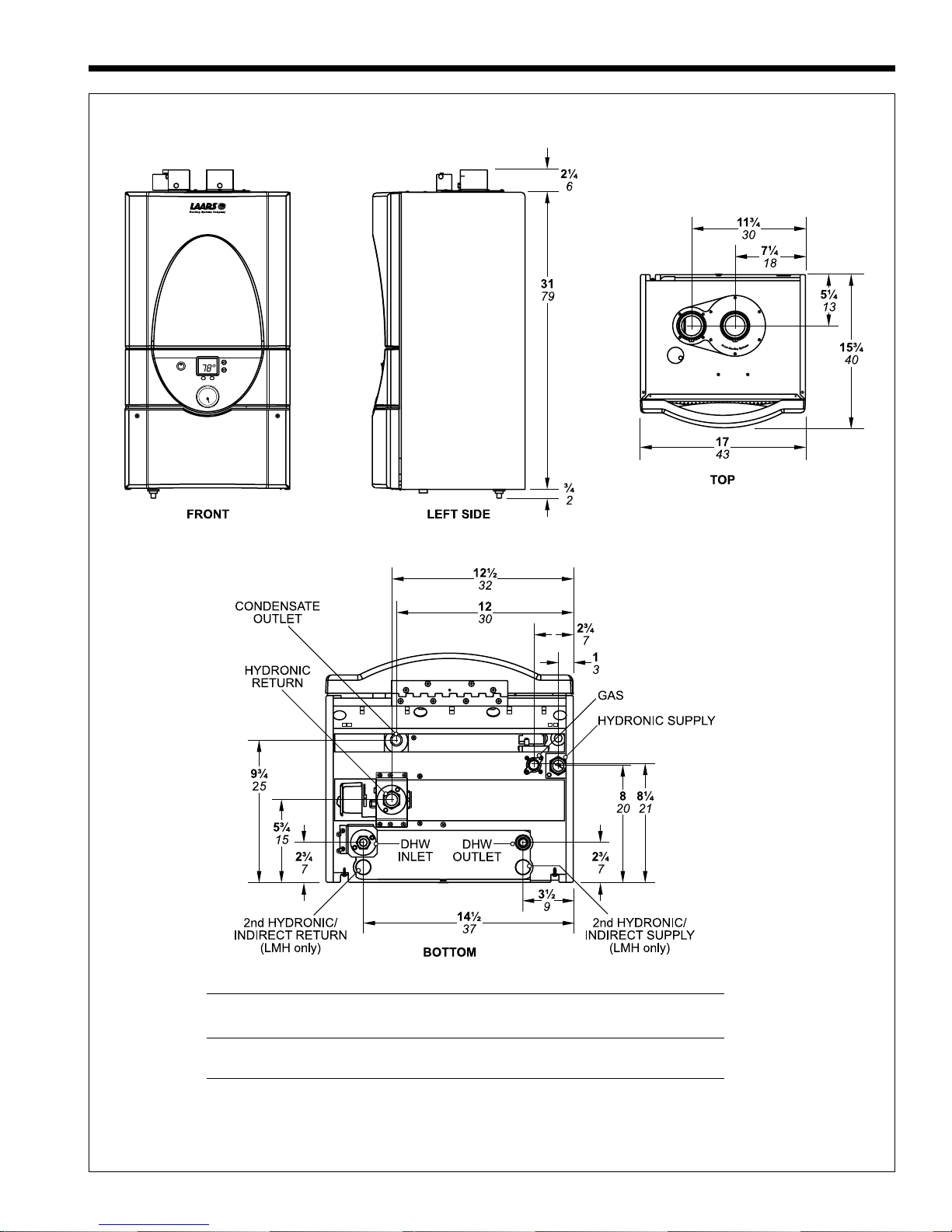
1.6 Dimensions
Dimensions are shown in Figure 3.
1) PRV, 30 PSI 5) Exhaust terminal assy
2) PRV Pipe w/ washer 6) Air intake terminal assy
3) Wall attach bracket 7) Ball valve
4) Outdoor sensor 8) System sensor
9) Flow restrictor (not shown)
Figure 1. Contents of Shipping Package.
(not shown)
Page 6
LAARS Heating Systems
Figure 2. Location of Components.
Mascot II Boilers and Water Heaters
Page 7
Cond. Hydronic DHW 2nd Gas Hydronic DHW 2nd
Outlet Return Inlet Return Supply Supply Outlet Supply
3/4" 3/4" 1/2" 3/4" 1/2" 3/4" 1/2" 3/4"
PVC copper NPT copper NPT NPT NPT copper
Figure 3. Dimensional Drawing.
Page 8
LAARS Heating Systems
SECTION 2.
Locating the Appliance
2.1 Locating the Appliance
Mascot II is for indoor installations only.
The appliance should be located to provide
clearances on all sides for maintenance and inspection.
It should not be located in an area where leakage of any
connections will result in damage to the area adjacent to
the appliance or to lower floors of the structure.
When such a location is not available, it is
recommended that a suitable drain pan, adequately
drained, be installed under the appliance.
The appliance is design certified by CSAInternational for installation in basements; in closets,
utility rooms or alcoves. Mascot II Boilers must never
be installed on carpeting. The location for the
appliance should be chosen with regard to the vent pipe
lengths and external plumbing and on a level surface.
The unit shall be installed such that the gas ignition
system components are protected from water (dripping,
spraying, rain, etc.) during operation and service
(circulator replacement, control replacement, etc.).
When vented vertically, the Mascot II must be located
as close as practical to the vertical section of the vent. If
the vent terminal and/or combustion air terminal
terminate through a wall, and there is potential for snow
accumulation in the local area, both terminals should be
installed at an appropriate level above grade or the
maximum expected snow line.
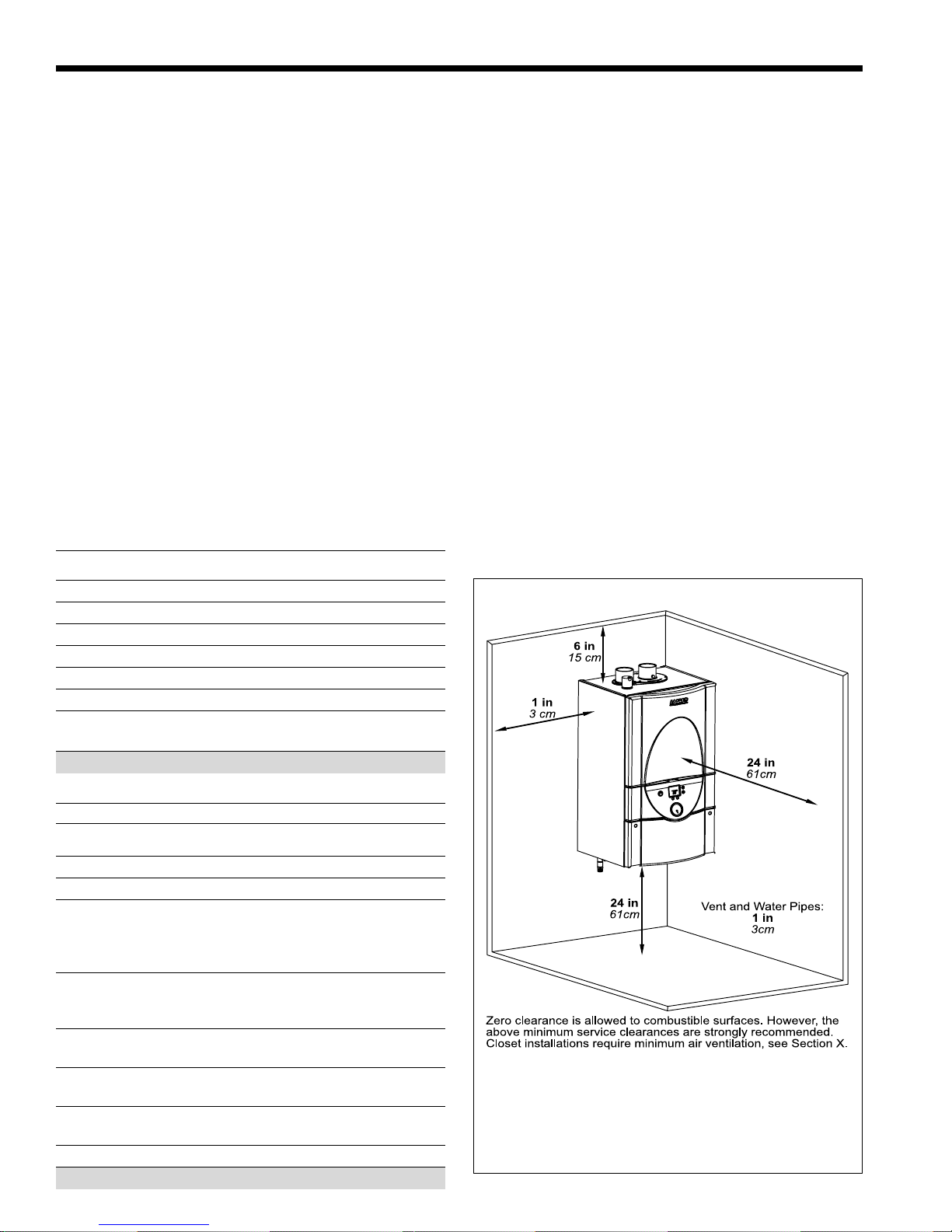
The dimensions and requirements that are shown
in Table 1 should be met when choosing the locations
for the appliance.
2.2 Locating Appliance for Correct Vent
Distance from Outside Wall or
Roof Termination
The forced draft combustion air blower in the
appliance has sufficient power to vent properly when
the guidelines in Table 2 are followed.
NOTE: When located on the same wall, the Mascot II
combustion air intake terminal must be installed a
minimum of 12" below the exhaust terminal.
For concentric vent terminal kit (optional), follow
installation instructions included with the kit.
APPLIANCE
SURFACE INCHES CM
Left Side 6 15
Right Side 6 15
Top 6 15
Closet, Front 6 15
Front 24 61
Vent 1 3
Certified by CSA for zero clearance to
SIZE VENT FT. M VENT FT. M
125 2" 40 6.1 3/5" 40 6.1
125 *3"* 100 30.5 3/5" 40 6.1
Installations in the U.S. require exhaust vent pipe that is a combination
of PVC & CPVC complying with ANSI/ASTM D1785 F441 or stainless
steel complying with UL1738. Installations in Canada require exhaust
vent pipe that is certified to ULC S636.
Intake (air) pipe must be PVC or CPVC that complies with ANSI/ASTM
D1785 F441, ABS that complies with ANSI/ASTM D1527 or
galvanized material.
Installer must comply fully with manufacturer's installation instructions,
to maintain ANSI Z21.13 safety certification.
Closet and alcove installations do not allow the use of PVC under any
circumstances
To calculate max equivalent length, measure the linear feet of the
pipe, and add 5 feet (1.5m) for each elbow used.
* Must use 2x3 adapter within 1 ft. (30cm) of boiler exhaust outlet.
SUGGESTED SERVICE ACCESS CLEARANCE
combustible materials on all sides.
Table 1. Clearances.
INTAKE / EXHAUST
MAX EQUIV. CONCENTRIC MAX EQUIV.
Table 2. Vent / Air Pipe Sizes.
Zero clearance is allowed to combustible surfaces.
However, the above minimum service clearances are
strongly recommended.
Closet installations require minimum air ventilation
(see Section 3).
Figure 4. Locating the Appliance.
Mascot II Boilers and Water Heaters
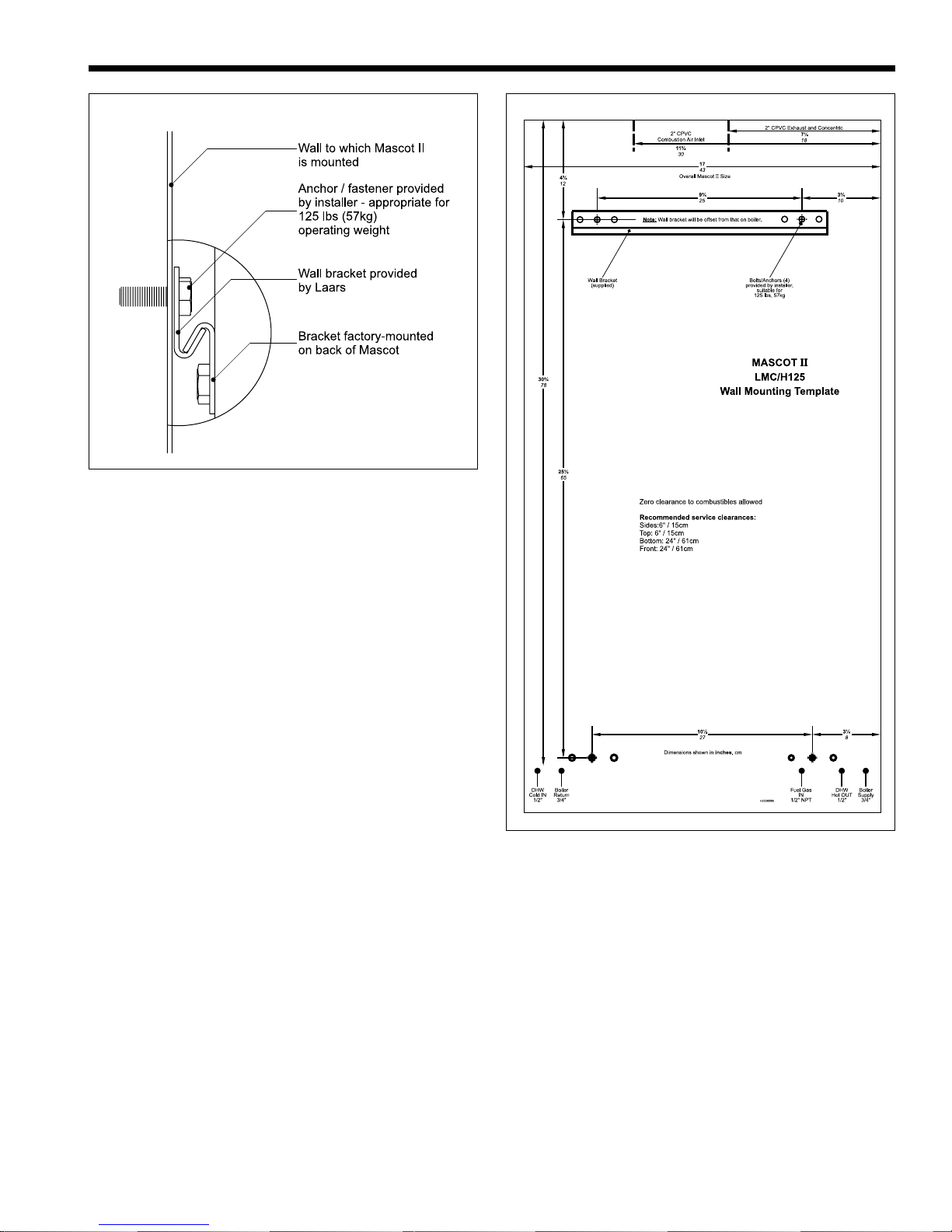
Note: Mascot II
bracket and wall
bracket are
purposely offset.
Figure 5. Mounting Detail.
Page 9
NOTE: Mascot II models include 16" on-center
mounting holes on upper rear of boiler jacket. These
holes are not identified on the mounting template. If
mounting conditions are appropriate, the installer may
opt to use this alternative method in lieu of the standard
wall bracket depicted. Installer must provide
appropriate mounting/anchoring hardware.
Figure 6. Wall Template (not to scale). Full-size template is
included with the unit.
Page 10
LAARS Heating Systems
SECTION 3.
Venting and Combustion Air
Laars Mascot II includes a standard
CPVC vent/combustion air adapter. If
field connections require use of PVC/
CPVC vent materials, the installer must
use proper adhesive to join CPVC and/
or PVC pipe and fittings.
3.1 Combustion Air
Mascot II boilers and water heaters must have
provisions for combustion and ventilation air in
accordance with the applicable requirements for
Combustion Air Supply and Ventilation in the National
Fuel Gas Code, ANSI Z223 1; or in Canada, the Natural
Gas and Propane Installation Code, CSA B149.1. All
applicable provisions of local building codes must also
be adhered to.
A Mascot II unit can take combustion air from
the space in which it is installed, or the combustion
air can be ducted directly to the unit. Ventilation air
must be provided in either case.
3.1.1 Combustion Air from Room
In the United States, the most common
requirements specify that the space shall communicate
with the outdoors in accordance with method 1 or 2,
which follow. Where ducts are used, they shall be of the
same cross-sectional area as the free area of the
openings to which they connect.
Method 1: Two permanent openings, one
commencing within 12" (300mm) of the top and one
commencing within 12" (300mm) of the bottom, of the
HORIZONTAL INTAKE AND EXHAUST PVC VENT TERMINAL KITS
2" PVC 3" PVC
SIZE
125 included optional contact Laars
Concentric vent terminal = 10 ft. pipe length.
SIZE ADAPTER TERMINAL TERMINAL
125 3CGV-VC 3CGV-AD-LAARS 3CVG-HZC
Standard Concentric
CA006000
Table 3a. PVC Vent Terminal Kits.
CONCENTRIC WALL ROOF
Table 3b. Approved Stainless Steel
Terminations and Adapters.
n/a
enclosure shall be provided. The openings shall
communicate directly, or by ducts, with the outdoors or
spaces that freely communicate with the outdoors.
When directly communicating with the outdoors, or
when communicating to the outdoors through vertical
ducts, each opening shall have a minimum free area of 1
square inch per 4000 Btu/hr (550 square mm/kW) of
total input rating of all equipment in the enclosure.
When communicating to the outdoors through
horizontal ducts, each opening shall have a minimum
free area of not less than 1 square inch per 2000 Btu/hr
(1100 square mm/kW) of total input rating of all
equipment in the enclosure.
Method 2: One permanent opening, commencing
within 12" (300mm) of the top of the enclosure, shall be
permitted. The opening shall directly communicate with
the outdoors or shall communicate through a vertical or
horizontal duct to the outdoors or spaces that directly
communicate with the outdoors and shall have a
minimum free area of 1 square inch per 3000 Btu/hr
(734 square mm/kW) of the total input rating of all
equipment located in the enclosure. This opening must
not be less than the sum of the areas of all vent
connectors in the confined space.
Other methods of introducing combustion and
ventilation air are acceptable, providing they conform to
the requirements in the applicable codes listed above.
In Canada, consult local building and safety codes or,
in absence of such requirements, follow CAN/CGA B149.
3.1.2 Ducted Combustion Air
The combustion air can be taken through the wall, or
through the roof. When taken from the wall, it must be
taken from out-of-doors by means of the LAARS
horizontal wall terminal, shown in Table 3. See Table 2 to
select the appropriate diameter air pipe. When taken from
the roof, a field-supplied rain cap or an elbow arrangement
must be used to prevent entry of rain water (see Figure 7).
Use ABS, PVC, CPVC or galvanized pipe for the
combustion air intake (see Table 4), sized per Table 2.
Route the intake to the boiler as directly as possible. Seal
all joints. Provide adequate hangers. The unit must not
support the weight of the combustion air intake pipe.
Maximum linear pipe length allowed is shown in Table 2.
Subtract 5 allowable linear ft. (1.5m) for every elbow used.
The connection for the intake air pipe is at the top of
the unit (see Figure 2).
In addition to air needed for combustion, air shall
also be supplied for ventilation, including air required for
comfort and proper working conditions for personnel.
MATERIAL UNITED STATES CANADA
ABS ANSI/ASTM D1527
PVC, sch 40 ANSI/ASTM D1785 or D2665
CPVC, sch 40 ANSI/ASTM F441
Single wall galv. steel 26 gauge
Table 4. Required Combustion Air Pipe Material.
INSTALLATION STANDARDS
Air pipe material must be chosen
based upon the intended application of the boiler.
Mascot II Boilers and Water Heaters
Page 11
3.2 Venting (Exhaust)
WARNING
Failure to use the appropriate vent material, installation
techniques, glues/sealants could lead to vent failure
causing property damage, personal injury or death.
WARNING
All venting must be installed according to this manual
and any other applicable local codes, including but not
limited to, ANSI Z223.1/NFPA 54, CSA B149.1,
CSAB149.2 and ULC-S636. Failure to follow this
manual and applicable codes may lead to property
damage, severe injury, or death.
The flue temperature of the Mascot II changes
dramatically with changes in operating water
temperature. Therefore, it is necessary to assess the
application of the boiler to determine the required
certified vent class. If the Mascot II is installed in an
application where the ambient temperature is
elevated, and/or installed in a closet/alcove, CPVC or
stainless steel material is required. If the system
temperatures are unknown at the time of
installation, stainless or CPVC material is
recommended.
The Mascot II is a Category IV appliance and may
be installed with PVC and CPVC that complies with
ANSI/ASTM D1785 F441, or a stainless steel venting
system that complies with UL 1738 Standard
(see Table 5).
IN CANADA all venting used must meet the
following requirements:
1. ULC-S636 certified and marked
2. The first 3 feet of venting must be accessible for
visual inspection.
3. All components used in the vent system must be
from a certified manufacturer.
4 . Vent system components must not be mixed
with alternate manufacturers certified
components and/or unlisted components.
5 . The venting must be installed according to the
vent manufacturers installation instructions.
The unit’s vent can terminate through the roof, or
through an outside wall.
See Table 2 to select the appropriate vent pipe
diameter. Vent pipe must pitch upward, toward the vent
terminal, not less than 1/4" per foot, so that condensate
will run back to the Mascot II to drain. Route vent pipe
to the heater as directly as possible. Seal all joints and
provide adequate hangers as required in the venting
system manufacturer’s Installation Instructions.
Horizontal portions of the venting system must be
supported to prevent sagging and may not have any low
sections that could trap condensate. The unit must not
support the weight of the vent pipe. Please see Table 2
for proper diameter vs. length allowed.
INSTALLATIONS IN CANADA require the use
of venting material certified to ULCS636. All Gas
vents connected to the Mascot II, plastic, stainless
steel or otherwise must be certified to this ULC
standard. Appropriate selection of vent material is
very important for proper performance and safe
operation of the Mascot II.
The flue temperature of the Mascot II changes
dramatically with changes in operating water
temperature. Therefore, it is necessary to assess the
application of the boiler to determine the required
certified vent class. If the Mascot II is installed in an
application where the outlet water temperature
exceeds 145°F, and/or installed in a closet, class IIB
or higher vent material is required. If the system
temperatures are unknown at the time of
installation, class IIB or higher venting material is
recommended.
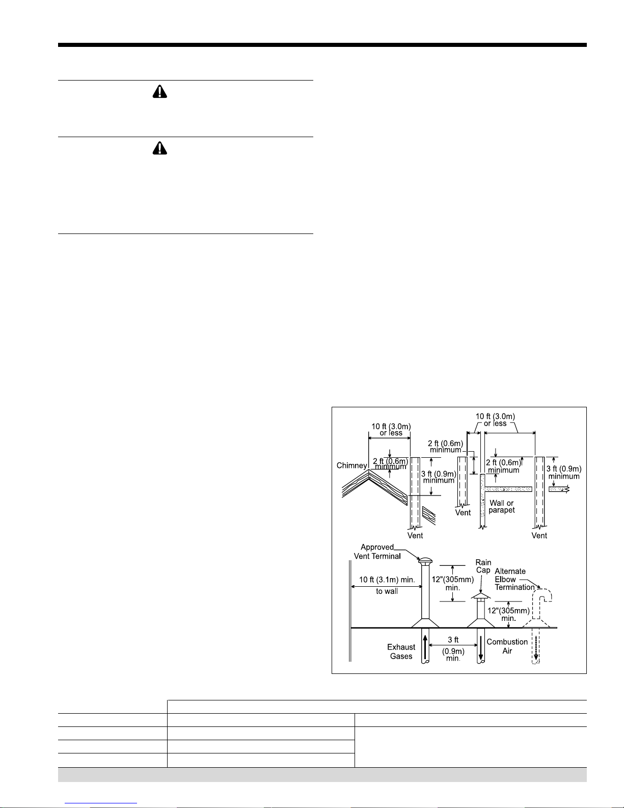
Figure 7. Combustion Air and Vent Through Roof.
INSTALLATION STANDARDS
MATERIAL UNITED STATES CANADA
Stainless Steel UL 1738
PVC, sch 40 ANSI/ASTM D178 venting material. The venting material must be chosen
CPVC, sch 40 ANSI/ASTM F441
Table 5. Required Exhaust Vent Material.
Venting must be ULC-S636 certified for use as
based upon the intended application of the boiler.
Page 12
LAARS Heating Systems
IMPORTANT NOTE ABOUT COMMON VENTING: A
single vent that is shared by multiple Mascot II units
MUST be engineered by a competent venting
specialist, and involves the selection of draft inducing
equipment, hardware and controls to properly balance
flue gas pressures. Do not common vent Mascot II
units unless the vent system meets this
requirement. Mascot II units are never permitted to
share a vent with Category I appliances.
A condensate drain trap is built into Mascot II.
Connect a 3/4" PVC pipe between the drain
connection and a floor drain (or condensate pump if a
floor drain is not accessible).
The condensate drain must be installed so as to
prevent accumulation of condensate. When a
condensate pump is not used, the tubing must
continuously slope downward toward the drain with no
spiraling.
Consult local codes for disposal method.
Caution
Condensate is mildly acidic (pH
some floor drains and/or pipes, particularly those that
are metal. Ensure that the drain, drainpipe, and
anything that will come in contact with the
condensate can withstand the acidity, or neutralize
the condensate before disposal. Damage caused by
failure to install a neutralizer kit or to adequately
treat condensate will not be the manufacturer’s
responsibility.
..
.5), and may harm
..
3.3 Locating Vent & Combustion Air
Terminals
3.3.1 Side Wall Vent Terminal
The appropriate Laars side wall vent terminal must
be used. The terminal must be located in accordance
with ANSI Z223.1/NFPA 54 and applicable local codes.
In Canada, the installation must be in accordance with
CSA B149.1 or .2 and local applicable codes. Consider
the following when installing the terminal:
1. Figure 9 shows the requirements for mechanical
vent terminal clearances for the U.S. and Canada.
2. Vent terminals for condensing appliances or
appliances with condensing vents are not
permitted to terminate above a public walkway, or
over an area where condensate or vapor could
create a nuisance or hazard.
3. Locate the vent terminal so that vent gases cannot
be drawn into air conditioning system inlets.
4. Locate the vent terminal so that vent gases cannot
enter the building through doors, windows, gravity
inlets or other openings. Whenever possible, avoid
locations under windows or near doors.
5. Locate the vent terminal so that it cannot be
blocked by snow. The installer may determine
that a vent terminal must be higher than the
minimum shown in codes, depending upon local
conditions.
6. Locate the terminal so the vent exhaust does not
settle on building surfaces or other nearby objects.
Vent products may damage surfaces or objects.
7. If the boiler or water heater uses ducted
combustion air from an intake terminal located on
the same wall, see Figure 9 for proper spacing and
orientation.
If the vent termination is located in an area
exposed to high winds, an optional PVC tee (the same
diameter as the vent pipe) may be used. The tee'd vent
termination offers greater protection from wind related
operating issues.
3.3.2 Side Wall Combustion Air Terminal
The LAARS side wall combustion air terminal, or
concentric terminal (see Table 3), must be used when
the heater takes air from a side wall. Consider the
following when installing the terminal (see Figure 9):
1. Do not locate the air inlet terminal near a source of
corrosive chemical fumes (e.g., cleaning fluid,
chlorine compounds, etc.)
2. Locate the terminal so that it will not be subject to
damage by accident or vandalism. It must be at
least 7 feet (2.1m) above a public walkway.
3. Locate the combustion air terminal so that it
cannot be blocked by snow. The National Fuel Gas
Code requires that it be at least 12 inches (30cm)
above grade, but the installer may determine it
should be higher, depending upon local conditions.
4. For concentric vent, follow instructions
included with vent kit.
5. Multiple vent kits should be installed such that the
horizontal distance between outlet group and inlet
group is 36" (90cm) minimum.
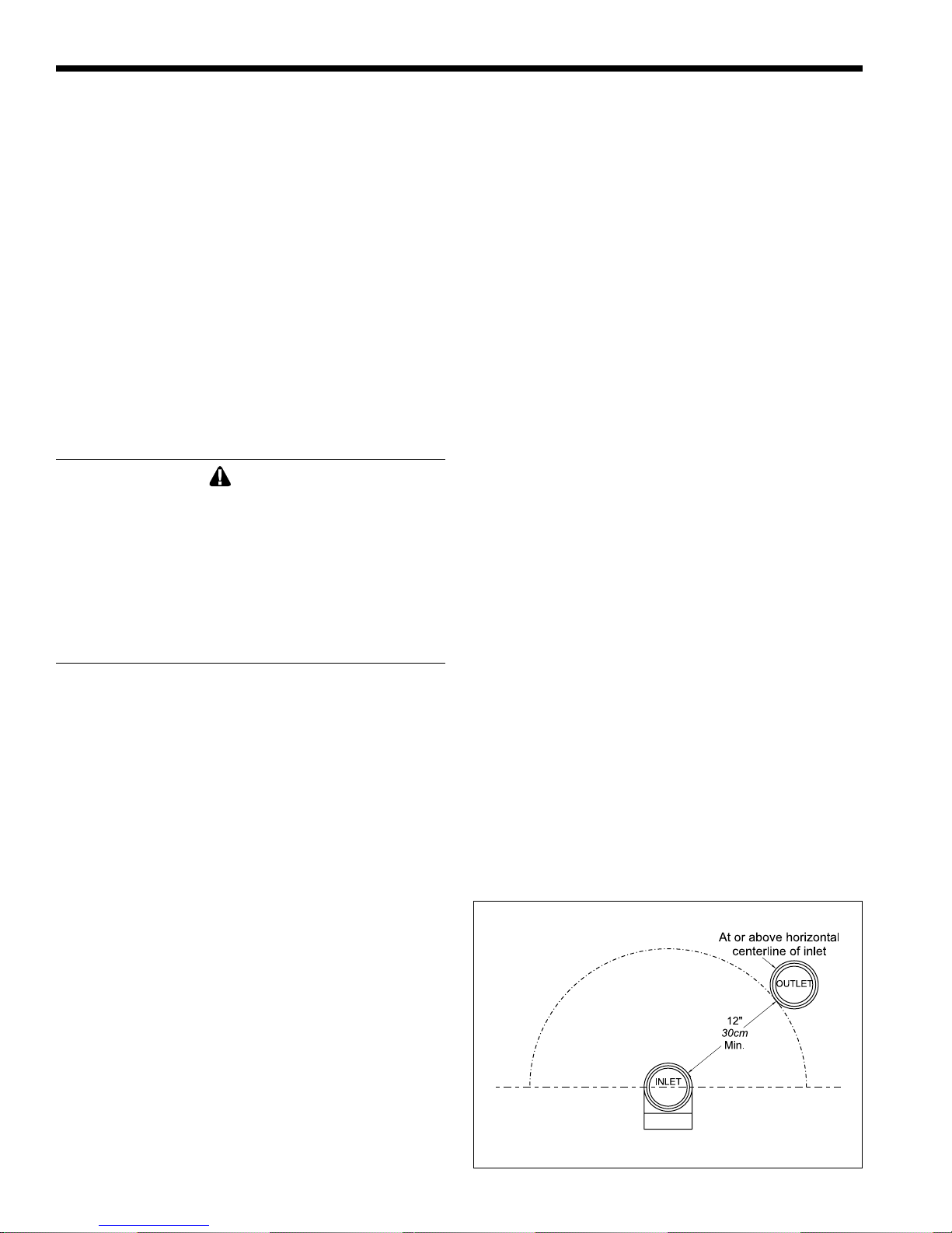
6. Vent outlet must be no lower than the center of the
air inlet, and must be at least 12" (30cm) away
from the air inlet (see Figure 8).
Figure 8. Minimum Venting Distance.
Mascot II Boilers and Water Heaters
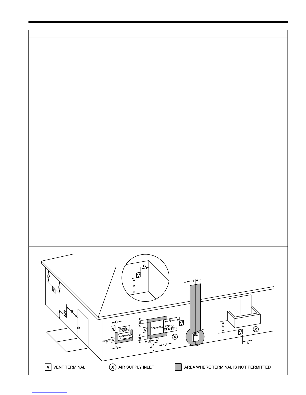
U.S. Installations (see note 1) Canadian Installations (see note 2)
A= Clearance above grade, veranda, porch, 12 inches (30 cm) 12 inches (30 cm)
deck, or balcony See note 6 See note 6
B= Clearance to window or door that may be Direct vent only: 12 inches (30cm); 36 inches (91 cm)
opened Other than Direct vent: 4 ft (1.2m) below or to
side of opening; 1 ft (30cm) above opening
C= Clearance to permanently closed window See note 4 See note 5
D= Vertical clearance to ventilated soffit located
above the terminal within a horizontal See note 4 See note 5
distance of 2 feet (61cm) from the center
line of the terminal
E= Clearance to unventilated soffit See note 4 See note 5
F= Clearance to outside corner See note 4 See note 5
G= Clearance to inside corner 3 feet (91 cm) minimum See note 5
H= Clearance to each side of center line 3 feet (91 cm) within a height 15 feet
extended above meter/regulator assembly See note 4 above the meter/regulator assembly
I= Clearance to service regulator vent outlet See note 4 3 feet (91 cm)
J= Clearance to nonmechanical air supply Direct vent only: 12" (30cm) 80-285; 36" (91cm)
inlet to building or the combustion air inlet 399-850. Other than Direct vent: 4 ft (1.2m) below 36 inches (91 cm)
to any other appliance or to side of opening; 1 ft (30cm) above opening
K= Clearance to a mechanical air supply inlet 3 feet (91 cm) above if within 10 feet (3 m) 6 feet (1.83 m)
horizontally
L= Clearance above paved sidewalk or paved Vent termination not allowed in this location Vent termination not allowed in this
driveway located on public property for category IV appliances. location for category IV appliances.
M= Clearance under veranda, porch, deck, See note 4 12 inches (30 cm) (see note 3)
or balcony
Notes:
1. In accordance with the current ANSI Z223.1 / NFPA 54 National Fuel Gas Code.
2. In accordance with the current CAN/CGA-B149 Installation Codes.
3. Permitted only if veranda, porch, deck, or balcony is fully open on a minimum of two sides beneath the floor.
4. For clearances not specified in ANSI Z223.1 / NFPA 54, clearance is in accordance with local installation codes and the requirements of the
gas supplier.
5. For clearances not specified in CAN/CGA-B149, clearance is in accordance with local installation codes and the requirements of the gas
supplier.
6. IMPORTANT: terminal must be placed such that it remains a minimum 12" above expected snow line. Local codes may have more
specific requirements, and must be consulted.
Page 13
Figure 9. Combustion Air and Vent Through Side Wall.
*When vent terminal is less than 10 feet (3m) horizontally
from a forced air inlet, the terminal must be at least 3 feet
(0.9m) above the air inlet.
Page 14
LAARS Heating Systems
3.3.3 Vertical Vent Terminal
When the unit is vented through the roof, the vent
must extend at least 3 feet (0.9m) above the point at
which it penetrates the roof. It must extend at least 2
feet (0.6m) higher than any portion of a building within
a horizontal distance of 10 feet (3.0m), and high enough
above the roof line to prevent blockage from snow.
When the combustion air is taken from the roof, the
combustion air must terminate at least 12" (30cm)
below the vent terminal (see Figure 7).
3.3.4 Vertical Combustion Air Terminal
When combustion air is taken from the roof, a
field-supplied rain cap or an elbow arrangement must be
used to prevent entry of rain water (see Figure 7). The
opening on the end of the terminal must be at least 12"
(30cm) above the point at which it penetrates the roof,
and high enough above the roof line to prevent blockage
from snow. When the vent terminates on the roof, the
combustion air must terminate at least 12" (30cm)
below the vent terminal.
3.3.5 Installations in the Commonwealth of
Massachusetts
In Massachusetts the following items are required
if the side-wall exhaust vent termination is less than
seven (7) feet above finished grade in the area of the
venting, including but not limited to decks and porches.
From Massachusetts Rules and regulations 248 CMR
5.08
1. Installation of Carbon Monoxide Detectors
At the time of installation of the side wall vented
gas fueled appliance, the installing plumber or
gasfitter shall observe that a hard-wired carbon
monoxide detector with an alarm battery back-up is
installed on the floor level where the gas appliance
is to be installed. In addition, the installing plumber
or gasfitter shall observe that a battery operated or
hard-wired carbon monoxide detector with an alarm
is installed on each additional level of the dwelling,
building or structure served by the side-wall horizontally vented gas fueled equipment. It shall be the
responsibility of the property owner to secure the
services of qualified licensed professionals for
installation of hard-wired carbon monoxide detectors.
a. In the event that the side-wall horizontally vented
gas fueled equipment is installed in a crawl space or
an attic, the hard-wired carbon monoxide with alarm
and battery back-up may be installed on the next
adjacent floor level.
b. In the event that the requirements of the subdivision cannot be met at the time of completion of
installation, the owner shall have a period of thirty
(30) days to comply with the above requirements,
provided, however, that during said thirty (30) day
period, a battery operated carbon monoxide detector
with an alarm be installed.
2. Approved Carbon Monoxide Detectors
Each carbon monoxide detector shall comply with
NFPA 720 and be ANSI/UL 2034 listed and IAS
certified.
3. Signage
A metal or plastic identification plate shall be
permanently mounted to the exterior of the building
at a minimum height of eight (8) feet above grade
directly in line with the exhaust vent terminal for
horizontally vented gas fueled heating appliance or
equipment. The sign shall read, in print no less than
one-half (1/2) inch in size: "GAS VENT DIRECTLY BELOW, KEEP CLEAR OF ALL
OBSTRUCTIONS".
4. Inspection
The state or local gas inspector of the side-wall
horizontally vented gas fueled appliance shall not
approve the installation unless, upon inspection, the
inspector observes carbon monoxide detectors and
signage installed in accordance with the provisions
of 248 CMR 5.08(2)(a) 1-4.
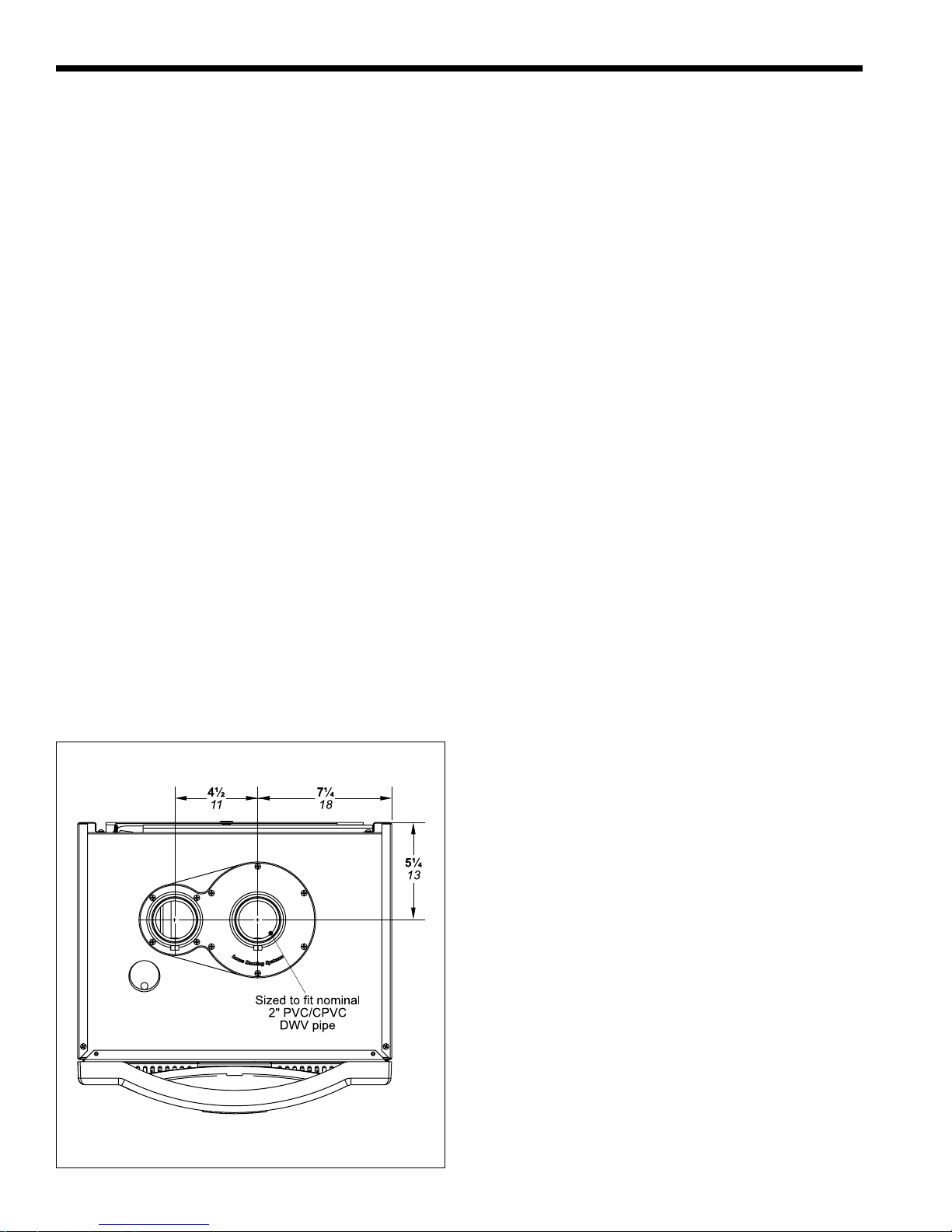
Optional concentric vent kit sold separately.
Figure 10. Vent Dimensions, 2-Pipe System.
3.4 Common Vent Test
NOTE: This section does not describe a method for
common venting Mascot II units. It describes what must
be done when a unit is removed from a common vent
system. Mascot II units require special vent systems
and fans for common vent. Contact the factory if you
have questions about common venting Mascot II units.
When an existing boiler is removed from a
common venting system, the common venting system is
likely to be too large for proper venting of the
appliances remaining connected to it.
At the time of removal of an existing boiler, the

Mascot II Boilers and Water Heaters
following steps shall be followed with each appliance
remaining connected to the common venting system
placed in operation, while the other appliances
remaining connected to the common venting system are
not in operation.
1. Seal any unused openings in the common venting
system.
2. Visually inspect the venting system for proper size
and horizontal pitch and determine there is no
blockage or restriction, leakage, corrosion and other
deficiencies which could cause an unsafe condition.
3. Insofar as it is practical, close all building doors and
windows and all doors between the space in which
the appliances remaining connected to the common
venting system are located and other spaces of the
building. Turn on clothes dryers and any appliance
not connected to the common venting system. Turn
on any exhaust fans, such as range hoods and
bathroom exhausts, so they will operate at
maximum speed. Do not operate a summer exhaust
fan. Close fireplace dampers.
4. Place in operation the appliance being inspected.
Follow the lighting instructions. Adjust thermostat
so the appliance will operate continuously.
5. Test for spillage at the draft hood relief opening
after 5 minutes of main burner operation. Use the
flame of a match or candle, or smoke from a
cigarette, cigar or pipe.
6. After it has been determined that each appliance
remaining connected to the common venting system
properly vents when tested as outlined above, return
doors, windows, exhaust fans, fireplace dampers
and any other gas burning appliance to their
previous conditions of use.
7. Any improper operation of the common venting
system should be corrected so that the installation
conforms to the National Fuel Gas Code, ANSI
Z223.1/NFPA 54 and/or CSA B149.1, Installation
Codes. When resizing any portion of the common
venting system, the common venting system should
be resized to approach the minimum size as determined using the appropriate tables and guidelines in
the National Fuel Gas Code, ANSI Z223.1 NFPA
54 and/or CSA B149.1, Installation Codes.
Page 15
Page 16
LAARS Heating Systems
SECTION 4.
Gas Supply and Piping
4.1 Gas Supply and Piping
Gas piping should be supported by suitable
hangers or floor stands, not the appliance.
Review the following instructions before
proceeding with the installation.
1. Verify that the appliance is fitted for the proper type of
gas by checking the rating plate. Mascot II will
function properly without the use of high altitude
modification at elevations up to 10,000 feet (3050 m).
2. The maximum inlet gas pressure must not exceed
13" W.C. (3.2kPa). The minimum inlet gas
pressure is 4" W.C. (1.0kPa).
3. Refer to Tables 6A, 6B, 6C and 6D to size piping.
4. Run gas supply line in accordance with all
applicable codes.
5. Locate and install manual shutoff valves in
accordance with state and local requirements.
6. A sediment trap must be provided upstream of the
gas controls.
7. All threaded joints should be coated with piping
compound resistant to action of liquefied
petroleum gas.
8. The appliance and its individual shutoff valve
must be disconnected from the gas supply piping
during any pressure testing of that system at test
pressures in excess of 1/2 PSIG (3.45kPa).
9. The unit must be isolated from the gas supply
system by closing its individual manual shutoff
valve during any pressure testing of the gas supply
piping system at test pressures equal to or less than
1/2 PSIG (3.45kPa).
10. The appliance and its gas connection must be leak
tested before placing it in operation.
11. Purge all air from gas lines.
WARNING:
Open flame can cause gas to ignite and result in
property damage, severe injury, or loss of life.
NOTE: The Mascot II appliance and all other gas
appliances sharing the gas supply line must be firing at
maximum capacity to properly measure the inlet supply
pressure. The pressure can be measured at the supply
pressure port on the gas valve. Low gas pressure could
be an indication of an undersized gas meter, undersized
gas supply lines and/or an obstructed gas supply line.
MASCOT II NATURAL GAS REQUIRED
SIZE CU FT / HR.
125 125
TO SIZE PIPING:
Measure linear distance from meter outlet to last boiler. Add total
input of all boilers and divide by 1000 to obtain cu ft / hr required.
Add total equivalent length of fittings used according to Table 6B.
Align total length (pipe and fittings) on left side column of Table 6C
with highest cubic feet of gas required.
Notes:
Consult and confirm with Applicable Fuel Gas Code before beginning
work. Verify gas inlet pressure is between 4 and 13 in W.C. before
starting boiler.
Table 6A.
EQUIVALENT LENGTHS OF STRAIGHT PIPE FOR TYPICAL SCH 40 FITTINGS
FITTING 1/2" 3/4" 1"
90° ELBOW 3.6 4.4 5.2
TEE 4.2 5.3 6.6
SCH 40 METAL PIPE CAPACITY FOR 0.60 SPECIFIC GRAVITY NATURAL GAS
NOMINAL PIPE SIZE @ 0.30" W.C. PRESSURE DROP
LENGTH 1/2" 3/4"
FT CUBIC FEET OF GAS PER HOUR
20 92 190
40 130
60 105
80 90
100
SCHED 40 METAL PIPE CAPACITY FOR 1.50 SPECIFIC GRAVITY
NOMINAL PIPE SIZE @ 11" W.C. INLET AND 0.5" W.C. PRESSURE DROP
SIZE 1/2" 3/4"
LENGTH MAXIMUM CAPACITY IN THOUSANDS OF BTU PER HOUR
20 200 418
40 137 287
60 110 231
80 94 197
100 84 175
NOTES: 1. Follow all local and national LP gas codes for line sizing and
equipment requirements. 2. Verify that inlet gas pressure remains between
4 and 13 inches of water column before and during operation.
Source: ANSI Z223.1-80 National Fuel Gas Code.
NOMINAL PIPE SIZE
LINEAR FEET
Table 6B.
Table 6C.
UNDILUTED PROPANE
Table 6D.
 Loading...