

Page 1

/Jandy Products
1999 Products and Parts Catalog
Page 3
Heaters
H
E
A
T
E
R
S
Page 2
Page 4
/Jandy Products
1999 Products and Parts Catalog
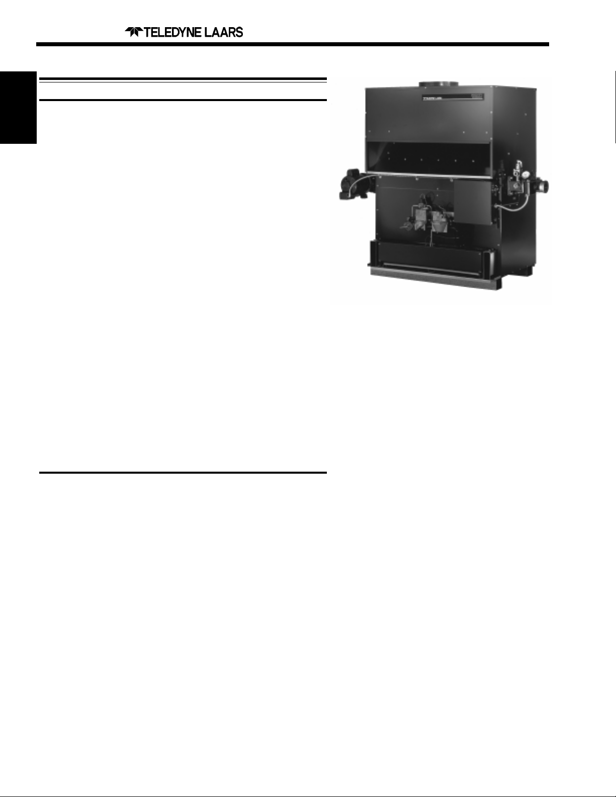
Laars Residential and Commercial Pool Heaters
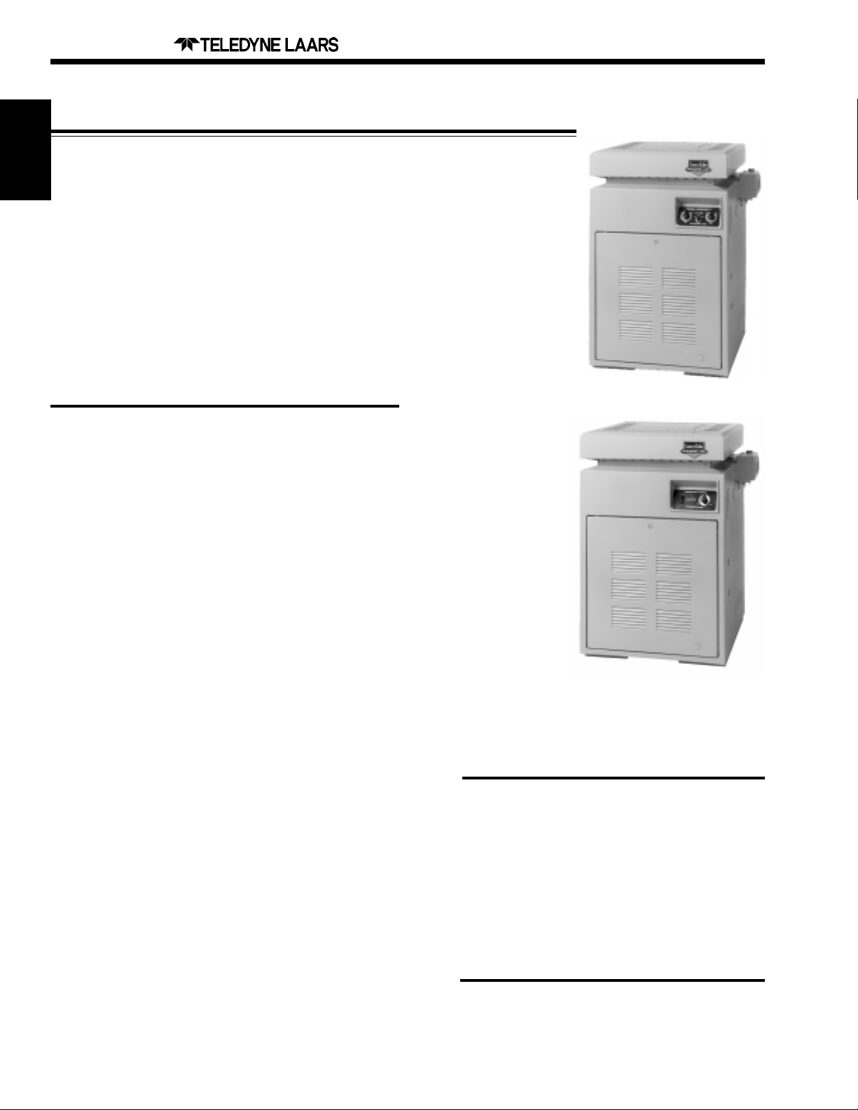
Laars Lite™
The Laars Lite™ is built for dependability and efficiency . At the heart of
its efficiency is an ingenious combustion chamber , surrounded by a
Heaters
ceramic fiber that works better than any other insulation material. The
Laars Lite™ also offers easy installation, convenient control and a variety
of features, including an electronic thermostat, pilot light ignition system,
and extended life of the main burners and jacket. The LLD model has a
self-cleaning, hot surface ignition which provides quick start-up every
time and prevents sooting. No burner tray removal is required (LLD) and
the igniter can be easily replaced with one screw . The Laars Lite™ is
weather resistant and designed for harsh wind and rain conditions. A
vent cap further enhances performance in severe weather conditions.
The Laars Lite™ carries an exceptional 5 year limited warranty .
Model # Ignition Thermostat Ctn. Weight
125,000 BTU, Natural Gas, Cast Iron Headers, Heater Only
LLG125N Millivolt Single 148
LLD125N Electronic Dual 148
Laars LLD
125,000 BTU, Propane Gas, Cast Iron Headers, Heater Only
LLG125P Millivolt Single 148
LLD125P Electronic Dual 148
175,000 BTU, Natural Gas, Cast Iron Headers, Heater Only
LLG175N Millivolt Single 175
LLD175N Electronic Dual 175
175,000 BTU, Propane Gas, Cast Iron Headers, Heater Only
LLG175P Millivolt Single 175
LLD175P Electronic Dual 175
250,000 BTU, Natural Gas, Cast Iron Headers, Heater Only
LLG250N Millivolt Single 182
LLD250N Electronic Dual 182
250,000 BTU, Propane Gas, Cast Iron Headers, Heater Only
LLG250P Millivolt Single 182
LLD250P Electronic Dual 182
325,000 BTU, Natural Gas, Cast Iron Headers, Heater Only
LLG325N Millivolt Single 214
LLD325N Electronic Dual 214
325,000 BTU, Propane Gas, Cast Iron Headers, Heater Only
LLG325P Millivolt Single 214
LLD325P Electronic Dual 214
Laars LLG
Laars Lite™ Pool & Spa Heater
Options
Bronze Headers
A.S.M.E. Certification
Salt Water Construction (includes Cupro Nickel
Tubes, Monel Sensor , Bronze Headers and
Stainless Steel Fittings)
400,000 BTU, Natural Gas, Cast Iron Headers, Heater Only
LLG400N Millivolt Single 228
LLD400N Electronic Dual 228
400,000 BTU, Propane Gas, Cast Iron Headers, Heater Only
LLG400P Millivolt Single 228
LLD400P Electronic Dual 228
INSTALLATION KITS
10561401-05 INDOOR - DRAFTHOOD KIT
10561501-05 HIGH WIND - VENT CAP KIT
Page 3
/Jandy Products
1999 Products and Parts Catalog
HEATER SELECTION GUIDE
Page 5
Heaters
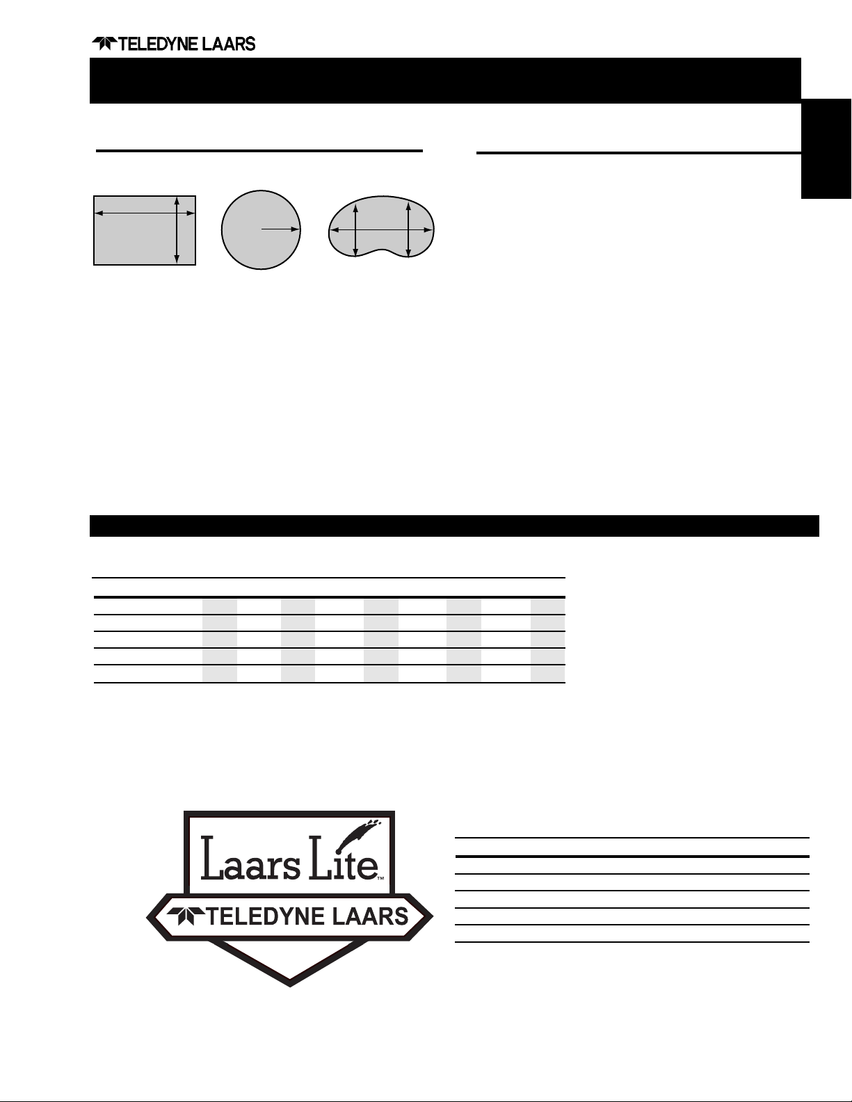
Pool Sizing
Determine your pool’s surface area in square feet.
L
R
W
Area = L x W Area = R x R x 3.14 Area = (A + B) x L x .45
Locate in the table below, the surface are equal to or
slightly greater than the pool’s surface area, read to the
left and select the appropriate heater.
For indoor pool installations, divide the pool’s surface
area by three.
T ables are based on a 30°F temperature rise, 3 1/2
MPH wind velocity and elevation of up to 2,000 feet
above sea level.
AB
L
LAARS LITE™ SIZING CHART
Spa Sizing
Determine your spa capacity in gallons (surface area x
average depth x 7 1/2).
The reference tables list the time required in minutes
to raise the temperature of the spa/hot tub by 30°F.
Locate in the table below, the spa/hot tub size in
gallons. Select the desired time to raise the spa/hot
tub temperature 30°F , read to the left and select the
appropriate heater.
This guide can be adjusted for other temperature rises.
For example, if you desire a 15°F increase in temperature, simply divide the time for 30°F rise by the 15°F
increase (30/15=2).
Note: Heat losses and/or heat absorbed by spa walls or
other objects will add to heat-up time.
Spa sizing is based on an insulated and covered spa.
Always cover your spa or hot tub when not in use to
minimize heat loss and evaporation.
POOL HEATER
Model No. 12 5 17 5 25 0 32 5 40 0
T emp. Diff. Maximum Pool Surface Area (Sq. Ft.)
15°F
20°F
25°F
30°F
35°F
Shaded columns indicate sizing with a 0 MPH wind. Example: Rectangular
pool, 20 feet x 40 feet, with desired temperature rise of 25°F: 20 x 40 = 800
square foot surface area, the recommended heater is the Laars Lite™ LLG or
LLD 250.
667 889
500 667
400 533
333 444
286 381
933 1244
700 933
560 747
467 622
400 533
1333 1778
1000 1333
800 1067
687 889
571 762
1733 231 1
1300 1733
1040 1387
867 1556
743 990
2133 2844
1600 2133
1280 1707
1067 1422
914 1219
Model No. 12 5 17 5 25 0 32 5 40 0
Spa Size (Gal.) Time to Heat Spa 30°F (Minutes)
200
400
600
800
1000
SPA HEATER
30
60
90
120
150
21
43
64
86
107
15
30
45
60
75
12
23
35
46
58
9
19
28
37
47
Example: To heat a 400 gallon spa 30°F in 30 minutes,
the recommended heater is the Laars Lite™ LLG or LLD
250.
Page 4
Page 6
/Jandy Products
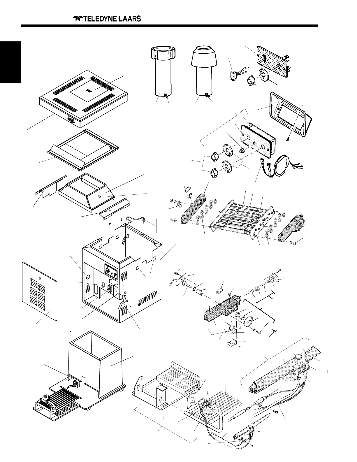
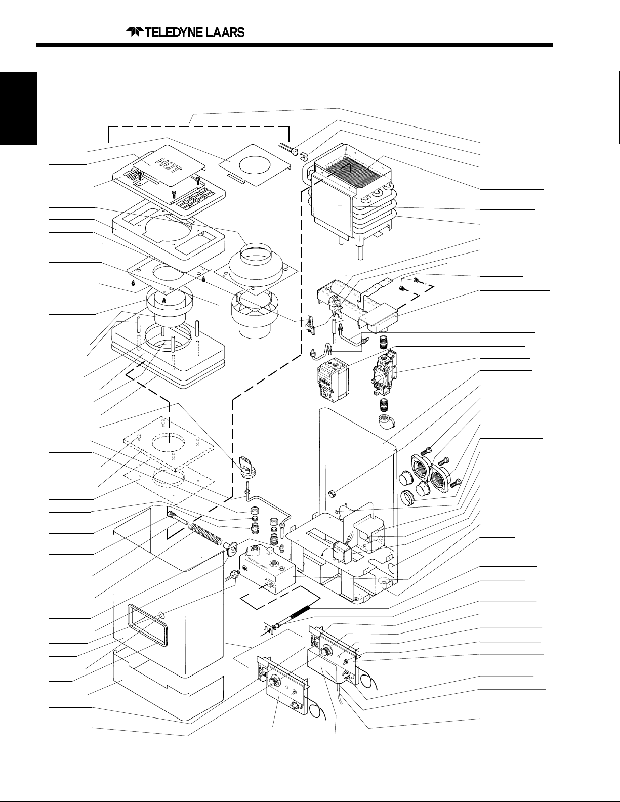
LAARS LITE™, Manufactured From 1997
1999 Products and Parts Catalog
20
21
Heaters
57
59
101
82
100
58
62
40
63
37,
38,
39
96
67
99
30
64
74
69
67
26
23
22
20
93
31
19
33,
32
94
70,71
95
72,
73
74
98
10
49
8,9
51-56
97
50
81
11
12
13A
36
27
17
35
15
29
14
28
13
68
41
102
42
47
16
90
86
77,80
78
43
44
46
6
89
76
91
88
75
79
84,85
1
92
87
2
5
3
4
7
12
Page 5

/Jandy Products
1999 Products and Parts Catalog
Page 7
LAARS LITE™ Pool and Spa Heaters
Key Model ORDER
No Description No P ART NO
1 Pilot, Main Burner Assemby, LPG All R0099200
1 Pilot, Main Burner Assembly, NAT All R0099100
2 Pilot Burner, NAT All R0096700
2 Pilot Burner, LPG All R0096800
2A Pilot Shield All R0323300
3 Pilot Generator All W0036901
4 Ceramic Insulator Assembly All R0011600
5 Burner, Main w/Pilot Bracket All 10457500
6 High Voltage Lead Assembly All R0099000
7 Pilot Tubing All R0037000
8 Piezo Lighter Assembly All R0096800
9 Piezo Lighter Knob All R0097000
10 Ignitor - LLD All R0317200
MAIN GAS ASSEMBLY
11 Burner Tray Assy, NAT (Note 1) - LLG 125-400 R0098601-05
11 Burner Tray Assy, LPG (Note 1) - LLG 125-400 R0098701-05
11 Burner Tray Assy, NAT (Note 1) - LLD 125-400 R0316901-05
11 Burner Tray Assy, LPG (Note 1) - LLD 125-400 R0319501-05
12 Burner Tray, Shelf Only 125-400 R0317001-05
13 Gas Valve, NAT - LLG All R0096400
13 Gas Valve, LPG - LLG All R0096900
13 Gas Valve, NAT - LLD All R0317100
13 Gas Valve, LPG - LLD All R0319600
13A Gas Orifice, NAT
13A Gas Orifice, LPG
14 Anti-Rotation Bracket All 10577200
15 Mounting Bracket Assembly All 10419200
16 Burner, Main All L0052300
17 Burner Manifold (Note 2)
ELECTRICAL SYSTEM
18 Temperature Control Assembly - LLG All R0058200
19 Wire Harness All R0058000
20 Plate Assembly All 10456300
21 On-Off Switch All R0099800
22 Temperature Control Label All H0105300
23 Temperature Control Assembly - LLD All R0011700
24 Wire Harness Assembly All 10457800
25 Plate Assembly All 10594600
26 Knob, Single Bar All R0099900
Key Nos. 27- 36 are for both R582 & R117
27 T emperature Sensor All R0011800
28 Protector Sleeve, Bulb All 10444900
29 "O" Ring, Temperature Control Bulb All E0116400
30 Thermostat Knob, Black All R0010700
31 "T emp-Lok" Stop Plate (Not Shown) Al l 10583100
32 Temperature Control Gasket All S0070000
33 Bezel All S0069800
34 Stop Plate Screw All F0033300
35 Retainer Bracket All 10447300
36 Retainer Bracket Screw All F0009100
37 Pressure Switch & Siphon Loop Assembly All R0097600
38 Pressure Switch, 2 PSI All R0013200
38 Pressure Switch, 1 PSI All R0011300
38 Pressure Switch, 1-10 PSI All R0015500
39 Siphon Loop Assembly All R0057800
40 Redundant High-Limit - LLG All R0313900
41 High-Limit Switch Assembly All R0023200
42 High-Limit Switch, 135°F All R0022700
43 High-Limit Switch, 150°F All R0023000
44 High-Limit Switch Retainer Clip All 10418400
45 High-Limit Switch Retainer Boot All S0098900
46 High-Limit Switch Cover All 10418300
47 High-Limit Switch Wire Harness All 10419300
48 Fusible Link Assembly All R0012200
49 Fusible Link Bracket All 10479900
50 Terminal Block All R0097800
51 Ignition Control Assembly - LLD All R0317500
52 Ignition Control - LLD All R0325200
53 Harness Assembly All R0059800
54 Transformer (1 15V-220V/24V) All R0061100
55 Ignition Control Panel All 10451200
56 In-Line Fuse Assembly All 10480000
PILOT GAS SYSTEM - LLG
(Note 1)
(Note 1)
All L0032200
All L0032900
Key Model ORDER
No Description No PART NO
VENT SYSTEM
57 T op Enclosure 125-400 R0313201-05
58 T op Filler 125-400 10535201-05
59 Rainshield Kit 125-400 R0318301-05
62 Flue Collector Assembly 125-400 R0316401-05
63 Outdoor Vent Cap 125-400 10561501-05
64 Indoor Drafthood 125-400 10561401-05
65 Flue Transition Plate 125-400 10861901-05
66 Adapter Plate 125-400 10535301-05
67 Clip All 10211000
WATER SYSTEM
68 Inlet/Outlet Header, 2" All R0056400
68 Inlet/Outlet Header, Bronze, 2" All R0016800
69 Return Header All R0058300
69 ReturnHeader, Bronze All R0054600
70 Header Bolt Assembly All R0057000
71 Bolt for Headers, 2 1/2" All F0046100
72 Washer for Headers All F0011100
73 Nut for Headers All F0003100
74 Header Gasket Assembly (Set of 18) All R0050800
75 Flange & Gasket Assembly
76 Flange, 2" All 10573500
77 Flange Gasket, 2" All S0078000
78 Flange Sleeve, 2" All S0078200
79 Flange Bolt All F0031700
80 Flange Gasket, 1 1/2 - 2" All S0078100
81 Grommet for Drain Plug All R0316300
82 Grommet, Slitted All S0071100
83 Hole Plug All S0098700
84 Drain Plug All P0026800
85 Drain Plug Bushing All P0018500
86 Brass Plug, 3/4" All P0027000
87 By-Pass Assembly All R0054900
88 By-Pass Valve Rod All S0074300
89 By-Pass Valve Disc All R0011500
90 By-Pass Valve Control Cap All 10452200
91 By-Pass Valve Spring, Purple 125 S0079900
91 By-Pass Valve Spring, White 175 S0061400
91 By-Pass Valve Spring, Red 250 S0061300
91 By-Pass Valve Spring, Blue 325 S0061200
91 By-Pass Valve Spring, Black 400 S0070100
92 By-Pass Valve Gasket All R0011400
93 Heat Exchanger Tube Assembly 125-400 R0018101-05
94 Heat Exchanger Baffle (8 Required) 125-400 10697401-05
95 Baffle Retainer All S0083900
96 Heat Exchanger Support Clip All 10457000
FIREBOX COMPONENTS
97 Complete Chamber Assembly 125-400 R0316701-05
JACKET COMPONENTS
98 Door with Latch 125-400 R0313401-05
99 Jacket Assembly, Less Top Assembly 125-400 R0316501-05
100 Gap Closure, Inlet/Outlet All 10448200
101 Gap Closure, Return All 10448300
102 Insulation and Retainer All 10462200
OPTIONAL COMPONENTS
Non Combustible Base 125-400 10521701-05
Pressure Relief Valve 3/4" NPT, 75 PSI All R0040400
Touch Up Spray Paint, Light Beige All X0021100
Notes:
1. For altitudes 2,000 Ft above sea level, call factory for orifice size.
2. See Appendix.
3. Two included in assembly.
(Note 3 )
All R0055000
Heaters
Page 6

Page 8
/Jandy Products
Hi-E2™ Commercial Pool and Spa Heater
Engineered to warm your bottom line, the Hi-E2™ from T eledyne
Laars/Jandy Products is the #1 commercial pool and spa heater
with a 95% efficiency rating. With unmatched energy efficiency ,
innovative, trouble-free features and installation flexibility , the Hi-
Heaters
E2™ is the best heater available for indoor , outdoor, new construction or retrofit. The Hi-E2™ also features direct connection to PVC
pipe, easy multiple unit stacking for larger facilities, a unique forceair system for reliable performance in extreme weather conditions,
dual thermostats for different temperature settings for the pool and
spa, and a patented hot surface ignition system. Plus, the Hi-E2™
can reduce your operating costs by 30% or more and is backed by
a comprehensive 5-year limited warranty . A leasing plan is available for commercial properties.
Model # Ignition Thermostat Ctn. Weight
220,000 BTU Input, Natural Gas, Bronze Headers
EHE220NC Electronic Dual 2 06
1999 Products and Parts Catalog
220,000 BTU Input, Propane Gas, Bronze Headers
EHE220PC Electronic Dual 206
350,000 BTU Input, Natural Gas, Bronze Headers
EHE350NC Electronic Dual 252
350,000 BTU Input, Propane Gas, Bronze Headers
EHE350PC Electronic Dual 252
HEATER SELECTION GUIDE
Pool Sizing
Determine your pool’s surface area in square feet.
L
R
W
Area = L x W Area = R x R x 3.14 Area = (A + B) x L x .45
Locate in the table below, the surface area equal to or
slightly greater than the pool’s surface area, read to the
left and select the appropriate heater.
AB
L
Spa Sizing
Determine your spa capacity in gallons (surface area x
average depth x 7 1/2).
The reference tables list the time required in minutes
to raise the temperature of the spa/hot tub by 30°F.
Locate in the table below, the spa/hot tub size in
gallons. Select the desired time to raise the spa/hot
tub temperature 30°F , read to the left and select the
appropriate heater.
This guide can be adjusted for other temperature rises.
For example, if you desire a 15°F increase in temperature, simply divide the time for 30°F rise by the 15°F
increase (30/15=2).
For indoor pool installations, divide the pool’s surface
area by three.
T ables are based on a 30°F temperature rise, 3 1/2
MPH wind velocity and elevation of up to 2,000 feet
above sea level.
Note: Heat losses and/or heat absorbed by spa walls or
other objects will add to heat-up time.
Spa sizing is based on an insulated and covered spa.
Always cover your spa or hot tub when not in use to
minimize heat loss and evaporation.
Page 7

/Jandy Products
1999 Products and Parts Catalog
Page 9
Hi-E2™ SIZING CHART
POOL HEATER
Model No. 22 0 3 50
T emp. Dif f. Maximum Pool Surface Area (Sq. Ft.)
15°F
20°F
25°F
30°F
35°F
Shaded columns indicate sizing with a 0 MPH
wind. Example: Rectangular pool, 20 feet x 40
feet, with desired temperature rise of 25°F: 20 x
40 = 800 square foot surface area, the recommended heater is the Hi-E2™ 220.
1333 1778
1000 1333
800 1067
687 889
571 762
2133 2844
1600 2133
1280 1707
1067 1422
914 1219
SPA HEATER
Model No. 22 0 35 0
Spa Size (Gal.) Time to Heat Spa 30°F (Minutes)
200
400
600
800
1000
Example: T o heat a 400 gallon spa 30°F in 30 minutes,
the recommended heater is the Hi-E2™ 220.
15
30
45
60
75
9
19
28
37
47
TM
Heaters
For more information:
T elephone: Main: (415)382-8220 Order Fax: (800)526-3928
Customer Service: Ext. 245 Warranty/Service: Ext. 260 Literature Requests: Ext. 237
Pool Systems Address: 21 Pimentel Ct., Novato, CA 94949 Mailing Address: P .O. Box 6101, Novato, CA 94948-6101
Web Address: http://www.jandy.com/
International: 480 S. Service Rd. West, Oakville, Ontario, Canada L6K 2H4 (905)844-8233 voice (905)844-2635 fax
Page 8
Page 10
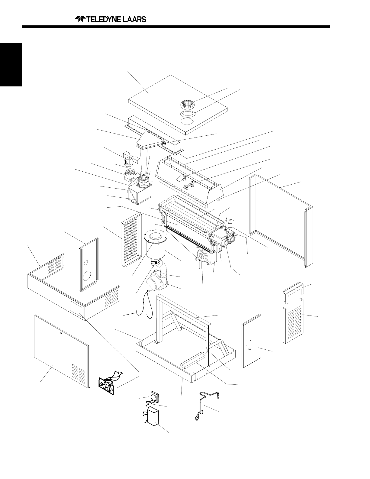
HI-E2™, Manufactured from 1997
12
Heaters
42
/Jandy Products
1999 Products and Parts Catalog
58
57
41
88
85-86
40
33,34
4
6
31
35
10
36
13
39
56
87
16
49
38
37
55
53,54
52
51
50
14
17
70-72
18-23
15
24-29
43
44
47
67,68
45
46
3
30
9
89
1
77-83
7
63
66
64
11
65
2
74-76
8
5
69
60-62
Page 9

/Jandy Products
1999 Products and Parts Catalog
Page 11
Hi-E2
Key Model ORDER
No. Description No. PART NO:
Limestone Gravel (Condensate Neutralizer) All R0306200
Combustion Air Filter All R0308000
1 Base Panel 220-350 R0301703,05
2 Frame Support Assembly 220-350 R0301503,05
3 Back Panel 220-350 R0300703,05
4 Left Side Panel All R0300500
5 Right Side Panel All R0300800
6 Temperature Control Panel Assembly All R0301603,05
7 Door 220-350 R0301103,05
8 Inlet/Outlet Header Panel All R0301000
9 Right Top Side Panel All R0300900
10 Return Header Panel All R0300600
11 Front Kick Panel 250-350 R0213403,05
12 T op Panel 220-350 R0300103,05
Jacket Hardware Kit
Internal Hardware Kit
13 Heat Exchanger Assembly, Complete 220-350 R0303803,05
14 Heat Exchanger Tube Assembly 220-350 R0304103,05
15 Inlet/Outlet Header All R0303900
16 Return Header All R0304000
17 Gasket, Header All R0304300
18 By-Pass Valve Assembly All R0304400
19 Flow Control Cap All 10557400
20 By-Pass Valve Gasket All R0011400
21 By-Pass Valve Spring All R0304500
22 By-Pass Valve Rod All R0304900
23 By-Pass Valve Disk All R0011500
24 Flange & Gasket Assembly, 2" (Set of 2) All R0055000
25 Flange, 2" All 10573500
26 Flange Gasket, 2" All S0078000
27 Flange Sleeve, 2" All S0078200
28 Flange Bolt All F0031700
29 Flange Gasket 1 1/2 - 2" All S0078100
30 Pressure Relief Valve, 75 PSI All R0040400
(Requires field supplied 3/4 NPT x 3" brass nipple)
Heat Exchanger Hardware Kit
Inlet/Outlet Header Hardware Kit
Return Header Hardware Kit
31 Gas Valve All R0200100
32 Anti-Rotation Bracket (Not Shown) All R0309900
33 Orifice Holder All R0320000
34 Gas Orifice, NAT 220-350 R0309303,05
34 Gas Orifice, LPG 220-350 R0309403,05
35 Combustion Air Filter Assembly All R0306400
36 Combustion Air Filter All R0308000
37 Venturi Inlet 220-350 R0320303,05
38 Venturi O-ring All R0320400
39 Venturi Plenum All R0320500
40 Venturi/Tailpipe Gasket All R0320600
41 Mixing Chamber/Tailpipe Assembly All R0307300
42 Mixing Chamber/Burner Gasket All R0320800
43 Burner Assembly 220-350 R0305903,05
44 Burner/Combustion Chamber Gasket 220-350 R0305803,05
45 Combustion Chamber Assembly 220-350 R0305103,05
46 Refractory Tile Set 220-350 R0305303,05
47 Sight Glass Assembly All R0305400
48 Combustion Chamber Strip Set 220-350 R0213103,05
49 Combustion Chamber/Collector Gasket 220-350 R0305703,05
Venturi Hardware Kit
Mixing Chamber Hardware Kit
Burner Hardware Kit
MAINTENANCE AND SERVICE COMPONENTS
JACKET ASSEMBLY
(Note 1)
(Note 1)
WA TER SYSTEM
(Note 1)
(Note 1)
(Note 1)
COMBUSTION SYSTEM ASSEMBLY
(Not Shown)
(Note 1)
(Note 1)
(Note 1)
All R0302100
All R0302500
220-350 R0319103,05
All R0319300
All R0319200
All R0322200
All R0322100
220-350 R0319403,05
Key Model ORDER
No. Description No. PART NO:
50 Collector 220-350 R0303203,05
51 Blower/Collector Gasket All R0308700
52 Combustion Blower All R0308200
53 Blower/Vent Duct Sleeve All R0308600
54 Blower/ Vent Duct Clamp All R0308800
55 Vent Duct Assembly All R0303100
56 Vent Duct/Heater Top Gasket or
Heater Top/Indoor Vent Collar Gasket All R0309100
57 Heater Top/Outdoor Exhaust Grille Gasket All R0309500
58 Outdoor Exhaust Grille All R0308400
59 Indoor Vent Collar (Not Shown) All R0307900
60 Condensate Trap Assembly All R0303300
61 Limestone Gravel All R0306200
62 Condensate Trap Cover All R0213300
Venturi Hardware Kit
Mixing Chamber Hardware Kit
ELECTRICAL COMPONENTS AND CONTROLS
63 Transformer All R0061100
64 In-Line Fuse Holder Assembly All R0325600
65 Ignition Control All R0202900
66 Wire Harness, Ignition Control All R0302700
67 Igniter Assembly All R0016400
68 Igniter Gasket All R0205300
69 Terminal Block All R0301900
70 High-Limit Switch Set All R0322700
71 High-Limit Switch, 135°F All R0302400
72 High-Limit Switch, 150°F All R0302300
73 High-Limit Switch Wire Harness All R0322600
(Not Shown)
74 Pressure Switch & Syphon Loop Assembly All R0322900
75 Pressure Switch, 2 PSI All R0013200
76 Pressure Switch Siphon Loop All R0307800
77 Temperature Control Assy, Electronic All R0011700
78 T emperature Sensor (Not Shown) All R001 1800
79 Temperature Sensor Gasket All E0116400
80 Temperature Sensor Plastic Sleeve All 10444900
81 T emperature Control Knob All R0010700
82 Pool/Spa Selecter Knob All R0099900
83 "T emp-Lok" Disc All 10583100
84 Temperature Sensor Retainer Clip All 10716701
(Not Shown)
85 Differential Pressure Switch All R0302000
86 Differential Pressure Switch Bracket All R0302200
87 Exhaust Vent Limit Switch All R0309000
88 Burner High Limit Switch All R0319700
89 Combustion Blower Wire Harness All R0308100
OPTIONAL COMPONENTS
Touch Up Spray Paint All X0021 100
High T emperature Silicone Sealant A ll R0322800
Notes:
1. All hardware sets contain all pieces necessary for assembly, including
gaskets. Not shown. Gaskets and hardware are included in all kits
that involve the removal of a gasket as part of the procedure to
replace a part.
EXHAUST ASSEMBL Y
(Note 1)
(Note 1)
All R0322200
All R0322100
Heaters
Page 10
Page 12
/Jandy Products
Mighty Therm AP Commercial Pool Heaters
Part No. Input Output
AP-500 500,000 BTU/Hr 405,000 BTU/Hr
AP-600 600,000 BTU/Hr 486,000 BTU/Hr
Heaters
AP-715 715,000 BTU/Hr 580,000 BTU/Hr
AP-850 850,000 BTU/Hr 690,000 BTU/Hr
AP-1010 1,010,000 BTU/Hr 820,000 BTU/Hr
AP-1200 1,200,000 BTU/Hr 972,000 BTU/Hr
AP-1430 1,430,000 BTU/Hr 1,160,000 BTU/Hr
AP-1670 1,670,000 BTU/Hr 1,353,000 BTU/Hr
AP-1825 1,825,000 BTU/Hr 1,480,000 BTU/Hr
AP-2000 2,000,000 BTU/Hr 1,639,000 BTU/Hr *
AP-2200 2,200,000 BTU/Hr 1,786,000 BTU/Hr **
AP-2450 2,450,000 BTU/Hr 2,009,000 BTU/Hr *
AP-2800 2,800,000 BTU/Hr 2,223,000 BTU/Hr **
AP-3050 3,050,000 BTU/Hr 2,501,000 BTU/Hr *
AP-3200 3,200,000 BTU/Hr 2,552,000 BTU/Hr **
AP-3500 3,500,000 BTU/Hr 2,870,000 BTU/Hr *
AP-3600 3,600,000 BTU/Hr 2,951,000 BTU/Hr **
AP-4000 4,000,000 BTU/Hr 3,281,000 BTU/Hr **
AP-4050 4,050,000 BTU/Hr 3,321,000 BTU/Hr *
AP-4500 4,500,000 BTU/Hr 3,645,000 BTU/Hr **
AP-5000 5,000,000 BTU/Hr 4,100,000 BTU/Hr *
1999 Products and Parts Catalog
* Indoor model only .
** Outdoor Model Only
Options Include:
Indoor / Outdoor- Indoor units include built in draft diverter. Outdoor units do not require a vent cap.
Natural Gas / Propane- Natural gas units come standard with electronic ignition (SYS 9). Propane
units come standard with electroinc pilot supervision and standing pilot (SYS 16).
Heat Exchanger - Glass/Copper; Glass/Cu-Ni; Bronze/Copper; Bronze/Cu-Ni.
Local Code Requirements.
For more information:
Telephone: Main: (415)382-8220 Order Fax: (800)526-3928
Customer Service: Ext. 245 Warranty/Service: Ext. 260 Literature Requests: Ext. 237
Pool Systems Address: 21 Pimentel Ct., Novato, CA 94949 Mailing Address: P .O. Box 6101, Novato, CA 94948-6101
Web Address: http://www.jandy.com/
International: 480 S. Service Rd. West, Oakville, Ontario, Canada L6K 2H4 (905)844-8233 voice (905)844-2635 fax
Page 11

/Jandy Products
1999 Products and Parts Catalog
Telstar™
This above ground pool and spa heater is a uniquely designed, gas fired
50,000 BTU/hr. heater , engineered for energy efficiency and reliability . It
has several features, including choice of low gas consumption standing
pilot or an electronic ignition, compact design for either free standing or
skid mounting application, conveniently located controls, and reliable 24Volt Control System. Other features include an ef ficient, one-piece
cupro-nickle Heat Exchanger/Combustion Chamber Assembly , standard
bronze header and water connection flanges, universal flange coupling,
internal field wiring compartment, and a built in by-pass for flows up to 80
GPM. The T elstar™ is also listed as a Gas-Fired Spa Heater by Underwriters Laboratories and meets the requirements of U.L. Standard 1563
for Spa Equipment Assemblies. The T elstar™ design is certified by the
American Gas Association Laboratories under ANSI Z21. 56 for gasfired pool heaters.
Model # Ignition Thermostat
Page 13
Heaters
50,000 BTU Input, Natural Gas, Bronze Headers
TGT50AN Millivolt Single
50,000 BTU Input, Propane Gas, Bronze Headers
TGT50AR Millivolt Single
50,000 BTU Input, Natural Gas, Bronze Headers
TGS50AN Electronic Single
For more information:
T elephone: Main: (415)382-8220 Order Fax: (800)526-3928
Customer Service: Ext. 245 Warranty/Service: Ext. 260 Literature Requests: Ext. 237
Pool Systems Address: 21 Pimentel Ct., Novato, CA 94949 Mailing Address: P .O. Box 6101, Novato, CA 94948-6101
Web Address: http://www.jandy.com/
International: 480 S. Service Rd. West, Oakville, Ontario, Canada L6K 2H4 (905)844-8233 voice (905)844-2635 fax
Page 12
Page 14
/Jandy Products
1999 Products and Parts Catalog
TELSTAR™ (SPARK IGNITION) Spa Heaters — TGS-50 -TGS-55 - TRS-55
TELSTAR™ (STANDING PILOT) Spa Heaters — TGT-50 - TGT-55 - TRT-55
Key
No.
Heaters
55 Top Plate
(Indoors)
59 Top Plate
74 Top Panel
(Outdoors)
54 Draft Diverter
Hood (Indoors)
73 Cowling
2 Thermocouple
53 Draft Diverter
Assembly
(Indoors)
58 Wind Deflector
Plate (Outdoors)
57 Sleeve, 6"
Diamter
(Outdoors)
56 Sleeve, 4"
Diameter
(Outdoors)
80 Spacer
78, 79 Spacer
Sleeve
72 Cowling, Lower
70 Flue Collector
71 Heater Top
20 Pressure Switch
38 Siphon Loop
46 Nut
78, 79 Spacer
76 Insulation, Flue
Collector T op
70 Flue Collector
45 Sleeve
44 Compression
Fitting
42 Retainer, Flow
Control Rod
39 Rod, Flow
Control
40 By-Pass Valve
Spring
43 Compression
Fitting
41 By-Pass Valve
21 Limit Switch
65 Housing
67 Sight Glass
66 Bezel
68 Lower Wrap
18 Terminal Strip
33 Thermostat
Knob
TGT
TGS
Key
No.
69 Top Assembly
22 Limit Switch
27 Retainer Clip
77 Insulation and
Retainer
75 Rating Plate
Bracket
47 Heat Exchanger
3, 4 Pilot Burner
1 Pilot burner
13, 14 Pilot Bracket
9, 10 Orifices
1, 12 Burner Assembly
26 High Voltage
Ignitor Lead
Assembly
5 Pilot Tubing
6, 8 Gas Valve
7 Gas Valve
60 Rear Panel
63 Bushing
51 Flange Bolts
50 Plastic Sleeve
48 Flange
49 Packing Collar
52 Drain Plug
34 Plate, Junction
Box
28 Ground Wire
15 Transformer
62 Grommet
37 In/Out Casting
61 Base
35 Sleeve,
Temperature
Control
30 “O” Ring
19 Temperature
Control
32 TEMP-LOK™
24 Indicator Light
17 Toggle Switch
29 Mounting Plate
23 Time Delay
Relay
25 Ignition Control
26 High Voltage
Ignitor Lead
Assembly
Page 13

/Jandy Products
1999 Products and Parts Catalog
Page 15
TELSTAR™ (SPARK IGNITION) Spa Heaters — TGS-50 -TGS-55 - TRS-55
TELSTAR™ (STANDING PILOT) Spa Heaters — TGT-50 - TGT-55 - TRT-55
Heaters
Key ORDER PART NO
No. Description TGT TG S
1 Pilot Burner, NA T R0013700 ———
2 Thermocouple R0014000 ———
3 Pilot Burner, NA T ——— R0013800
4 Pilot Burner, LPG R0013900 ———
5 Tube, Pilot Gas, Formed (50) 10528700 10490500
Tube, Pilot Gas, Formed (55) 10489800 10490500
6 Gas Valve, NAT R0038200 ———
7 Gas Valve, NAT ——— R0039200
8 Gas Valve, LPG R0046900 ———
9 Main Burner Orifices, NAT L0053100 L0053100
10 Main Burner Orifices, LPG L0054100 ———
11 Burner Assembly, NAT
12 Burner Assembly, LPG
13 Pilot/Hx Bracket, NAT 10489501 10489502
14 Pilot/Hx Bracket, LPG 10489501 ———
19 Temperature Control R0318800 R0318800
29 Temperature Control Mounting Plate Assy 10491000 10491000
30 “O” Ring E0036300 E0036300
31 Temperature Control Logo H0078300 H0078300
32 "Temp-Lok" Stop Plate 10456700 10456700
35 Protector Sleeve, Bulb 10444900 10444900
15 Transformer (115-230/24V) R0061100 R0061100
16 Fusible Link R0012200 ———
17 On-Off Switch R0014400 R0014400
18 Terminal Strip E0098500 E0098500
20 Pressure Switch, 2 PSI R0014500 R0014500
20 Pressure Switch, 1 PSI R0011300 R0011300
20A Pressure Switch, 1-10 PSI R0015500 R0015500
38 Siphon Loop Tube 10492300 10492300
21 High-Limit Switch, 120°F (50) R0014600 R0014600
22 High-LimitSwitch, 150°F (50) R0014700 R0014700
21 High-Limit Switch, 120°F (55) 10513000 ———
22 High-Limit Switch, 150°F (55) 10512900 ———
23 Time Delay Relay (50) R0014800 R0014800
23 Lockout Relay (55) ——— E0086500
24 Heating Indicator Light, Red E0081700 E0081700
25 Ignition Control
26 High Voltage Lead Assembly ——— 10449517
26 High Voltage Lead Assembly ——— 10449510
27 Retainer Clip, 150F F0037700 F0037700
28 Ground Wire Assembly 10497500 10497500
33 Thermostat Knob R0010700 R0010700
34 Junction Box Plate 10496300 10496300
Wire Harness (55) R0011100 R0011200
37 Inlet/Outlet Header, Bronze 10489200 10489200
By-Pass Assembly R0020600 R0020600
39 By-Pass Valve Rod S0074300 S0074300
41 By-Pass Valve Disk S0074200 S0074200
42 By-Pass Valve Rod Retainer S0008700 S0008700
40 By-Pass Valve Spring S0061200 S0061200
43 Compression Fitting, 3/16" Tube x 1/8" NPT P0019701 P0019701
PILOT GAS SYSTEM
MAIN GAS SYSTEM
(Note 1,2)
(Note 1,2)
ELECTRICAL SYSTEM
(Note 4)
WA TER SYSTEM
L0054400 L0054400
L0054400 L0054400
——— R0011900
Key ORDER PART NO
No. Description TGT TG S
44 Compression Fitting, 5/8" Tube x 1/2" NPT P0070000 P0070000
45 Compressiton Fitting Sleeve, 5/8" Tube P0070100 P0070100
46 Compression Fitting Nut, 5/8" Tube P0070200 P0070200
47 Heat Exchanger Assembly S0072400 S0072400
Flange & Gasket Assembly R0015000 R0015000
48 Flange, Bronze, 1 1/2" 10489400 10489400
49 Flange Gasket, 1 1/2" S0053100 S0053100
50 Flange Sleeve, 1 1/2" S0028000 S0028000
51 Flange Bolts, 3/8" x 16 1 1/4" F0009500 F0009500
51 Flange Bolts, 3/8" - 16- 1 1/2"
52 Drain Plug P0026800 P0026800
VENT SYSTEM
53 Draft Diverter Assembly (Indoors) D0016800 D0016800
54 Draft Diverter Hood/Wind Deflector Plate Assy 10499500 10499500
(Indoors)
55 Top Plate (Indoors) 10488900 10488900
56 Sleeve, 4" Diameter (Outdoors) 10496900 10496900
57 Sleeve, 6" Diameter (Outdoors) 10497000 10497000
58 Wind Deflector Plate (Outdoors) 10497100 10497100
59 Top Plate (Outdoors) 10488800 10488800
60 Rear Panel 10488300 10488300
61 Base 10493200 10493200
62 Slitted Grommet, 1 1/2" F0038800 F0038800
63 Nylon Bushing S0064900 S0064900
64 Control Panel Weldment 10494200 10494200
65 Housing Weldment 10495900 10495900
66 Bezel S0072100 S0072100
67 Sight Glass F0038700 F0038700
68 Lower Wrap 10496200 10496200
69 Top Assembly 10487700 10487700
70 Flue Collector 10487300 10487300
71 Heater Top 10489000 10489000
72 Cowling, Lower 10488600 10488600
73 Cowling, Weldment 10496000 10496000
74 T op Panel 10487500 10487500
75 Rating Plate Bracket 10489600 10489600
76 Insulation, Flue Collector Top T0022100 T0022100
77 Insulation, Heat Exchanger (Not Shown) T0022500 T0022500
78 Spacer Sleeve, 5/16" O.D. x 5/32" (4 Required) F0037301 F0037301
79 Spacer Sleeve, 5/16" O.D. x 2 7/32" (4 Reqd) F0037302 F0037302
80 Spacer, Threaded, 5/16" Hex x 2 21/32" F0037800 F0037800
(4 Required)
Notes:
1. Main Burner Orifices not included.
2. For altitutdes higher than 2000 ft. above sea level, consult factory for
orifice size.
3. Key Nos. 49 & 50 available in Assembly R0021100.
4. For heaters with H/W Ignition Controls S86F or S86E only.
(Note 3)
(50) F0016700 F0016700
JACKET COMPONENTS
For more information:
T elephone: Main: (415)382-8220 Order Fax: (800)526-3928
Customer Service: Ext. 245 Warranty/Service: Ext. 260 Literature Requests: Ext. 237
Pool Systems Address: 21 Pimentel Ct., Novato, CA 94949 Mailing Address: P .O. Box 6101, Novato, CA 94948-6101
Web Address: http://www.jandy.com/
International: 480 S. Service Rd. West, Oakville, Ontario, Canada L6K 2H4 (905)844-8233 voice (905)844-2635 fax
Page 14

Page 16
/Jandy Products
1999 Products and Parts Catalog
Elektra Star™
This compact, dependable electric heater is specifically designed for
above ground spas and hot tubs. It features universal flange coupling, and a choice of either 5.5 kW or 1 1 kW models. Both models
operate on 240 volts, 60 Hz power, at 25 and 50 amps respectively .
Heaters
A thermostat with T emp-Lok™ device to provides a convenient
reminder for setting, and an on/off switch for convenience and safety .
Other features include a power indicator lamp, stainless steel tank,
and snap-action pressure switch. The Electra Star™ is UL listed
under Standard 1261 for indoor/outdoor installation.
Model # Ignition Thermostat Ctn. Weight
Max Input 5.5 kW , Electric
TE55 Electronic Single 28
Max Input 1 1.0 kW, Electric
TE110 Electronic Single 28
Key ORDER
No. Description P ART NO:
1. On/Off Switch R0099800
2. Front Panel R0150300
3. Light and Lens R0150100
4. Wiring Harness R0150400
5. High Limit 150°F R0045200
6. T emperature Control R0150500
7. Base and Jacket Assembly R0151100
8. Contactor R0151000
9. Coupling Assembly R0150900
Key ORDER
No. Description PART NO:
10. Time Delay Relay w/Strap R0013500
11. Heating Element, 5.5 KW (TE-55) R0150700
Heating Element, 11.0 KW (TE-110) R0150800
12. Pressure Switch, 2 PSI R0150600
Pressure Switch, 10 PSI R0015500
Pressure Switch, 1 PSI R0011300
13. "T emp-Lok" Stop Plate R0150200
14. T emperature Control Knob R0150000
Hardware Kit (Not shown) R0151200
Page 15

/Jandy Products
1999 Products and Parts Catalog
Page 17
XL-3 Oil Fired Pool & Spa Heaters
The XL-3 oil fired heater safely , cleanly and automatically heats your
pool. Featuring safety controls that automatically guard against flame
failure and excessive variations in temperature and water flow . The
precise temperature controls and UL-listed oil burner assure economic and quiet operation.
Model # Ignition Thermostat Ctn. Weight
230,000 BTU Input, Oil-Fired, Stainless Steel Headers
DP2000 110V Single 285
315,000 BTU Input, Oil-Fired, Stainless Steel Headers
DP3000 110V Single 315
Heaters
For more information:
T elephone: Main: (415)382-8220 Order Fax: (800)526-3928
Customer Service: Ext. 245 Warranty/Service: Ext. 260 Literature Requests: Ext. 237
Pool Systems Address: 21 Pimentel Ct., Novato, CA 94949 Mailing Address: P .O. Box 6101, Novato, CA 94948-6101
Web Address: http://www.jandy.com/
International: 480 S. Service Rd. West, Oakville, Ontario, Canada L6K 2H4 (905)844-8233 voice (905)844-2635 fax
Page 16

Page 18
/Jandy Products
XL-2 Model DP Oil Fired Heaters
1999 Products and Parts Catalog
Heaters
24
54
27
55
37
25
32
36
30
31
25
63
29
33
29
57
8,9
29
58
18
56
59
60
7
5
64
40
6
10
30
39
42
15
48
19
53
51
52
49
62
26
50
61
1
17
13
23
20
21
22
4
11
43
45
46
44
47
34
12
Page 17

/Jandy Products
1999 Products and Parts Catalog
Page 19
XL-2 Model DP Oil Fired Heaters
Key Model ORDER
No. Description No. PART NO.
FUEL SYSTEMS
1 Oil Burner Assembly 250 L0038700
1 Oil Burner Assembly 350 L0038900
2 Oil Filter (Not Shown) All P0065100
3 Oil Filter Cartridge (Not Shown) All P0065500
4 3/8” Oil Line, Pump to Filter All 10430402
ELECTRICAL SYSTEM
5 Thermostat All R0318800
6 Thermostat Knob All R0010700
7 Thermostat Dial All H0048400
8 Thermostat Cover All 10388300
9 Thermostat Back All 10368000
10 Thermostat Base Plate All 10362000
11 Pressure Switch, 1-10 PSI All R0045400
12 Siphon Loop Cover All 10403400
13 Siphon Loop Assembly All R0057800
14 High-Limit Switch Assembly All R0023200
15 High-Limit Switch, 135°F All R0022700
16 High-Limit Switch, 150°F All R0012700
17 High-Limit Switch Harness (115V) A l l R0057500
18 High-Limit Switch Harness All R0057700
19 High-Limit Switch Cover All 10401100
20 Switch Cover All E0078300
21 ON/OFF Switch All E0078200
22 Oil Burner Harness All R0057600
23 Connector Elbow 90° All P0059800
WATER SYSTEMS
24 Heat Exchanger Assembly, Complete 250 10403601
24 Heat Exchanger Assembly, Complete 350 10403602
25 Heat Exchanger 250 10403501
25 Heat Exchanger 350 10403502
26 Inlet/Outlet Header All 10403700
27 End Cap (1/2” tap) All 10403900
28 End Cap (No tap) All 10406100
29 End Cap (1/4” tap) All 10403800
30 Tee Baffle (5) 250 10387804
30 Tee Baffle (5) 350 10387805
31 End Baffle (2) 250 10387702
31 End Baffle (2) 350 10387703
32 Tube Gaskets (12) All S0063400
34 Grommet (2 Required) All S0098800
35 Brass Plug, 3/4” (1) All P0027000
36 Drain Valve Extension All P0059900
37 Drain Plug, 1/4” (3) All P0026800
38 By-Pass Assembly All R0020600
39 By-Pass Valve Rod All S0074300
40 By-Pass Valve Disc All S0074200
41 By-Pass Valve Rod Retainer All S0008700
42 By-Pass Valve Spring 250 S0061100
42 By-Pass Valve Spring 350 S0061000
43 Flange & Gasket Assembly All R0031900
44 Flange, 1 1/2" All 10309200
45 Flange Gasket, 1 1/2" All S0053100
46 Flange Sleeve, 1 1/2" All S0028000
47 Flange Bolt All F0031700
48 Gasket All S0065300
Heaters
Key Model ORDER
No. Description No. PART NO.
FIRE BOX & JACKET COMPONENTS
49 Burner Tube Gasket All N0006600
50 Burner Support Bracket All 10392000
51 Burner Compartment Door 250 10412203
51 Burner Compartment Door 350 10412204
52 Fire Box Plug All T0020700
53 Fire Box Cover Plate All 10425800
54 Gap Spacer (Return) All 10401000
55 Flue Collector Assemby All 10406301
55 Flue Collector Assemby All 10406302
56 Flue Top Assembly 250 10405001
56 Flue Top Assembly 350 10405002
57 Inner Stack All 10390000
58 Flue Collector Shield 250 10404501
58 Flue Collector Shield 350 10405002
59 Vent Blade (10) All 10319300
60 Gap Spacer (In/Out) All 10400900
61 Hold Down Clip All 10401200
62 Fire Box 250 T0020500
62 Fire Box 350 T0020600
63 Fire Box Cover (2) 250 10400801
63 Fire Box Cover (2) 350 10400802
OIL BURNER PARTS & COMPONENTS (Not Shown)
Air Tube Screw All F0004300
Pilot Bracket Screw All F0031300
End Air Shutter All N0000200
Bulk Air Band All N0000300
Air Tube Gasket All N0000800
Motor, 1/7 H.P. , 3450 RPM All N0001000
Blower Wheel 4- 1/4” x 3- 7/16” All N0001400
Flexible Coupling All N0001500
Fuel Unit, Two Stage All R0140100
Pump Outlet Fitting All N0002000
Connector Tube Assembly All N0002200
Ignition Transformer All R0140200
Contact Spring Terminals All N0002600
Nozzle, Monarch 1.75 All N0002800
Air Tube Combination All N0002900
Nozzle Line Electrode Assembly All N0003100
Electrode Clamp All N0003500
Electrode Rod & Tip Al l N0004000
Burner Head & Screws All N0004500
Burner Head All N0004700
Delavan Nozzle, 2.50 350 N0005800
Delavan Nozzle, 1.75 250 N0006500
Primary Control All R0140300
Honeywell Cad Cell All N0006100
By-Pass Plug All N0007000
By-Pass Plug All N0007100
1/8” Burner Head Plug All P0026100
1/4” Burner Head Plug All P0026800
OPTIONAL EQUIPMENT
64 Pressure Relief Valve, 3/4" NPT, 75 PSI All R0040400
Chimney Cap - 9" (Not Shown) All D0014900
For more information:
T elephone: Main: (415)382-8220 Order Fax: (800)526-3928
Customer Service: Ext. 245 Warranty/Service: Ext. 260 Literature Requests: Ext. 237
Pool Systems Address: 21 Pimentel Ct., Novato, CA 94949 Mailing Address: P .O. Box 6101, Novato, CA 94948-6101
Web Address: http://www.jandy.com/
International: 480 S. Service Rd. West, Oakville, Ontario, Canada L6K 2H4 (905)844-8233 voice (905)844-2635 fax
Page 18

Page 20
/Jandy Products
1999 Products and Parts Catalog
MARK V Pool Heaters — DM-125, 175, 250, 325 and 400
Manufactured from 1975-1984
Key
No.
36 Outdoor Vent Cap
Heaters
37 Indoor Draft Hood
34 Indoor Stack Top
75 Flue Collector,
Upper Half
Stack Top Low Profile
Key
No.
33 Grate Top
Assembly
75 Flue Collector,
Upper Half
73 Jacket Gap Spacer
74 Vent Blade
76 Flue Collector,
Lower Half
64 Baffle Retainer
62 Heat Exchanger
Tube Assembly
22 Thermostat Box
Assembly
45 Header Gasket
63 Tee-Baffle
54 Drain Plug
65 Heat Exchanger
Support Clip
Wind Deflector,
Lower Half
54 Drain Plug
40 Return Header
41,42Header bolt
Assembly
69 Front/Rear
Tile Cover
26 Siphon Loop
Assembly
25 Pressure Switch
51,52Grommets for
Drain Plug
68 Front and Rear Tile
66 Insulation,
Fiberglass
67 Side Tile
13 Burner, Main with
Pilot Bracket
71 Door with
Latch
11 Gas Valve Assembly
3 Pilot Tubing
12 Gas Orifice
6 Visoflame Tubing
15 Burner Manifold
5 Lighter Tube Orifice
21 Thermostat Label
16 Temperature
Control
19 Thermostat Knob
20 On-Off Switch
24 Temperature
Sensor Retainer
57,60By-Pass Valve
Rod Retainer
58 By-Pass Valve
Rod
61 By-Pass Valve
Spring
59 By-Pass Valve
Disc
56 Brass Plug
47 Flange, 1 1/2"
50 Flange Bolt
48,49 Flange Gasket
Flange Sleeve
High-Limit
28,29
Switches
23 Wire Harness
39 Inlet/Outlet Header
30,32 High-Limit Switch
Clip, Cover
41 Header Bolt
Assembly
54 Drain Plug
51 Grommet for Drain
Plug
53 Hole Plug
70 Side Tile Cover
72 Jacket Assembly
14 Burner, Main
9 Burner Tray
Assembly
10 Burner Tray,
Shelf Only
1 Pilot Burner
Generator
Assembly
4 Visoflame
Lighter Tube
T ouch-up Paint
Page 19

/Jandy Products
1999 Products and Parts Catalog
Page 21
MARK V Pool Heaters — DM-125, 175, 250, 325 and 400
Key Model ORDER
No. Description No. PART NO:
1 Pilot Burner/Gen. Assembly, NAT
1 Pilot Burner/Gen. Assembly, LPG
2 Pilot Generator All R0025500
3 Pilot Tubing All R0037000
4 Visoflame Lighter Tube All W0016200
5 Lighter Tube Orifice, NAT All W0018800
5 Lighter Tube Orifice, LPG All W0018900
6 Visoflame Tubing All 10369600
7 Lighter Valve, Visoflame, with Orifice All N/A
8 Lighter Valve Tee Assembly, Visoflame All N/A
9 Burner Tray Assembly, NAT
9 Burner Tray Assembly, LPG
10 Burner Tray, Shelf Only 125-400 R0317001-05
11 Gas Valve Assembly, NAT
11 Gas Valve Assembly, LPG
12 Gas Orifice, NAT
12 Gas Orifice, LPG
13 Burner, Main with Pilot Bracket All L0033400
14 Burner, Main All L0005500
15 Burner Manifold (Note 9)
16 Temperature Control All R0318800
17 "O" Ring, Temp Control Bulb All E0036300
18 Protector Sleeve, Bulb All 10444900
19 Thermostat Knob, Black All R0010700
20 On-Off Switch
21 Thermostat Label All H0048400
22 Thermostat Box Assembly
23 Wire Harness
23 Wire Harness
24 Temperature Sensor Retainer All 10447300
25 Pressure Switch, 2 PSI
25 Pressure Switch, 1 PSI
25 Pressure Switch, 3 PSI
26 Siphon Loop Assembly
27 High-Limit Switch Assembly All R0023200
28 High-Limit Switch, 135° F All R0022700
29 High-Limit Switch, 150° F All R0023000
30 High-Limit Switch Retainer Clip All S0099000
31 High-Limit Switch Retainer Boot All S0098900
32 High-Limit Switch Cover All 10418300
33 Grate Top Assembly N/ A
34 Indoor Stack Top N/A
35 Flue Assembly N/A
36 Outdoor Vent Cap 125-400 10561501-05
37 Indoor Drafthood 125-400 10561401-05
38 Clip All 10211000
39 Inlet/Outlet Header, 1 1/2"
40 Return Header
41 Header Bolt Assembly All R0057000
42 Bolt for Headers, 2 1/2" All F0046100
43 Washer for Headers All F0011100
44 Nut for Headers All F0003100
45 Header Gasket Assembly (Set of 18) All R0050800
46 Flange & Gasket Assembly, 1 1/2"
47 Flange, 1 1/2" All 10309200
48 Flange Gasket, 1 1/2" All S0053100
49 Flange Sleeve, 1 1/2" All S0028000
50 Flange Bolt All F0031700
PILOT GAS SYSTEM
MAIN GAS SYSTEM
(Note 1)
(Note 1)
ELECTRICAL SYSTEM
(Note 2)
(Note 6)
(Note 6)
(Note 7)
(Note 7)
(Note 7)
(Note 7)
WA TER SYSTEM
(Note 8)
(Note 4)
(Note 4)
(Note 1)
(Note 1)
(Note 4)
(Note 4)
(Note 4)
VENT SYSTEM
(Note 8)
(Note 5)
All R0027500
All R0027600
125-400 10601601-05
125-400 10601701-05
All R0027700
All R0027800
All L0032200
All L0032900
All R0094100
All R0057900
All R0023800
All R0023900
All R0013200
All R0011300
All R0013000
All R0057800
All R0056100
All R0056700
All R0031900
Key Model ORDER
No. Description No. PART NO:
51 Grommet for Drain Plug All S0098800
52 Grommet for Drain Plug All R0316300
53 Hole Plug A ll S0098700
54 Drain Plug
55 Drain Plug Bushing All P0018500
56 Brass Plug, 3/4" All P0027000
57 By-Pass Assembly All R0020600
58 By-Pass Valve Rod All S0074300
59 By-Pass Valve Disc All S0074200
60 By-Pass Valve Rod Retainer All S0008700
62 Heat Exchanger Tube Assembly
63 Heat Exchanger Tee-Baffle All 10308501-05
64 Baffle Retainer All S0057200
65 Heat Exchanger Support Clip All 10457000
66 Insulation, Fiberglass
67 Side Tile, 16 1/2" x 18 13/16" All T0003400
68 Front/Rear Tile, 21" x 9 1/8" 125 T0003900
68 Front/Rear Tile, 21" x 12 1/8" 175 T0003500
68 Front/Rear Tile, 21" x 16 5/8" 250 T0003600
68 Front/Rear Tile, 21" x 20 7/8" 325 T0003700
68 Front/Rear Tile, 21" x 25 7/8" 400 T0003800
69 Front/Rear Tile Cover 125-400 10314901-05
70 Side Tile Cover All 10167300
71 Door with Latch N/A
72 Jacket Assembly, Less Top Assembly N/A
73 Jacket Gap Spacer N/A
74 Vent Blade Al l 10319300
75 Flue Collector, Upper Half N/A
76 Flue Collector, Lower Half N/A
OPTIONAL EQUIPMENT
Touch Up Spray Paint All X0006000
Notes:
1. For altitudes higher than 2000 ft. above sea level, see appendix.
2. Installed on models with Serial Nos. B7629498 and above.
3. Bolts, nuts and washers are not supplied with heat exchanger. Order
assembly R0057000.
4. Current available substitute, includes accessory parts.
5. Two included in assembly
6. Heaters with Serial Nos. 7508988 and below, use assembly R0023800
(black/white). Heaters with Serial Nos. 7508989 and above, use assembly
R0023900 (white).
7. Parts assembly R0020900 required to adapt to Pressure Switch connection.
8. Includes necessary gaskets and hardware.
9. See Appendix
(Note 4)
FIREBOX COMPONENTS
(Sold by ft.)
JACKET COMPONENTS
(Note 3)
Heaters
All P0026800
125-400 10308201-05
All T0002000
Page 20

Page 22
/Jandy Products
1999 Products and Parts Catalog
MARK V Pool Heaters — DR-125, 175, 250, 325 and 400
Manufactured from 1975-1984
Key
No.
38 Outdoor Vent Cap
Heaters
39 Indoor Draft Cap
40 Clip
36 Indoor Stacktop
76 Flue Collector,
Upper Half
64 Heat Exchanger Baffle
47 Header Gasket
Assembly
55 Drain Plug
66 Heat Exchanger
Support Clip
55 Drain Rug
42 Return Header
43,44Header Bolt Assembly
70 Front & Rear Tile Cover
28 Siphon Loop Assembly
52,53Grommets for Drain
Plug
67 Insulation, Fiberglass
68 Side Tile
14 Burner, Main
73 Jacket Assembly,
Less Top Assembly
72 Door with Latch
11 Gas Valve Assembly
3 Pilot Tubing
6 Visoflame Tubing
15 Burner Manifold
12 Gas Orifice
6 Visoflame Tubing
4 Lighter Tube Orifice
7,8 Lighter Valve
5 Visoflame Lighter Tube
1,2 Pilot Burner Generator
Assembly
9 Burner Tray
Assembly
Stack Top Low Profile
Key
No.
35 Grate Top Assembly
76 Flue Collector,
Upper Half
74 Jacket Gap Spacers
75 Vent Blade
77 Flue Collector,
Lower Half
65 Baffle Retainer
63 Heat Exchanger
Tube Assembly
20 On-Off Switch
21 Temperature Control
Cover, Base & Back
25,26 Stop Plate,SafeT Lok
24 Thermostat Dial
16,17T emperature Control
18
21 Thermostat
Base Plate
19 Thermostat Knob,
Black
23 Temperature
Sensor Retainer
58,59By-Pass Valve Rod
61 By-Pass Valve
Rod Retainer
57 Brass Plug
62 By-Pass Valve
Spring
60 By-Pass Valve Disc
48 Flange, 1 1/2"
51 Flange Bolt
49 Flange Gasket
50 Flange Sleeve
29,30
High-Limit Switches
31,33
32 High-Limit Switch
Retainer Clip
41 Inlet/Outlet Header
34 High-Limit Switch
Cover
43,45Header Bolt
Assembly
46
55 Drain Plug
56 Drain Plug Bushing
53 Grommet For Drain
Plug
54 Hole Plug
71 SideTile Cover
27 Pressure Switch
69 Front/Rear Tile
13 Burner Main with Pilot
Bracket
10 Burner Tray, Shelf
Only
Page 21

/Jandy Products
1999 Products and Parts Catalog
Page 23
MARK V Pool Heaters — DR-125, 175, 250, 325 and 400
Key Model ORDER
No. Description No. PART NO:
1 Pilot Burner/Gen. Assembly, NAT
1 Pilot Burner/Gen. Assembly, LPG
2 Pilot Generator only All R0025500
3 Pilot Tubing All R0037000
4 Lighter Tube Orifice, NAT All W0018800
4 Lighter Tube Orifice, LPG All W0018900
5 Visoflame Lighter Tube All W0016200
6 Visoflame Tubing A ll 10369600
7 Lighter Valve, Visoflame, with Orifice N/A
8 Lighter Valve Tee Assembly, Visoflame All W0016400
9 Burner Tray Assembly, NAT
9 Burner Tray Assembly, LPG
10 Burner Tray, Shelf Only 125-400 R0317001-05
11 Gas Valve Assembly, NAT
11 Gas Valve Assembly, LPG
12 Gas Orifice, NAT
12 Gas Orifice, LPG
13 Burner, Main with Pilot Bracket All L0033400
14 Burner, Main All L0005500
15 Burner Manifold
16 Temperature Control All R0318800
17 Protector Sleeve, Bulb All 10444900
18 “O” Ring, T emperature Control Bulb All E0036300
19 Thermostat Knob, Black All R0010700
20 On-Off Switch All R0094100
21 Temperature Control Cover
21 Temperature Control Base
21 Temperature Control Back
22 Wire Harness (not shown) All R0029400
23 Temperature Sensor Retainer All 10447300
24 Thermostat Dial All N/A
25 Stop Plate, Safe-T-Lock All 10436100
26 Stop Plate Screw All F0033300
27 Pressure Switch, 2 PSI
27 Pressure Switch, 1 PSI
27 Pressure Switch, 3 PSI
28 Siphon Loop Assembly
29 High-Limit Switch Assembly All R0023200
30 High-Limit Switch, 135°F All R0022700
31 High-Limit Switch, 150°F All R0023000
32 High-Limit Switch Retainer Clip All 10418400
33 High-Limit Switch Retainer Boot All S0098900
34 High-Limit Switch Cover All 10418300
35 Grate Top Assembly N/ A
36 Indoor Stack Top N/A
37 Flue Assembly N/A
38 Indoor Vent Cap 125-400 10561501-05
39 Outdoor Drafthood 125-400 10561401-05
40 Clip All 10211000
41 Inlet/Outlet Header, 1 1/2"
42 Return Header (Note 6) All R0056700
43 Header Bolt Assembly All R0057000
44 Bolt for Headers, 2 1/2" All F0046100
45 Washer for Headers All F0011100
46 Nut for Headers All F0003100
47 Header Gasket Assembly
Flange & Gasket Assembly, 1 1/2"
48 Flange, 1 1/2" All S0053300
49 Flange Gasket, 1 1/2" All S0053100
50 Flange Sleeve, 1 1/2" All S0028000
51 Flange Bolt All F0031700
PILOT GAS SYSTEM
(Note 5)
MAIN GAS SYSTEM
(Note 1)
(Note 1)
(Note 5)
(Note 5)
(Note 1)
(Note 1)
(Note 2)
ELECTRICAL SYSTEM
(Note 3)
(Note 3)
(Note 3)
(Note 8)
(Note 8)
(Note 8)
(Note 8)
VENT SYSTEM
WA TER SYSTEM
(Note 6)
(Set of 18)
(Note 7)
(Note 5)
All R0027500
All R0027600
125-400 10601601-05
125-400 10601701-05
All R0027700
All R0027800
All L0032200
All L0032900
All 10433100
All 10433000
All 10433200
All R0013200
All R0011300
All R0013000
All R0057800
All R0057200
All R0050800
All R0031900
Key Model ORDER
No. Description No. PART NO:
52 Grommet for Drain Plug All S0098800
53 Grommet for Drain Plug All R0316300
54 Hole Plug A ll S0098700
55 Drain Plug
56 Drain Plug Bushing All P0018500
57 Brass Plug, 3/4" All P0027000
58 By-Pass Assembly All R0020600
59 By-Pass Valve Rod All S0074300
60 By-Pass Valve Disc All S0074200
61 By-Pass Valve Rod Retainer All S0008700
62 By-Pass Valve Spring, White 125 S0061400
62 By-Pass Valve Spring, Red 175 S0061300
62 By-Pass Valve Spring, Blue 250 S0061200
62 By-Pass Valve Spring, Brown 325 S0061100
62 By-Pass Valve Spring, Orange 400 S0061000
63 Heat Exchanger Tube Assembly
64 Heat Exchanger Tee-Baffle 125-400 10308501-05
65 Baffle Retainer All S0057200
66 Heat Exchange Support Clip All 10457000
67 Insulation, Fiberglass
68 Side Tile, 16 1/2" x 18 13/16" All T0003400
69 Front/Rear Tile, 21" x 9 1/8" 125 T0003900
69 Front/Rear Tile, 21" x 12 1/8" 175 T0003500
69 Front/Rear Tile, 21" x 16 5/8" 250 T0003600
69 Front/Rear Tile, 21" x 20 7/8" 325 T0003700
69 Front/Rear Tile, 21" x 25 7/8" 400 T0003800
70 Front and Rear Tile Cover 125-400 10314901-05
71 Side Tile Cover All 10167300
72 Door with Latch N/A
73 Jacket Assembly, Less Top Assembly N/A
74 Jacket Gap Spacers N/A
75 Vent Blade Al l 10319300
76 Flue Collector, Upper Half N/A
77 Flue Collector, Lower half N/A
OPTIONAL EQUIPMENT
Pressure Relief Valve, 3/4" NPT, 75 PSI All R0040400
Touch Up Spray Paint All X0006000
Notes:
1. For altitudes higher than 2000 ft. above sea level, see appendix.
2. See Appendix
3. Current on models manufactured after Serial No. 7824000 and available as
assembly R0055400. Order assembly R0057900 for older DR Models. Key
Nos. 8, 12 and 14 and F0030900 and F0033300 Screws included in
assembly.
4. Order assembly R0057000 for complete set of header bolts.
5. Current available substitute, includes accessory parts.
6. Includes necessary gaskets and hardware.
7. Two included in assembly.
8. Parts assembly R0020900 required to adapt to Pressure Switch connection.
(Note 5)
FIREBOX COMPONENTS
(Sold by ft.)
JACKET COMPONENTS
(Note 4)
Heaters
All P0026800
125-400 10308201-05
All T0002000
Page 22

Page 24
/Jandy Products
XE Pool Heaters — EG-125, 175, 250, 325 and 400
Manufactured from 1984-1989
Note: Original top assemblies are no longer available. The Flue Collector and
Key
No.
Heaters
41 Outdoor Vent Cap
42 Indoor Draft Hood
45 Clip
39 Top Enclosure
84 Flue Collector,
Upper Half
70 Heat Exchanger
Tube Assembly
52 Header Gasket
Assembly
61 Drain Plug
48,49Header Bolt
Assembly
73 Heat Exchanger
Support Clip
47 Return Header
61 Drain Plug
78 Front and Rear Tile
Cover
31 Siphon Loop
Assembly
30 Pressure Switch
58 Grommets for
Drain Plug
74 Insulation,
Fiberglass
24 Wire Harness
21 Bezel, Temp
24A
Control Gasket
14 Temperature Control
18 On-Off Switch
20 Thermostat Dial
Logo
22,23 "Temp Lok"
17 Thermostat Knob
19 Temperature Control
Plate Assembly
9 Valve Assembly
80 Door with Latch
3 Pilot Tubing
13 Burner Manifold
10 Gas Orifice
38 Fusible Link
Assembly
4 Lighter Tube Orifice
5 Visoflame Lighter
Tube
1,2 Pilot Burner
Generator Assembly
7 Burner Tray
Assembly
12 Burner Main
top assemblies must be replaced by the Indoor/Outdoor convertible top and
Flue Collector.
Both items must be replaced at the same time.
Stack Top Low Profile
1999 Products and Parts Catalog
Key
No.
39 Top Enclosure
84 Flue Collector,
Upper Half
82,83 Gap Closures
85 Flue Collector,
Lower Half
72 Baffle Retainer
71 Heat Exchanger
Baffle
15 “O” Ring Temp
Control Bulb
16 Protector Sleeve,
Bulb
46 Inlet/Outlet
Header
63 Brass Plug
64,66By-pass Valve
Disc
65 By-pass
68 By-pass Valve
67 By-pass Valve
69 By-pass Valve
53,54 Flange
57 Flange Bolt
55,56Flange Gasket,
32,34High-Limit Switch,
36
33,36 High-Limit Switch,
35 High-Limit Switch
37 High-Limit Switch
50,51Nut for Headers
61 Drain Plug
59 Grommet for Drain
60 Hole Plug
79 Side Tile Cover
81 Jacket Assembly
76,77 Front and Rear
75 Side Tile
11 Burners Main with
8 Burner Tray,
Valve Rod
Gasket, O Ring
Cap
Spring
Flange Sleeve
150°F
135°F
Retainer Clip
Cover
Plug
Tile
Pilot Bracket
Shelf Only
Page 23

/Jandy Products
1999 Products and Parts Catalog
Page 25
XE Pool Heaters — EG-125, 175, 250, 325 and 400
Key Model ORDER
No. Description No. PART NO.
PILOT GAS SYSTEM
1 Pilot Burner/Gen.Assembly, NAT
1 Pilot Burner/Gen. Assembly, LPG
2 Pilot Generator only All R0025500
3 Pilot Tubing All R0037000
4 Lighter Tube Orifice, NAT All W0018800
4 Lighter Tube Orifice, LPG All W0018900
5 Visoflame Lighter Tube All W0016200
6 Visoflame Tubing All 10369600
7 Burner Tray Assembly, NAT
7 Burner Tray Assembly, LPG
8 Burner Tray, Shelf Only 125-400 R0317001-05
9 Gas Valve Assembly, NAT
9 Gas Valve Assembly, LPG
10 Gas Orifice, NAT
10 Gas Orifice, LPG
11 Burner, Main with Pilot Bracket All 10457200
12 Burner, Main All L0052300
13 Burner Manifold
14 Temperature Control
15 "O” Ring, T emperature Control Bulb All E0036300
16 Protector Sleeve, Bulb All 10444900
17 Thermostat Knob, Black Alll R0010700
18 On-Off Switch All R0094100
19 Temperature Control Plate Assembly All 10456300
20 Thermostat Dial Logo All H0105300
21 Temperature Control Gasket All S0070000
22 "Temp-Lok" Stop Plate All 10456700
23 Stop Plate Screw All F0033300
24 Wire Harness All R0058000
24A Bezel All S0069800
30 Pressure Switch, 2 PSI All R0013200
30 Pressure Switch, 1 PSI All R0011300
30 Pressure Switch, 3 PSI All R0013000
31 Siphon Loop Assembly All R0057800
32 High-Limit Switch Assembly All R0023200
33 High-Limit Switch, 135°F All R0022700
34 High-Limit Switch, 150°F All R0023000
35 High-Limit Switch Retainer Clip All 10418400
36 High-Limit Switch Retainer Boot All S0098900
37 High-Limit Switch Cover All 10418300
38 Fusible Link Assembly
39 Top Enclosure
Flue Collector Assembly
41 Outdoor Vent Cap 125-400 10561501-05
42 Indoor Drafthood 125-400 10561401-05
Flue Transition Ring
Adaptor Plate
45 Clip All 10211000
46 Inlet/Outlet Header, 1 1/2" All R0058400
46 Inlet/Outlet Header, Bronze, 1 1/2" All R0054700
47 Return Header, All R0058300
47 Return Header, Bronze All R0054600
48 Header Bolt Assembly All R0057000
49 Bolt for Headers, 2 1/ 2" All F0046100
50 Washer for Headers All F0011100
51 Nut for Headers All F0003100
52 Header Gasket Assembly (Set of 18) All R0050800
53 Flange & Gasket Assembly 1 1/2"
54 Flange, 1 1/2" All 10309200
55 Flange Gasket, 1 1/2" All S0053100
56 Flange Sleeve, 1 1/2" All S0028000
57 Flange Bolt All F0031700
(Note 7)
(not shown)
MAIN GAS SYSTEM
( Note 1)
(Note 1)
(Note 8)
ELECTRICAL SYSTEM
(Note 8)
(Note 2)
(not shown)
(Note 6)
(Note 6)
(Note 1)
(Note 1)
( Note 6)
(Note 6)
VENT SYSTEM
(Note7) (not shown)
WA TER SYSTEM
(Note 3 & 5)
All R0027500
All R0027600
125-400 10578001-05
125-400 10578101-05
All R0027700
All R0027800
All L0032200
All L0032900
All R0058200
All R0012200
125-400 R0081000 -
R0081400
125-400 10564801-05
125-400 10515501-05
125-400 10535301-05
All R0031900
Key Model ORDER
No. Description No. PART NO:
58 Grommet for Drain Plug All S0098800
59 Grommet for Drain Plug All R0316300
60 Hole Plug All S0098700
61 Drain Plug
62 Drain Plug Bushing All P0018500
63 Brass Plug, 3/4" All P0027000
64 By-Pass Assembly All R0013100
65 By-Pass Valve Rod All S0079800
66 By-Pass Valve Disc All R0011500
67 By-Pass Valve Cap All 10452201
68 By-Pass Valve Gasket, “O” Ring All R0011400
69 By-Pass Valve Spring, White 125,175 S0061400
69 By-Pass Valve Spring, Red 250 S0061300
69 By-Pass Valve Spring, Blue 325 S0061200
69 By-Pass Valve Spring, Brown 400 S0061100
70 Heat Exchanger Tube Assembly 125-400 R0018101-05
71 Heat Exchanger Baffle 125-400 10697401-05
72 Baffle Retainer All S0083900
73 Heat Exchanger Support Clip All 10457000
74 Insulation, Fiberglass
75 Side Tile, 22 5/8" x 16 1/2" All T0021400
76 Front Tile, 18 5/8" x 9 1/8" 125 T0021501
76 Front Tile, 18 5/8" x 12 1/8" 175 T0021502
76 Front Tile, 18 5/8" x 16 5/8" 250 T0021503
76 Front Tile, 18 5/8" x 20 7/8" 325 T0021504
76 Front Tile, 18 5/8" x 25 7/8" 400 T0021505
77 Rear Tile, 22 15/16" x 9 1/8" 125 T0021601
77 Rear Tile, 22 15/16" x 12 1/8" 175 T0021602
77 Rear Tile, 22 15/16" x 16 5/8" 250 T0021603
77 Rear Tile, 22 15/16" x 20 7/8" 325 T0021604
77 Rear Tile, 22 15/16" x 25 7/8" 400 T0021605
78 Front and Rear Tile Cover 125-400 10314901-05
79 Side Tile Cover All 10167300
80 Door with Latch 125-400 10448901-05
81 Jacket Assembly, Less Top Assembly 125-400 10447901-05
82 Gap Closure, In/Out Side All 10448200
83 Gap Closure, Return Side All 10448300
84 Flue Collector, Upper Half N/A
85 Flue Collector, Lower Half N/A
OPTIONAL EQUIPMENT
Pressure Relief Valve, 3/4" NPT, 75 PSI All R0040400
Touch Up Spray Paint All X0016000
Notes:
1. For altitudes higher than 2000 ft. above sea level, see appendix.
2. Heaters with Serial Nos. C8301166 and above.
3. Two included in assembly.
4. Order assembly R0057000 for complete set of bolts.
5. Available in bronze as assembly R0015000.
6. Current available substitute, includes accessory parts.
7. Converts top to indoor/outdoor grate top assembly.
8. See Appendix
(Note 6)
FIREBOX COMPONENTS
(Sold by ft.)
JACKET COMPONENT
Heaters
All P0026800
All T0002000
Page 24

Page 26
/Jandy Products
1999 Products and Parts Catalog
XE (ELECTRONIC) Pool and Spa Heaters —
ES, ES II and EC-125, 175, 250, 325 and 400
Manufactured from 1984-1989
Key
No.
Heaters
44 Outdoor Vent Cap
45 Indoor Draft Hood
48 Clip
42 Top Enclosure
89 Flue Collector,
Upper Half
77 Baffle Retainer
75 Heat Exchanger
Tube Assembly
76 Heat Exchanger
Baffles
56 Header Gasket
50,51Return Header
65 Drain Plug
78 Heat Exchanger
Support Clip
52,53Header Bolt
Assembly
83 Tile,
Front and Rear
Cover
54,55Header Bolt
Assembly
26 Pressure Switch
62 Grommets for
Drain Plug
81,82Front and Rear Tile
79 Insulation,
Fiberglass
12 Wire Harness
15 Temperature Control
16 On-Off Switch
17 Temperature
Control Plate
24,25"T emp Lok"
14,19Thermostat Knob
11 Temperature Control
22,23 Bezel, T emperature
Control Gasket
80 Side Tile
84 Side Tile
Cover
85 Door with Latch
6 Gas Valve
2 Pilot Tubing
10 Burner Manifold
7 Gas Orifice
4 Burner Tray
Assembly
35 Fusible Link Bracket
Stack Top Low Profile
Note: Original top assemblies are no
longer available. The Flue collector and
top assemblies must be replaced by the
Indoor/Outdoor convertible top and Flue
Collector.
replaced at the same time.
Both items must be
Key
No.
T op Enclosure
89 Flue Collector,
Upper Half
87,88 Gap Closures
90 Flue Collector,
Lower Half
27 Siphon Loop
Assembly
18,20“O” Ring
13 Temperature
Sensor
91 Insulation and
Retainer
21 Protector
Sleeve, Bulb
49 Inlet/Outlet
Header
67 Brass Plug
59,60Gasket, Flange
Sleeve
70 By-pass Valve
Disc
68,69 By-pass Valve
Rod
73 By-pass Valve
Gasket
72 By-pass Valve
Cap Bolts
71 By-pass Valve
Cap
74 By-pass Valve
Spring
57,58 Flange
61 Flange Bolt
30,32High-Limit
Switch, 150°F
28,29 High-Limit
32
Switch, 135°F
41 Wire Harness
31 HighLimit Switch
Retainer Clip
33 High-Limit Switch
Cover
66 Drain Plug
62 Grommet For
Drain Plug
64 Hole Plug
86 Jacket
Assembly
36 Transformer
37 Fuse
38 Ignition Control
39 Ignition Control
Wire Harness
40 High Voltage
Lead Assembly
8,9 Burner Main
5 Burner Tray,
Shelf Only
3 Ceramic
Insulator
Assembly
34 Fusible Link
Assembly
1 Pilot Burner/
Electrode
Page 25

/Jandy Products
1999 Products and Parts Catalog
Page 27
XE (ELECTRONIC) Pool and Spa Heaters —
ES, ES ll and EC-125, 175, 250, 325 and 400
Key Model ORDER
No. Description No. PART NO.
1 Pilot Burner/Electrode, NAT All R0061600
2 Pilot Tubing A ll R0037000
3 Ceramic Insulator Assembly All R0011600
4 Burner Tray Assembly, NAT
5 Burner Tray, Shelf Only 125-400 R0317001-05
6 Gas Valve, NAT, 1/2" 125-175 R0039200
6 Gas Valve, NAT, 3/4" 250-400 R0099400
7 Gas Orifice, NAT
8 Burner, Main All L0052300
9 Burner, Main with Pilot Bracket All 10457500
10 Burner Manifold
11 Temperature Control Assy -ES, ES II (Note 10) All R0011700
12 Wire Harness All 10457800
13 T emperature Sensor All R0011800
14 Knob, Single Bar All R0099900
15 Temperature Control Assembly - EC (Note 10) All R0318800
16 On-Off Switch All R0094100
17 T emperature Control Plate All 10456300
18 “O” Ring, T emperature Control Bulb All E0036300
Key Numbers 19 - 25 are for both R117 & R3188:
19 Thermostat Knob, Black All R0010700
20 "O" Ring, Temperature Control Bulb All E01 16400
21 Protector Sleeve, Bulb All 10444900
22 Bezel All S0069800
23 Temperature Control Gasket All S0070000
24 "Temp-Lok" Stop Plate All 10583100
25 Stop Plate Screw All F0033300
26 Pressure Switch, 2 PSI All R0013200
26 Pressure Switch, 1 PSI All R0011300
26 Pressure Switch, 3 PSI All R0013000
27 Siphon Loop Assembly All R0057800
28 High-Limit Switch Assembly All R0023200
29 High-Limit Switch, 135°F All R0022700
30 High-Limit Switch, 150°F All R0023000
31 High-Limit Switch Retainer Clip All 10418400
32 High-Limit Switch Retainer Boot All S0098900
33 High-Limit Switch Cover All 10418300
34 Fusible Link Assembly All R0012200
35 Fusible Link Bracket All 10479900
36 Transformer (115V-230V/24V) All R0061100
37 Fuse Packet, 1.5 Amp. All R0012300
38 Ignition Control
39 Ignition Control Wire Harness - ES, ES II All R0059800
40 High Voltage Lead Assembly All 10449513
40 High Voltage Lead Assembly
41 Wire Harness, Complete
42 Top Enclosure
43 Flue Collector Assembly
44 Outdoor Vent Cap 125-400 10451501-05
45 Indoor Drafthood 125-400 10561401-05
46 Flue Transition Ring
47 Adapter Plate
48 Clip All 10211000
(Note 9)
(not shown)
PILOT GAS SYSTEM
MAIN GAS SYSTEM
(Note 1)
(Note 1)
(Note 10)
ELECTRICAL SYSTEM
(Notes 3,4)
(not shown)
VENT SYSTEM
(Note 9) (not shown)
(not shown)
(Note 8)
125-400 10458301-05
All L0032200
All R0011900
All R0012100
All R0058100
125-400 R0081000-
R0081400
125-400 10564801-05
125-400 10515501-05
125-400 10535301-05
No . Description No. PART NO:
49 Inlet/Outlet Header, 1 1/2" All R0058400
50 Return Header All R0058300
51 Return Header, Bronze A ll R0054600
52 Header Bolt Assembly All R0057000
53 Bolt for Headers, 2 1/2" All F0046100
54 Washer for Headers All F0011100
55 Nut for Headers All F0003100
56 Header Gasket Assembly (Set of 18) All R0050800
57 Flange & Gasket Assembly (Note 5 & 7) All R0031900
58 Flange, 1 1/2" All 10309200
59 Flange Gasket, 1 1/2" All S0053100
60 Flange Sleeve, 1 1/2" All S0028000
61 Flange Bolts, 2" All F0031700
62 Grommet for Drain Plug All R0316300
63 Grommet, Slitted
64 Hole Plug All S0098700
65 Drain Plug
66 Drain Plug Bushing A ll P0018500
67 Brass Plug, 3/4" All P0027000
68 By-Pass Assembly All R0013100
69 By-Pass Valve Rod All S0079800
70 By-Pass Valve Disc All R0011500
71 By-Pass Valve Cap All 10452201
72 By-Pass Valve Cap Bolt All F0041600
73 By-Pass Valve Gasket, “O” Ring All R0011400
74 By-Pass Valve Spring, White 125,175 S0061400
74 By-Pass Valve Spring, Red 250 S0061300
74 By-Pass Valve Spring, Blue 325 S0061200
74 By-Pass Valve Spring, Black 400 S0070100
75 Heat Exchanger Tube Assembly (Note 6) 125-400 R0018101-05
76 Heat Exchanger Baffle
77 Baffle Retainer All S0083900
78 Heat Exchanger Support Clip All 10457000
79 Insulation, Fiberglass (Sold by ft.) All T0002000
80 Side Tile, 22 5/8" x 16 1/2" All T0021400
81 Front Tile, 18 5/8" x 9 1/8" 125 T0021501
81 Front Tile, 18 5/8" x 12 1/8" 175 T0021502
81 Front Tile, 18 5/8" x 16 1/8" 250 T0021503
81 Front Tile, 18 5/8" x 20 7/8" 325 T0021504
81 Front Tile, 18 5/8" x 25 7/8" 400 T0021505
82 Rear Tile, 22 15/16" x 9 1/8" 125 T0021601
82 Rear Tile, 22 15/16" x 12 1/8" 175 T0021602
82 Rear Tile, 22 15/16" x 16 5/8" 250 T0021603
82 Rear Tile, 22 15/16" x 20 7/8" 325 T0021604
82 Rear Tile, 22 15/16" x 25 7/8" 400 T0021605
83 Front and Rear Tile Cover 125-400 10314901-05
84 Side Tile Cover All 10167300
85 Door with Latch 125-400 10448901-05
86 Jacket Assembly, Less Top Assembly 125-400 10447901-05
87 Gap Closure, In/Out Side All 10448200
88 Gap Closure, Return Side All 10448300
89 Flue Collector, Upper Half All N/A
90 Flue Collector, Lower Half All N/A
91 Insulation & Retainer All 10462200
Remote Control All R0058500
Wire Harness for Remote Control All R0058700
Pressure Relief Valve, 3/4" NPT, 75 PSI All R0040400
Touch Up Spray Paint All X0016000
WA TER SYSTEM
(not shown)
(Note 2)
(8 Required)
FIREBOX COMPONENTS
JACKET COMPONENTS
OPTIONAL ACCESSORIES (ES, ESII)
Heaters
All S0071100
All P0026800
125-400 10697401-05
Notes:
1. For altitudes higher than 2000 ft. above sea level, see appendix.
2. Current available substitute.
3. Ignition Control R0011900 can be used with all (24V) valves.
4. Supplied on heaters with serial numbers E9027185 and above.
5. Two included in assembly.
6. Order assembly R0057000 for complete set of bolts.
Key Model ORDER
Notes, continued
7. Available in bronze as assembly R0015000.
8. For headers with H/W Ignition Controls S86F or S86E only.
9. Coverts top to indoor/outdoor grate top.
10. See Appendix
Page 26

Page 28
/Jandy Products
1999 Products and Parts Catalog
SERIES ONE Pool and Spa Heaters — EPG & EPM-125, 175, 250, 325 and 400
Key
No.
50 Indoor Draft Hood
Heaters
49 Outdoor Vent Cap
86 Baffle Retainer
97 Gap Closure
75 Drain Plug
34 Redundant High
Limit Switch 275°F
75 Drain Plug
87 Heat Exchanger
Support Clip
55 Return Header
56,58Header Bolt
Assembly
85 Heat Exchanger
Baffle
84 Heat Exchanger
Tube Assembly
92 Front & Rear Tile
Cover
60 Header Gasket
Assembly
99 Rear Deflector
72,73 Grommet For
Drain Plug
88 Insulation,
Fiberglass
90,91Front & Rear
Tile
15 Wire Harness
14 Temperature Control
18 On-Off Switch
29,30 Bezel, T emperature
Control Gasket
19 Temperature Control
Label
17,22T emp Lok
28 Thermostat Knob
16 Plate Assembly
24 Knob, Single Bar
20,21,23Temp Control Assy
100 Lower Deflect or
41 Fusible Link
Assembly
42 Fusible Link Bracket
9 Gas Valve
6 Pilot Tubing
10 Gas Orifice
13
Burner Manifold
3,4,5 Visoflame Lighter
Tube,Orifice
1,2 Pilot Burner
Generator Assembly
7 Burner Tray
Assembly
94 Door with Latch
102 Non-Combustible
Floor Base (Optional)
Manufactured from 1990-1992
Stack Top Low Profile
Key
No.
47 Top Filler
52 Adapter Plate
51 Flue Transition
Ring
43 Top Assembly
48 Flue Collector
Assembly
26 “O” Ring
27 Protective
Sleeve, Bulb
98 Insulation &
Retainer
81 Bypass Valve
Cap
38A, 43
Bolt & Washer
83 By-pass Valve
Gasket
78,79 By-pass
Valve Rod
82 By-pass Valve
Spring
77 Brass Plug
80 By-pass Valve
Disc
54 Inlet/Outlet
Header
70 Flange Bolt
40 High Limit Switch
Cover
96 Gap Closure
38 High Limit Switch
Retainer Clip
61,62Flange
66,67FlangeGasket,
64,69Flange Sleeve
35,37High Limit Switch
39
150°F
35,36 High Limit Switch
135°F
39
57,59 Nut for Headers
33 Siphon Loop
Assembly
75 Drain Plug
76 Drain Plug
Bushing
72 Grommet for
Drain Plug
93 Side Tile
Cover
72 Grommet for
Drain Plug
32 Pressure Switch
89 Side Tile
95 Jacket
Assembly
12 Burners, Main
11 Burner, Main w/
Pilot Bracket
8 Burner Tray
Shelf Only
101 Rain Shield
Valve
Page 27

/Jandy Products
1999 Products and Parts Catalog
Page 29
SERIES ONE Pool and Spa Heaters — EPG & EPM-125, 175, 250, 325 and 400
Key Model ORDER
No . Description No. PART NO:
1 Pilot Burner/Gen. Assembly, NAT All R0027500
1 Pilot Burner/Gen. Assembly, LPG All R0027600
2 Pilot Generator All W0036901
2 Pilot Generator
3 Visoflame Tubing All 10369600
4 Lighter Tube Orifice, NAT All W0018800
4 Lighter Tube Orifice, LPG All W0018900
5 Visoflame Lighter Tube All W0016200
6 Pilot Tubing A ll R0037000
7 Burner Tray Assembly, NAT
7 Burner Tray Assembly, LPG
8 Burner Tray, Shelf Only 125-400 R0317001-05
9 Gas Valve Assembly, NAT
9 Gas Valve Assembly, LPG
9 Gas Valve, NAT
9 Gas Valve, LPG
10 Gas Orifice, NAT
10 Gas Orifice, LPG
11 Burner, Main w/Pilot Bracket All 10457200
12 Burner, Main All L0052300
13 Burner Manifold
14 Temperature Control Assembly - EPG (Note 8) All R0058200
15 Wire Harness All R0058000
16 Plate Assembly All 10456300
17 “Temp-Lok” Stop Plate All 10456700
18 On-Off Switch All R0094100
19 Temperature Control Label All H0105300
20 Temperature Control Assy Elec/MV - EPM (Note 8)All R0015600
21 Wire Harness All 10580600
22 "Temp-Lok" Stop Plate All 10583100
23 Temperature Control Label All H0166500
24 Knob, Single Bar All R0099900
Key Items 25 -31 are for both R0058200 & R0015600
25 T emperature Sensor All R0011800
26 "O" Ring, Temperature Control Bulb All E0116400
27 Protector Sleeve, Bulb All 10444900
28 Thermostat Knob, Black All R0010700
29 Temperature Control Gasket All S0070000
30 Bezel All S0069800
31 Stop Plate Screw All F0033300
32 Pressure Switch, 2 PSI All R0013200
32 Pressure Switch, 1 PSI All R0011300
32 Pressure Switch, 3 PSI All R0013000
33 Siphon Loop Assembly All R0057800
34 High-Limit Switch, Redundant 275°F All R0012800
35 High-Limit Switch Assembly All R0023200
36 High-Limit Switch, 135°F All R0022700
37 High-Limit Switch, 150°F All R0023000
38 High-Limit Switch Retainer Clip All 10418400
39 High-Limit Switch Retainer Boot All S0098900
40 High-Limit Switch Cover All 10418300
41 Fusible Link Assembly All R0012200
42 Fusible Link Bracket All 10479900
43 Top Assembly All R0081000 44 Grating, Front/Rear All 10563001-05
45 Grating, Sides All 10518100
46 T op Panel 125-400 10517801-05
47 Top Filler 125-400 10535201-05
48 Flue Collector Assy 125-400 10564801-05
49 Outdoor Vent Cap 125-400 10561501-05
50 Indoor Drafthood 125-400 10561401-05
51 Flue Transition Ring 125-400 10515501-05
52 Adapter Plate 125-400 10535301-05
53 Clip All 10211000
54 Inlet/Outlet Header, 1 1/2" All R0058400
54 Inlet/Outlet Header, Bronze, 1 1/2" All R0054700
54 Inlet/Outlet Header 2" All R0056400
54 Inlet/Outlet Header, Bronze, 2" All R0016800
55 Return Header All R0058300
55 Return Header, Bronze All R0054600
PILOT GAS SYSTEM
(Note 3)
MAIN GAS SYSTEM
(Note 1)
(Note 1)
(Note 6)
(Note 5)
(Note 5)
(Note 1)
(Note 8)
(Note 6)
(Note 1)
ELECTRICAL SYSTEM
VENT SYSTEM
WA TER SYSTEM
All R0025500
125-400 10578001-05
125-400 10578101-05
All R0027700
All R0027800
All R0027300
All R0027400
All L0032200
All L0032900
R0081400
Key Model ORDER
No. Description No. P ART NO:
56 Header Bolt Assembly All R0057000
57 Nut for Headers All F0003100
58 Bolt for Headers, 2 1/2" All F0046100
59 Washer for Headers All F0011100
60 Header Gasket Assembly (Set of 18) All R0050800
61 Flange & Gasket Assembly, 1 1/2"
62 Flange, 1 1/2" All 10309200
63 Flange Gasket, 1 1/2" All S0053100
64 Flange Sleeve, 1 1/2" All S0028000
65 Flange Bolt All F0031700
66 Flange & Gasket Assembly, 2" All R0055000
67 Flange, 2" All 10573500
68 Flange Gasket, 2" All S0078000
69 Flange Sleeve, 2" All S0078200
70 Flange Bolt All F0031700
71 Flange Gasket 1 1/2 - 2" All S0078100
72 Grommet for Drain Plug All R0316300
73 Grommet, Slitted All S0071100
74 Hole Plug All S0098700
75 Drain Plug
76 Drain Plug Bushing All P0018500
77 Brass Plug, 3/4" All P0027000
78 By-Pass Assembly All R0013100
79 By-Pass Valve Rod All S0079800
80 By-Pass Valve Disc All R0011500
81 By-Pass Valve Cap All 10452200
82 By-Pass Valve Spring
83 By-Pass Valve Gasket All R0011400
84 Heat Exchanger Tube Assembly
85 Heat Exchanger Baffle (8 Required) 125-400 10697401-05
86 Baffle Retainer All S0083900
87 Heat Exchanger Support Clip All 10457001
88 Insulation, Fiberglass
89 Side Tile, 22 3/8" x 16 1/2" All T0021400
90 Front Tile, 18 5/8" x 9 1/8" 125 T0021501
90 Front Tile, 18 5/8" x 12 1/8" 175 T0021502
90 Front Tile, 18 5/8" x 16 1/8" 250 T0021503
90 Front Tile, 18 5/8" x 20 7/8" 325 T0021504
90 Front Tile, 18 5/8" x 25 7/8" 400 T0021505
91 Rear Tile, 22 15/16" x 9 1/8" 125 T0021601
91 Rear Tile, 22 15/16" x 12 1/8" 175 T0021602
91 Rear Tile, 22 15/16" x 16 5/8" 250 T0021603
91 Rear Tile, 22 15/16" x 20 7/8" 325 T0021604
91 Rear Tile, 22 15/16" x 25 7/8" 400 T0021605
92 Front and Rear Tile Cover 125-400 10314901-05
93 Side Tile Cover All 10167300
94 Door with Latch 125-400 10448901-05
95 Jacket Assembly, Less Top Assembly 125-400 10447901-05
96 Gap Closure In/Out Side All 10448200
97 Gap Closure, Return Side All 10448300
98 Insulation and Retainer All 10462200
99 Rear Deflector 125-400 10563701-05
100 Lower Deflector 125-400 10563601-05
101 Rain Shield Valve All 10523300
102 Non-Combustible Floor Base 125-400 10521701-05
Pressure Relief Valve, 3/4" NPT, 75 PSI All R0040400
Flue Collar 125-400 10542201-05
Touch Up Spray Paint All X0016000
Notes:
1. For altitudes higher than 2000 feet above sea level consult factory for orifice
size.
2. Order assembly R0057000 for complete set of bolts.
3. Direct replacement for heaters with G/C Pilot Burner/Generator assemblies.
4. Available in bronze as assembly R0015000.
5. Direct replacement for heaters with serial numbers 8744310 and above.
6. Current available substitute with accessory parts included. Applies to
heaters with serial numbers 8744309 and below.
7. Current available replacement.
8. See Appendix
9. Two included in assembly.
(Note 7)
(Note 8)
FIREBOX COMPONENTS
(Sold by Ft.)
JACKET COMPONENTS
OPTIONAL COMPONENTS
(Note 4 & 9)
(Note 2)
All R0031900
Al P0026800
125-400 R0018101-05
All T0002000
Heaters
Page 28

Page 30
/Jandy Products
1999 Products and Parts Catalog
SERIES ONE Pool and Spa Heaters — EPS and EPC-125, 175, 250, 325 & 400
Manufactured from 1990-1992
Key
Heaters
No.
54 Indoor Draft Hood
53 Outdoor
Vent Cap
57
Clip
90 Baffle Retainer
101 Gap Closure
79 Drain Plug
79 Drain Plug
91 Heat Exchanger
Support Clip
59 Return Header
60,61Header Bolt
Assembly
88 Heat Exchanger
Tube Assembly
89 Heat Exchanger
Baffle
96 Tile Cover,
Front & Rear
64 Header Gasket
29 Siphon Loop
Assembly
76 Grommets for Drain
Plug
92 Insulation, Fiberglass
94,95 Front & Rear
Tile
104 Lower Deflector
17 Temperature Control
24,25Bezel, T emperature
Control Gasket
18 On-Off Switch
26,27 Temp-Lok
21 Thermostat Knob
13,19T emperature Control
Plate
12,14 Temp Cntl/Harness
Fusible Link
36
37 Fusible Link Bracket
38 Transformer
40,41 In-LineFuse
Assembly
43 Rain Guard
42 Ignition Control
7 Gas Valve
2 Pilot Tubing
8 Gas Orifice
11 Burner Manifold
4 Ceramic Insulator
Assembly
1,3 Pilot Burner/Electrode
98 Door with Latch
5 Burner Tray
Assembly
106 Non-Combustible
Floor Base (Optional)
Draft Hood
Stack Top Low Profile
Key
No.
51 Top Filler Plate
56 Adapter Plate
55 Flue Transition
Ring
47,48Grate T op
49,50
Assembly
52 Flue Collector
15,20 Temp Sensor
“O” Ring
23 Protector
Sleeve, Bulb
102 Insulation &
Retainer
81 Brass Plug
87 By-pass Valve
Gasket
85 By-pass Valve Cap
83 By-pass Valve Shaft
86 By-pass Valve Spring
84 By-pass Valve
Disc
15,20 T emp Sensor
22 "O" Ring
58 Inlet/Outlet
Header
100 Gap Closure
69 Flange Bolt
35 High Limit
Switch Cover
33 High
66,71Flange
67,72 Flange Gasket,
68,73 Flange Sleeve
32,34 High Limit Switch
31,34 High Limit Switch
14,30 Wire Harness
60,62,63 Nut, Washer
79 Drain Plug
80 Drain Plug Bushing
76 Drain Plug
103 Rear Deflector
97 Side Tile Cover
28 Pressure Switch
78 Hole Plug
93 Side Tile
43 Wire Harness,
44 High Voltage Lead
99 Jacket Assembly
9 Burner, Main w/
10 Burner, Main
6 Burner Tray, Shelf
Limit Switch
Retainer Clip
150°F
135°F
Temp. Control
Grommet
Ignition Control
Assembly
Pilot Bracket
Only
Page 29

/Jandy Products
1999 Products and Parts Catalog
Page 31
SERIES ONE Pool and Spa Heaters — EPS & EPC-125, 175, 250, 325 & 400
Key Model ORDER
No. Description No. PART NO.
1 Pilot Burner/Electrode, NAT All R0061600
1 Pilot Burner, LPG All W0038300
2 Pilot Tubing All R0037000
3 Flame Sensor, LPG All W0037500
4 Ceramic Insulator Assembly All R0011600
5 Burner Tray Assembly, NAT
5 Burner Tray Assembly, LPG
6 Burner Tray, Shelf Only 125-400 R0317001-05
7 Gas Valve, NAT 125-175 R0039200
7 Gas Valve, NAT 250-400 R0038400
7 Gas Valve, LPG All R0028200
8 Gas Orifice, NAT
8 Gas Orifice, LPG
9 Burner, Main w/Pilot Bracket All 10457500
10 Burner, Main All L0052300
11 Burner Manifold (Note 6)
12 Temperature Control Assy-EPS, EPC II (Note 6) All R0011700
13 Temperature Control Plate All 10594600
14 Wire Harness All 10457800
15 Temperature Sensor All R001 1800
16 Knob, Single Bar All R0099900
17 Temperature Control Assembly - EPC (Note 6) All R0318800
18 On-Off Switch All R0094100
19 Temperature Control Plate All 10456300
20 “O” Ring, Temperature Control Bulb All E0036300
20A Wire Harness All R0058000
Items 21 - 27 are for both R117 & R3188:
21 Thermostat Knob, Black All R0010700
22 "O" Ring, Temperature Control Bulb All E01 16400
23 Protector Sleeve, Bulb All 10444900
24 Bezel All S0069800
25 Temperature Control Gasket All S0070000
26 "Temp-Lok" Stop Plate All 10583100
27 Stop Plate Screw All F0033300
28 Pressure Switch, 1 PSI All R0011300
28 Pressure Switch, 2 PSI All R0013200
28 Pressure Switch, 1-10 PSI All R0015500
29 Siphon Loop Assembly All R0057800
30 High-Limit Switch Assembly All R0023200
31 High-Limit Switch, 135°F All R0022700
32 High-Limit Switch, 150°F All R0023000
33 High-Limit Switch Retainer Clip All 10418400
34 High-Limit Switch Retainer Boot All S0098900
35 High-Limit Switch Cover All 10418300
36 Fusible Link Assembly All R0012200
37 Fusible Link Bracket All 10479900
38 Transformer (115V-230V/24V) All R0061100
39 Wire Harness Complete EPS, EPC II
40 Fuse Packet, 1.25 Amp All R0012300
41 In-Line Fuse Assembly All 10480000
42 Ignition Control, NAT All R0011900
42 Ignition Control, LPG All E0112300
43 Ignition Control Wire Harness All R0059800
43 Ignition Control Rain Guard All N/A
44 High Voltage Lead Assembly, NAT All 10449513
44 High Voltage Lead Assembly, NAT
44 High Voltage Lead Assembly, LPG (Red Wire) All R0012100
45 Sensor Wire, LPG
46 Ignition Wire, LPG (Orange Wire)
VENT SYSTEM
47 Grate Top Assembly All R0081000 -
48 Grating, Front/Rear All 10563021-05
49 Grating, Sides All 10518100
50 Top Panel 125-400 10517801-05
51 Top Filler 125-400 10535201-05
52 Flue Collector Assembly 125-400 10564801-05
53 Outdoor Vent Cap 125-400 10561501-05
54 Indoor Drafthood 125-400 10561401-05
55 Flue Transition Ring 125-400 10515501-05
56 Adapter Plate 125-400 10535301-05
57 Clip All 10211000
58 Inlet/Outlet Header, 1 1/2" All R0058400
58 Inlet/Outlet Header, Bronze, 1 1/2" All R0054700
58 Inlet/Outlet Header, 2" All R0056400
58 Inlet/Outlet Header, Bronze, 2" All R0016800
PILOT GAS SYSTEM
MAIN GAS SYSTEM
(Note 1)
(Note 1)
(Note 1)
(Note 1)
ELECTRICAL SYSTEM
(not shown)
(not shown)
WA TER SYSTEM
(not shown)
(Note 4)
125-400 10458301-05
125-400 10610801-05
All L0032200
All L0032900
All R0058100
All R0012100
All E0112900
All E0112800
R0081400
Key Model ORDER
No . No. PART NO:
59 Return Header All R0058300
59 Return Header, Bronze Al l R0054600
60 Header Bolt Assembly All R0057000
61 Bolt for Headers, 2 1/2" All F0046100
62 Washer for Headers All F0011100
63 Nut for Headers All F0003100
64 Header Gasket Assembly (Set of 18) All R0050800
65 Flange & Gasket Assembly, 1 1/2"
66 Flange, 1 1/2" All 10309200
67 Flange Gasket, 1 1/2" All S0053100
68 Flange Sleeve, 1 1/2" All S0028000
69 Flange Bolt All F0031700
70 Flange & Gasket Assembly, 2"
71 Flange, 2" A ll 10573500
72 Flange Gasket, 2" All S0078000
73 Flange Sleeve, 2" All S0078200
74 Flange Bolt All F0031700
75 Flange Gasket 1 1/2 - 2" All S0078100
76 Grommet for Drain Plug All R0316300
77 Grommet, Slitted All S0071100
78 Hole Plug All S0098700
79 Drain Plug
80 Drain Plug Bushing All P0018500
81 Brass Plug, 3/4" All P0027000
82 By-Pass Assembly All R0013100
83 By-Pass Valve Rod All S0079800
84 By-Pass Valve Disc All R0011500
85 By-Pass Valve Cap All 10452200
86 By-Pass Valve Spring
87 By-Pass Valve Gasket All R0011400
88 Heat Exchanger Tube Assembly
89 Heat Exchanger Baffle (8 Required) 125-400 10697401-05
90 Baffle Retainer All S0083900
91 Heat Exchanger Support Clip All 10457001
92 Insulation, Fiberglass
93 Side Tile, 22 3/8" x 16 1/2" All T0021400
94 Front Tile, 18 5/8" x 9 1/8" 125 T0021501
94 Front Tile, 18 5/8" x 12 1/8" 175 T0021502
94 Front Tile, 18 5/8" x 16 1/8" 250 T0021503
94 Front Tile, 18 5/8" x 20 7/8" 325 T0021504
94 Front Tile, 18 5/8" x 25 7/8" 400 T0021505
95 Rear Tile, 22 15/16" x 9 1/8" 125 T0021601
95 Rear Tile, 22 15/16" x 12 1/8" 175 T0021602
95 Rear Tile, 22 15/16" x 16 5/8" 250 T0021603
95 Rear Tile, 22 15/16" x 20 7/8" 325 T0021604
95 Rear Tile, 22 15/16" x 25 7/8" 400 T0021605
96 Front and Rear Tile Cover 125-400 10314901-05
97 Side Tile Cover All 10167300
98 Door with Latch 125-400 10448901-05
99 Jacket Assembly, Less Top Assembly 125-400 10447901-05
100 Gap Closure In/Out Side All 10448200
101 Gap Closure, Return Side All 10448300
102 Insulation and Retainer All 10462200
103 Rear Deflector 125-400 10563701-05
104 Lower Deflector 125-400 10563601-05
105 Rain Shield Valve All 10523300
106 Non-Combustible Floor Base 125-400 10521701-05
Remote Control Wire Harness - EPC II / EPS All R0058700
Remote Control All R0058500
Pressure Relief Valve 3/4" NPT, 75 PSI All R0040400
Touch Up Spray Paint All X0016000
Notes:
1. For altitudes higher than 2000 ft. above sea level consult factory for
orifice size.
2. Order assembly R0057000 for complete set of bolts.
3. Available in bronze as assembly R0015000.
4. For heaters with H/W Ignition Control S86F or 286E only.
5. Current available substitute.
6. See Appendix
7. Two included in assembly
(Note 5)
(Note 6)
FIREBOX COMPONENTS
(Sold by Ft.)
JACKET COMPONENTS
OPTIONAL COMPONENTS
(Note 3 & 7)
(Note 7)
(Note 2)
All R0031900
All R0055000
All P0026800
125-400 R0018101-05
All T0002000
Heaters
Page 30

Page 32
/Jandy Products
SERIES 2 Pool and Spa Heaters — ESG
Manufactured from 1993-1996
51
Heaters
1999 Products and Parts Catalog
96
75
54
52
99
92
47,48
91, 95
74
75
94
36
37 38
55
54
98
74
76
a53
89
39
90
50
66
65, 66
78
77
35
28
56
34
67
60
62
29
26
30
61
40
27
31
100
41
46
57
42
24,25
79
60
86
70
43
45
87
63, 64
80
84
82
71
69
32, 33
88
67
81
68
72
77
85
21
83
13
49
14
10
16
97
20
17
15
12
18
2
8
3
6
4
7
9
1
Page 31

/Jandy Products
1999 Products and Parts Catalog
SERIES 2 Pool and Spa Heaters — ESG
Key Model ORDER
No Description No PART NO
1 Pilot, Main Burner Assembly, NAT All R0099100
1 Pilot, Main Burner Assembly, LPG All R0099200
2 Pilot Burner, NAT All R0096700
2 Pilot Burner, LPG All R0096600
3 Pilot Generator All W0036901
4 Pilot Bracket Adapter All 10576400
5 Pilot Shield All 10890200
6 Pilot Bracket Screw All F0031300
7 Ceramic Insulator Assembly All R0099300
8 Burner, Main w/Pilot Brkt All 10457500
9 Pilot Tubing All R0037000
10 Piezo Lighter Assembly All R0096800
11 Piezo Lighter Knob All R0097000
12 High Voltage Lead Assembly All R0098900
MAIN GAS ASSEMBLY
13 Burner Tray Assembly, NAT (Note 1) 125-400 R0098601-05
13 Burner Tray Assembly, LPG (Note 1) 125-400 R0098701-05
14 Burner Tray, Shelf Only 125-400 R0317001-05
15 Gas Valve, NAT All R0096400
15 Gas Valve, LPG All R0096900
16 Gas Orifice, NAT
16 Gas Orifice, LPG
17 Anti-Rotation Bracket All 10577200
18 Mounting Bracket Assembly All 10419200
19 Burner, Main All L0052300
20 Burner Manifold
ELECTRICAL SYSTEM
21 Temperature Control Assembly All R0058200
22 Wire Harness (Not Shown) All R0058000
23 Plate Assembly All 10456300
24 “Temp-Lok” Stop Plate All 10456700
25 Stop Plate Screw All F0033300
26 On-Off Switch All R0094100
27 T emperature Control Label All H0105300
28 Temperature Sensor All R0011800
29 "O" Ring, Temp Control Bulb All E0116400
30 Protector Sleeve, Bulb All 10444900
31 Thermostat Knob, Black All R0010700
32 Temperature Control Gasket All S0070000
33 Bezel All S0069800
34 Retainer Bracket All 10447300
35 Retainer Bracket Screw All F0009100
36 Pressure Switch & Siphon Loop Assembly All R0097600
37 Pressure Switch, 2 PSI All R0013200
37 Pressure Switch, 1 PSI All R0011300
37 Pressure Switch, 1-10 PSI All R0015500
38 Siphon Loop Assembly All R0057800
39 High-Limit Switch, Redundant 275* All R0012800
40 High-Limit Switch Assembly All R0023200
41 High-Limit Switch, 135* F All R0022700
42 High-Limit Switch, 150* F All R0023000
43 High-Limit Switch Retainer Clip All 10418400
44 High-Limit Switch Retainer Boot (Not Shown) All S0098900
45 High-Limit Switch Cover All 10418300
46 High-Limit Switch Wire Harness All 10419300
47 Fusible Link Assembly All R0012200
48 Fusible Link Bracket All 10479900
49 Terminal Block All R0097800
VENT SYSTEM
50 Top Enclosure 125-400 R0097301-05
51 T op Filler 125-400 10535201-05
52 Rainshield, Front 125-400 R0098001-05
53 Rainshield, Rear 125-400 R0098101-05
54 Rainshield, Side 125-400 R0098201-05
55 Flue Collector Assembly 125-400 10564801-05
56 Outdoor Vent Cap 125-400 10561501-05
57 Indoor Drafthood 125-400 10561401-05
58 Flue Transition Plate (Not Shown) 125-400 10741001-05
59 Adapter Plate (Not Shown) 125-400 10535301-05
60 Clip All 10211000
WATER SYSTEM
61 Inlet/Outlet Header, 2" All R0056400
61 Inlet/Outlet Header, Bronze, 2" All R0016800
PILOT GAS SYSTEM
(Note 1)
(Note 1)
(Note 3)
All L0032200
All L0032900
Key Model ORDER
No Description No P ART NO
62 Return Header All R0058300
62 Return Header, Bronze All R0054600
63 Header Bolt Assembly All R0057000
64 Bolt for Headers, 2 1/2" All F0046100
65 Washer for Headers All F0011100
66 Nut for Headers All F0003100
67 Header Gasket Assembly
68 Flange & Gasket Assembly
69 Flange, 2" All 10573500
70 Flange Gasket, 2" All S0078000
71 Flange Sleeve, 2" All S0078200
72 Flange Bolt All F0031700
73 Flange Gasket, 1 1/2 - 2" (Not Shown) All S0078100
74 Grommet for Drain Plug All R0316300
75 Grommet, Slitted All S0071100
76 Hole Plug A ll S0098700
77 Drain Plug All P0026800
78 Drain Plug Bushing All P0018500
79 Brass Plug, 3/4" All P0027000
80 By-Pass Assembly All R0013100
81 By-Pass Valve Rod All R0054800
82 By-Pass Valve Disc All S0074300
83 By-Pass Valve Control Cap All 10452200
84 By-Pass Valve Spring, Purple 125 S0079900
84 By-Pass Valve Spring, White 175 S0061400
84 By-Pass Valve Spring, Red 250 S0061300
84 By-Pass Valve Spring, Blue 325 S0061200
84 By-Pass Valve Spring, Black 400 S0070100
85 By-Pass Valve Gasket All R0011400
86 Heat Exchanger Tube Assembly 125-400 R0018101-05
87 Heat Exchanger Baffle
88 Baffle Retainer All S0083900
89 Heat Exchanger Support Clip All 10457000
90 Insulation, Fiberglass
91 Side Tile, 22 3/8" x 16 1/2" All T0021400
92 Front Tile, 18 5/8" x 9 1/8" 125 T0021501
92 Front Tile, 18 5/8" x 12 1/8" 175 T0021502
92 Front Tile, 18 5/8" x 16 1/8" 250 T0021503
92 Front Tile, 18 5/8" x 20 7/8" 325 T0021504
92 Front Tile, 18 5/8" x 25 7/8" 400 T0021505
93 Rear Tile, 22 15/16" x 9 1/8" 125 T0021601
93 Rear Tile, 22 15/16" x 12 1/8" 175 T0021602
93 Rear Tile, 22 15/16" x 16 5/8" 250 T0021603
93 Rear Tile, 22 15/16" x 20 7/8" 325 T0021604
93 Rear Tile, 22 15/16" x 25 7/8" 400 T0021605
94 Front and Rear Tile Cover 125-400 10314901-05
95 Side Tile Cover All 10167300
JACKET COMPONENTS
96 Door with Latch 125-400 R0097401-05
97 Jacket Assembly, Less Top Assembly 125-400 10447901-05
98 Gap Closure, Inlet/Outlet Side All 10448200
99 Gap Closure, Return Side All 10448300
100 Insulation and Retainer All 10462200
OPTIONAL COMPONENTS
101 Redundant High Limit All R0313900
97 Jacket Assembly, Less Top Assembly 125-400 R0316501-05
96 Door with Latch 125-400 R0313401-05
50 Top Enclosure 125-400 R0313201-05
55 Flue Collector Assembly 125-400 R0316401-05
52 Rainshield Kit 125-400 R0326101-05
91 Side Tile All T0026500
92,93 Front / Rear Tile 125-400 T0021501-05
90 Insulation, Fiberglass
Notes:
1. For altitudes 2,000 Ft above sea level, call factory for orifice size.
2. Serial No. F95PE1719 and above use P/N X0021100, Lt Beige.
3. See Appendix.
4. Two included in assembly.
5. Availalbe in bronze as assembly R0015000.
Page 33
(Set of 18)
(Note 4 & 5)
(8 Required)
FIREBOX COMPONENTS
Non Combustible Base 125-400 10521701-05
Pressure Relief Valve 3/4" NPT, 75 PSI All R0040400
Touch Up Spray Paint, Sandstone
MODELS WITH SERIAL NOS. "G" AND LATER (Not Shown)
(Sold by Ft.)
(Note 2)
(Sold by Ft)
All R0050800
All R0055000
125-400 10697401-05
All T0002000
All X0016000
All T0027100
Heaters
Page 32

Page 34
/Jandy Products
SERIES 2 Pool and Spa Heaters — ESC
Manufactured from 1993-1996
45
Heaters
1999 Products and Parts Catalog
84
91
48
46
80, 87
67
86
25
26 27
49
82
67
47
90
43
44
22
50
18
23
24
53A
16
17
51
34
33
29
92
53A
31
19
30
20
21
70
72
73
76
74
63
64
28
61
62
65
69
8-1
8-2
75
77
68
88
35,
36
8
89
81
71
41
20
42
11
38,39,40
10
12
58, 59
13
6
37
43
10A
9
14
55
80
54
78
1
79
56, 57
2
5
4
7
3
60
Page 33

/Jandy Products
1999 Products and Parts Catalog
SERIES 2 Pool and Spa Heaters — ESC
Key Model ORDER
No Description No PART NO
1 Pilot, Main Burner Assembly, NAT All R0096000
1 Pilot, Main Burner Assembly, LPG All R0096500
2 Pilot Burner, NAT All W0030600
2 Pilot Burner, LPG All R0095800
3 Pilot Bracket Shield All 10461100
4 Ceramic Insulator Assembly All R0011600
5 Burner, Main w/Pilot Brkt All 10457500
6 High Voltage Lead Assembly All R0099000
7 Pilot Tubing All R0037000
MAIN GAS ASSEMBLY
8 Burner Tray Assembly, NAT
8 Burner Tray Assembly, LPG
9 Burner Tray, Shelf Only 125-400 R0317001-05
10 Gas Valve, NAT 125-175 R0039200
10 Gas Valve, NAT 250-400 R0099400
10 Gas Valve , LPG All R0095900
10A Gas Orifice, NAT
10A Gas Orifice, LPG
11 Anti-Rotation Bracket All 10577200
12 Mounting Bracket Assembly All 10419200
13 Burner, Main All L0052300
14 Burner Manifold
ELECTRICAL SYSTEM
15 Temperature Control Assembly All R0011700
16 Temperature Sensor All R0011800
17 Knob, Single Bar All R0099900
18 Thermostat Knob, Black All R0010700
19 "Temp-Lok" Stop Plate All 10583100
20 Bezel All S0069800
21 Wire Harness Assembly All 10457800
22 Retainer Bracket All 10447300
23 Retainer Bracket Screw All F0009100
24 "O" Ring, Temperature Control Bulb All E0116400
25 Pressure Switch & Siphon Loop Assembly All R0097600
26 Pressure Switch, 2 PSI All R0013200
26 Pressure Switch, 1 PSI All R0011300
26 Pressure Switch, 1-10 PSI All R0015500
27 Siphon Loop Assembly All R0057800
28 High-Limit Switch Assembly All R0023200
29 High-Limit Switch, 135* F All R0022700
30 High-Limit Switch, 150* F All R0023000
31 High-Limit Switch Retainer Clip All 10418400
32 High-Limit Switch Retainer Boot All S0098900
33 High-Limit Switch Cover All 10418300
34 High-Limit Switch Wire Harness All 10419300
35 Fusible Link Assembly All R0012200
36 Fusible Link Bracket All 10479900
37 Terminal Block All R0097800
38 Ignition Control Assembly, NAT All 10457900
38 Ignition Control Assembly, LPG All R0097900
39 Ignition Control, NAT All R0011900
39 Ignition Control, LPG All R0097100
40 Harness Assembly All R0059800
41 Transformer (115V-220V/24V) All R0061100
42 Ignition Control Panel All 10451200
43 In-Line Fuse Assembly All 10480000
VENT SYSTEM
44 Top Enclosure 125-400 R0097301-05
45 T op Filler 125-400 10535201-05
46 Rainshield, Front 125-400 R0098001-05
47 Rainshield, Rear 125-400 R0098101-05
48 Rainshield, Side 125-400 R0098201-05
49 Flue Collector Assembly 125-400 10564801-05
50 Outdoor Vent Cap 125-400 10561501-05
51 Indoor Drafthood 125-400 10561401-05
52 Flue Transition Plate (Not Shown) 125-400 10741001-05
52 Flue Transition Plate, "G" Version (Not Shown) 125-400 10852501-05
53 Adapter Plate 125-400 10535301-05
53A Clip All 10211000
WATER SYSTEM
54 Inlet/Outlet Header, 2" All R0056400
54 Inlet/Outlet Header, Bronze, 2" All R0016800
55 Return Header All R0058300
55 Return Header, Bronze Al l R0054600
PILOT GAS SYSTEM
(Note 3)
(Note 3)
(Note 1)
(Note 1)
(Note 3)
125-400 R0098801-05
125-400 R0097201-05
All L0032200
All L0032900
Page 35
Key Model ORDER
No Description No PART NO
56 Header Bolt Assembly All R0057000
57 Bolt for Headers, 2 1/2" All F0046100
58 Washer for Headers All F0011100
59 Nut for Headers All F0003100
60 Header Gasket Assembly
61 Flange & Gasket Assembly
62 Flange, 2" All 10573500
63 Flange Gasket, 2" All S0078000
64 Flange Sleeve, 2" All S0078200
65 Flange Bolt All F0031700
66 Flange Gasket, 1 1/2" x 2" (Not Shown) All S0078100
67 Grommet for Drain Plug All R0316300
68 Grommet, Slitted All S0071100
69 Drain Plug A ll P0026800
70 Brass Plug, 3/4" All P0027000
71 Hole Plug All F0035300
72 By-Pass Assembly All R0054900
73 By-Pass Valve Rod All S0074300
74 By-Pass Valve Disc All R0011500
75 By-Pass Valve Cap All 10452200
75 By-Pass Valve Cap, Bronze All 10557400
76 By-Pass Valve Spring, Purple 125 S0079900
76 By-Pass Valve Spring, White 175 S0061400
76 By-Pass Valve Spring, Red 250 S0061300
76 By-Pass Valve Spring, Blue 325 S0061200
76 By-Pass Valve Spring, Black 400 S0070100
77 By-Pass Valve Gasket All R0011400
78 Heat Exchanger Tube Assembly
79 Heat Exchanger Baffle (8 Required) 125-400 10697401-05
80 Baffle Retainer All S0083900
81 Heat Exchanger Support Clip All 10457001
FIREBOX COMPONENTS
82 Insulation, Fiberglass
83 Side Tile, 22 3/8" x 16 1/2" All T0021400
84 Front Tile, 18 5/8" x 9 1/8" 125 T0021501
84 Front Tile, 18 5/8" x 12 1/8" 175 T0021502
84 Front Tile, 18 5/8" x 16 1/8" 250 T0021503
84 Front Tile, 18 5/8" x 20 7/8" 325 T0021504
84 Front Tile, 18 5/8" x 25 7/8" 400 T0021505
85 Rear Tile, 22 15/16" x 9 1/8" 125 T0021601
85 Rear Tile, 22 15/16" x 12 1/8" 175 T0021602
85 Rear Tile, 22 15/16" x 16 5/8" 250 T0021603
85 Rear Tile, 22 15/16" x 20 7/8" 325 T0021604
85 Rear Tile, 22 15/16" x 25 7/8" 400 T0021605
86 Front and Rear Tile Cover 125-400 10314901-05
87 Side Tile Cover All 10167300
JACKET COMPONENTS
88 Door with Latch 125-400 R0097401-05
89 Jacket Assembly, Less Top Assembly 125-400 10447901-05
90 Gap Closure, Inlet/Outlet All 10448200
91 Gap Closure, Return All 10448300
92 Insulation and Retainer All 10462200
OPTIONAL COMPONENTS
Non Combustible Base 125-400 10521701-05
Pressure Relief Valve 3/4" NPT, 75 PSI All R0040400
Touch Up Spray Paint, Sandstone
MODELS WITH SERIAL NOS. "G" AND LATER (Not Shown)
89 Jacket Assembly, Less Top Assembly 125-400 R0316501-05
88 Door with Latch 125-400 R0313401-05
44 Top Enclosure 125-400 R0313201-05
49 Flue Collector 125-400 R0316401-05
46 Rainshield Kit 125-400 R0326101-05
83 Side Tile All T0026500
84,85 Front / Rear Tile 125-400 T0021501-05
82 Insulation, Fiberglass
Notes:
1. For altitudes 2,000 Ft above sea level, call factory for orifice size.
2. Serial No. F95PE1719 and above use P/N X0021100, Lt Beige.
3. See Appendix.
4. Two included in assembly.
(Set of 18)
(Note 3 &5)
(Sold by Ft.)
(Sold by Ft)
(Note 2)
(Note 1)
All R0050800
All R0055000
125-400 R0018101-05
All T0002000
All X0016000
All T0027100l
Heaters
Page 34

Page 36
/Jandy Products
MODEL EPH Hi-E Pool & Spa Heater
Manufactured from 1991-1996
Heaters
25
26
24
27
28
29
1
51
30
45
54
47
53
46
1999 Products and Parts Catalog
70
8
7
3
2
5
6
12
11
78
9
66
55
18
42
67
19
44
20
49
13
48
43
14
56
15
33
17
47
72
75
21
71
76
16
22
31
23
10
36
37
35
32
62
34
33
61
59
64
38
63
41
69
74
40
39
48
49
50
77
62
60
16
7
Page 35

/Jandy Products
1999 Products and Parts Catalog
Page 37
MODEL EPH Hi-E Pool & Spa Heater
Key ORDER
No. Description PART NO:
GAS SYSTEM
1 Combustion Fan R0204700
2 Venturi R0015700
3 Venturi O-Ring R0205400
4 Combustion Fan Gasket R0205500
5 Pressure Test Point Plug R0204800
6 Gas Valve R0200100
7 Gas Orifice Nipple R0205600
8 Gas Orifice, NAT R0205700
8 Gas Orifice, LPG R0205800
9 Filter Assembly R0204500
10 Filter Support Kit R0206200
11 Air Filter R0201800
12 Gas Valve Bracket R0210900
13 View Port R0201500
14 Igniter Assembly R0016400
15 Igniter Gasket R0205300
16 Bonding Lug E0092000
WATER SYSTEM
17 Burner/Heat Exchanger Assembly R0204200
18 Header Bolt and Washer Assembly R0205900
19 Return Header, Bronze R0202200
20 Return Header Gasket R0201200
21 Inlet/Outlet Header Gasket R0201100
22 Inlet/Outlet Header R0202600
23 Pressure Relief Valve, 3/4" NPT, 75 PSI R0040400
24 High Limit Bracket R0207800
25 High Limit Harness R0208000
26 High-Limit Switch Assembly R0023200
27 High Limit Switch, 135°F R0022700
28 High Limit Switch, 150°F R0023000
29 Temperature Sensor Assembly R0208100
30 Drain Cock/Plug Kit R0010500
31 By-Pass Assembly R0208200
32 By-Pass Disk R0011500
33 By-Pass Spring, Green R0202000
34 By-Pass Rod/Nut Assembly R0206100
35 By-Pass Valve Gasket R0011400
36 By-Pass Bolt and Washer Assembly R0206000
37 By-Pass Valve Cap 10557400
38 Flange Assembly R0055000
39 Flange Bolt and Washer Assembly R0211200
40 Flange, 2" 10573500
41 Flange Sleeve, 2" S0078200
Key ORDER
No. Description PART NO:
ELECTRICAL SYSTEM
42 Temperature Control Assembly
43 Knob/Temp-Lok Set R021 1400
44 Bezel R0209900
45 Venturi Pressure Switch R0203300
46 Tube, Venturi Pressure Switch Throat R0202300
47 Tube, Venturi Pressure Switch Filter R0202500
48 Pressure Switch Assembly R0200300
49 Pressure Switch, 2 PSI R0013200
50 Siphon Loop Assembly R0208300
51 Pressure Switch Tubing R0202400
52 Ignition Control R0202900
53 Ignition Control Bracket R0209100
54 Fusible Link Assembly R0012200
55 8-Pin Harness Assembly R0212300
56 3-Pin Harness Assembly R0212400
57 Combustion Fan Harness R0206700
58 Neutral Lug E0106800
59 Junction Box, Bottom R0209500
60 Junction Box, Top R0209600
61 Transformer (120/24VAC) R0061100
62 Terminal Strip Assembly R0209700
63 Fuse Assembly R0212600
64 Fuse, 1-1/4 Amp. R0012300
JACKET COMPONENTS
65 Sight Glass F0038700
66 Upper Front Panel R0205100
67 Upper Front Panel Label R0209800
68 Upper Left Side Panel R0210100
69 Upper Right Side Panel R0210500
70 Top Panel R0210300
71 Rear Panel R0210400
72 Lower Front Panel R0210000
73 Lower Left Side Panel R0210200
74 Lower Right Side Panel R0210700
75 Base Assembly R0210800
76 Vent Stack Assembly R0203100
77 Vent Adapter Assembly R0202800
78 Vent Termination* 10685600
*Required for Indoor Installations
NOTE:
1. For Serial Numbers starting with “A” order Temp Control Replacement Kit
R0307700.
(Note 1)
R0211300
Heaters
For more information:
T elephone: Main: (415)382-8220 Order Fax: (800)526-3928
Customer Service: Ext. 245 Warranty/Service: Ext. 260 Literature Requests: Ext. 237
Pool Systems Address: 21 Pimentel Ct., Novato, CA 94949 Mailing Address: P .O. Box 6101, Novato, CA 94948-6101
Web Address: http://www.jandy.com/
International: 480 S. Service Rd. West, Oakville, Ontario, Canada L6K 2H4 (905)844-8233 voice (905)844-2635 fax
Page 36

Page 38
/Jandy Products
1999 Products and Parts Catalog
ELEKTRA II Electric Spa/Hot Heaters — TE 60 and TE 115
Manufactured from 1985-1995
14
Heaters
16
9
38
30
22
21
35
25
18
37
10
2
6
5
20
17
23
4
8
3
1
19
15
a12
7
29
28
13
27
28
24
31
26
34
32
36
Key Model ORDER
No. Description No.
PART NO:
1 Flange Gasket
2 Flange
3 Flange Sleeve
4 Tank Cover Gasket All S0073700
5 Tank Cover All 10511100
6 Cap Screw, Flange All F0016700
7 Heater Housing All 10511200
8 Contactor All R0045300
10 Siphon Loop Tank Fitting All P0019701
1 1 Temperature Control All R0318800
12 "Temp-Lok" Stop Plate All 10456700
13 Pressure Switch, 2 PSI All R0013200
14 Siphon Loop All 10512600
15 Cap Screw, Tank All F0007500
16 High Limit Wire All E0087202
17 High Limit Wire All E0087201
18 Washer All F0041600
19 High Limit Wire All E0087302
20 High Limit Wire All E0087301
21 Grommet All F0039300
22 Front Panel All 10510600
(Note 1)
(Note 1)
(Note 1)
All S0053100
All 10489400
All S0028000
33
Key Model ORDER
No. Description No.
PART NO:
23 Manual Reset Hi-Limit Switch All R0045200
24 Heating Element, 6 KW TE-60 E0085900
24 Heating Element,11.5 KW TE-115 E0086000
25 Temperature Control Bezel All S0072100
26 Temperature Control Logo All H0093800
27 T oggle Switch All 10512100
28 Indicator Light All 10511900
29 TEMP-LOK Set Screw All F0033300
30 Thermostat Knob All R0010700
31 Cap Screw, Bulb Retainer All F0007500
32 Sleeve, Temperature Control All 10444900
33 Tank All 10511000
34 Retainer, Temperature Sensor All 10447300
35 Logo “Elekra ll” All H0096100
36 “O” Ring All E0036300
37 Contactor Protector, Time Delay Relay
38 Thermostat & Contactor Wire Harness Assembly All R0044900
Notes:
1. Items 1, 2 and 3 available as Assembly R0015100.
2. Original part obsolete (E0087600) This is a current available substitute
with accessory items included.
(Note 2)
All R0013500
Page 37

/Jandy Products
1999 Products and Parts Catalog
Page 39
Revised Replacement Part Numbers
Old Part No. Description New Part No.
10397600 WATER BARRIER, 6 A 10381600
10408801 PRESS. SWITCH HOBBS #1 R0011300
10408802 PRESS. SWITCH HOBBS #2 R0013200
10408803 PRESS. SWITCH HOBBS #3 R0013000
10408902 PRESS. SWITCH BARKSDALE R0045400
10418805 CERAMIC INSULATOR ASSY. R0011600
10449505 HIGH TENSION LEAD ASSY. R0012100
10450401 OUT BAFFLE HX 125 10697401
10450403 OUT BAFFLE HX 250 10697403
10450404 OUT BAFFLE HX 325 10697404
10450405 OUT BAFFLE HX 400 10697405
10450406 OUT BAFFLE HX 325 10697404
10450407 OUT BAFFLE HX 400 10697405
10451801 HEAT EXCHANGER 125 (KIT) R0018101
10451802 HEAT EXCHANGER 175 (KIT) R0018102
10451803 HEAT EXCHANGER 250 (KIT) R0018103
10451804 HEAT EXCHANGER 325 (KIT) R0018104
10451805 HEAT EXCHANGER 400 (KIT) R0018105
10452100 HEADER RETURN, MACH. STD. R0058300
10452101 HEADER RETURN, MACHND ASME R0058300
10454202 BURNER TRAY ASSY. 10578002
10458000 MAIN BRNR / PLT ASSY R0096000
10461900 REMOTE SWITCH ASSY R0058500
10476401 BAFFLE HX MODEL 125 10697401
10476402 BAFFLE HX MODEL 175 10697402
10476403 BAFFLE HX MODEL 205 10697403
10476404 BAFFLE HX MODEL 325 10697404
10476405 BAFFLE HX MODEL 400 10697405
10476406 BAFFLE, 325 10697404
10476407 BAFFLE, 400 10697405
10479300 REPL WIRE HARN SET R0029400
10479500 WIRE HARNESS REPL R0058000
10479700 IGNITION CONT. WIRE HARN R0059800
10481100 REPL WIRE HARNESS R0019100
10481200 WIRE HARNESS, DM R0023900
10481300 WIRE HARNESS R0023800
10481400 WIRE HARNESS, DH R0023600
10481500 WIRE HARNESS, DK R0023500
10492201 PRESSURE SWITCH 1 PSI R0011300
10492202 PRESSURE SWITCH 2 PSI R0013200
10498800 TOGGLE SWITCH TG (KIT) R0014400
10515322 PRESSURE SWITCH, 2 PSI TG R0014500
10518100 SIDE PANEL 10518101
10523500 HIGH LIMIT 275° DEGREES R0012800
10533100 LIMIT SWITCH 120 F R0014600
10533200 LIMIT SWITCH R0014700
10539202 TEMP CONT ASSY EPC R0058200
10539300 TEMPERATURE CONTROL ASSEMBL Y R0058200
10539600 GRATING WELD, SIDE 10539601
10544200 PRESS SW/ SYP LP HOB 10544300
10544300 PRESS SW/SYP LP TD R0097600
10545200 SIPHON LOOP R0057800
10591100 HDR, IN/OUT, MACH, 2” R0056400
10594700 TEMP. CONTROL ASSY . EPM R0015600
10619403 WELDMENT , HX BAFFLE 10619503
10632100 KIT, CONV. EPG/EPM R0013400
10694401 TUBE ASSY STD 125 R0018101
10694402 TUBE ASSY STD 175 R0018102
10694403 TUBE ASSY STD 250 R0018103
Heaters
Old Part No. Description New Part No.
10694404 TUBE ASSY STD 325 R0018104
10694405 TUBE ASSY STD 400 R0018105
10749200 ROTARY PIEZO IGNITIOR ASSY R0096800
10749402 MAIN BURNER / PILOT ASSY-LP R0099200
10751100 IGNITION CONTROL ASSY R0097900
10751400 TEMPERATURE CONTROL ASSY. R0099700
10751800 PILOT, MAIN BURNER ASSY. LP R0099200
10759401 PILOT/ BURNER ASSEMBLY R0099100
10759402 PILOT/BURNER ASSEMBLY R0099200
10804400 PUSH BUTTON PIEZO IGN. R0096800
120000-00-1 MOUNTING KIT, T1250 R0310400
120001-00-1 CHECK V AL VE KIT, T1250 R0310300
120002-00-1 GENERA TOR TUBE KIT, T1250 R0310200
120003-00-1 FUSE KIT, T1250 R0310500
120004-00-1 GENERA TOR CELL KIT, T1250 R0310100
120007-00-1 CONDENSA TE TRAP KIT R0310200
A0063300 PRESS. RELIEF VALVE 3/4” R0040400
A0079200 PUMP , 1HP 1800 RPM A0093600
B0002100 TEST KIT-NET, MANO R0010400
D0000500 VENT CAP ASSY. OUTDR. 125 10561501
D0000600 VENT CAP ASSY. OUTDR. 175 10561502
D0000700 VENT CAP ASSY. OUTDR. 250 10561503
D0000800 VENT CAP ASSY. OUTDR. 325 10561504
D0000900 VENT CAP ASSY. OUTDR. 400 10561505
D0002500 DRAFTHOOD ASSY. INDR. 125 10561401
D0002600 DRAFTHOOD, 6” JV125/160 10561408
D0002700 DRAFTHOOD ASSY. INDR. 250 10561403
D0003200 DRAFTHOOD ASSY. INDR. 325 10561404
D0003300 DRAFTHOOD ASSY. INDR. 400 10561405
D0017800 DRAFTHOOD ASSY. INDR. 175 10561402
E0017600 SWITCH, HI-LIMIT (KIT) R0012600
E0017800 THERMOSTA T (KIT) R0013300
E0033100 HIGH LIMIT SWITCH R0012700
E0063900 HI-LIMIT 150°F R0023000
E0072200 HI-LIMIT 135°F R0022700
E0075900 CONTROLLER, IGNITION R0021800
E0077000 SWITCH, TOGGLE (KIT) R0094100
E0077100 LIMIT SWITCH 150°F KIT. R0012700
E0077200 PRESSURE SWITCH R0045400
E0077201 PRESSURE SWITCH R0045400
E0080200 LIGHT, INDICATOR R0046000
E0081600 TIME DELAY RELAY R0014800
E0086300 SWITCH HIGH LIMIT 150°F (TG) R0014700
E0086400 SWITCH HIGH LIMIT 120°F (TG) R0014600
E0086900 CONTACTOR, 2 POLE R0045300
E0087000 HIGH-LIMIT SWITCH 150°F R0045200
E0087400 PRESSURE SWITCH 1#-10# R0015500
E0087600 TIME DELAY RELAY (KIT) R0013500
E0094000 IGNITION CONTROLLER R0011900
E0094001 IGNITION CONTROLLER R0011900
E0094100 IGNITION CONTROLLER R0011900
E0094500 KNOB, THERMOSTA T (EA) R0010700
E0095800 TEMP SENSOR R0011800
E0096100 TEMP CONTROL, ELEC R0011700
E0096300 WIRE HARNESS REMOTE (KIT) R0058700
E0097100 TEMPERATURE CONTROL (KIT) R0058200
E0097400 TRANSFORMER 115V-220V / 24V R0061100
E0099400 FUSIBLE LINK ASSY. R0012200
E0099403 FUSIBLE LINK ASSY R0012200
For more information:
T elephone: Main: (415)382-8220 Order Fax: (800)526-3928
Customer Service: Ext. 245 Warranty/Service: Ext. 260 Literature Requests: Ext. 237
Pool Systems Address: 21 Pimentel Ct., Novato, CA 94949 Mailing Address: P .O. Box 6101, Novato, CA 94948-6101
Web Address: http://www.jandy.com/
International: 480 S. Service Rd. West, Oakville, Ontario, Canada L6K 2H4 (905)844-8233 voice (905)844-2635 fax
Page 38

Page 40
/Jandy Products
1999 Products and Parts Catalog
Old Part No. Description New Part No.
E0099500 FUSE, 11/4 A, (5PCS.) R0012300
E0099600 ELEMENT HEATING, 240V R0045100
E0099700 HI-LIMIT, 2-P, MAN R R0045200
E0099800 CONT ACT , 2-POLE, 30A R0045300
E0099900 TEMP. CONTROL, SPA, W R0045500
E01000000 SWITCH, PRESSURE R0013200
Heaters
E0100900 CONTROLLER, IGNITION MOD. R0021800
E0110400 TEMP . CONTROL, ELECT. (KIT) R0015600
E0110500 TEMPERATURE SENSOR R0011800
E0110600 KNOB E0155400
E011 1500 IGNITION CONTROL 100% LO R0097100
E0115700 TEMP. CONTROL 10623100
E0116400 GASKET, TMP. SNS. BLB E01 16400
E0117401 CONTROLLER, TEMP. R001 1700
E0117402 CONTROLLER, TEMP R0011700
E0119400 RELAY, TIME DELAY (KIT) R0013500
E0127000 IGNITOR, ROTARY PIEZO SPRK R0096800
E0131200 SWITCH, PR. HOB5000 E0131201
E0131201 PRESS. SWITCH, HOBBS 5000 R0013200
E0154900 KNOB, EURO-ST L/S SET SCR R0010700
F0028300 BOLT, 2 1/2” F0046100
F0029600 BOLT, 2 1/2” F0046100
F0031800 BOLT, 2 1/2” F0046100
F0033900 BOL T , 3/8-16X1 F0041600
F0051300 BOLT , FLHD, 3/8 X 2.62 F0046100
N0001900 FUEL UNIT , 2-STAGE R0140100
N0002300 IGN TRANSF, FRANCE R0140200
N0006000 PRIMARY CONTROL R8 R0140300
P0058700 DRAINCOCK, BRASS 1/4 N P0026800
R0012400 FUSIBLE LINK (EA) R0012200
R0014100 GAS VAL VE COMB N.. R0038200
R0015200 PRESSURE SWITCH - 1# R0011300
R0015300 PRESSURE SWITCH - 3# R0013000
R0027000 PILOT BURNER, N(KIT) R0027500
R0027100 PILOT BURNER, LP(KIT) R0027600
R0027200 PILOT GENERATOR R0028100
R0027900 PILOT GENERATOR N R0027500
R0028000 PILOT GENERATOR LP R0027600
R0029000 PILOT BURNER GEN.N (KIT) R0027500
R0038300 GAS VALVE COMB, I I D R0039200
R0038600 GAS VAL VE (KIT) R0027800
R0038700 GAS VAL VE N (KIT) R0027700
R0046800 GAS VALVE, COMBO I I D (KIT) R0039200
R0055100 FRONT HEADER 2”BRNZE (KIT) R0016800
R0056800 REPLACED BY R275 R0027500
R0058600 GAS VAL VE R0038400
S0005200 REAR HEADER S052 (KIT) R0056700
S0015200 HEADER GASKET S0070800
S0015400 FLOW CONTROL GASKET R0011400
S0055300 CASTING HDER FLANGE 1.5” 10309200
S0056700 FRONT HEADER R0055500
S0057700 FRONT HEADER S577 (KIT) R0056200
S0058100 FRONT HEADER S581 (KIT) R0056300
S0067300 FRONT HEADER S673 (KIT) R0057200
S0068600 FRONT HEADER S686 (KIT) R0058400
S0068800 HDR RETURN CAST NON ASME R0058300
S0069000 FLOW CONTROL GASKET R0011400
S0069100 CASTG, RAW, FLOW CON 10452201
S0069200 FLOW CONTROL DISC R0011500
S0069700 WIRE CLAMP S0083900
S0070800 HEADER GASKETS F / 125 - 400 R0050800
S0074100 GASKET FLOW V AL VE R001 1400
S0075400 WIRE CLAMP S0083900
S0075900 CSTNG RET. HDER, BRONZ (KIT) R0054600
S0076000 CASTING IN / OUT HDR S0081700
S0077900 CASTING FLANGE 2” 10573500
S0079400 CASTING IN / OUT HEADER 2” R0056400
S0079500 FLOW CONTROL, DISC. EP R0011500
S0084200 CSTG RTRN HDR STD 10762900
S0084300 CSTG, IN / OUT, 2” STD 10763000
Old Part No. Description New Part No.
S0098500 FRONT HEADER R561 (KIT) R0056100
T0001900 FIBERGLASS CHOP, C T0026100
V0045700 GAS V AL VE, GC NA T R0027700
V0052000 GAS VAL VE, NA T R0038400
V0053200 GAS V AL VE, GC LP R0027800
V0055600 GAS VALVE, HW N V0049400
V0055900 GAS V AL VE, COMBO, LP V0073700
V0056500 GAS V ALVE, COMBO IID R0039200
V0056700 GAS V A LVE, IID R0099400
V0057300 GAS VALVE, COMBO NAT V0058900
V0057400 GAS V ALVE, COMBO IID R0039200
V0057500 GAS V ALVE, GC B57, L V0059000
V0059100 GAS VAL VE, NA T R0039200
V0070500 GAS V ALVE R0027300
V0070501 GAS V A LVE, RS 3/4 NAT. R0027300
V0070600 GAS VAL VE LP R0027400
V0070601 GAS V ALVE, RS P R0027400
V0071200 GAS V ALVE, COMB. N R0036600
V0072000 GAS V A LVE, R7000 LP/IID R0028200
V0072200 VLV GAS RS 7000 NA T R0096400
V0072300 VLV GAS RS 7000 LP R0096900
V0073500 VAL VE, 3/ 4X3/ 4, NAT. IID R0099400
V0073600 VAL VE, LP, (IID), 1 /2X3/ 4 R0095900
W0011500 PILOT BURNER - NAT R0027500
W0011600 PILOT BURNER, LP R0027600
W0012500 PILOT GENERATOR CARTRIDGE R0025500
W0014100 REPLACED BY R275 R0027500
W0014200 PILOT BURNER/GEN.P (KIT) R0027600
W0030600 PILOT BURNER, NAT., .018 R0061600
W0031300 PILOT TUBE ASSY. 1/8” R0037000
W0033000 PILOT BURNER, TGT R0013700
W0033100 PILOT BURNER, LP, RS R0013900
W0033200 THERMOCOUPLE R0014000
W0033300 PILOT BURNER, TGS R0013800
W0036600 PILOT BURNER, N (KIT) R0027500
W0036700 PILOT BURNER, LP (KIT) R0027600
W0036800 REPLACED BY R281 R0028100
W0037400 PILOT BURNER W0038300
W0037500 FLAME SENSOR W0037500
W0038300 PILOT BURNER W0038300
W0038400 PLT-Q324-N-W SCRN W0038402
W0038401 PLT-Q324-N-WO SCRN W0038402
W0038700 PILOT BURNER / GEN.N (KIT) R0027500
W0038800 PILOT BURNER / GEN. LP (KIT) R0027600
W0039100 PLT-Q324-P-W SCRN W0039102
W0039101 PLT Q324 LP WO / SCR W0039102
N/A MANOMETER R0010400
N/A MULTIMETER R102
N/A TEMPERATURE RISE KIT R0010800
N/A TUBE CLEANING KIT, 5/8" R0010100
Page 39

/Jandy Products
1999 Products and Parts Catalog
Page 41
Appendix
The drafthood and ventcap kits contain all of the items necessary for proper installation
on Series 2 and Laars Lite™ heater models.
V ent Cap Kits 10561501-05
Includes the following items:
3 Clips, 1 Adapter Plate, and Installation Instructions
and 3 Transition Plates. Transition rings Series I
(10515501-05) no longer included in ventcap kits.
Transition Plates
Drafthood Kits 10561401-05
Heaters
Laars Lite™
(10861901-05)
Series 2 with serial no. "G"
Series 2 with serial no. "F" and prior
Page 40

Page 42
APPENDIX, continued
/Jandy Products
1999 Products and Parts Catalog
By-Pass V alve Springs For 1 1/2" Headers
By-Pass V alve Spring, White 12 5 S0061400
By-Pass V alve Spring, Red 17 5 S0061300
By-Pass V alve Spring, Blue 250 S0061200
Heaters
By-Pass V alve Spring, Brown 325 S0061100
By-Pass Valve Spring, Orange 400 S0061000
By-Pass Valve Springs For 2" Headers
By-Pass V alve Spring, Purple 12 5 S0079900
By-Pass V alve Spring, White 17 5 S0061400
By-Pass V alve Spring, Red 25 0 S0061300
By-Pass V alve Spring, Blue 325 S0061200
By-Pass V alve Spring, Black 400 S0070100
Manifolds - All Models
Manifold 12 5 L0052200
Manifold 17 5 L0006300
Manifold 25 0 L0006400
Manifold 32 5 L0006500
Manifold 40 0 L0006600
Gas Orifices for High Altitudes
Natural Gas 3,000 ft - 6,000 ft L0032600
Natural Gas 6,000 ft - 10,000 ft L0050300
Propane Gas 5,000 ft - 10,000 ft L0032800
Qty Required By Pool
Heater Type Orirfices Needed
125 5 pcs.
175 7 pcs.
250 10 pcs.
325 13 pcs.
400 16 pcs.
Conversion Kits
EPG Natural to Propane R0016301 - 05
EPG Propane to Natural R0036101 - 05
Power Venter Kits , Series 2 & Laars Lite
Indoor Kit 125 10718701
Indoor Kit 175 10718702
Indoor Kit 250 10718703
Indoor Kit 325 10718704
Indoor Kit 400 10718705
Outdoor Kit 125 Not Available
Outdoor Kit 175 10760802
Outdoor Kit 250 10760803
Outdoor Kit 325 10760804
Outdoor Kit 400 10760805
Spa Wizard Heater Remote Controls
CSO1 Remote On/Off Control 10653301
CSO2 Remote On/Off Control 10655302
CSO3 Remote Thermostat Control, Millivolt N/A
CSO4 Remote Thermostat Control, 24V N/A
CSO5 Dual Remote Thermostat, Hi-E N/A
Remote Wire Harness E0120000
ASME Exchangers (Complete)-All Models
Heat Exchanger w/ Header, 125 10606506
Heat Exchanger w/ Header, 175 10606507
Heat Exchanger w/ Header, 250 10606508
Heat Exchanger w/ Header, 325 10606509
Heat Exchanger w/ Header, 400 10606510
Cupro-Nickle Exchangers (Complete)-All
Models
Heat Exchanger, 125 R0095601
Heat Exchanger, 175 R0095602
Heat Exchanger, 250 R0095603
Heat Exchanger, 325 R0095604
Heat Exchanger, 400 R0095605
Heat Exchanger, Saltwater , 125 10591201
Heat Exchanger, Saltwater , 175 10591202
Heat Exchanger, Saltwater , 250 10591203
Heat Exchanger, Saltwater , 325 10591204
Heat Exchanger, Saltwater , 400 10591205
T emperature Controls
The mechanical temperature control originally supplied with some millivolt heaters can be replaced by an
electronic
contains all the necessary parts to convert the old temperature control to the electronic control.
The new electronic control, R0058200, will work on the following models:
EG, EPG, ESG, LLG
The
following models:
DM, DR, EC, EPC, TGT , TGS, DP, TE ( 6.0 and 11.5 )
millivolt control. Use the original part number, R0058200, for the electronic control. The R0058200
mechanical
temperature control can be purchased with part number R0318800, and must be used on the
 Loading...