

Page 1
Installation and Operation Instructions Document 1025W
Installation
and Operation
Instructions for
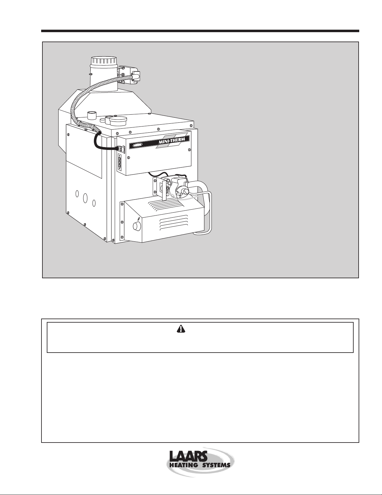
Mini-Therm II
Residential
Gas-Fired
Hydronic Boilers
Model JV
Sizes 50-225
Vent damper is optional in some provinces of Canada.
These instructions are to be stored in the packet provided on the boiler.
FOR YOUR SAFETY: This product must be installed and serviced by a professional service technician,
qualified in hot water boiler installation and maintenance. Improper installation and/or operation could
create carbon monoxide gas in flue gases which could cause serious injury, property damage, or death.
Improper installation and/or operation will void the warranty.
WARNING
If the information in this manual is not followed exactly , a fire or explosion may result
causing property damage, personal injury or loss of life.
Do not store or use gasoline or other flammable vapors and liquids in the vicinity of this or
any other appliance.
WHAT TO DO IF YOU SMELL GAS
• Do not try to light any appliance.
• Do not touch any electrical switch; do not use any phone in your building.
• Immediately call your gas supplier from a nearby phone. Follow the gas supplier's
instructions.
• If you cannot reach your gas supplier, call the fire department.
Installation and service must be performed by a qualified installer, service agency, or gas
supplier.
H0071400W
Page 2

Page 2
LAARS HEATING SYSTEMS
TABLE OF CONTENTS
SECTION 1.
General Information
1A. Introduction...................................................3
1B. Warranty....................................................... 3
1C. Field Assembly.............................................3
1D. Flow Requirements ......................................4
1E. Boiler Placement ..........................................4
1F. Gas Supply and Piping .................................5
1G. Combustion Air Supply.................................6
1H. Venting ......................................................... 7
1H-1. Common Venting System............................. 8
1I. Water Piping of Boiler System...................... 8
1I-1. By-pass Piping ............................................. 8
1J. Chilled Water Systems ...............................10
1K. Electrical Wiring.......................................... 10
1L. Filling the System ....................................... 12
SECTION 2.
Installation Instructions
2A-1. System Start-up.......................................... 14
2A-2. High Altitude Burner
Air Shutter Replacement ............................ 15
2A-3. Sequence of Operation ..............................16
2B. Water Temperature Setting ........................16
2C. Maintenance ............................................... 16
2D. Electrical Troubleshooting .......................... 17
SECTION 3.
Parts List .................................................... 21
Page 3
Mini-Therm II Hydronic Boiler
Page 3
SECTION 1.
General Information
WARNING
The JV hydronic boiler must be installed in
accordance with the procedures detailed in this
manual, or the Laars warranty will be voided. The
installation must conform to the requirements of the
local jurisdiction having authority, and, in the United
States, to the latest edition of the National Fuel Gas
Code, ANSI Z223.1. In Canada, the installation
must conform with the latest edition of CAN/CGAB149.1 OR .2 installation codes for gas burning
appliances, and/or local codes. Any modifications to
the boiler, its gas controls, gas orifices, wiring or
draft diverter may void the warranty. If field
conditions require modifications, consult the factory
representative before initiating such modifications.
1A. Introduction
This manual provides information necessary for
the installation, operation, and maintenance of Laars
Model JV copper tube hydronic boilers. These boilers
are available in two configurations; the JVT has a
thermocouple/continuous burning pilot, and the JVS
has an electronic intermittent ignition device (I.I.D.).
Look for the model designation on the rating plate,
which can be found on top of the boiler in the right
rear corner. If the unit is part of a Mini-Combo II
(model MC) Residential Gas-Fired Space/Water
Heater, refer also to Document 8001, Mini-Combo II
Installation and Operation Instructions.
The Laars automatic vent dampers are standard
on all U.S. models. The Laars side wall power venters
can be used on both JVS and JVT models. Special
instructions for their installation are included in the
vent damper and power venter package. Read them
carefully before installation.
All application and installation procedures
should be reviewed completely before proceeding with
the installation. Consult the Laars factory, or local
factory representative, with any problems or questions
regarding this equipment. Experience has shown that
most operating problems are caused by improper
installation.
Some accessory items are shipped in separate
packages. Verify receipt of all packages listed on the
packing slip. Inspect everything for damage
immediately upon delivery, and advise the carrier of
any shortages or damage. Any such claims should be
filed with the carrier. The carrier, not the shipper, is
responsible for shortages and damage to the shipment
whether visible or concealed.
1C. Field Assembly
1. Mini-Therm II boilers have built-in draft diverter
for natural draft operation.
2. Find the vent damper box which is located in the
boiler package (vent damper is optional in
Canada).
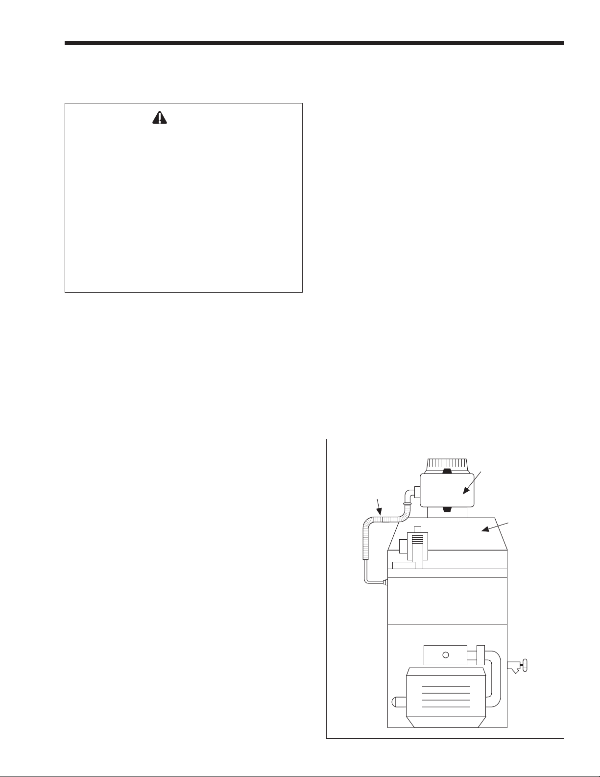
3. Install the vent damper directly to the top of the
draft diverter outlet with the damper operator
facing to the front of the boiler, and with the
flow direction arrow pointing upward. Use the
vent damper wire harness provided with the
boiler to connect the vent damper to the boiler.
The bracket end of the harness should be
connected to the vent damper actuator.
4. For Model JVS only: Install the metal plug
provided with the vent damper onto the damper
plate hole. Disregard the metal plug in case of
standing (continuous) pilot boilers. The damper
plate hole should never be blocked on all JVT
models.
Vent
Damper
Vent
Damper
Harness
(optional in
Canada)
Draft
Diverter
(built-in)
1B. Warranty
The Laars Model JV boilers are covered by a
limited warranty. The owner should fill out the
warranty registration card and return it to Laars.
All warranty claims must be made to an
authorized Laars representative or directly to the
factory. Claims must include the boiler serial number
and model (this information can be found on the
rating plate), installation date, and name of the
installer. Shipping costs are not included in the
warranty coverage.
Figure 1. Vent Damper Installation.
Page 4
Page 4
LAARS HEATING SYSTEMS
5. The field assembly is now complete. The boiler
is ready for water, gas and electrical connections
and venting installation.
6. Do not modify the automatic vent damper
device. It is very important that no other vents
are closed. Provide at least six inches clearance
between the automatic vent damper and
combustible construction, and be sure to allow
access for servicing the damper.
Caution
Do not force motor operation when operator is
fastened to the damper by moving the damper
blade, turning the shaft or by turning the position
indicator.
Note: In Canada, the vent damper is optional.
1D. Flow Requirements
All high recovery, low volume water boilers
must have adequate flow for efficient operation. Pump
selection is critical to this goal, and pumps should be
selected to provide for system design water
temperature rise. Table 1 details temperature rise and
water flow (GPM) for the Mini-Therm boilers.
Damage from improper flow is not warranted.
Failure to insure proper water flow through the
heat exchanger of the boiler will void the Laars
warranty. Flow can be verified by measuring the
difference in water temperatures between the boiler
inlet and outlet. For example: For a JV-100
installation, the inlet water temperature is 160°F
(71°C), and the outlet temperature is 180°F (82°C).
That means there is a 20° (-7°C) temperature rise
through the boiler. According to Table 1, that would
indicate a flow rate of 8 GPM (0.5L/S). Temperature
rise must be measured with the longest (highest head)
zone calling for heat alone.
Other factors to be considered before selecting a
pump are pipe size, the number of fittings throughout
the system, smoothness of the interior surface of the
pipe, the quantity of water flowing through the pipe,
whether a glycol solution is being used, and the total
length of piping in the system. Table 2 can help in
making that determination.
1E. Boiler Placement
The boiler must be placed to provide clearances
on all sides for maintenance and inspection. There
must also be minimum distances maintained from
combustible surfaces.
At least 15" (381mm) access must be available in
front of the boiler for burner removal. Consult local
codes for clearances to hot water pipes and
accessories.
If the boiler is to be installed in a garage, all
burners and burner ignition devices must have a
minimum 18" (457mm) clearance above the floor.
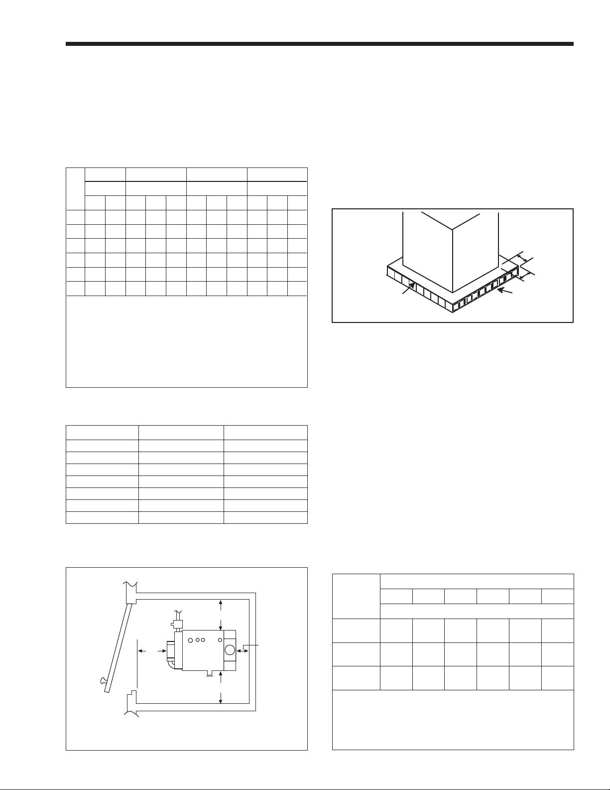
The Model JV-50 through JV-100 boilers can be
installed in a closet, as long as the minimum
clearances shown in Table 3 are observed. Special
attention should be paid to clearances between the
front of the boiler and the closet door when it is
closed.
Consult the American National Standard Z21.13
for more information concerning closet installations.
In Canada, refer to the latest edition of CAN/CGAB149.1 and 2.
IMPORTANT: The boiler shall be installed on
a floor of non-combustible construction with noncombustible flooring and surface finish and with no
combustible materials against the underside, or on
fire-resistant slabs or arches having no combustible
materials against the underside unless listed for
installation on a combustible floor.
All boilers must be installed on a noncombustible surface. That means a surface not capable
of being ignited and burning, such as surfaces
8°C
15°F
Size
50 5.3
75 8.0
100 10.7
125 13.3
160 17.0
225 24.0
ft = Pressure drop (headloss) through the boilerin feet of water.
Flow Rate Headloss Flow Rate Headloss Flow Rate Headloss
gpm
l/s
0.3
0.5
0.7
0.8
1.1
1.5
ft
0.3
0.6
1.3
2.2
2.5
5.0
gpm = Water Flow in gallons per minute.
Note: Shaded area is the recommended flow and temperature rise.
m
0.1
0.2
0.4
0.7
0.8
1.5
gpm
4.0
6.0
8.0
10.0
12.8
18.0
Table 1. Temperature Rise °F °C.
11°C
20°F
l/s
0.3
0.4
0.5
0.6
0.8
1.1
m = Pressure drop (headloss) through the boiler in meters of water.
ft
0.2
0.3
0.7
1.3
1.8
3.1
l/s = Water flow in liters per second.
m
0.1
0.1
0.2
0.4
0.5
0.9
gpm
3.2
4.8
6.4
8.0
10.2
14.4
l/s
0.2
0.3
0.4
0.5
0.6
0.9
25°F
14°C
0.1
0.2
0.5
0.8
1.2
1.9
ft
m
0.0
0.1
0.2
0.2
0.4
0.6
Page 5
Mini-Therm II Hydronic Boiler
Page 5
consisting entirely of a combination of steel, iron,
brick, tile, concrete, slate, glass or plaster.
All boilers can be installed on a combustible
floor if a non-combustible base assembly, available
from Laars, is used. See the boiler rating plate for the
appropriate base part number. Boilers must never be
installed on carpeting.
1/2" Pipe 3/4" Pipe 1" Pipe 1-1/4" Pipe
Size
Pump H.P. Pump H.P. Pump H.P. Pump H.P.
1/25 1/12 1/25 1/12 1/6 1/25 1/12 1/6 1/25 1/12 1/6
50 50 99 390 680 * * * * * * *
75 * 35 160 300 460 640 * * * * *
100 * * 77 150 260 330 620 * * * *
125 * * 27 80 140 170 360 600 * * *
160 * * * 25 72 57 160 330 190 480 *
225 * * * * * * * 110 * 69 330
*A circular and/or primary/secondary piping are required. Consult
factory.
1. Chart is based on 30°F (-1°C) maximum temperature rise.
2. Calculations are based on Type L copper tubing with one
zone valve and eight elbows.
3. Typical circulating pumps: 1/25 HP=Taco 007, B&G LR-20 or
SLC-25, Grundfos UP15-42F, or equivalent. 1/
12, Grundfos UP26-42F, or equivalent. 1/
HV, Grundfos UP43-75, or equivalent.
Table 2. Maximum Suggested Circuit Length in Feet.
Boiler Sizes 50-125 160-225
Clearances in
Left side 6
Right side 6
Rear 6
Front 4
Flue 6
Top 23
mm
152
152
152
102
152
484
Table 3. Minimum Boiler Clearances
From Combustible Surfaces.
HP=B&G LR-
12
HP=B&G series
6
in
6
6
6
6
6
36
mm
152
152
152
152
152
914
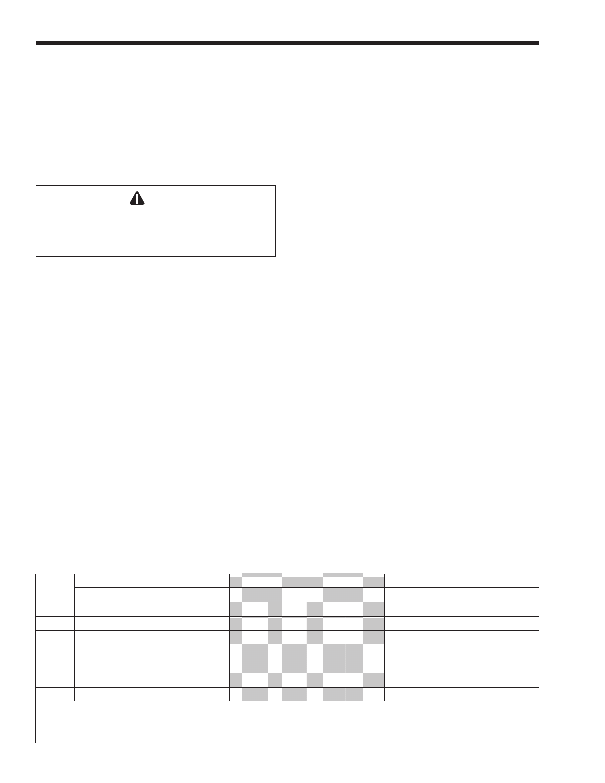
As an alternative to the Laars non-combustible
base plate, the National Fuel Code allows a boiler to
be placed on other than a non-combustible surface
when such an installation complies with the American
Insurance Code. This code specifies the surface under
the boiler be protected with hollow masonry no less
than 4" (102mm) thick, covered with sheet metal at
least 24 ga. in thickness. Such masonry must be laid
with ends unsealed, and joints matched in such a way
as to provide a free circulation of air from side to side
through the masonry (see Figure 3).
12" Min.
(305mm)
12"
Min.
Hollow
Sheet Metal Cover
Sheet Metal Cover
Min. Thickness 24 Gauge
Min. Thickness 24
Galvanized
Gauge Galvanized
Hollow
Concrete
Concrete
Block
Block
Figure 3. Typical Combustible Floor Installation.
1F. Gas Supply and Piping
Review the following instructions before
proceeding with the installation.
1. Verify that the boiler is fitted for the proper
type of gas by checking the rating plate. Laars
boilers are normally equipped
to operate below a 2000 foot altitude. Boilers
equipped to operate at higher altitudes have
appropriate stickers or tags attached (next to the
rating plate).
2. Use the figures in Table 4 to provide adequate
gas piping from the gas meter to the boiler.
3. A trap (drip leg) must be provided ahead of the
gas controls (see Figure 4). A manual gas shutoff
valve must also be provided for service
convenience and safety. Check the local codes.
6 (152)
4*
(102)
6 (152)
Dimensions in inches (mm).
*6" for models JV160 to JV225.
6 (152)
Figure 2. Closet and Alcove Installation (see Table 3).
Distance
From Gas
Meter
0-50'
0-15m
50-100'
15-30m
100-200'
30-60m
Note: These figures are for Natural Gas (.65 Sp. Gr.), and are
based on 1/2" water column pressure drop. Check supply
pressure with a manometer, and local code requirements for
variations. For LPG, reduce pipe diameter one size, but
maintain a 1/2" minimum diameter. A 'normal' number of Tees
and elbows have been taken into allowance.
50 75 100 125 160 225
1/2 3/4 3/4 3/4 1 1
3/4 3/4 3/4 1 1 1-1/4
3/4 1 1 1 1-1/4 1-1/4
Boiler Size
Pipe Size
Table 4. Gas Piping Sizes.
Page 6
Page 6
LAARS HEATING SYSTEMS
4. Disconnect the boiler from the gas supply pipe
before pressure testing the pipe for gas leaks.
Provide gas supply pressure to the boiler as
follows:
Inches Water Column Natural Gas Propane (LP)
Minimum 5.5 10
Maximum 9 14
NOTE: The boiler and all other gas appliances
sharing the boiler gas supply line must be firing at
maximum capacity to properly measure the inlet
supply pressure. Low gas pressure could be an
indication of an undersize gas meter and/or obstructed
gas supply line.
5. The correct burner manifold gas pressure is
stamped on the rating plate. The regulator is preset at the factory, and normally requires no
further adjustment.
6. Before operating the boiler, the complete gas
supply system and all connections must be tested
for leaks using a soap solution.
1G. Combustion Air Supply
The boiler location must provide sufficient
air supply for proper combustion, and ventilation
of the surrounding area as outlined in the latest
edition of ANSI standard Z223.1 or in Canada,
CAN/CGA-B149.1 or .2, and any local codes that
may be applicable.
In general, these requirements specify that boiler
rooms which represent confined spaces should be
provided with two permanent air supply openings; one
within 12 inches (305mm) of the ceiling, the other
within 12 inches (305mm) of the floor.
Outside Air Area*
Boiler Size
50 15
75 20
100 25
125 32
160 40
225 60
*Area indicated is for one of two openings; one at floor level and
one at the ceiling, so the total net free area would be double the
figures indicated. For special conditions, refer to NFPA54 ANSI
Z223.1. In Canada refer to the National Standard CAN1-
B149.1 or .2 which differs from this table.
NOTE: Check with louver manufacturers for Net Free Area of
louvers. Correct for screen resistance to the Net Free Area if a
screen is installed. Check all local codes applicable to
combustion air.
Outside Air
Sq. In.
Area in Sq. In.*
sq cm
97
129
161
206
258
387
Table 5. Minimum Recommended
Air Supply to Boiler Room.
Important
See gas line selection chart, Table 4 previous page,
for gas line sizing. In all cases, pipe size is larger
than inlet connection on heater. Run pipe size
shown in chart and reduce at heater inlet.
Inside Air Area*
Inside Air
Sq. In.
Area in Sq. In.* (sq cm)
100 645
100 645
100 645
125 807
160 1032
225 1452
sq cm
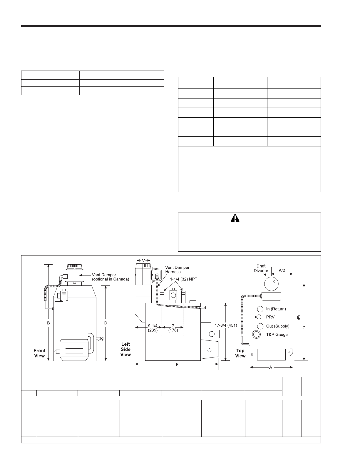
Dimensions in inches (mm)
Dimensions
inches (mm)
Size A B C D E V
50 13-3/8
75 13-3/8
100 16-7/8
125 16-7/8
160 20-3/8
225 25-5/8
340
340
429
429
518
651
27-3/4
27-
3/4 705
28-3/4
28-3/4
28-3/4
31-1/2
705
730
730
730
800
23-5/8
24-1/8
24-1/8
23-5/8
23-5/8
23-1/4
600
613
613
600
600
591
21-3/4
21-3/4
22-3/4
22-3/4
22-3/4
23-3/4
552
552
578
578
578
629
26-1/2
27-1/2
27-1/2
27-1/2
27-1/2
27-1/2
673
699
699
699
699
699
Figure 4. Dimensional Information.
Water Gas
Conn. Conn.
in. in.
4
102
5
127
5
127
6
152
6
152
7
178
1-1/4 1/ 2
1-1/4 1/ 2
1-1/4 1/ 2
1-1/4 1/ 2
1-1/4 1/ 2
1-1/4 *3/4*
*1/2 for propane
Page 7
Mini-Therm II Hydronic Boiler
Page 7
Outside Air Supply: When combustion air is
supplied directly through an outside wall, each opening
should have a minimum free area of one square inch per
4,000 BTU/h (1.2kW) input of the total input rating of
all appliances in the enclosed area.
Inside Air Supply: When combustion is
supplied from inside the building, each opening
should have a minimum free area of one square inch
per 1,000 BTU/h (0.3kW) input of the total input
rating of all appliances in the enclosed area. These
openings should never be less than 100 square inches
(645 sq. cm).
Note: In Canada, follow Canadian Standard,
CAN/CGA-B149.1, .2 or local codes.
Exhaust Fans or Vents: Any equipment which
exhausts air from the boiler room can deplete the
combustion air supply or reverse the natural draft
action of the venting system. This could cause flue
products to accumulate in the boiler room. Additional
air must be supplied to compensate for such exhaust.
The information in Table 5 is not applicable in
installations where exhaust fans or blowers of any
type are used. Such installations must be designed by
qualified engineers.
If a blower or fan is used to supply air to the
boiler room, the installer should make sure it does not
create drafts which could cause nuisance shutdowns of
the pilot. If a blower is necessary to provide adequate
combustion air to the boiler, a suitable switch or
equivalent must be wired into the boiler control circuit
to prevent the boiler from firing unless the blower is
operating.
The boiler must be completely isolated and
protected from any source of corrosive chemical
fumes such as those emitted by trichlorethylene,
perchlorethylene, chlorine, etc.
1H. Venting
The draft diverter outlet is to be connected to an
unobstructed vent pipe of the same or larger diameter,
terminating outside the building. The vent pipe must
have a listed vent cap, and extend at least two feet
above any object within a ten foot radius. All
connections should be made with rustproof sheet
metal screws.
IMPORTANT NOTE: Do not use sheet metal
screws at the snap lock joints of Type B gas vents.
Do not weld or fasten the vent pipe to the boiler
draft diverter. The weight of the stack must not rest on
the boiler.
easily removable for normal boiler service and
inspection.
elbows, reductions and restrictions. Horizontal runs
should have at least a 1/4" rise per foot (20mm per
meter) in the direction of flow. A vent connector shall
be supported for the design and weight of the material
employed to maintain clearances and prevent physical
damage and separation of joints.
conditioning or air supply fans. The fans can pick up
exhaust flue products from the boiler and return them
inside the building, creating a possible health hazard.
when used as a chimney (Type B or equivalent). In
cold weather, uninsulated outside vents can chill the
rising flue products, blocking the natural draft action
of the venting system. This can create a health hazard
by spilling flue products into the boiler room. Use
engineered venting tables acceptable to the authority
having jurisdiction to size the venting pipe or liner.
runs of the pipe which may cause excessive cooling
and condensation.
The draft diverter and boiler top must be
Avoid horizontal runs of the vent pipe, and 90°
Avoid terminating boiler vents near air
Always use double-wall or insulated vent pipe
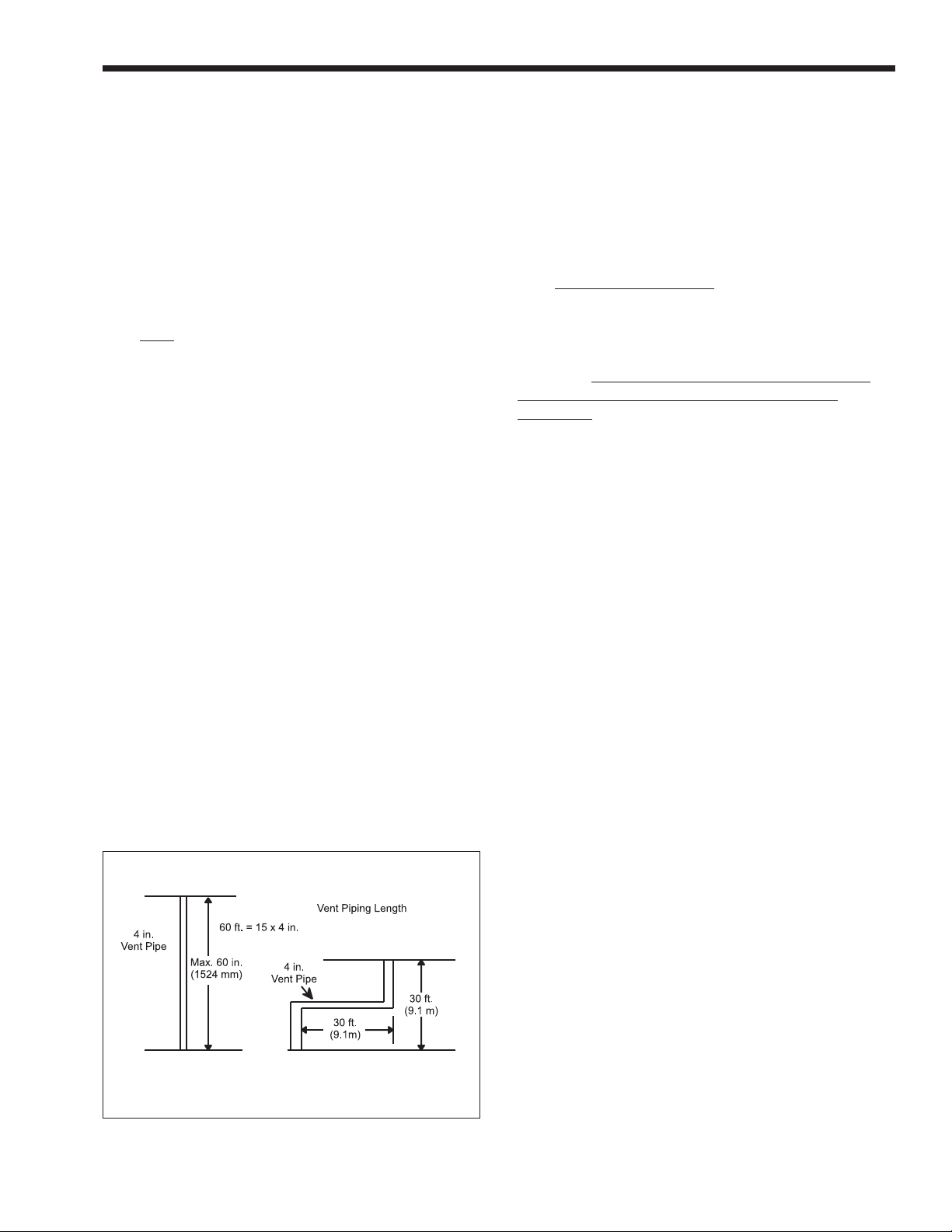
Avoid oversize vent piping or extremely long
Figure 5. Vent Pipe Sizing.
Rule of Thumb: The total length of the vent,
including the connector and any offset, should not
exceed 15 feet (4.6m) for every inch (25mm) of vent
diameter (see Figure 5). Longer total lengths shown in
venting tables are based on maximum capacity, not
condensation factors.
Before connecting a vent connector to a
chimney, the chimney passageway shall be examined
to ascertain that it is clear and free of obstructions.
When inspection reveals that an existing chimney is
not safe for the intended application, it shall be rebuilt
to conform to nationally recognized standards (see
National Building Code or ANSI/NFPA 211), lined or
relined with a suitable liner, or replaced with a vent or
chimney suitable for the equipment to be attached.
Page 8

Page 8
LAARS HEATING SYSTEMS
1H-1. Common Venting System
When an existing boiler is removed from a
common venting system, the common venting system
is likely to be too large for proper venting of the
appliances remaining connected to it.
At the time of removal of an existing boiler, the
following steps shall be followed with each appliance
remaining connected to the common venting system
placed in operation, while the other appliances
remaining connected to the common venting system
are not in operation.
1. Seal any unused openings in the common
venting system.
2. Visually inspect the venting system for proper
size and horizontal pitch and determine there is
no blockage or restriction, leakage, corrosion and
other deficiencies which could cause an unsafe
condition.
3. Insofar as it is practical, close all building doors
and windows and all doors between the space in
which the appliances remaining connected to the
common venting system are located and other
spaces of the building. Turn on clothes dryers
and any appliance not connected to the common
venting system. Turn on any exhaust fans, such
as range hoods and bathroom exhausts, so they
will operate at maximum speed. Do not operate a
summer exhaust fan. Close fireplace dampers.
4. Place in operation the appliance being inspected.
Follow the lighting instructions. Adjust
thermostat so appliance will operate
continuously.
5. Test for spillage at the draft hood relief opening
after 5 minutes of main burner operation. Use the
flame of a match or candle, or smoke from a
cigarette, cigar or pipe.
6. After it has been determined that each appliance
remaining connected to the common venting
system properly vents when tested as outlined
above, return doors, windows, exhaust fans,
fireplace dampers and any other gas burning
appliance to their previous conditions of use.
7. Any improper operation of the common venting
system should be corrected so the installation
conforms with the National Fuel Gas Code,
ANSI Z223.1. When resizing any portion of the
common venting system, the common venting
system should be resized to approach the
minimum size as determined using the
appropriate tables in Appendix G in the National
Fuel Gas Code, ANSI Z223.1.
1I. Water Piping of Boiler System
Figure 5 shows ‘typical’ plumbing installations.
Be sure to provide unions and gate valves at the
boiler inlet and outlet so it can be isolated for service.
Check local codes for specific plumbing requirements
before beginning the installation.
An ASME pressure relief valve is supplied on all
JV boilers, and is pre-set at 30 PSI. The valve outlet
piping must discharge to a drain. Under no
circumstances should the relief valve piping be a
closed circuit.
A pressure reducing valve (automatic feed) must
be used to maintain system at constant proper pressure
(see Figure 6). Supply properly installed purge valves
to eliminate air from each circuit.
A drain valve is supplied with the boiler, and can
be found in the plastic bag shipped with each boiler.
This valve is to be installed on the lower right side of
the boiler, see Figure 4, and is used for draining the
unit. To drain the boiler completely, open the drain
valve and remove the two drain plugs located on
the lower left side of the boiler.
Be sure to include air vent devices located at the
highest point in the system to eliminate trapped air,
and an air elimination device near the outlet side of
the JV boiler. Manual vent valves are recommended.
Hot water piping should be supported by suitable
hangers or floor stands, NOT by the boiler. Due to
expansion and contraction of copper pipe,
consideration should be given to the type of hangers
used. Rigid hangers could transmit noise through the
system caused by the piping sliding in the hangers. It
is recommended that padding be used when rigid
hangers are installed.
Gas piping should also be supported by suitable
hangers or floor stands, not the boiler.
A properly sized expansion tank must be
included in the system. Laars offers an aircharged
diaphragm-type expansion tank, with an automatic
feed valve, which includes a pressure regulator set at
12 psig. The part numbers are:
Less Than 20 Gallons in System A0066800
20 to 45 Gallons in System A0066900
1I-1. By-pass Piping
The following information and suggestions are
made on by-pass piping as it affects the temperature
rise at the boiler. A boiler temperature rise must be
taken on all JV boiler installations. If the temperature
rise exceeds 30°F (-1°C), it is an indication that the
boiler is not receiving adequate water flow. Check the
pump for any obstruction, replace the pump with a
larger size where necessary, or install a system bypass as indicated in Figures 6 and 7.
On JV sizes 125, 160 and 225 with a multiple
zone system, a by-pass is required to ensure proper
flow in addition to properly sized circulator and piping
system.
Page 9

Mini-Therm II Hydronic Boiler
Air Cushion Type
Expansion Tank
Purge
System
Bypass Valve
(Ball Valve)
Optional
Feed Water
Inlet
Bypass Valve
(Ball Valve)
Page 9
Optional
Pump
Location
Flo Checks
(installed at
proper places)
Multi-Zone
Pump
System
JV
Boiler
JV
Boiler
Bypass
Valves
Zone Pump
Air Scoop
Feed
Water
Inlet
Single Circuit System
Zone Pumps
(must be sized properly)
Flo Checks
Feed
Water
Air Scoop
Inlet
Multi-Zone
Valve System
Flo Checks
(installed at
proper places)
Boiler
Pump
Primary
Secondary
Multi-Zone
Pump System
JV
Boiler
JV
Boiler
12"
12"
(305mm)
max
max
Air Scoop
Zone Pump
Air Scoop
Zone Pumps
(must be sized properly)
Flo Checks
Feed
Water
Inlet
Feed
Water
Inlet
Primary/Secondary Multi-Zone Valve System
Low Temperature Installation
KEY:
PUMP CHECK VALVE VALVE ZONE VALVE UNION
Figure 6. Typical Plumbing Installations.
Zone Pump
12"
12"
(305mm)
max
JV
Boiler
max
Feed
Water
Inlet
Air Scoop
Boiler
Pump
Primary/Secondary Multi-Zone Valve System
AUTO AIR BLEEDER
Page 10

Page 10
LAARS HEATING SYSTEMS
Note: On JV sizes 160 and 225 a primary/
secondary piping system is recommended. In this
system, a circulator is dedicated to pumping the boiler
only. This circulator should be sized for the boiler
head loss and flow rate.
The two above piping configurations can also
apply to JV sizes 50, 75 and 100, especially in multizone installations, but flow rates may be obtained
without a by-pass.
All precautions must be taken by the installer to
insure that a maximum temperature rise through the
boiler does not exceed 30°F (-1°C). The temperature
rise on boilers installed in multi-zone systems using
zone valves must be taken when the zone of the
longest length and/or the zone of the highest head loss
is open.
Please note that a 1¼" diameter by-pass with
balancing ball valve must be installed if a return water
temperature of below 110°F (43°C) is expected under
operating conditions (see Figure 7).
1J. Chilled Water Systems
If the boiler is installed in conjunction with
refrigeration systems, it shall be installed so that the
chilled medium is piped in parallel with the heating
boiler with appropriate valves to prevent the chilled
medium from entering the heating boiler.
When boiler piping is connected to heating
coils, which are in close proximity to refrigerated air
circulation, there must be flow control valves or other
From
System
Balancing
Ball Valves
To
System
automatic methods to prevent gravity circulation of
the boiler water during the cooling cycle.
1K. Electrical Wiring
Follow these instructions to make the necessary
initial electrical connections.
1. Remove the two screws attaching the front cover
of the control box.
2. There are four wires coiled in the area on the
right side of the control box, supplied with wire
nuts: 2 black wires twisted together, a white wire
and a brown wire (see Figure 8).
3. Follow the schematics in Figure 9. Remove the
wire nut from the two black wires, and connect
the hot lead from a 115V power supply to both
wires. Secure the three wires with the wire nut.
The white, neutral wire should be joined to the
other neutral lead coming from the 115V power
supply, and the neutral lead coming from the
pump. The brown wire attaches to the hot side of
the pump.
4. Attach the leads from the wall thermostat to the
R and W terminals on the terminal strip, located
on the left side of the control box.
5. When using a Laars or field supplied power
venter, the proving switch must be connected in
series with the hi-limit. See wiring diagrams,
Document 1077. See Figure 1 for vent damper
connections.
6. Check the boiler wiring and pump for correct
voltage, frequency and phase. If the pump circuit
is other than 115V, be sure there is an
appropriate transformer or relay installed. The
pump relay is suitable for pumps of ¾ HP or
less.
7. For systems with multiple zone pumps or valves,
see Figure 10.
Transformer BLK
In
(Return)
Left Side View
A full size by-pass must be installed.
Figure 7. By-pass Piping. Figure 8. Field Wiring Connections.
Out
(Supply)
Drip
Leg
BRN WHT
Pump Relay
BLK - Hot
WHT - Neutral
WHT - Neutral
BRN - Hot
On = Call
for heat
115V Field Wiring
115V Factory Wiring
Power
Supply
115V AC
60 Hz
To Pump
115V AC
3/4 H.P.
Max
Page 11

Mini-Therm II Hydronic Boiler
Page 11
Figure 9a. Wiring Diagram, Spark Ignition System (JVS).
A means of disconnecting the electrical supply
must be provided within sight of the boiler. The pump
and boiler must be wired as shown to insure that the
pump is running whenever the boiler is firing.
WARNING
The boiler must be electrically grounded in
accordance with the requirements of the authority
having jurisdiction or, in the absence of such
requirements, with the latest edition of the National
Electrical Code, ANSI/NFPA 70, in the U.S. and
with latest edition of CSA C22.1 Canadian Electrical
Code, Part 1, in Canada. Do not rely on the gas or
water piping to ground the metal parts of the boiler.
Plastic pipe or dielectric unions may isolate the
boiler electrically. Service and maintenance
personnel who work on or around the boiler may be
standing on wet floors and could be electrocuted by
an ungrounded boiler.
Hi-Limit Switch: Factory setting is 190°F
(88°C). This setting is correct for normal operations,
and should only be changed by an authorized service
technician. Under no circumstances should the setting
exceed 220°F (104°C).
Flow Switch: If the system includes a flow
switch, it should be wired in series with the high-limit
Figure 9b. Schematic, Spark Ignition System (JVS).
Page 12

Page 12
LAARS HEATING SYSTEMS
Figure 9c. Wiring Diagram, Standing Pilot System (JVT).
switch. The boiler will not fire unless the pump is
running and the flow switch is closed.
Field installed safety devices and operating
controllers, such as a valve end switch, draft switches,
relays, timers, and outdoor temperature reset devices,
can be connected to the boiler through the wall
thermostat circuit. Do not exceed a draw of 30VA on
the transformer secondary.
Heat Anticipator: For single zone installations,
the wall thermostat heat anticipator should be set at
1.0 amperes. For multi-zone installations, have a
qualified electrical technician make the necessary
measurements to properly set the thermostats.
1L. Filling the System
It is crucial to the efficient operation of the
system that all air be removed from the circuit. For
this reason, an air scoop and vent should be located
close to the boiler outlet, and there should be a
minimum distance between cold water feed and
system purge valve.
1. When the system has been completely installed,
close all air vents and open the makeup water
valve. Allow the circuit to fill slowly.
2. If a make-up water pump is employed, adjust the
pressure to provide a minimum of 12 psi
(82.7kPa) at the highest point in the circuit. If a
Figure 9d. Schematic, Standing Pilot System (JVT).
Page 13

Mini-Therm II Hydronic Boiler
Page 13
Wiring
with Taco
Zone Valves
Wiring with
Honeywell
Zone Valves
Wiring
with Multiple
Zone Pumps
Figure 10. Multiple Zone Wiring.
For primary/secondary pumping: Connect
to "W" in lieu of "A." Boiler relay is used for
boiler pump and connection to "W" will
energize boiler pump when any zone is
calling for heat.
Page 14

Page 14
LAARS HEATING SYSTEMS
pressure regulator is also installed in the line,
adjust it to the same pressure.
3. Close all gate valves. Purge one circuit at a time
as follows:
a. Open one circuit drain valve and let water
drain out for at least 5 minutes. Be certain
there are no air bubbles visible in the water
stream before closing the drain valve.
b. Repeat this procedure for each circuit.
4. Open all gate valves after all circuits have been
purged.
5. Run the system circulating pump for a minimum
of 30 minutes with the boiler shut off.
6. Open all strainers in the system, and check for
debris.
7. Recheck all air vents as described in Step 3 above.
8. Some expansion tanks require visual inspection
of liquid level. If necessary, inspect the liquid
level in the expansion tank. With the system
full of water, and under normal operating
pressure, to ensure proper water level in the
expansion tank.
9. Start up boiler according to the procedures
described in Section 2 and operate the system,
including the pump, boiler, and radiation units,
for one hour.
10. Recheck the water level in the expansion tank,
if necessary. If it exceeds ½ of the volume of
the tank, open the tank drain and reduce the
water level.
11. Shut down the entire system, and vent all
radiation units and high points in the system.
12. Close the water makeup valve and check the strainer
in the pressure reducing valve for sediment or
debris. Reopen the water makeup valve.
13. Verify system pressure with the boiler pressure
gauge before beginning regular operation.
Sizes
50-225
50-225
Firing
System
Spark
Ignition
Standing
Pilot
Table 6. Gas Valve Selection.
Type of
Gas
JVS
Natural or
Propane
JVT
Natural or
Propane
Valve
Number
VR8304H Honeywell
VR8300H Honeywell
Manufacturer
SECTION 2
Operation and Maintenance
2A-1. System Start-Up
WARNING
Do not use this appliance if any part has been
under water. Immediately call a qualified service
technician to inspect the appliance and to replace
any part of the control system and any gas control
which has been under water.
1. Verify that the pump system is operating
properly:
a. Shut off the manual gas valve located
outside the boiler.
b. Raise the wall thermostat high enough to
call for heat.
c. The pump should come on immediately. If
it doesn't, test the electrical circuits.
2. Pilot Lighting:
WARNING
If you do not follow these instructions exactly, a
fire or explosion may result causing property
damage, personal injury or loss of life.
a. The JVS boilers do not require manual
lighting. The pilot is controlled by the
automatic ignition system.
b. The JVT boilers do require manual pilot
lighting. For access to the pilot burner,
remove the louvered airbox cover by
loosening the two thumb screws.
c. Different models of the JV boiler utilize
various gas valves. Although the gas valves
may have different control knobs, they are
all similar in operation. The JVS gas valve
has a two-position knob, ON and OFF. The
JVT valve has a three-position knob, ON,
OFF and PILOT, some models come with
extra push-button (see Figure 11).
14. Within 3 days of start-up, recheck and bleed all
air vents and the expansion tank using these
instructions.
VR8304 VR8300
Figure 11. Gas Valves.
Page 15

Mini-Therm II Hydronic Boiler
Page 15
3. BEFORE LIGHTING smell all around the
appliance area for gas. Be sure to smell next to
the floor because some gas is heavier than air
and will settle on the floor.
WHAT TO DO IF YOU SMELL GAS
• Do not try to light any appliance.
• Do not touch any electric switch; do not use any
phone in your building.
• Immediately call your gas supplier from a
neighbor's phone. Follow the gas supplier's
instructions.
• If you cannot reach your gas supplier, call the
fire department.
All Models:
1. Shut off electrical power to the boiler.
2. Turn the gas valve knob clockwise to OFF.
Use only your hand to push in or turn the gas
control knob. Never use tools. If the knob will
not push in or turn by hand, don't try to repair it,
call a qualified service technician. Force or
attempted repair may result in a fire or explosion.
3. Wait five (5) minutes to clear out any gas. Then
smell for gas, including near the floor. If you
smell gas, STOP! Follow 2A-1.3 in “What to do
if you smell gas”. If you don't smell gas, go to
the next step.
JVS Models:
4. Turn gas valve knob counterclockwise to ON.
5. Restore power to the boiler, and set the thermostat
to the desired temperature. The pilot will
automatically ignite when there is a call for heat.
JVT Models: (Continuous Pilot)
4. Remove louvered burner cover by loosening the
two thumb screws to access the pilot burner.
5. Remove the control box cover to fully access the
gas valve.
6. Find pilot - follow metal tube from gas control.
The pilot is on the right hand side of the first
burner.
7. Turn knob on gas control counterclockwise
to PILOT.
8. Push in control knob or push-button all the way
and hold in. Immediately light the pilot with a
match using the match holder. Continue to hold
the control knob in for about one (1) minute after
the pilot is lit. Release knob and it will pop back
up. Pilot should remain lit. If it goes out, repeat
steps 2 through 8.
a. If the knob does not pop up when released,
stop and immediately call your service
technician or gas supplier.
b. If the pilot will not stay lit after several
tries, turn the gas control knob to OFF and
call your service technician or gas supplier.
9. Replace the louvered airbox cover and tighten
the two thumb screws securely.
10. Turn gas control knob counterclockwise
to ON.
11. Replace control box cover.
12. Restore power to the boiler and adjust the
thermostat high enough to call for heat to verify
the boiler is operating properly.
13. Set the thermostat to the desired temperature.
2A-2. High Altitude Burner
Air Shutter Replacement
DANGER
This procedure must be followed exactly and
must be performed by a qualified installer or
warranty may be voided.
DANGER
Read and understand this entire procedure
prior to proceeding. Improper adjustment of
high altitude shutters may result in a fire,
explosion, and/or high levels of toxic gases
which may cause property damage, personal
injury, or loss of life.
1. STOP! Read the safety information above.
2. Perform System Start-Up in accordance with
Section 2A of this manual.
3. Remove burner cover by loosening two (2)
thumbscrews.
4. Observe flame pattern on all burners. If the flame
on any burner is pulsing, unstable or lifting
continue with this procedure. Otherwise skip to
step 10.
5. On all burners exhibiting an abnormal flame,
loosen but do not remove the air shutter locking
screw using a 5/16 inch wrench (see Figure 12).
LOCKING SCREW
(5/16" HEAD)
AIR SHUTTER
BURNER
Figure 12. Air Shutter Adjustment.
Page 16

Page 16
LAARS HEATING SYSTEMS
6. On each affected burner, slowly close the air
shutter until a normal flame is observed then retighten its associated locking screw.
7. Turn the boiler off.
8. Perform System Start-Up in accordance with
Section 2A of this manual.
9. Observe flame pattern on all burners. If the flame
on any burner is pulsing, unstable or lifting then
repeat steps 5 and 6 until all burners are
exhibiting a normal flame.
10. Re-install the burner cover and tighten it in
place.
2A-3. Sequence of Operation
1. Wall thermostat calls for heat.
2. The damper activator rotates damper blade to
open position. Indicator light comes on.
3. Pump relay will turn on the circulating pump.
4. If water temperature is below the limit setting on
the spark ignition models will light the pilot and
check the flame existence.
5. After pilot is proven to be lit, the main gas valve
will open, the main burners will ignite and
continue until either the hi-limit or wall
thermostat opens.
6. When the wall thermostat is satisfied, the burners
will shut off. The pump relay will turn off the
pump, and the damper will close. When the room
temperature falls below the wall thermostat
setting, the cycle will repeat.
Note: When equipped with pump delay option,
the pump will run for short time after the burners turn
off and the damper closes.
2B. Water Temperature Setting
In Canada, for models equipped with modulating
gas valves, in addition to the main gas valve. These
controls are factory set at "5" which is satisfactory for
most installations. Lower settings may be appropriate
for radiant floor systems, or when heating
requirements are low. To change the factory setting
simply adjust the red knob on the valve to the desired
water temperature according to Table 7 (temperatures
are approximate).
2C. Maintenance
1. Lubricate the water circulating pump per the
instructions on the pump.
2. If a strainer is employed in a pressure reducing
valve or the piping, clean it every six months.
3. At start-up, and periodically thereafter, the
burner flame should be observed. If the flame
has the appearance of 'sooting' tips, check for
debris near the orifices and call the service
technician.
4. Inspect the venting system for obstruction,
leakage or corrosion at least once a year.
5. Keep the boiler area clear and free from
combustible materials, gasoline, and other
flammable vapors and liquids.
6. Be sure that all combustion air and ventilation
openings are unobstructed.
7. Upon completion of the installation, inspect the
external surfaces of the heat exchanger for
fouling based on the following schedule:
24 hours 7 days 30 days 90 days
Once every six months thereafter.
8. If the boiler is not going to be used for long
periods of time in locations where freezing
occurs, it should be completely drained of all
water. To accomplish this, there is a drain valve
on the right side of the boiler which can be
opened. This will drain the right side of the
boiler. There are two plugs located on the left
side of the heater which must be removed to
drain that side. Both sides must be drained.
9. The gas and electric controls on the boiler are
engineered for long life and dependable
operation, but the safety of the equipment
depends on their proper functioning. It is
strongly recommended that the basic items listed
below be inspected by a qualified service
technician every year.
a. Water temperature controls
b. Pilot safety system.
c. Automatic gas valves.
d. Flow sensing safety devices.
e. Vent dampers and power venters.
Dial
Number
Temp. °F 120 135 150 165 180 195 210 225 240
Temp. °C 49 57 66 74 82 91 99 107 116
1 2 3 4 5 6 7 8 9
Table 7. Water Temperature Settings.
Figure 13. 1) JVS Pilot; 2) JVH Pilot;
3) Main Burner Flame Pattern; 4) JVT Pilot.
Page 17

Mini-Therm II Hydronic Boiler
Page 17
10. Low water cutoffs should be inspected and
flushed periodically.
Note: The Warranty does not cover damage
caused by lack of required maintenance, lack of
water flow, or improper operating practices.
Fouling on the external surfaces of the heat
exchanger is caused by incomplete combustion, and is
a sign of venting and/or combustion air problems. The
heat exchanger can be inspected by using a flashlight
and placing a mirror under the burners. An alternate
method is to remove the venting and top panel to
inspect the exchanger from above. The vent system
should be inspected at the same time. If cleaning is
required:
a. Shut off all power to the boiler.
b. Remove the draft hood, venting top, flue
collector, and heat exchanger baffles.
c. Remove the burners by lifting them off the
orifices and pulling them out of the boiler.
d. Use a hand-operated spray bottle filled with
water, and a wire brush to clean soot and loose
scale from the underside of the heat exchanger.
DO NOT USE COMPRESSED AIR, HIGH
PRESSURE WATER OR A GARDEN HOSE.
e. Clean any fallen debris from the bottom of the unit.
f. Check to make sure the burner ports and pilot
assembly are free of debris before returning the
burners to their original position.
g. Reassemble the boiler in reverse order, making
sure to replace the heat exchanger baffles.
2D. Electrical Troubleshooting
1. Remove the control box cover on the front of the
boiler.
2. Verify that 115V is reaching the boiler by testing
across the black wire on the pump relay and the
white wire on the transformer.
3. Verify 24V transformer output by placing the
meter leads on the yellow and red wires. If 24V
is not evident, replace the transformer. Perform
the following series of tests with one meter lead
attached to the yellow wire on the transformer.
4. Place the second lead on the "W" connection on
the terminal board. Turn the wall thermostat high
enough to call for heat. If the meter fails to
register 24V, the thermostat or its circuit may be
defective.
5. Make sure thermostat is set high enough to call
for heat. Place second lead on the "A" connection on the terminal board. If voltage is evident,
skip to step 6. If no voltage, test the circuit
between the red wire on the transformer and
terminal 4 on the pump relay; from terminal 6 on
the pump relay and the "A" connection on the
terminal board; and from the purple wire terminal on the pump relay to the "W" connection on
the terminal board. If no output is found, the
connections or the pump relay could be defective.
6. Place the second lead on the orange wire terminal on the hi-limit switch. If no voltage across
the switch, check for defective hi-limit, open
circuit due to excessive water temperature, or a
low temperature setting.
7. Place the second lead on the orange wire terminal on the blocked vent safety switch. If voltage
is present, the vent damper is open. If voltage
isn't present, connections or the vent damper
could be defective.
8. Verify the voltage across the blocked vent and
roll-out safety switches.
9. On JVT boilers, test for voltage at the "TH"
terminal on the gas valve. If none is found,
follow steps 1 through 8.
10. If it is determined that there is voltage to the gas
valve, the pilot is lit and the thermocouple is
properly positioned, and the thermostat is set
high enough to call for heat, the gas valve or the
pilot thermocouple may be defective
11. There are two tests necessary to make sure the
problem is not in the pilot thermocouple. The
first test can be performed by unscrewing the
compression fitting on the gas valve, and placing
one millivoltmeter lead on the center post of the
tube and the other lead on the copper tubing. If
the meter shows a reading of approximately 30
millivolts, proceed to the second test. If it
doesn't, replace the pilot thermocouple. The
second test requires the use of a Millivolt Reading Adapter to test the thermocouple under load.
Once again, remove the pilot thermocouple
compression fitting from the gas valve. Replace
it with a Millivolt Reading Adapter, and screw
the thermocouple fitting into the end of the
adapter. Attach one lead from the millivoltmeter
to either side of the adapter and the other lead to
ground. Light the pilot and set the wall thermostat high enough to call for heat. With the boiler
firing, take a millivolt reading. It should be in the
15 millivolt range. If it isn't, replace the pilot
thermocouple.
Caution
Label all wires prior to disconnection when servicing
controls. Wiring errors can cause improper and
dangerous operation. Verify proper operation after
servicing.
Page 18

Page 18
# Symptom Cause Remedy
LAARS HEATING SYSTEMS
1. Pump not A.No power A.Check circuit breakers and power source.
operating B . Pump defective B.Replace.
C.Incorrectly wired C.Recheck wiring diagrams.
2. Pilot outage A. Inlet gas pressure too low A. Consult gas utility company. Inlet gas pressure to boiler
should be 5.5" to 10.0" water column on natural gas. 11.0" to
B.Inlet gas pressure too high causing
an unstable blowing pilot B.Pressure should be regulated within limits shown above.
C.Weak or defective thermocouple C.Replace thermocouple.
D.Damaged pilot or thermocouple D.Replace.
E.Dirty pilot E.Blow dust or lint out of pilot.
F. Plugged or undersized pilot orifice F. Clean or replace pilot orifice.
14.0" on propane gas.
3. Flame roll-out A.Blocked flue A.Remove blockage.
on start-up B.Pilot out of position (delayed ignition) B.Correct pilot position.
C.Blocked heat exchanger or flue C.Clean and correct as necessary.
D.Refractory tile out of place D.Correct or replace tile as necessary.
E.Altered draft diverter E.Install factory-provided draft diverter.
4. Spillage at A.Cold chimney A.Allow boiler to operate 5 minutes to create draft action.
draft hood B.Vent pipe pitches down to chimney B. Reinstall vent pipe to pitch up from boiler to chimney.
C.Blocked chimney C.Remove blockage.
D.Draft hood altered D.Install factory-provided draft diverter.
E.Pre-fabricated chimney with incorrect cap E.Install U.L. listed vent cap.
5. Flame has A.Low primary air A.Correct manifold pressure according to rating plate. Correct
lazy yellow tip orifice size if necessary (see parts list). Clean burner ports if
dirty.
6. Not enough heat A.Inadequate gas supply A.Gas meter too small. Gas line from meter to boiler too small.
B.Low manifold gas pressure B. Gas pressure on boiler manifold, with Modusnap valve wide
C.Boiler size inadequate C.Replace with boiler of higher input.
open. Should be adjusted to 4.0"W.C. natural gas, 9.0"W.C.
propane.
7. Pump noisy A.Air in volute A.Bleed air from volute. Check pump alignment.
B.Worn coupling or bearings B.Replace worn parts.
8. Boiler pounding A. Too low water flow through boiler A. Check temperature rise between inlet and outlet boiler piping.
or knocking 15°F to 25°F temperature rise is recommended. If temperature
rise is over 25°F, increase pipe size or pump capacity or
locate obstruction. Check for stuck closed zone valves.
Check for zone pumps not operating. Check for closed valve
in system.
9. Boiler condensing A. Low water temperature A.Flue product moisture will condense at the start-up until the
boiler water temperature reaches the normal operating
conditions.
10. Pump cavitates A.Defective fill valves or pressure regulator A. Replace.
or low water B.Oversized expansion tank B.Replace.
pressure at boiler C.Expansion tank piped incorrectly C.Repipe expansion tank to suction size of pump.
gauge or bubbles
in system at high
temperature
11. Pressure relief A.Water-logged expansion tank A.Drain
valve opens
2
/3 of the water from the expansion tank.
12. Pilot is lit but main A.Gas valve not at "on" position A.Turn knob to "on" position.
burners will not B.Boiler off on hi-limit control B. Check for low water flow or hi-limit setting.
come on C.Boiler incorrectly wired C.On single or multiple zone systems with zone valves, room
D.Boiler off on blocked vent switch D.Remedy as in symptom #4. Reset the manual reset switch.
E.Boiler off on flame roll-out switch E.Remedy as in symptom #3. Reset the manual reset switch.
F. Broken wire in thermostat circuit
or defective thermostat F. Check continuity through thermostat circuit with wires
thermostat should be wired to R & W terminals. For multiple
zone systems with zone pumps, thermostats for extra zones
should be wired to R & A terminals.
disconnected from R & W.
13. Boiler short cycles A.Heat anticipator in room thermostat
set too low A.Increase setting (1.0 is usually satisfactory).
B.Low water flow through boiler B.Increase size of pump or increase piping size.
C.Hi-limit switch may be set too low C.Increase setting to at least 20°F over outlet water temperature.
Table 8. Troubleshooting Analysis.
Page 19

Mini-Therm II Hydronic Boiler
Troubleshooting Honeywell S8600
Some heaters may be equipped with an ignition module that shuts off pilot gas if pilot fails to light.
Start
Turn off gas supply.
Turn thermostat
(controller) to call for
heat.
Power to module
(24V nominal).
YES
Spark across igniter/
sensor gap.
Intermittent Pilot System
To reset, interrupt power to heater
Note: Before troubleshooting, familiarize yourself with the start-up and
checkout procedure.
Check line voltage power, low voltage transformer, hi- limit switch,
NO
NO
thermostat (controller) and wiring.
Pull ignition lead and check spark at module.
Spark okay?
YES
Page 19
YES
Turn gas supply on.
Pilot burner lights?
YES
Spark stops when pilot
is lit?
YES
Main burner lights?
YES
NO
NO
NO
• Check ignition cable ground wiring, ceramic insulator and gap, and correct.
• Check boot of the ignition cable for signs of melting or buckling. Take
protective action to shield cable and boot from excessive temperatures.
• Check that all manual gas valves are open, supply tubing and pressures
are good, and pilot burner orifice is not blocked.
• Check electrical connections between module and pilot operator on gas
control.
• Check for 24 Vac across PV-MV/PV terminals on module. If voltage is
okay, replace gas valve; if not, replace module.
Note: If S8600H goes into lockout, reset system. Lockout is used on
L.P.G. models.
• Check continuity of ignition cable and ground wire.
• Clean flame rod.
• Check electrical connections between flame rod and module.
• Check for cracked ceramic flame rod insulator.
• Check that pilot flame covers flame rod and is steady and blue.
• Adjust pilot flame.
• If problem persists, replace module.
• Check for 24 Vac across MV-MV/PV terminals. If no voltage, replace
module.
• Check electrical connections between module and gas valve. If okay,
replace gas valve.
System runs until call for
heat ends?
YES
Call for heat ends.
System shuts off?
YES
Troubleshooting ends
NO
NO
Note: If S8600H goes into lockout, reset system.
• Check continuity of ignition cable and ground wire.
Note: If ground is poor or erratic, shutdowns may occur occasionally even
though operation is normal at the time of checkout.
• Check that pilot flame covers flame rod and is steady and blue.
• If checks are okay, replace module.
• Check for proper thermostat (controller) operation.
• Remove MV lead at module; if valve closes, recheck temperature
controller and wiring; if not, replace gas valve.
Repeat procedure until trouble-free operation is obtained.
Page 20

Page 20
LAARS HEATING SYSTEMS
Glossary of Terms
Air Vent
Another device used to purge air from the Circuit.
Should be located at the highest point in the Circuit.
Branch
The section(s) of supply and return piping, including
the heat distribution units (see below), connected
directly to the trunk. Also referred to as a "zone."
By-pass
A section of pipe (including an adjustable valve) that
diverts part of the water flow from undersized piping
to the boiler. Adjusted to maintain minimum flow
requirement (GPM) through the boiler.
Circuit
Entire water circulation piping, beginning and ending
at the boiler (Series Loop System).
Expansion Tank (Compression Tank)
Installed in the circuit to accommodate excess water
produced by heat expansion.
Heat Distribution Units
Transfers heat from the water supplied by the boiler to
the area to be heated through the use of baseboard,
convector, radiator, finned tube. Also known as
"radiation."
Isolation Valve
Used to isolate the boiler from the circuit. It minimizes
the amount of water drained from the system.
Primary-Secondary Piping
Two or more interconnecting circulating loops, each
with its own pump. Primary=System Circuit;
Secondary=Boiler Circuit.
Reverse-return Piping
Balanced, equal flow (first in, last out) piping. Utilized
with multiple boilers and/or radiation. Applied with
single system pumps, or primary-secondary pumps.
Side Wall Power Venter
This Laars accessory allows the boiler exhaust to be
routed horizontally through an adjoining outside wall,
rather than gravity venting with a chimney or stack
when local codes allow.
System Purge Valve
A device used to purge air from the circuit. Should be
located as close as possible to the cold water feed,
but not immediately after the cold water feed.
Trunk
The section of piping which connects the boiler return
and supply with the branch(es). Also known as a
"main" or "header." Should be same size as boiler
inlet/outlet connections.
Vent Damper (optional in Canada)
Standard on JV boilers. This energy-saving device
prevents heated air from exiting the open vent when
the boiler is not operating.
Zone Pump
Circulators installed in branch piping that divert hot
water coming from the boiler into various areas
(zones) of a building.
Zone Valve
Diverts hot water from the boiler into various areas
(zones) of a building.
Page 21

Mini-Therm II Hydronic Boiler
Page 21
SECTION 3.
Parts List and Ordering Information
Part Number
Description Model, Size JVS-50 JVT-50 JVS-75 JVT-75 JVS-100 JVT-100 JVS-125 JVT-125
Pilot Gas System
Pilot Assembly (Nat.) W0030600 W0040900 W0030600 W0040900 W0030600 W0040900 W0030600 W0040900
Pilot Assembly (LP) W0039600 W0040901 W0039600 W0040901 W0039600 W0040901 W0039600 W0040901
Thermocouple - W0036500 - W0036500 - W0036500 - W0036500
Main Gas System
Burner W/Pilot Bracket L0056500 L0056500 L0056500 L0056500 L0056500 L0056500 L0056500 L0056500
Burner, Main L0052500 L0052500 L0052500 L0052500 L0052500 L0052500 L0052500 L0052500
Burner/Air Shutter (LP) L0055900 L0055900 L0055900 L0055900 L0055900 L0055900 L0055900 L0055900
Gas Valve, HW., VR8304 (Nat.) V2002200 - V2002200 - V2002200 - V2002200 Gas Valve, RS (Nat.) - R0017500 - R0017500 - R0017500 - R0017500
Gas Valve, HW., VR8300 (LP) - V2002100 - V2002100 - V2002100 - V2002100
Gas Valve, HW., VR8304 (LP) V0073600 - V0073600 - V0073600 - V0073600 Gas Orifice (Nat.) L0032200 L0032200 L0032200 L0032200 L0032200 L0032200 L0032200 L0032200
Gas Orifice (LP) L0032900 L0032900 L0032900 L0032900 L0032900 L0032900 L0032900 L0032900
Gas Manifold L0052601 L0052601 L0052602 L0052602 L0052603 L0052603 L0052604 L0052604
Electrical System
Relay, DPNO E0088400 E0088400 E0088400 E0088400 E0088400 E0088400 E0088400 E0088400
Transformer 115/24V (40VA) E0086100 E0086100 E0086100 E0086100 E0086100 E0086100 E0086100 E0086100
Ignition Control (S8600F) Nat. E0094001 - E0094001 - E0094001 - E0094001 Limit Switch E0098700 E0098700 E0098700 E0098700 E0098700 E0098700 E0098700 E0098700
Control Panel Wiring Harness 20406501 20406501 20406501 20406501 20406501 20406501 20406501 20406501
Power Venter Jumper 20036700 20036700 20036700 20036700 20036700 20036700 20036700 20036700
Terminal Strip E0098500 E0098500 E0098500 E0098500 E0098500 E0098500 E0098500 E0098500
Hi-Tension Lead 10449514 - 10449514 - 10449514 - 10449514 Blocked Vent SafetySwitch* E0121000 E0121000 E0121000 E0121000 E0121000 E0121000 E0121000 E0121000
Roll-out Safety Switch E2103200 E2103200 E2103200 E2103200 E2103200 E2103200 E2103200 E2103200
Fuse, 2 amp E2043600 E2043600 E2043600 E2043600 E2043600 E2043600 E2043600 E2043600
Water System
Heat Exchanger 20036601 20036601 20036602 20036602 20036603 20036603 20036604 20036604
Temperature/Pressure Gauge A0000100 A0000100 A0000100 A0000100 A0000100 A0000100 A0000100 A0000100
Pressure Relief Valve, 30PSI A0069000 A0069000 A0069000 A0069000 A0069000 A0069000 A0069000 A0069000
Well, Immersion E2058300 E2058300 E2058300 E2058300 E2058300 E2058300 E2058300 E2058300
Drain Valve 1/2" NPT P0066600 P0066600 P0066600 P0066600 P0066600 P0066600 P0066600 P0066600
Jacket and Fire Box Components
Draft Diverter 20034801 20034801 20034802 20034802 20034803 20034803 20034804 20034804
Rear Panel 20099801 20099801 20099802 20099802 20099803 20099803 20099804 20099804
Side Panel (L&R) 10467900 10467900 10467900 10467900 10467900 10467900 10467900 10467900
Front Panel 10484701 10484701 10484702 10484702 10484703 10484703 104884704 10484704
Top 20099401 20099401 20099402 20099402 20099403 20099403 20099404 20099404
Gap Closure 20099501 20099501 20099502 20099502 20099503 20099503 20099504 20099504
Flue Collector 20034901 20034901 20034902 20034902 20034903 20034903 20034904 20034904
Access Panel HX, (L&R) 10535900 10535900 10535901 10535901 10535900 10535900 10535901 10535901
Base, Control Box 10469200 10469200 10469200 10469200 10469200 10469200 10469200 10469200
Cover, Control Box 10469400 10469400 10469400 10469400 10469400 10469400 10469400 10469400
Burner Cover 10500601 10500601 10500601 10500601 10500602 10500602 10500602 10500602
Heat Exchanger Baffle 10485301 10485301 10485302 10485302 10485303 10485303 10485304 10485304
Tile Cover 10469501 10469501 10469502 10469502 10469503 10469503 10469503 10469504
Refractory, Front T0022001 T0022001 T0022002 T0022002 T0022003 T0021803 T0022004 T0022004
Refractory, Rear T0021701 T0021701 T0021702 T0021702 T0021703 T0021703 T0021704 T0021704
Insulation, Fiberglass T0027300 T0027300 T0027300 T0027300 T0002000 T0027300 T0027300 T0027300
Base Assembly 10467101 10467101 10467012 10467102 10467103 10467103 10467104 10467104
Combustible Base (optional) 10466701 10466701 10466701 10466701 10466702 10466702 10466702 10466702
Vent Damper Components
Automatic Vent Damper Assy., Penn Q35* E2071501 E2071501 E2071502 E2071502 E2071502 E2071502 E2071503 E2071503
Damper Connection Harness* E0099100 E0099100 E0099100 E0099100 E0099100 E0099100 E0099100 E0099100
* Optional in Canada.
Page 22

Page 22
Part Number
Description Model, Size JVS-160 JVT-160 JVS-225 JVT-225
Pilot Gas System
Pilot Assembly (Nat.) W0030600 W0040900 W0030600 W0040900
Pilot Assembly (LP) W0039600 W0040901 W0039600 W0040901
Thermocouple - W0036500 - W0036500
Main Gas System
Burner W/Pilot Bracket L0056500 L0056500 L0056500 L0056500
Burner, Main L0052500 L0052500 L0052500 L0052500
Burner/Air Shutter (LP) L0055900 L0055900 L0055900 L0055900
Gas Valve, HW., VR8304H (Nat.) V2002200 - V2002200 Gas Valve, RS (Nat.) - R0017500 - R0017500
Gas Valve, HW., VR8300H (LP) - V2002100 - V2002100
Gas Valve, HW., VR8304H (LP) V0073600 - V0073600 Modulating Valve, HWV 5155A 1/2" x 1/2" (Canada) V0051100 V0051100 V0051100 V0051100
Modulating Valve, HWV 5155A 1" x 1" (Canada) - - V0045100† V0045100†
Gas Orifice (Nat.) L0050700 L0050700 L0050700 L0050700
Gas Orifice (LP) L0032900 L0032900 L0032900 L0032900
Gas Manifold L0052606 L0052606 L0052607 L0052607
Electrical System
Relay, DPNO E0088400 E0088400 E0088400 E0088400
Transformer 115/24V (40VA) E0086100 E0086100 E0086100 E0086100
Ignition Control (HW S8600F) NAT. E0094001 - E0094001 Ignition Control (S8610M) LP. E2102800 - E2102800 Limit Switch E0098700 E0098700 E0098700 E0098700
Control Panel Wiring Harness 20406501 20406501 20406501 20406501
Power Venter Jumper 20036700 20036700 20036700 20036700
Terminal Strip E0098500 E0098500 E0098500 E0098500
Hi-Tension Lead 10449515 - 10449516 Blocked Vent Switch* E0121000 E0121000 E0121000 E0121000
Roll-out Safety Switch E2103200 E2103200 E2103200 E2103200
Fuse, 2 amp. E2043600 E2043600 E2043600 E2043600
Water System
Heat Exchanger 20036605 20036605 20036606 20036606
Temperature/Pressure Gauge A0000100 A0000100 A0000001 A0000100
Pressure Relief Valve, 30PSI A0069000 A0069000 A0069000 A0069000
Well, Immersion E2058300 E2058300 E2058300 E2058300
Drain Valve 1/2" NPT P0066600 P0066600 P0066600 P0066600
Jacket and Fire Box Components
Draft Diverter 20034805 20034805 20034806 20034806
Rear Panel 20099805 20099805 20099806 20099806
Side Panel (L&R) 10467900 10467900 10467900 10467900
Front Panel 10501605 10501605 10501606 10501606
Top 20099405 20099405 20099406 20099406
Gap Closure 20099504 20099504 20099506 20099506
Flue Collector 20034905 20034905 20034906 20034906
Access Panel HX (L&R) 10535901 10535901 10535901 10535901
Base, Control Box 10469200 10469200 10469200 10469200
Cover, Control Box 10469400 10469400 10469400 10469400
Burner Cover 10494105 10494105 10494106 10494106
Heat Exchanger Baffle 10485305 10485305 10485306 10485306
Tile Cover 10469505 10469505 10469506 10469506
Refractory, Front T0022605 T0022605 T0022606 T0022606
Refractory, Rear T0021705 T0021705 T0021706 T0021706
Insulation, Fiberglass T0027300 T0027300 T0027300 T0027300
Base Assembly 10467105 10467105 10467106 10467106
Combustible Base (Optional) 10466703 10466703 10466704 10466704
Vent Damper Components
Automatic Vent Damper Assy. (Penn Q35)* E2071503 E2071503 E2071504 E2071504
Damper Connection Harness* E0099101 E0099101 E0099101 E0099101
*Optional in Canada
LAARS HEATING SYSTEMS
TO OBTAIN OR ORDER PARTS: Check with your nearest Laars dealer or distributor. They have many of the commonly needed parts in stock. If your dealer
cannot supply you, contact the Service Department at Laars. See address and telephone information on back page of this document.
Page 23

Mini-Therm II Hydronic Boiler
Page 23
Figure 13. Parts Identification.
Figure 13 - Parts Identification
Page 24

H0071400W
Waterpik Technologies, Inc.
6000 Condor Drive, Moorpark, CA 93021 • 805.529.2000 • FAX 805.529.5934
20 Industrial Way, Rochester, NH 03867 • 603.335.6300 • F AX 603.335.3355
480 S. Service Road West, Oakville, Ontario, Canada L6K 2H4 • 905.844.8233 • FAX 905.844.2635
www.laars.com
Litho in U.S.A. © Laars Heating Systems 0011 Document 1025W
 Loading...