

Page 1
INSTALLATION OF VENTING SYSTEM COMPONENTS
LAARS EverHot®
Doc. 11046
When installing the EVERHOT® IGI model series direct vent water heaters, use only EVERHOT
vent/air intake system kits and components. Installation and service must be performed by a
qualified installer, service agency or the gas supplier. Installation must meet all state and local
codes regarding installation and location of vent systems for direct vent appliances. In the
absence of local codes, the National Fuel Gas Code, ANSI Z223.1/NFPA 54 and/or CSA B149.1,
Natural Gas and
Propane Installation Code. The maximum vent length, as stated in the EVERHOT IGI model series
Water Heater Installation and Operating Instruction Manual and these instructions, should never be
exceeded. Follow the instructions below and all instructions located in the EVERHOT IGI model
series Water Heater Installation and Operating Instruction Manual when installing a vent pipe
system. Improper installation of vent piping, or failure to follow all installation instructions
completely, can result in property damage, and/or death.
WARNING
WARNING
Refer to the LAARS EVERHOT® IGI series Water Heater Installation and Operating Instruction
Manual for details concerning vent system termination positions/clearances, allowable vent pipe lengths, and
in what position dip switch #1 should be placed. If you do not understand how to configure your vent pipe
system and/or which position dip switch #1 should be placed in, please contact your supplier for assistance.
WARNING
All joints in the vent/air intake piping must be taped with aluminu m tape at the completion of the venting system
installation to prevent any possible leakage into the room.
Make sure all the pipe connections are firmly pressed together so that the gaskets form a tight seal.
Prior to the Installation of EVERHOT® direct vent systems:
The EVERHOT® IGI water heaters have two adjustable wall mounting support brackets fitted on
the top and bottom of the appliance. When installing a “Standard Vent Discharge Kit" to vent
directly through the wall to the back of the water heater, these brackets should be adjusted so
that the water heater is spaced its maximum distance of 2" (5.1 cm) away from the wall. Before
cutting the vent terminal to the appropriate length, ensure you have taken into account just how
far the heater has been spaced away from the wall.
NOTICE
When mounting the water heater on an outside wall, be sure the Vent/Air Intake Pipe will exit between the
wall studs. DO NOT cut through the wall studs for the Vent/Air Intake Pipe opening.
Page 2
WARNING
All joints in the vent/air intake piping must be taped with aluminum tape at the completion of the venting
system installation to prevent any possible leakage into the room.
Make sure all the pipe connections are firmly pressed together so that the gaskets form a tight seal.
WARNING
Before installation inspect each vent component for damage and correct seal placement. Do not attempt to
fix or install any damaged vent components.
Condensate
When the total vent system length is greater than 5 ft. (1,52 m), condensate will form which could
damage the water heater. For vent lengths greater than 5 ft. (1,52 m), a condensate collector and
trap must be installed.
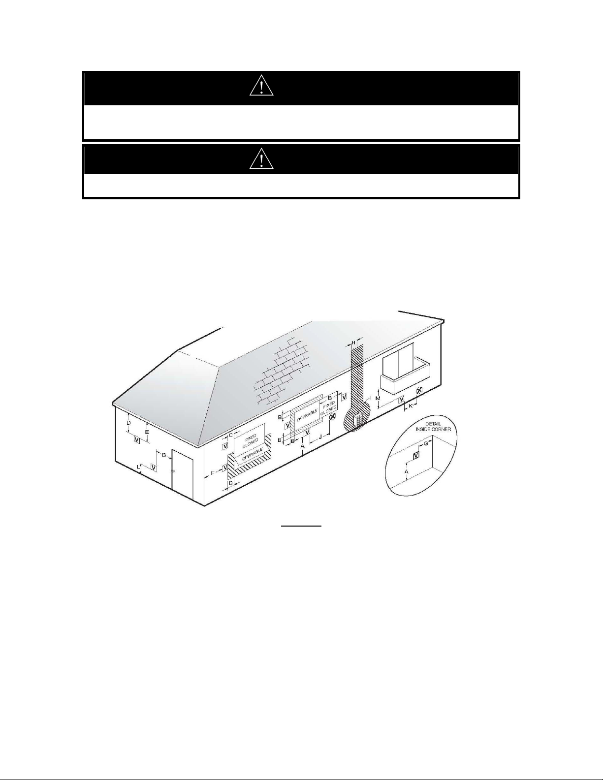
Recommended vent/air intake terminal position
Terminals should be so positioned as to avoid products of combustion entering openings into buildings or
other flues or vents.
Figure 12
2
Page 3
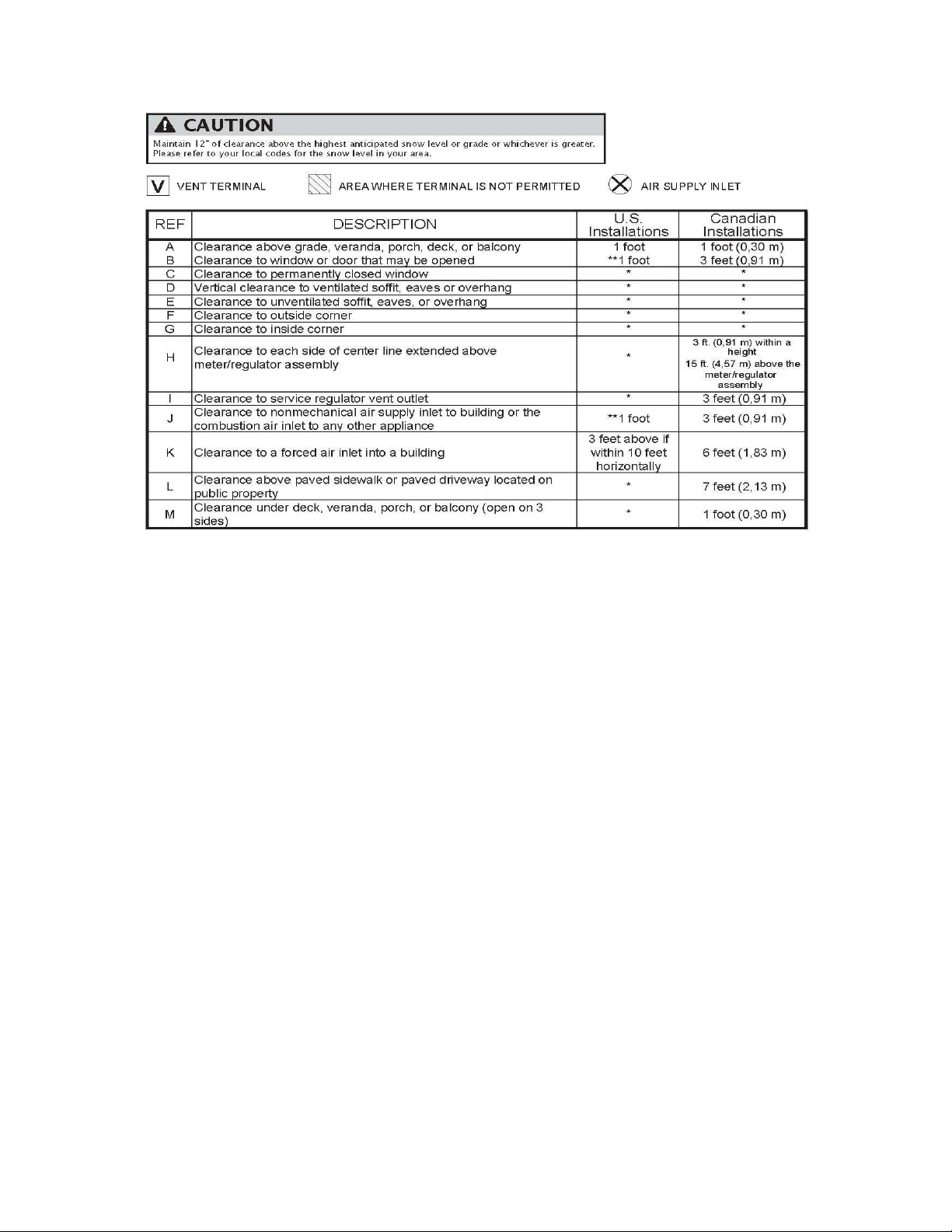
* For clearances not specified in ANSI Z223.1 / NFP A 54 or CGA-B149, please use clearances in accordance with
local installation codes and the requirements of the gas supplier .
** For other than Direct Vent Appliance, 4 feet (1.22 m) below or to side of opening; 1 foot (300 mm) above opening.
3
Page 4
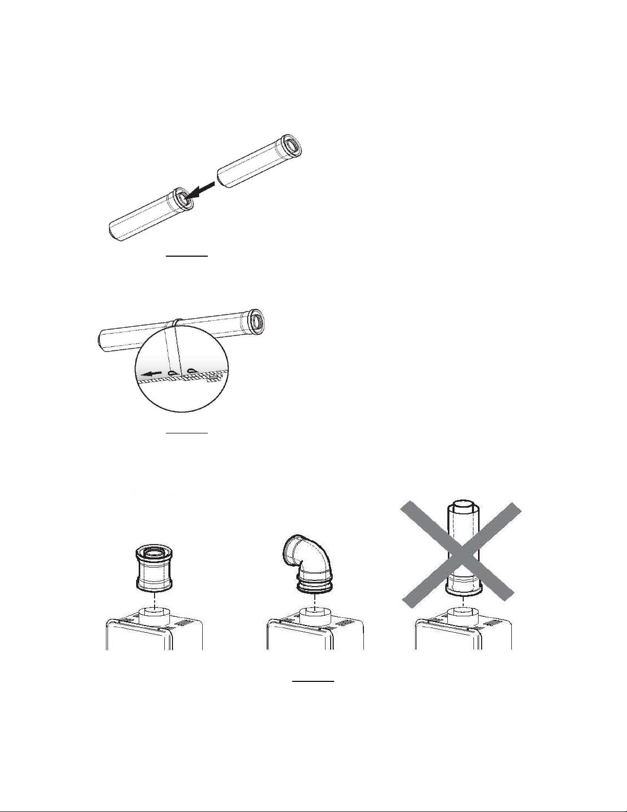
Joint connection
General Installation Instructions
Vent connections others must be firmly pressed together so that the gaskets form an airtight seal.
Figure 13
Coping with condensation
Make sure that the sockets are pointed 1° upwards in order to keep the gaskets dry. (Except for the (short
distance) standard horizontal discharge vent system without extensions. See Figure 34.)
Figure 14
Appliance connection
Figure 15
The first vent component to the appliance must be a vertical discharge adapter or a horizontal discharge
adapter. Never use an extension as the first component, this might cause damage to the water heater and
vent system. Secure vent connections with pipe clamps or perforated hanger.
4
Page 5
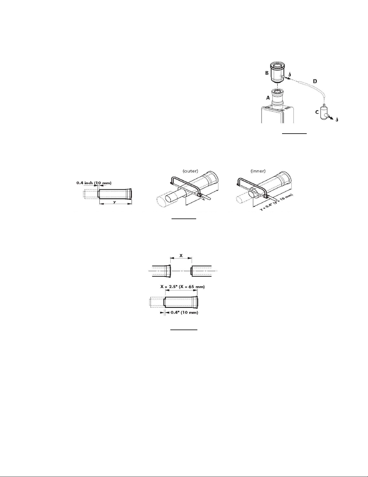
Condensate drain
Every vent system should have a condensate collector unless
installed with a total vent length of less than 5 ft. (1,52 m).
To prevent condensate from draining back to the applian ce, a
condensate collector (B) and trap (C) should be installed. Attach
condensate collector to the discharge adapter (A). The trap must be
inspected annually for obstructions and water content in the trap.
Provisions must be made to properly drain and dispose of
condensate; be aware that condensate is a highly corrosive substance
that could damage metals. The hose (D) should be subject to
inspection; kinks must be avoided. Dispose of condensate in
accordance with local codes. Minimum water level in the condensate
trap must be 3” (75 mm).
Shortening of vent extensions
Figure 16
The aluminum inside pipe should always extend 0.4" (10 mm) beyond the white plastic outside pipe on the
male end of the vent extension. Always cut the male end of the vent pipe extension. Do not attempt to cut
the female end.
Figure 17
Pipes overlap by 2.5“ (65 mm). Therefore when cutting to size, add 2.5“ (65 mm) to the extension pipe
length (X) needed for installation. Deburr the sharp edges, other wise the gaskets may get damaged, which
can result in the system no longer being air tight.
Figure 18
5
Page 6
WARNING
Improper installations of vent system and components, or failure to follow all installation instructions, can
result in property damage or serious injury.
Parts & Dimensions
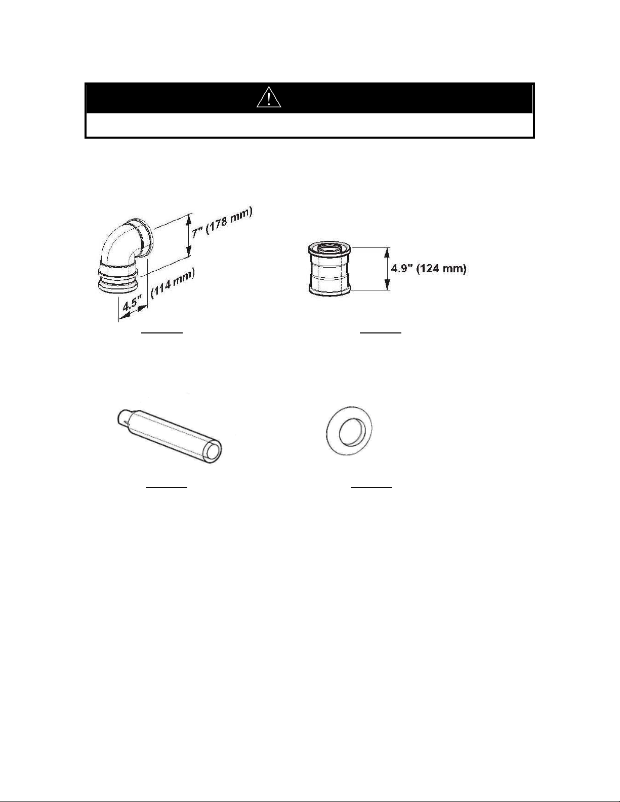
Components needed for direct vent applications:
Figure 19 Figure 20
1) horizontal discharge adapter 2) vertical discharge adapter
BWC p/n 239-44506-00 BWC p/n 239-44500-00
Figure 21 Figure 22
3) wall discharge terminal plate 4) rubber wall
Length = 12” (305mm)
BWC p/n 239-46848-00 Part of BWC vent kit
6
Page 7
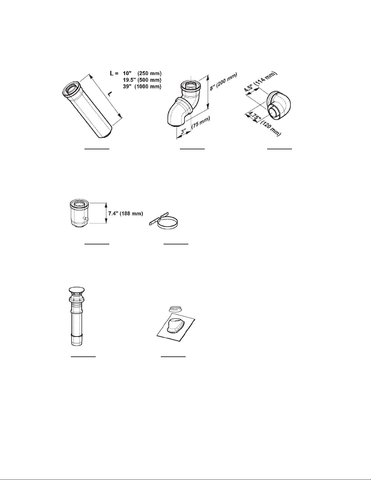
Figure 23 Figure 24 Figure 25
5) vent extension 6) 45º vent pipe elbow 7) 90 º vent pipe elbow
10” BWC p/n 239-44496-00 (sold in pairs only) BWC p/n 239-44499-00
19.5” BWC p/n 239-44497-00 BWC p/n 239-44495-00
39” BWC p/n 239-44498-00
Figure 26 Figure 27
8) condensate collector 9) vent pipe clamp
BWC p/n 239-44501-00 BWC p/n 239-44493- 00
Figure 28 Figure 29
10) vertical discharge roof terminal 11) pitch roof flashing
BWC p/n 239-44494-00 (1/12) BWC p/n 239-44502-00
(8/12) BWC p/n 239-44503-00
(6/12) BWC p/n 239-44504-00
7
Page 8

Figure 30 Figure 31
12) flat roof flashing 13) condensate trap kit
BWC p/n 239-44492-00
8
Page 9
Installation Instructions
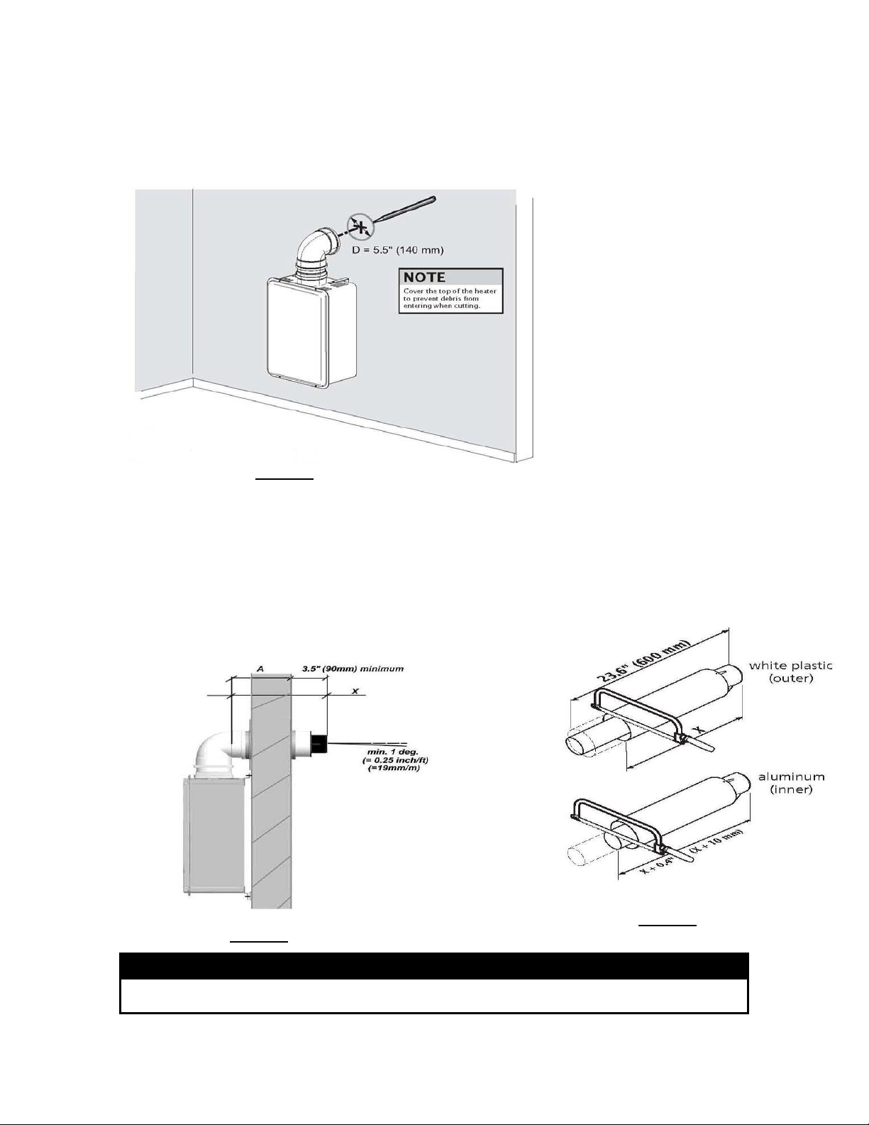
Everhot Horizontal Discharge Vent System
Identify the vent location
Steps:
- Place horizontal discharge adapter on water heater
- Mark position on wall
- Or use template provided with water heater
- Cut hole, covering the top of the water heater to prevent debris from entering
Figure 32
Measure dimension to fit
Figure 34
Figure 33
NOTICE
Note: if the vent system is shorter than 5 ft. (1,52 m) and no condensate collector is installed, be sure
to install the wall terminal with a 1° angle to the outside of the building.
9
Page 10
NOTICE
Note: 3.5” (90 mm) is the minimum outer cap length. If needed the length outside the wall may
exceed this dimension.
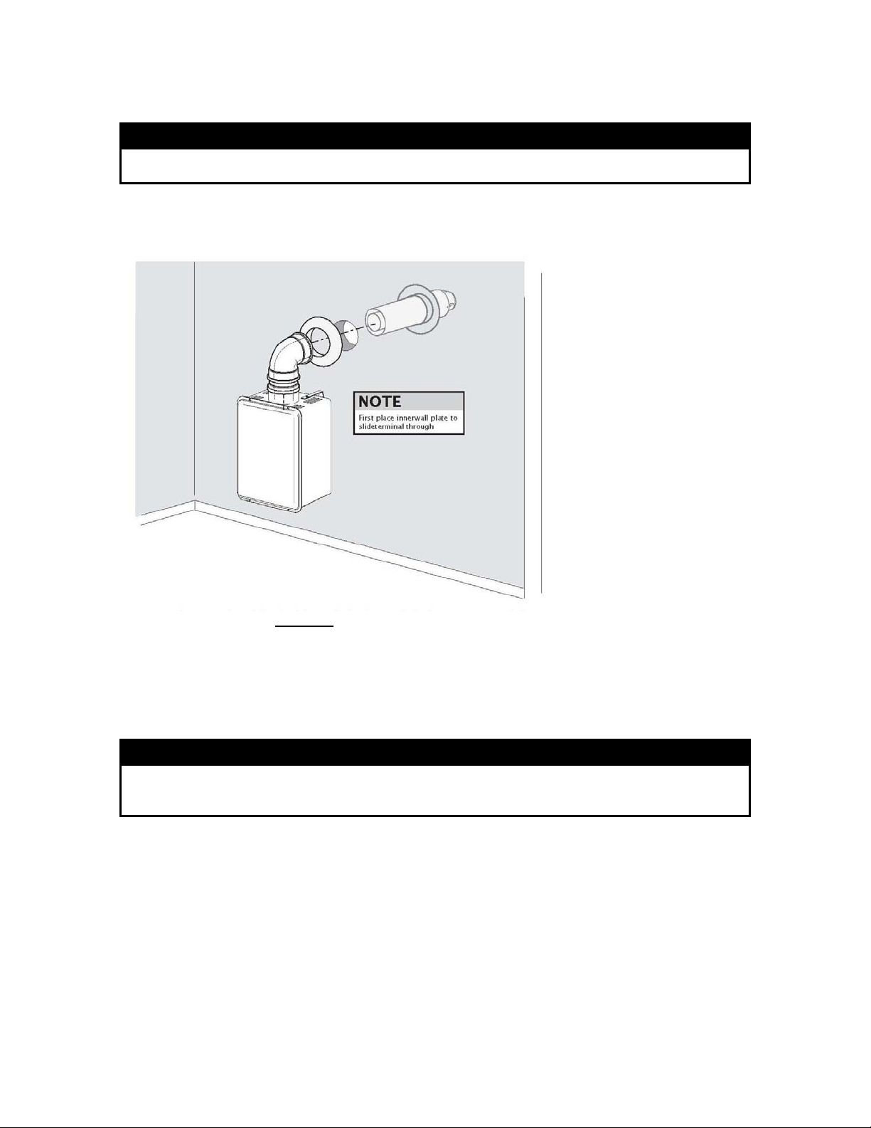
Final installation of the venting system
Figure 35
From the outside of the building, slide the wall discharge terminal through the vent wall passage. A
supplied rubber wall plate can be installed on the exterior of the building. Slide the inner wall plate onto the
terminal. If necessary apply silicon sealant to fill up spaces between vent terminal and the wall. Vent
connections must be firmly pressed together so that the gaskets form an airtight seal.
NOTE
When the total vent system length is greater than 5ft. (1,52 m), condensate will form which could damage
the water heater. For vent lengths greater than 5ft. (1,52 m), a condensate collector and trap must be
installed.
10
Page 11
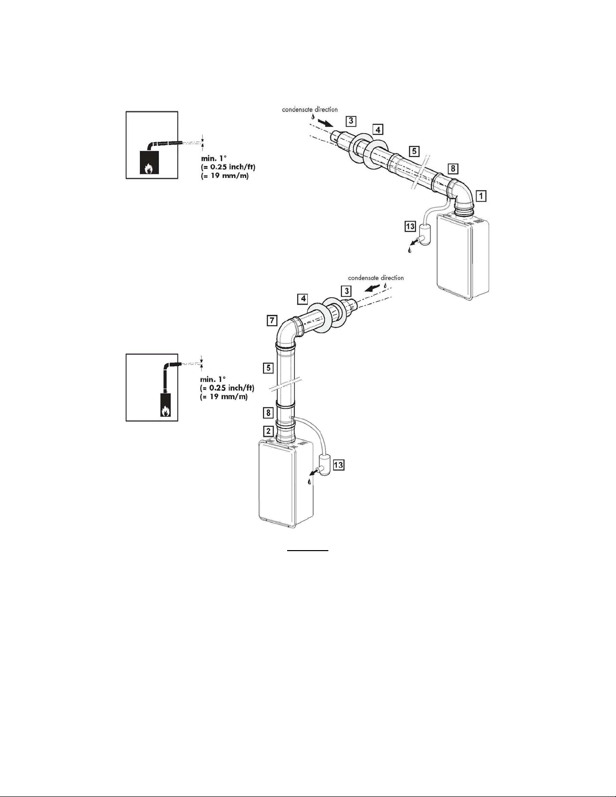
Horizontal Vent System
Installation examples
Figure 36
11
Page 12
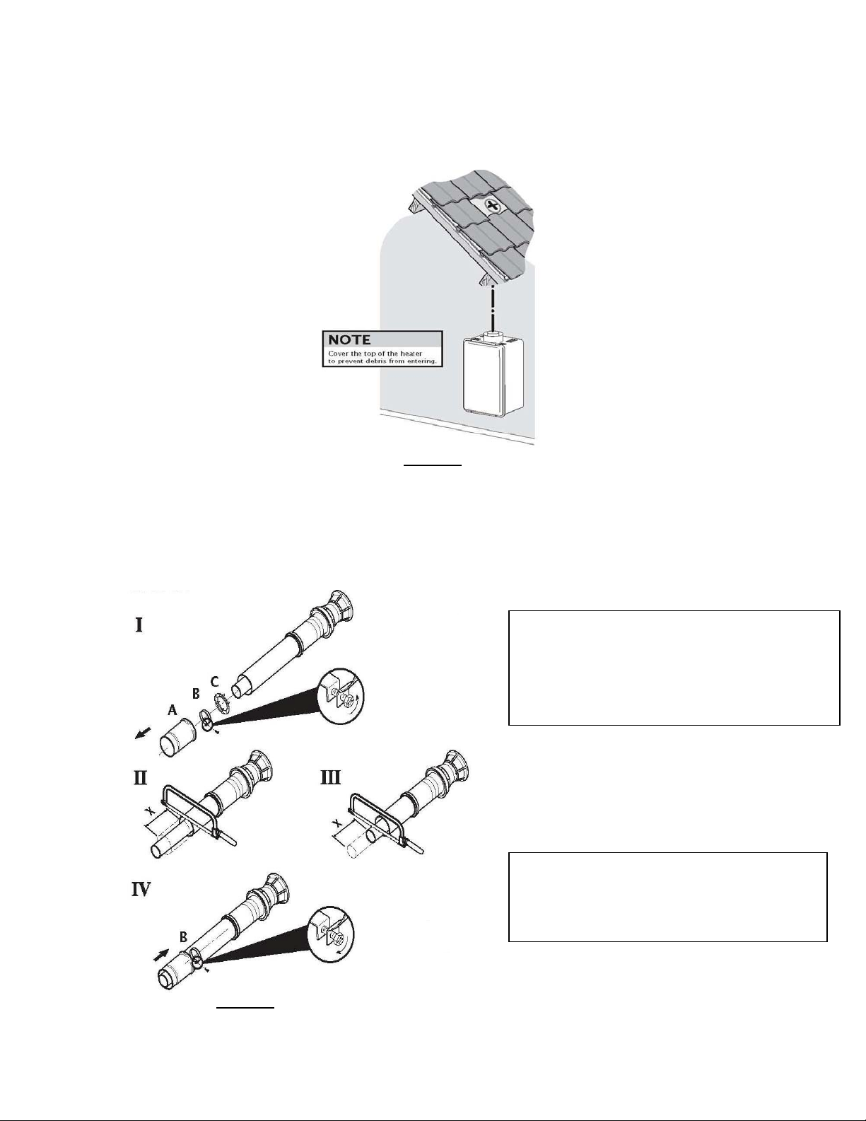
Installation Instructions
y
Everhot Vertical Discharge Vent System
Figure 37
Identify the vent location
Determine the location where the roof discharge terminal will be installed. Taking into account the angle of
the roof, cut the hole with a dimension that allows the vertical discharge roof terminal to be installed.
Cut to fit
The terminal can be shortened by
removing the components A+B+C,
and then shortening both the inside
and outside pipes with the same
length X.
Re-assemble the terminal by attaching
the components A, B, and C in the
correct order. Tighten component B
securel
.
Figure 38
12
Page 13
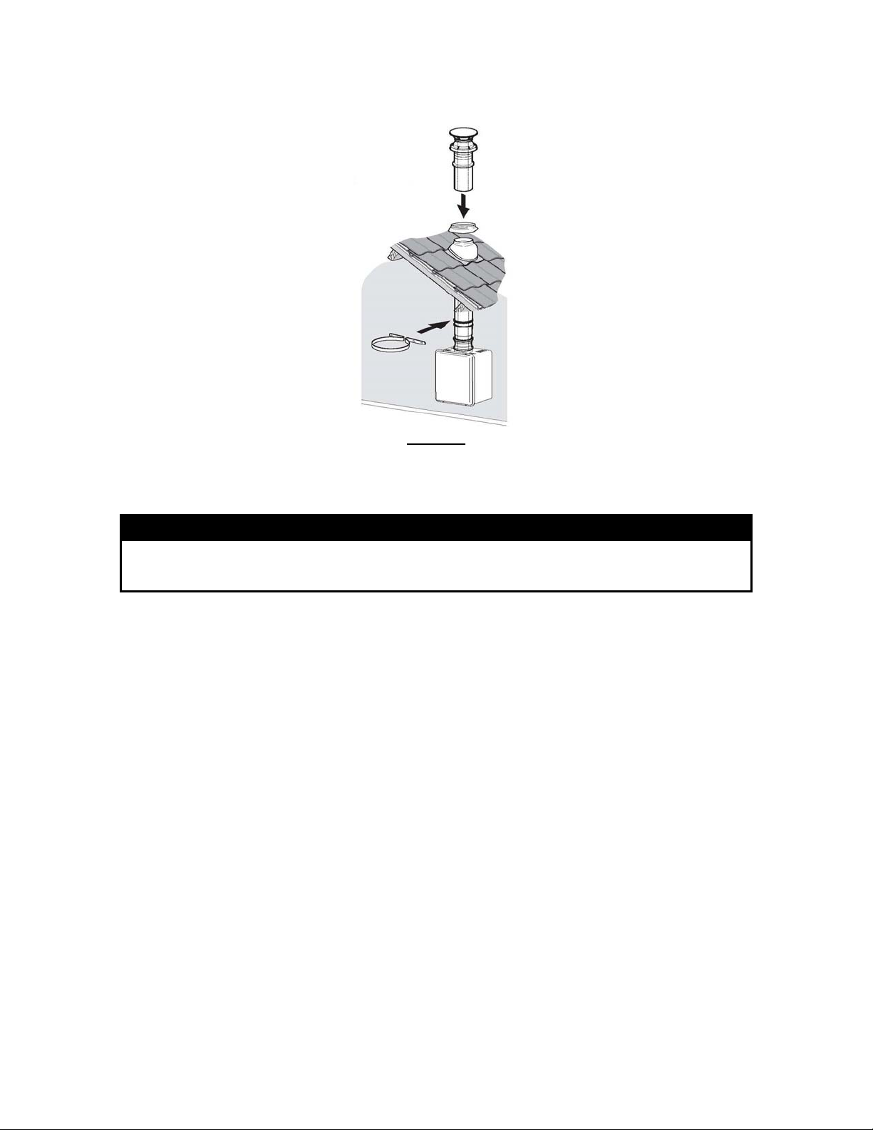
Mounting the vent system
Figure 39
Vent connections must be firmly pressed together so that the gaskets form an airtightseal. Secure the
system with the supplied vent pipe clamp or perforated hanger iron.
NOTE
When the total vent system length is greater than 5ft. (1,52 m), condensate will form which could damage
the water heater. For vent lengths greater than 5ft. (1,52 m), a condensate collector and trap must be
installed.
13
Page 14
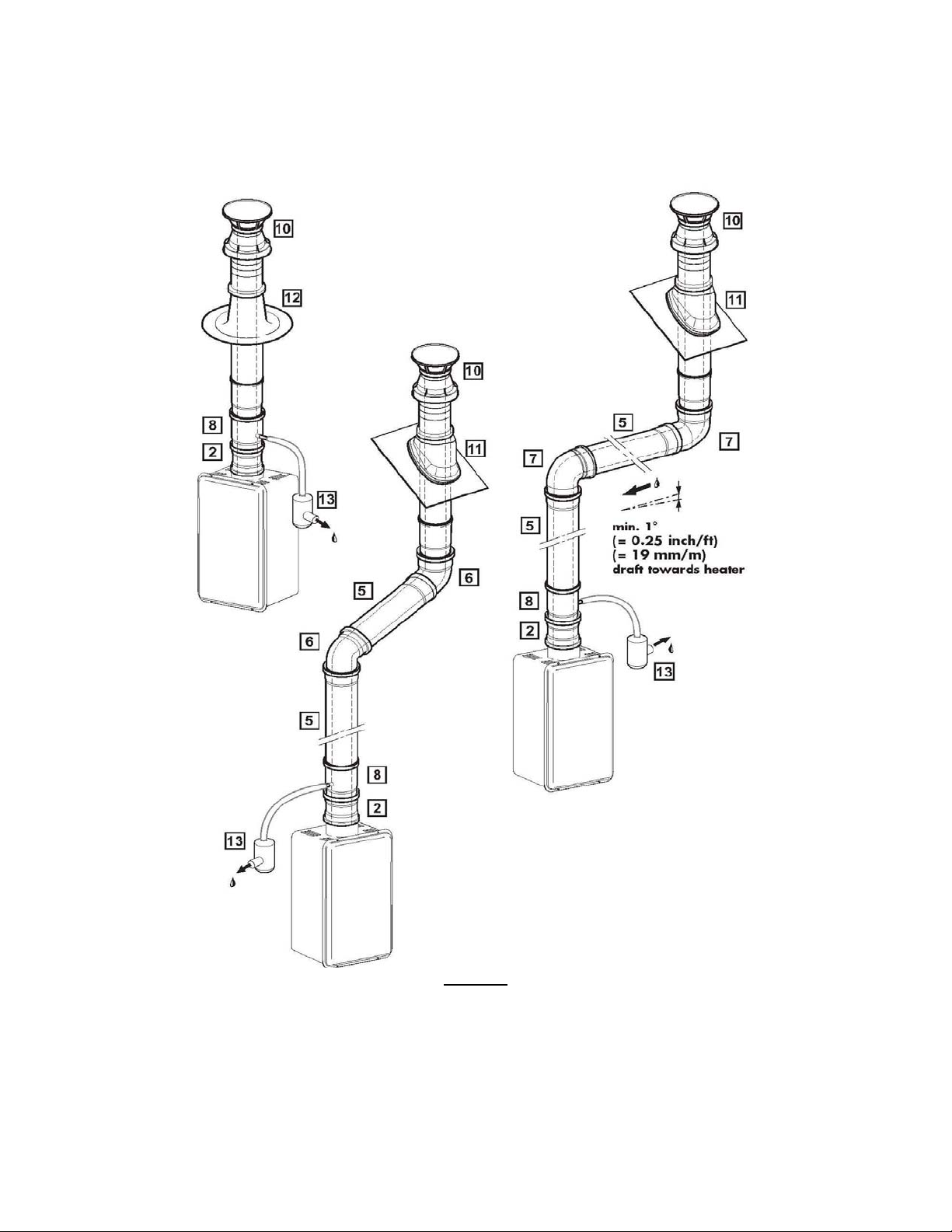
Vertical Vent System
Installation examples
Figure 40
14
Page 15
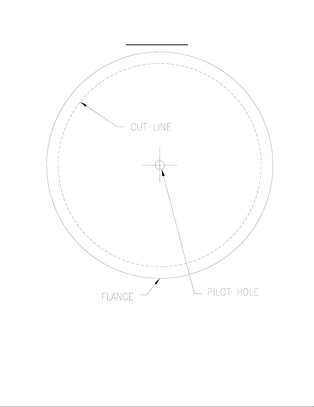
Cut Line Template
15
Page 16

800.900.9276 • Fax 800.559.1583 (Customer Service, Service Advisors)
20 Industrial Way, Rochester, NH 03867 • 603.335.6300 • Fax 603.335.3355 (Applications Engineering)
1869 Sismet Road, Mississauga, Ontario, Canada L4W 1W8 • 905.238.0100 • Fax 905.366.0130
www.Laars.com Litho in U.S.A. © Laars Heating Systems 0810 Document 11046
 Loading...