

Laars HWG-M2-150, HWG-M2-250, HWG-M2-175, HWG-M2-200 Installation, Operation And Maintenance Instructions
Installation, Operation and Maintenance Instructions Document 2108A
Installation,
Operation and
Maintenance
Instructions for
9600 HWG
Condensing Water
Heater for Natural Gas
or Propane
Models HWG-M2-150
HWG-M2-175
HWG-M2-200
HWG-M2-250
FOR YOUR SAFETY: This product must be installed and serviced by a professional service technician,
qualified in hot water heater installation and maintenance. Improper installation and/or operation could
create carbon monoxide gas in flue gases which could cause serious injury, property damage, or death.
Improper installation and/or operation will void the warranty.
WARNING
If the information in this manual is not followed exactly, a fire or explosion may result
causing property damage, personal injury or loss of life.
Do not store or use gasoline or other flamable vapors and liquids in the vicinity of this or any
other appliance.
WHAT TO DO IF YOU SMELL GAS
Do not try to light any appliance.
Do not touch any electrical switch; do not use any phone in your building.
Immediately call your gas supplier from a neighbor's phone. Follow the gas supplier's
instructions.
If you cannot reach your gas supplier, call the fire department .
Installation and service must be performed by a qualified installer, service agency or the
gas supplier.
10-427A

Page 2
LAARS HEATING SYSTEMS
TABLE OF CONTENTS
SECTION 1.
Introduction and Unpacking
1A. Special Installation Considerations............... 3
1B. Checklist of Materials Installer
Must Provide ................................................ 3
1C. Unpacking .................................................... 3
SECTION 2.
Locating and Clearances
2A. Locating the 9600 HWG ............................... 4
2B. Locating the Unit for Proper Venting
Distance from the Outside Wall or
Roof Termination .......................................... 4
2C. Locating Vent Openings on Outside Wall ..... 5
2D. Locating Unit for Proper Vent Height ............ 5
2E. Locating Unit with Respect to Ventilation ..... 5
2F. Locating Unit with Respect to
Storage Tanks .............................................. 5
SECTION 3.
Installation
3A. Installing Vent Piping Terminal ..................... 5
3B. Connecting Gas to the 9600
HWG Water Heater ...................................... 6
3C. Connecting Water System Piping,
Fittings & Accessories .................................. 6
3D. Tank Temperature Control ........................... 7
3E. Condensate Drain Connection ..................... 7
3F. Electrical Connections .................................. 7
3G. Main Power .................................................. 7
3H. Temperature Control .................................... 7
SECTION 4.
Start Up
4A. Filling the System ....................................... 10
4B. Operation Checklist .................................... 10
SECTION 5.
Maintenance
5A. Owner Care and Maintenance ................... 11
5B. Routine De-Liming Procedure .................... 11
5C. Therostat Replacement .............................. 11
5D. Vent and Condensate Drain Inspection
(performed annually) .................................. 11
5E. Cleaning Combustion Chamber Coil
and/or Burner ............................................. 12
5F. Combined Water (potable) Heating and
Space Heating ............................................ 12
SECTION 6.
Quick Reference Trouble Shooter
6A. Short Cycling .............................................. 13
6B. 9600 Overheats Quickly or
Knocks During Operation ........................... 13
6C. Delayed Ignition .......................................... 13
6D. Occasional Lockouts .................................. 13
S9301A Control Module ............................. 14
SECTION 7.
Replacement Parts List
................................................................... 17
To the Installer: After installation these instructions
must be given to the owner or left on or near the
Water Heater.
To the User: This booklet contains important
information that will help you in maintaining and
operating this Water Heater. Please retain it for
future reference.
Warning: Should overheating occur or the gas
supply fail to shut off, turn off the manual gas
control valve to the appliance.
Important: This unit must be installed in accordance
with state and local codes by a qualified installer!

9600 HWG Water Heater
Page 3
SECTION 1.
Introduction & Unpacking
1A. Special Installation Considerations
BEFORE YOU BEGIN:
It is important for you to take a few minutes to
review this Installation and Operating Instructions
manual before you begin installation. This will make
installing and operating the unit easier and faster.
Direct vent-sealed combustion.
The 9600 HWG Water Heater does not and
should not take combustion air from inside the
building. All of the air is drawn in from the outdoors
through a 3-inch diameter plastic pipe. 3" PVC, ABS
or CPVC pipe is used for air intake and exhaust
venting. (PVC not permitted on HWG-M2-250
exhaust)
No chimney......flue......or draft inducer required.
Because this is a sealed combustion, forced draft unit,
it does not require, and must not be connected to a
chimney, existing venting system, or draft inducer.
CAUTION
Connection of this vent to a chimney, existing
venting system, or draft inducer will result in
poor and possibly dangerous operation.
The supplied vent terminations are designed to
be installed through the nearest outside wall (see
Sections 2C and 2D).
The 9600 HWG Water Heater is protected
against over pressurization. A 150 PSI pressure relief
valve is fitted to the unit. It is installed in the
dedicated fitting on the top of the water heater.
IMPORTANT: The inlet gas pressure to the
appliance must not exceed 13" WC.
A high quality circulator is built into the 9600
HWG Water Heater and will provide sufficient head
pressure and volume to circulate water to the storage
tank(s) (see Table 3).
All installations must be made in accordance
with the: 1) American National Standard Z223.1Latest Edition National Fuel Gas Code and with the
requirement of the local utility or other authorities
having jurisdiction, or; 2) Can-CGA B149 installation
code and / or local installation codes.
Such applicable requirements take precedence
over the general instructions contained herein.
All electrical wiring is to be done in accordance
with local codes, or in the absence of local codes,
with: 1) the National Electrical Code ANSI/NFPA
No. 70-latest Edition, or; 2) CSA standard C22.1
Canadian Electrical Code - Pt 1. This appliance
must be electrically grounded in accordance with
these codes.
1B. Checklist of Materials Installer
Must Provide
1. The following are acceptable materials for intake
and exhaust vents:
a) 3" or 4" PVC sched. 40 pipe per ASTM D-
1785 standard. (Not permitted on HWG250 exhaust).
b) 3" or 4" PVC DWV pipe per ASTM D-
2665 standard. (Not permitted on HWG250 exhaust).
c) 3" or 4" ABS-DWV pipe per ASTM D-
2661 or ASTM F-628 Standard.
d) 3" or 4" CPVC schedule 40 pipe per ASTM
F441 standard.
e) The solvent cement for pipe joints is to
comply with the following standards:
1). PVC pipe D2564
ABS pipe D2235
CPVC pipe F493
2). CSA listed solvent for a-d
2. Electrical connection to a 120VAC/15Amp
service.
3. Gas connection that will provide 250 cubic feet/
hour at 4 to 13 inch water gauge pressure.
4. Condensate drainage: a floor drain is preferred a condensate pump may be used.
5. Miscellaneous copper fittings and bronze valves
will be required to complete the piping system.
1C. Unpacking
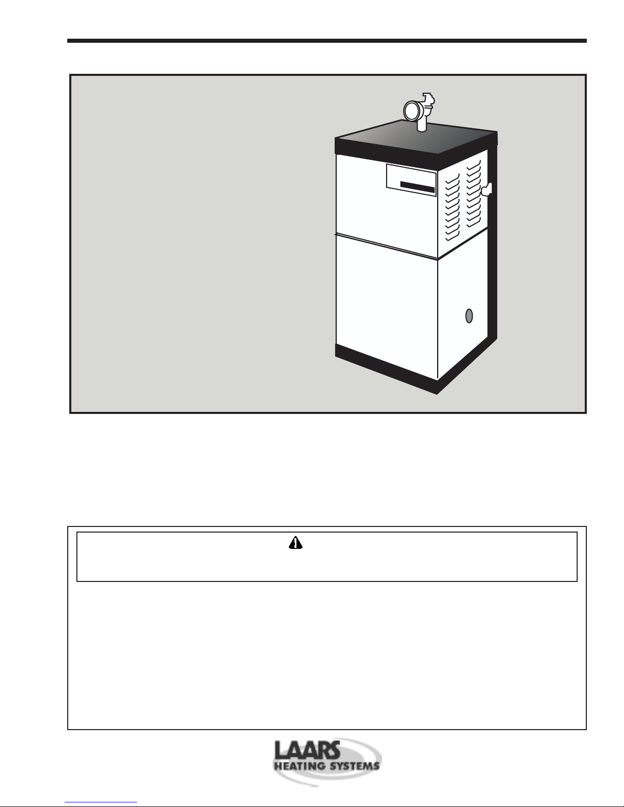
The 9600 HWG Water Heater is shipped in a
single carton with the following standard components
on top of the unit (see Figure 1).
1) Exhaust terminal
2) Intake terminal
3) Vent terminal backing plate (4)
4) Hubless coupling reducer
5) Hubless coupling (2)
Figure 1. Contents of shipping package.
1. Remove all packing and tie-down materials.
2. Check contents of the carton against items
shown above.
Page 4
LAARS HEATING SYSTEMS
SECTION 2.
Locating and Clearances
2A. Locating the 9600 HWG
The appliance should be located in an area where
leakage of any connections will not result in damage
to the area adjacent to the appliance or to lower floors
of the structure.
When such a location is not available, it is
recommended that a suitable drain pan, adequately
drained, be installed under the appliance.
The unit is design certified by AGA / CGA for
installation on combustible flooring; in basements; in
closets, utility rooms or alcoves. It must not be
installed on carpeting.
The location for the unit should be chosen with
regard to the vent pipe lengths, external plumbing,
ventilation of operating components and accessibility
for service and cleaning.
If there is potential for snow accumulation in your
area, both the vent terminals should be installed at an
appropriate level above grade (see Figures 2 and 3).
The following dimensions and requirements
should be met when choosing the location for the unit
(see Table 1):
Minimum Recommended
Clearances Clearance for
From Accessibility
Combustible and Venting
Construction
BOTH AGA CGA
Left Side 1" 6" 48"
Right Side (Controls) 1" 12" 24"
Top 1" 14" 24"
Back 1" 9" 24"
Front 1" 24" 48"
Vent 0"
Table 1. Location clearances.
2B. Locating the Unit for Proper Venting
Distance from the Outside Wall or
Roof Termination
Intake Exhaust
Maximum run: Maximum run:
3" pipe size 3" pipe size
55 equivalent feet 55 equivalent feet
4" pipe size 4" pipe size
85 equivalent feet 85 equivalent feet
Minimum run: Minimum run:
11 equivalent feet 21½ equivalent feet
Intake Terminal is Exhaust Terminal is
P/N 2400-102. P/N 2400-104.
Equivalent feet is determined by adding 10 linear
feet for each 90° elbow and 5 linear feet for each 45°
elbow to be installed to the actual linear feet of pipe
required.
Example: 8' of pipe, 2 x 45° elbows and a 90°
elbow.
Equivalent Feet: 8' + (2 x 5') + (1 x 10') = 28.
If a 4" pipe size is used to permit longer vent
runs the installer must supply 4" hubless couplings (2)
and 3 x 4 bushings (2) to adapt to the unit fittings. 4"
inlet and exhaust screens are provided for installation
in contractor provided 4" coupling and elbow
terminations.
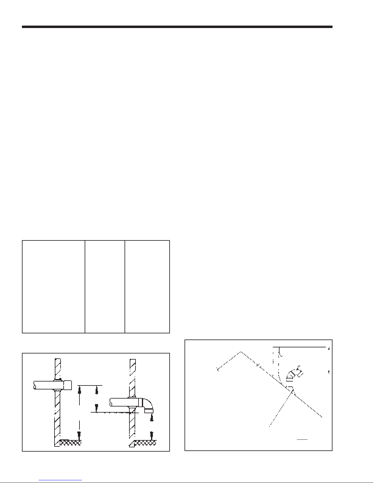
NOTE: It is required that a minimum separation
of 18" be maintained between the intake and exhaust
terminals and that both terminals be installed on the
same wall of the building. The intake terminal must
not be installed above the exhaust terminal since this
would tend to pull exhaust gases back into the intake
(see Figures 2 and 3).
Exhaust
6"
Inside of
Exterior
Wall
Figure 2. Suggested vent terminal installations.
24"
Min.
Grade Level
Intake
12" Min.
Exhaust
Terminal
Terminal
NOTE: If flue passes through a flat
roof with parapet walls exhaust terminal
level must be above the level of the wall.
If flue passes through a sloped or
peaked roof it is not necessary to locate
it to conform with location requirements
for conventional chimneys.
Typical Soil Pipe
Flashing Acceptable
Figure 3. Alternate vent terminal installations.
Roof terminals for air
intake must prevent
entry of rain water.
Intake
18"
Min.

9600 HWG Water Heater
Page 5
2C. Locating Vent Openings on Outside Wall
1. Exhaust terminal location.
The exhaust terminal fitting requires a 4" (10cm)
diameter hole through the outside wall. The
center line of this opening must be at least 16"
(41cm) above grade and at least 14" (35.6cm)
from any other building opening such as doors,
windows, etc.
Vent opening should be well away from
shrubbery or other obstructions that would block
or restrict the exhaust.
Whenever possible, locations under windows or
near doors should be avoided. Steaming at the
flue terminal is a normal occurrence. This should
be considered when deciding flue terminal
position.
2. Intake terminal location.
The intake terminal requires a separate 4" (10cm)
diameter hole to install the intake fitting. The
center line of the hole should be at least 16"
(41cm) above grade outdoors and 18" (46cm)
away from the exhaust outlet. The intake should
never be located above the exhaust terminal.
3. Intake and exhaust location for multiple unit
installation. For the installations of multiple
units, refer to Figure 4 for intake and exhaust
terminal locations.
2D. Locating Unit for Proper Vent Height
The vent locations you select must permit direct
pipe runs to the terminal from the boiler. Since the
9600 HWG Water Heater is designed to drain any
water that collects in the vent, it is important that you
do not build any traps or low points into the vent
where water could collect and restrict the vent. It is
recommended that 1/4" per foot of vent be built into
the vent system to direct any water in the vent back
toward the boiler. Note that standard DWV elbows
have a built in allowance for the required 1/4" per foot
pitch.
2E. Locating Unit with Respect to Ventilation
While the 9600 HWG Water Heater requires no
indoor air for combustion, adequate airflow around the
unit must be provided for proper cooling of electrical
components.
EXHAUST
INTAKE
Figure 4. Multiple units minimum vent terminal
separation.
2F. Locating Unit with Respect to
Storage Tanks
For the best results the 9600 HWG Water Heater
should be located within 10 feet of the storage tanks.
If the unit must be installed with longer piping
runs, then the larger diameter tubing must be used.
Calculate the necessary pipe size for your installation
(see Table 2).
SECTION 3.
Installation
3A. Installing Vent Piping Terminal
The water heater is provided with intake and
exhaust terminals for use with 3" diameter plastic
pipe.
The installer is responsible for obtaining the vent
pipe and fittings. The maximum combined length of
the intake and exhaust pipe and maximum number of
elbows are determined by using the guidelines on Page
4.
The following steps are recommended for vent
installation:
1. Obtain the necessary 3" or 4" diameter plastic
piping and fittings as determined beforehand.
2. Position unit at previously selected location.
3. Unpack vent terminals and vent terminal backing
plates.
4. Cut holes in outside wall for vent terminals in the
previously selected locations.
5. Mount the vent terminals backing plates.
6. Fit all of the vent pipes together without
cementing. Make sure that there are no water
traps and that any pitch is inclined back towards
the boiler.
7. Make sure that the flexible vent connections at
the unit fit properly.
8. Begin cementing the intake and exhaust pipes,
start at the vent terminals and work back towards
the appliance. Note that the intake terminal is a
90 degree elbow fitting that is designed to face
down.
9. Support both intake and exhaust pipes with
hangers.
DO NOT RELY ON 9600 HWG TO SUPPORT
PIPES.
Horizontal runs must be supported adjacent to
each fitting and at 5ft. intervals between fittings.
ABS pipe must be supported at 3ft. intervals.
10. Tighten the flexible couplings to connect the
water heater to the vent pipes.
Page 6
LAARS HEATING SYSTEMS
3B. Connecting Gas to the 9600 HWG
Water Heater
1. The water heater requires gas at an inlet gas
pressure of at least 4" WC and no greater than
13" WC. Check with your local gas utility or
supplier for availability of these delivery
pressures.
2. Referring to TABLE 2, size supply piping to
keep flow capacity to the unit above 250 cubic
feet per hour (CFH) per unit installed.
3. Run gas supply line in accordance with all
applicable codes.
4. Locate and install manual shutoff valves in
accordance with state and local requirements.
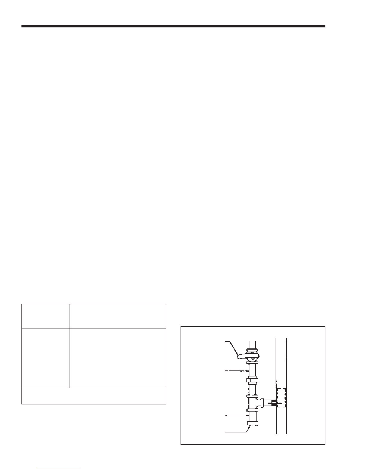
5. Install drip leg and ground joint union
(see Figure 5).
6. All threaded joints should be coated with piping
compound resistant to action of liquefied
petroleum gas.
7. The 9600 HWG unit and its individual shutoff
valve must be disconnected from the gas supply
piping during any pressure testing of that system
at test pressures in excess of 1/2 psig (3.45kpa).
It must be isolated from the gas supply system by
closing its individual manual shutoff valve
during any pressure testing of the gas supply
piping system at test pressures equal to or less
than 1/2 PSIG (3.45kpa).
Failure to do so will possibly result in damage to
the gas control system.
8. The 9600 HWG Water Heater and its gas
connections must be leak tested before placing
the unit in operation.
9. Purge all air from gas lines.
Length Capacity of Pipe in MBTU/h
of (.6 Specific Gravity)
Pipe 3/4" 1" 1-1/4"
10' 278 520 1,050
20' 190 350 730
30' 152 285 590
40' 130 245 500
50' 115 215 440
75' 93 175 360
100' 79 150 305
150' 64 120 250
Additional length to be added for each tee or bend:
1.7' 2.2' 2.7'
Table 2. Gas supply piping.
3C. Connecting Water System Piping,
Fittings & Accessories
Installing tank & piping
The 9600 HWG can be used with several
different types of readily available storage tanks. A
bronze circulating pump is built into the appliance.
The pump draws water from the storage tank and
pumps the water through the heater and back into
the tank.
Position the storage tank(s).
At the previously selected locations, position the
storage tank(s). Use Table 3 to determine the pipe size
necessary to provide adequate flow between the 9600
HWG and the tank(s).
Hot water outlet piping, fittings, and accessories.
1. Begin piping to the tank from the hot water
outlet at the top of the 9600 HWG cabinet.
2. Pipe the outlet from the relief valve (located on
top of the unit) such that any discharge from the
relief valve will be conducted to a suitable place
for disposal when relief occurs. Do not reduce
line size or install any valves in this line. The
line must be installed to allow complete drainage
of both the valve and the line.
3. Install a shut off valve in the piping between the
thermometer fitting and the tank.
Cold water supply piping, fittings and accessories.
1. Install a strainer between the 9600 HWG and the
system. For proper pipe size and distance
limitations, refer to Table 3.
2. Connect a drain valve and a shut off valve to the
9600 HWG cold inlet. On multiple units install a
check valve at each units cold water inlet.
3. Where check valves have been installed on cold
water inlet piping, check to be sure system has
an adequately sized expansion tank to allow
thermal expansion to occur.
Hot water supply piping.
Follow the manufacturers guidelines for
completion of the hot water system connections.
Manual Main
Shut Off
Gas Supply
To
9600 HWG
Drip Leg
Cap
Figure 5. Gas supply piping.
 Loading...