

Page 1
Installation and Operation Instructions Document 1 1037
A SPANISH LANGUAGE VERSION OF THESE INSTRUCTIONS IS AVAILABLE
BY CONTACTING THE COMPANY LISTED ON THE RATING PLATE.
TM
LAARS® Multi-Flue
Commercial Energy Saver Oil-Powered Water Heater
Models CF-38-3, CF-80-3, CF-100-3
LA VERSION ESPANOLA DE ESTAS INSTRUCCIONES SE PUEDA OBTENER AL
ESCRIBIRLE A LA FABRICA CUYO NOMBRE APPRECE EN LA PLACA DE
ESPECIFICACIONES.
WARNING: IF THE INFORMATION IN THESE INSTRUCTIONS IS NOT
FOLLOWED EXACTLY, A FIRE OR EXPLOSION MAY RESULT CAUSING
PROPERTY DAMAGE, PERSONAL INJURY OR DEATH
WARNING:
Do not store or use gasoline or other flammable vapors, liquids or materials
in the vicinity of this or any other appliance
WARNING:
Improper installation, adjustment, alteration, service or maintenance can result
in injury or property damage. For assistance or additional information, please
contact the plumbing professional who installed this water heater.
Notice To The Installer: Before connecting this appliance, please read these
instructions carefully, we call your attention to all items, specifically the
instructions on locating the water heater.
Notice To The User: Before operating this appliance, please read these
instructions thoroughly. Then please refer to this manual for future reference.
WARNING:
Be aware that this water heater is capable of producing hot water at a
temperature high enough to cause scalding injury. Water temperature over
125°F can cause severe burns or death from scalds. Please read these
instructions carefully before operating this unit.
800.900.9276 • Fax 800.559.1583 (Customer Service, Service Advisors)
20 Industrial Way, Rochester, NH 03867 • 603.335.6300 • Fax 603.335.3355
1869 Sismet Road, Mississauga, Ontario, Canada L4W 1W8 • 905.238.0100 • Fax 905.366.0130
www.Laars.com Litho in U.S.A. © Laars Heating Systems 0806 Document 11037
Page 2

TABLE OF CONTENTS
General Information.................................................................................. 3
Installation ................................................................................................. 3
Locating the water heater.................................................................. 3
Minimum clearances .......................................................................... 3
Combustion air supply....................................................................... 4
Electrical connections........................................................................ 5
Venting................................................................................................. 6
Water connections.............................................................................. 6
Installation for potable water and space heating .................................. 8
Oil tanks and piping.................................................................................. 9
Operation ...................................................................................................10
Burner and thermostat information ........................................................11
Maintenance...............................................................................................15
CONGRATULATIONS!
You have just purchased one of the finest water heaters on the
market today!
This installation, operation and instruction manual will explain in
detail the installation and maintenance of your new Oil-Fired Water
Heater. We strongly recommend that you contact a plumbing
professional for the installation of this water heater.
We require that you carefully read this manual, as well as the
enclosed warranty, and refer to it when questions arise. If you have
any specific questions concerning your warranty, please consult the
plumbing professional from whom your water heater was
purchased. For your records we recommend that you write the
model, serial number and installation date of your water heater in the
maintenance section in the back of this manual.
This manual should be kept with the water heater.
2
Page 3

General Information
Note: It is recommended that the installation and service of this water heater be
performed by a plumbing professional.
This water heater must be installed in accordance with local codes. In the absence of
local codes, it must be installed in compliance with the National Fire Protection
Standard For Oil Burning Equipment NFPA No. 31 (latest edition). In Canada the
installation of this water heater shall be in accordance with the regulation of authorities
having jurisdiction and CSA STANDARD B139.
The warranty of this water heater is in effect only when the water heater is installed,
adjusted, and operated in accordance with these installation and operating instructions.
DO NOT use this appliance if any part has been submerged in water. You should
contact the plumbing professional who installed the water heater to inspect the
appliance and to replace any part of the control system and any component which has
been submerged in water.
A sacrificial anode is used to extend tank life. The removal of this anode, for any
reason, will nullify the warranty. In areas where water is unusually reactive, an odor
may occur at the hot water faucet due to a reaction between the sacrificial anode and
the impurities in the water. If this should happen, an alternative anode may be
purchased from the supplier that sold you this water heater. This will minimize the odor
while protecting the tank. Additionally, the water heater should be flushed with
appropriate dissolvers to eliminate any bacteria.
INSTALLATION
Locating the water heater
The location of this water heater is of the utmost importance. Before installing the water
heater, you should select a location where the floor is level and is easily accessible to
water supply lines as well as to a chimney or vent. DO NOT locate the water heater
where water lines could be subjected to freezing temperatures.
This water heater MUST be installed indoors out of the wind and weather.
Note: For California installation this water heater must be braced, anchored, or
strapped to avoid falling or moving during an earthquake. See instructions for
correct installation procedures. Instructions may be obtained from California
Office of the State Architect, 400 P Street, Sacramento, CA 95814.
Minimum Clearances
This water heater shall be installed on NON-COMBUSTIBLE flooring only. This water
heater may be installed in an alcove. Refer to the marking on the front of the water
heater for clearances to combustible materials.
The installation should allow access to the front of the water heater and adequate
clearance should be provided for servicing and operating the water heater. It is
recommended that a minimum clearance of 3” be provided on the side of the water
heater for servicing and maintenance of the temperature and pressure relief valve.
3
Page 4

Installation (locating the water heater) continued-
This water heater must be located in an area where leakage of the tank or water line
connections will not result in damage to the area adjacent to the water heater or to
lower floors of the structure. When such locations cannot be avoided, a suitable drip
pan must be installed under the water heater. The drain pan must have a minimum
length and width of at least 4 in. (10.2 cm) greater than the diameter of the water
heater and must not restrict proper combustion air flow to the water heater. The drain
pan, as described above, can be purchased from your plumbing professional. The
piping must be at least ¾” in diameter and pitched for proper drainage. The pan must
not restrict the combustion airflow.
WARNING
Water heaters are heat-producing appliances. To avoid damage or injury,
there shall be no materials stored against the water heater. Proper care shall
be taken to avoid unnecessary contact (especially by children) with the water
heater. UNDER NO CIRCUMSTANCES SHALL FLAMMABLE MATERIALS,
SUCH AS GASOLINE OR PAINT THINNER, BE USED OR STORED IN THE
VICINITY OF THIS WATER HEATER OR IN ANY LOCATION FROM WHICH
FUMES COULD REACH THE WATER HEATER.
Note: The failure to adhere to these instructions may create a hazard to life
and property and will nullify the warranty.
Water heater corrosion and component failure can be caused by heating and
breakdown of airborne chemical vapors. Examples of typical compounds that
are potentially corrosive are: spray can propellants, cleaning solvents,
refrigeration and air conditioning refrigerants, swimming pool chemicals,
calcium and sodium chloride, waxes and process chemicals. These materials
are corrosive at very low concentration levels with little or no odor to reveal
their presence.
NOTE: DAMAGE TO THE WATER HEATER CAUSED BY EXPOSURE TO
CORROSIVE VAPORS IS NOT COVERED BY WARRANTY.
IMPORTANT!!
THE FLOW OF COMBUSTION AND VENTILATING AIR MUST NOT BE
OBSTRUCTED!!
Combustion Air Supply
Installation of this water heater requires that provisions be made to supply
adequate air for combustion and ventilation. If the building is unusually tight
or if this water heater is installed in a small room, provisions for additional
makeup air must be provided. This air must be supplied through two
permanent openings located so that the lower edge of the lower opening is 6
inches below the top of the enclosure.
The minimum free air area for such openings shall not be less than one
square inch per 1000 BTU/HR of the total input rating of all appliances in that
enclosure of 100 square inches, whichever is greater. For outside air, in the
absence of local codes, refer to the National Fire Protection Standard For Oil
Burning Equipment NFPA No. 31 (latest edition).
4
Page 5
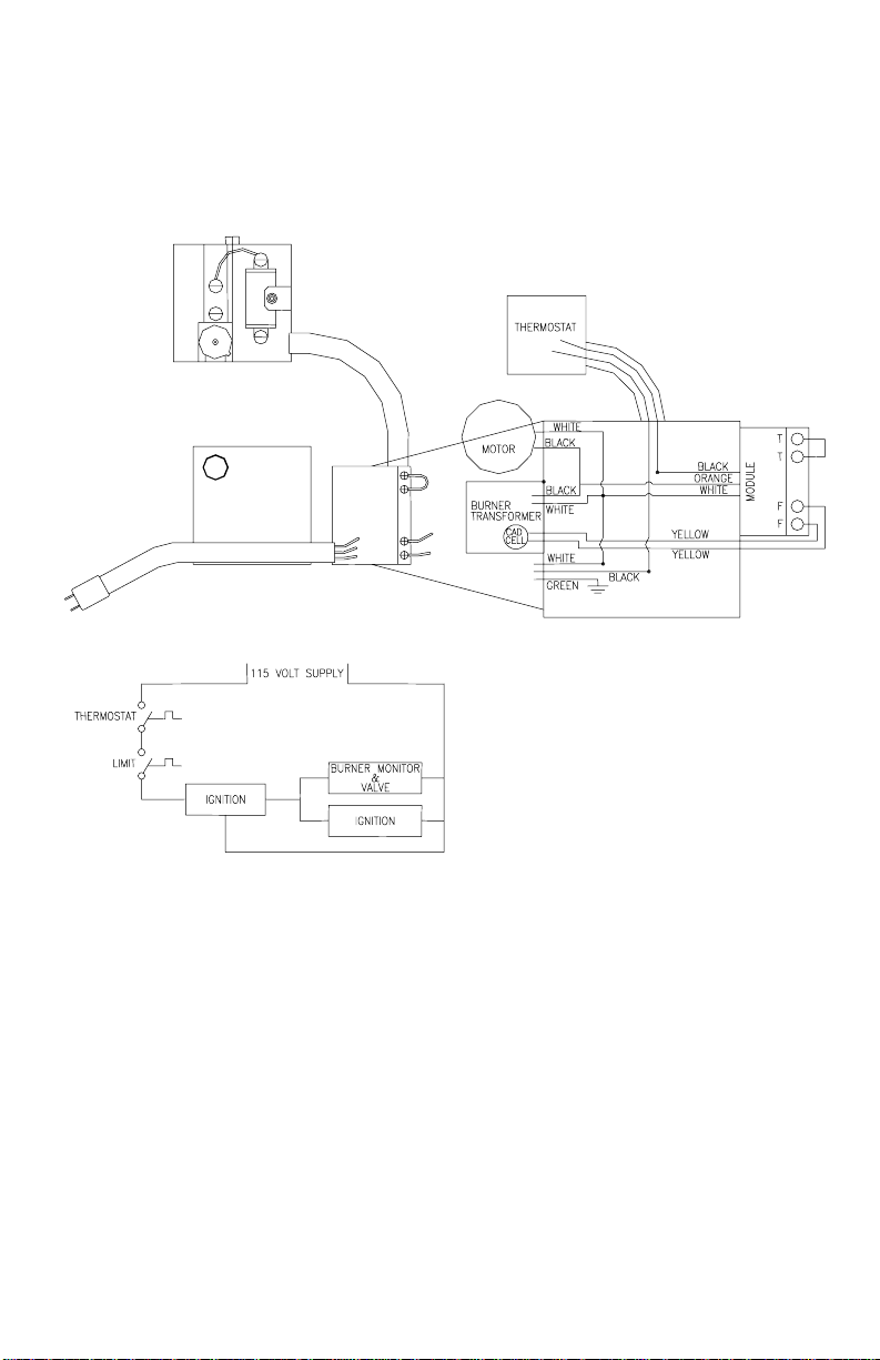
Electrical Connections
This water heater is normally wired for 120 volts and shall be electrically
grounded in accordance with local codes, or in the absence of local codes,
with the National Electrical Code, ANSI/NFPA No. 70 (latest Edition).
If any of the original wiring must be replaced, replacement shall be with 105
degree C wire or equivalent.
Figure 1
5
Page 6

Venting
The connection from the water heater vent to the stack must be made as
direct as possible and of the same diameter as the vent outlet. The
recommended slope of any horizontal breaching is at least 1/2" rise per
linear foot. A barometrically operated draft regulator (barometric damper)
shall be installed in the vent connector at a location just above the water
heater.
Caution: The stack must extend at least three feet above the highest point of
the roof to insure proper venting. The stack should be provided with a weather
cap of approved design.
Note: Provisions shall be made to prevent contact of the vent pipe with
combustible materials in accordance with all codes and regulations.
A separate vent for each appliance is strongly recommended. A separate
vent is required for installation and application of multiple power vent(s). If
combined venting of multiple appliances is necessary or if an unusual
situation arises consult the National Fire Protection Standard For Oil Burning
Equipment NFPA NO.31 (latest edition), for sizing and installation information.
Water Connections
NOTE: Before proceeding with the installation, close the main water supply
valve. After shutting off the main water supply, open and close the appropriate
faucets and valves to prevent any water from leaking out of the pipes while
making the water connections to the water heater. The cold water inlet and
hot water outlet are identified on the top of the water heater. The fittings at
the cold water inlet and hot water outlet are dielectric fittings with a 3/4 NPT
male thread. Make the proper plumbing connections between the water
heater and the plumbing system of the house. A shut-off valve should be
installed in the cold water supply line.
If sweat fittings are to be used, Do Not apply heat to the nipples on top of the
water heater. Sweat the tubing to the adapter before fitting the adapter to
water connections. It is imperative that no heat be applied to nipples
containing a plastic liner. Heat traps may have been provided in the inlet and
outlet nipples. Although they may appear to be plastic plugs, Do Not attempt
to remove the plastic insert.
If this water heater is installed in a closed water system, such as one having
a back-flow preventer in the cold water supply, provisions shall be made to
control thermal expansion. Your water supplier or local plumbing inspector
should be contacted on how to control this situation.
6
Page 7

Water Connections continued-
WARNING
For protection against excessive temperature and pressure, install
temperature and pressure protective equipment required by local codes, but
no less than a combination temperature and pressure relief valve certified as
meeting the requirements for Relief Valves and Automatic Gas Shut-off
Devices for Hot Water Supply Systems, ANSIZ21.22, by a nationally
recognized testing laboratory that maintains periodic inspection of production
of listed equipment or materials. The temperature and pressure relief valve
shall be marked with a maximum set pressure not to exceed the maximum
working pressure of the water heater. The temperature and pressure relief
valve shall also have an hourly rated temperature steam BTU discharge
capacity not less than the hourly rating of the water heater.
Install the temperature and pressure relief valve into the opening provided and
marked for this purpose on the water heater. Install a drainpipe in the opening
of the temperature and pressure relief valve so that any discharge from the
valve will exit within 6 inches above, or at any distance below the structural
floor and cannot contact any live electrical part. The end of the relief valve
drainpipe opening should terminate near the floor drain or other suitable
location. Do not subject the discharge opening to blocking or freezing or
reduce its size under any circumstances. It is recommended that a minimum
clearance of 3" be provided on the side of the water heater for servicing and
maintenance of the temperature and pressure relief valve.
After the installation of all the water lines, open the main water supply valve
and fill the water heater. Open several hot water faucets to allow air to escape
from the system while the water heater is filling. When a steady stream of
water passes through the faucets, close them and check all connections for
possible leaks in the system.
FAILURE TO INSTALL AND MAINTAIN A NEW, LISTED 3/4 X 3/4
TEMPERATURE AND PRESSURE RELIEF VALVE WILL RELEASE THE
MANUFACTURER FROM ANY CLAIM WHICH MIGHT RESULT FROM
EXCESSIVE TEMPERATURES AND PRESSURES.
Never operate the water heater without first being certain it is filled with
water.
This water heater can deliver scalding water temperatures at any faucet in the
system. Be careful whenever using hot water to avoid scalding injury. Certain
appliances require increased water temperatures (such as dishwashers and
automatic clothes washers). By setting this water heater to a higher water
temperature setting, you may create the potential for a scalding injury. To
protect against injury, install an anti-scalding tempering valve in the water
system. This valve will reduce point of discharge temperature by mixing cold
and hot water in branch water lines. Such valves are available from the local
plumbing supplier. Please consult the plumbing professional who installed the
water heater concerning this matter.
7
Page 8
THE FOLLOWING INSTRUCTIONS ARE FOR INSTALLATION OF:
GAS WATER HEATERS SUITABLE FOR WATER (POTABLE)
HEATING AND SPACE HEATING
THE COIL PROVIDED IN THIS WATER HEATER IS MANUFACTURED USING AN
CAUTION
ALUMINUM ALLOY INNER WALL, CROSS-LINKED POLY- ETHYLENE OUTER WALL AND
NITRILE/HDPM “O” RING(S).
DO NOT USE COMPONENTS OR MATERIALS WHICH MAY NOT BE COMPATIBLE WITH
THESE MATERIALS. THIS MAY CAUSE PREMATURE FAILURE OF THE COIL AND/OR THE
WATER HEATER.
1. All piping components connected to this water heater for space heating
applications must be suitable for use with potable water. In
Massachusetts, space heating piping length must not exceed 50 feet.
2. Toxic chemicals, such as those used for boiler treatment, must not be
introduced into potable water used for space heating.
3. This water heater must not be connected to an existing heating system
or component(s) previously used with a non-potable water heating
appliance.
4. When the system requires water for space heating at temperatures higher
than required for other means, such as an ASSE approved mixing valve
shall be installed to temper the water for those uses in order to reduce the
scald hazard potential.
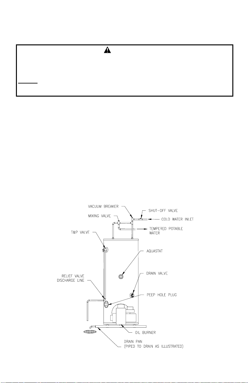
Please refer to the illustration below for the suggested piping arrangement.
Figure 2
8
Page 9

OIL TANKS AND PIPING
IMPORTANT!!
The instructions in this Section are general guidelines. The instructions for the
specific pump installed on the burner that you have purchased should take
precedence over the instructions given below. Read all of the instructions
provided with the burner before continuing with the installation.
A. Miscellaneous Information: If suction and return lines are less than
30 feet in length, 1/2" OD tubing may be used, but never smaller;
however, when the oil line is 30 feet or over, 5/8" OD tubing is
recommended. Where basement oil storage tanks or oil storage tanks
installed above the burner are used, and/or when the oil flows by
gravity to the oil pump, a single-stage fuel unit with a single oil line to
the pump may be used. Avoid as many connections as possible in the
suction line and make up all connections as tightly as possible, using
a good pipe joint compound for oil on all pipe threads. To minimize
the possibility of air leaks, tighten packing gland on any valve installed
in the suction line. Also, be sure to tighten the cover on the oil filter, as
filter gaskets often shrink. Check for kinks in the oil lines as well as for
possible air pockets and for loose connections. Underwriters'
Laboratories requirements now in effect stipulate a bottom outlet on
all 275 gallon oil storage tanks. This is to prevent the accumulation of
condensation, which causes the tank to rust. A water trap can be
installed at the oil storage tank outlet to prevent the water from
entering the burner. There are a number of additives on the market
that can be added to the oil storage tank with the fuel oil. These
additives hold the water in suspension and allow it to pass through the
burner. Consult a local fuel oil dealer for information concerning the
use of these additives.
B. Single Line System: NOT RECOMMENDED WHEN IT IS NECES-
SARY TO LIFT THE OIL. This type of installation is used where the
oil storage tank is above the burner and gravity oil feed to the burner
is permitted. The oil outlet and the line should be taken from the
bottom of the tank. This line should have a gradual slope downward of
approximately 112" per linear foot or more to a point directly below
where it is connected to the burner. A shut-off valve should be
installed in the line.
C. Two Line System: If oil storage is buried or if a suction line is long, it
is recommended that a two-stage fuel unit with a two line (suction and
return) installation be installed. For Suntec (Sunstrand) fuel units,
insert the bypass plug through the return port and turn tight. For
Webster pumps, bypass plug comes installed.
9
Page 10

Oil tanks and Piping Continued-
D. Suction Line: It is recommended that extra heavy wall copper tubing be
used for this line. If standard wrought iron pipe is used. It should be
scale free and not smaller than 5/8" OD. Copper tubing should be
installed to connect the pipe to the fuel unit. Where tubing is used, one
complete loop should be made in the tubing to connect the pipe to the
fuel unit. Where tubing is used, one complete loop should be made in
the tubing immediately below the fitting connecting it to the oil pump in
order to reduce transmission of noise and to prevent strain on the
burner. When the top of the oil storage tank is below the level of the fuel
unit, high points or air pockets in the suction line must be avoided
between the oil storage tank and the fuel unit, and a 5/8" OD ball check
valve should be installed to prevent the return of the oil to the oil storage
tank during the off cycle period of the burner. Do not run suction or
return line overhead as this greatly increases the possibility of air
pockets, oil leaks, siphoning and transmission of noise. When the top of
the oil storage tank is above the fuel unit and gravity feed to the unit is
not permitted, the suction line should be run to a point above the tank
where an approved anti-siphon valve and a 5/8" OD gate valve shall be
installed. These valves shall be installed inside. No ball check valve is
required, but a union should be installed between the gate valve and the
strainer to facilitate the removal of the strainer for cleaning when
necessary.
E. Return Line: The return line should be the same size as a suction line
and run as directly as possible from the return opening in the
fuel unit to the oil storage tank and should extend into the oil storage
tank to the same depth as the suction line.
F. Pressure Test for Buried Oil Lines: It is important that buried oil lines
be thoroughly tested for leaks before being covered.
CAUTION
DO NOT USE GASOLINE, CRANKCASE DRAININGS,
OR ANY OIL CONTAINING GASOLINE
OPERATION
Filling the Water Heater
1. Close the water heater drain valve by turning the handle clockwise.
2. Open the cold water shut-off valve.
3. Open several hot water faucets to allow air to escape from the system.
4. When a steady stream of water flows at the hot water faucets, the water
heater is filled. Close the faucets and check for water leaks at the
temperature-pressure relief valve and the hot and cold water
connections.
10
Page 11
BURNER AND THERMOSTAT INFORMATION
It is recommended that this water heater be installed with the following
burners and thermostat:
MODEL SIZE BURNER NOZZLE THERMOSTAT
30S Beckett AF Burner
(BW307)
32L Beckett AF Burner
(BW301)
50L Beckett AF Burner
(BW302)
70L Beckett AF Burner
(BW305)
.60 GPH 70° A Honeywell Aquastat 4103a1100 (160° Max.)
.65 GPH 80° B Honeywell Aquastat 4103a1100 (160° Max.)
.75 GPH 80° B Honeywell Aquastat 4103a1100 (160° Max.)
1.0 GPH 80° B Honeywell Aquastat 4103a1100 (160° Max.)
The correct burners and thermostat may be purchased from the same
supplier that provided the water heater to you.
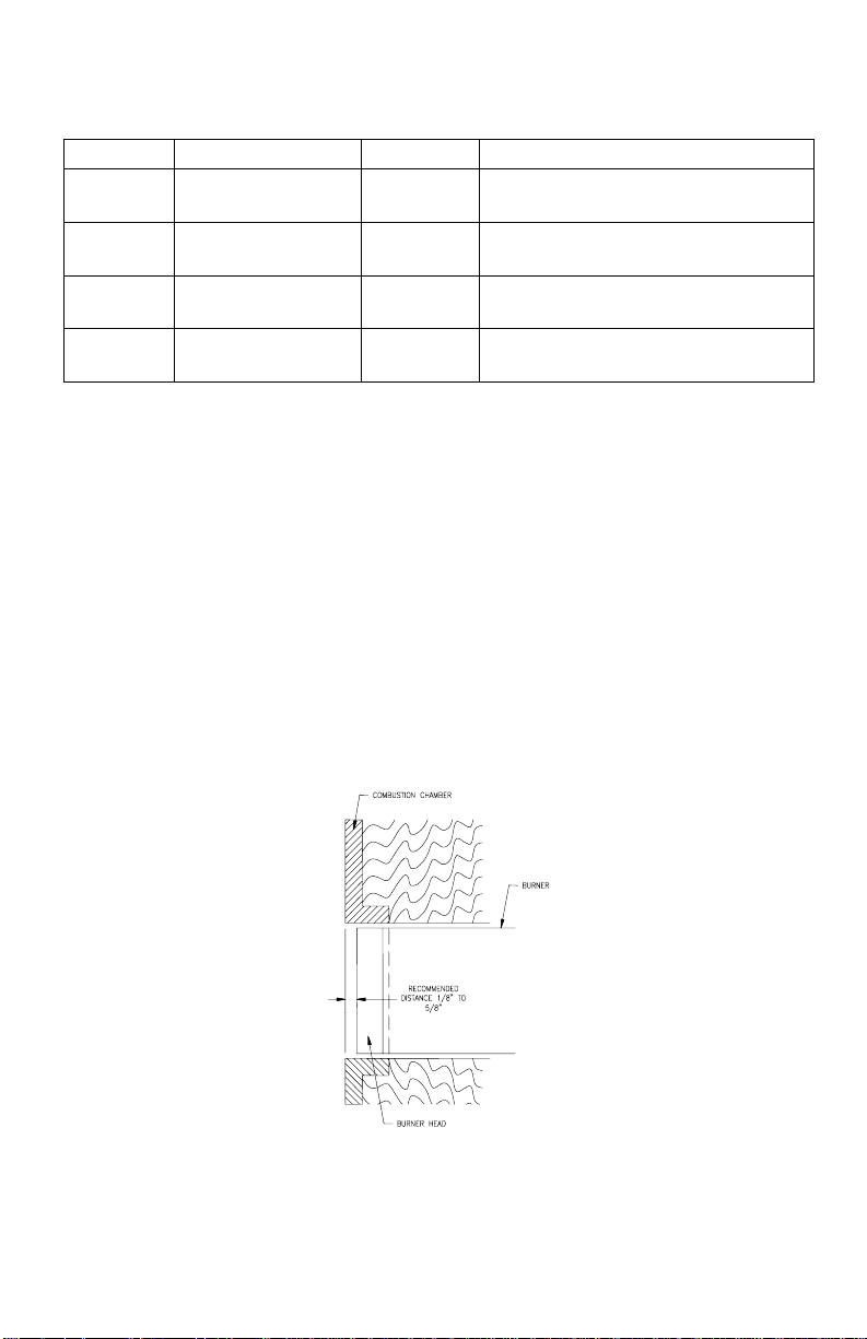
Installing the Burner: It is recommended that the burner be installed so that
the face of the burner head is between 1/8 of an inch to 5/8 of an inch from
the inside wall of the combustion chamber (see Figure 3). The position of the
burner head can be checked by putting your hand through the peep site hole
and feeling the location of the burner head. If the peep site hole is too small
for you to fit your hand through, then you can check the burner position with a
mirror. The burner head SHALL NOT extend inside the combustion chamber.
The burner is secured to the water heater by three 5/16” nuts.
CAUTION: Do not operate the burner if it is wet. If the burner gets wet, have
a qualified technician examine the burner before putting it back into operation.
Figure 3
Installing the Thermostat: The water heater comes with the thermostat well
installed in the tank. A Honeywell Aquastat 4103A1100 needs to be installed
in the thermostat well.
11
Page 12
T’stat information continued-
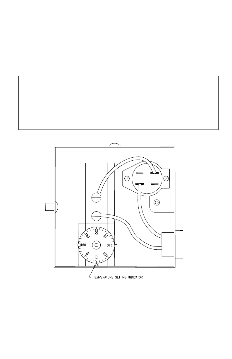
Adjusting the Thermostat: When adjusting the thermostat it should be
remembered that lower temperature settings are more energy efficient. To
adjust the thermostat, turn the dial clockwise to decrease the temperature and
counter-clockwise to increase the temperature. It is suggested that the
starting setting not exceed 120°F on the thermostat dial as indicated in (Figure
4).
CAUTION
Hotter water increases the risk of scald injury. Scalding may occur within
five (5) seconds at a temperature setting of 140°F. To protect against hot
water scald injury, install and anti-scald tempering valve in the water
system. This valve will reduce point of discharge temperature by mixing
cold and hot water in branch water lines. A qualified plumber should be
consulted.
Figure 4 – Thermostat with cover removed
WARNING
Escaping flue gases can be lethal. Make sure that the flue and venting
system is checked at least once a year by a plumbing professional or the
oil supplier's service technicians.
12
Page 13

T’stat information continued-
Motor Lubrication: Oil motor with one or two drops of non-detergent motor
oil.
Priming The Fuel Units: Locate the air bleed valve on the fuel unit (pump).
Place a container underneath the air bleed valve. Open the air bleed valve by
turning it one quarter of a turn in the counter-clockwise direction. Turn the
thermostat on the water heater to a setting that is high enough to allow the
burner to operate. Turn on the power supply to the burner. After the air is
pumped out of the fuel unit, let at least one pint of oil flow into the container.
While running under these conditions, the pressure valve in the pump will not
open; hence, there will be no flame. When a pint of oil has flowed into the
container, close the air bleed valve. The burner should start burning when the
air bleed valve is closed.
The above is not necessary when a two-pipe system is used. Install the
pressure gauge and turn burner on. The system will vent itself through the
return line and flame will appear as soon as the air has been eliminated. In the
event a lot of air is present and flame is not sighted within 45 seconds,
the cad cell will cause the relay to cut off for protection. It may then be
necessary to push the reset button on the burner on the burner module.
WARNING
DO NOT ATTEMPT TO START THE BURNER WHEN
EXCESS OIL HAS ACCUMULATED, WHEN THE UNIT IS FULL
OF VAPOR, OR WHEN THE COMBUSTON CHAMBER IS HOT.
TUNE-UP PROCEDURE
A. To Put The Burner in Operation: Remove the temporary oil
connection previously used and install a pressure gauge. Set all the
controls to the normal starting position. Close the main cut out
switch. The burner should start, ignite and burn. After you have
obtained a flame, the oil pressure should be checked and adjusted to
a pressure of 100 psi. This is the normal operating pressure. The air
inlet can then be adjusted so that the flame is a clean yellow with
slightly smoky tips. The burner flame can be observed through the
peep site hole. It may be necessary to readjust the air inlet after the
burner is running twenty minutes or more in order to obtain the
proper fire with a hot combustion chamber. After final adjustment,
tighten lock screws on air inlet, let unit cool and restart burner to be
sure burner operates on a cold start. Remove the pressure gauge
and install pipe plug.
13
Page 14

T’stat information continued-
B. Using Instruments To Set Fire: It is strongly suggested that the
installer use combustion test instruments when adjusting a flame. We
suggest 9 1/2% to 11% CO2 with a smoke reading no darker than 1
on the Bachrach Scale. Adjust the air inlet on the burner for the
minimum amount of air for clean combustion while the combustion
chamber is hot. Adjust the draft regulator so that there is -.01" to .04" draft over the fire, maximum. Take readings and adjust air so
that a minimum of 9 1/2% CO2 is obtained with a smoke reading
between 0 and 1. When using instruments in setting a fire, do not
lean towards getting a greater percentage of CO2 than a clean fire
will give. It is more important to keep the inside of the combustion
system clean than to receive a higher CO2.
C. Nozzle (Oil Input) Variations: Oil service personnel will carry
several nozzles of different manufacture, angles and types of spray
in order to obtain the most suitable for the particular application. Fuel
oils vary greatly. Because of this, nozzles will not always deliver the
gallons per hour or angle of spray that is indicated on the nozzle. In
addition, it has been found that, in certain areas, due to local
conditions, nozzles other than those furnished as original equipment,
give better performance due to the type of oil being delivered.
D. Draft: Draft reading in the stack should be -.02" to -.05". High Draft
may be caused by over firing or too much excess air.
If there is back draft caused by down draft, DO NOT operate the burner until
this situation is corrected. Back pressure (back draft or down draft) may also
be caused by the chimney termination being lower in elevation than
surrounding objects, such as buildings, hills, trees, rooftops, etc. Back
pressure may also be caused by an exhaust fan in the building.
IMPORTANT REMINDERS
1. Install all electrical work in strict accordance with local codes and
ordinances.
2. All unions must be of the ground seat type.
3. A check valve shall be installed in the suction line when the oil storage tank
is below the burner to prevent the return of the oil to the oil storage tank
when the fuel unit is not in operation.
4. Lubricate oil burner motor.
5. Set the draft to a range of -.02" to -.05".
6. See that the smoke pipe enters into the chimney far enough to be tight and
not so far as to reduce flue area. Its end should be flush with the inside of
the chimney.
7. Be sure that there is at least -.01" draft over the fire.
8. Be sure that there is no backpressure such as down draft or back draft.
9. Be sure that there is sufficient air in heater room for proper combustion at
all times.
10. Explain the operation of the burner to the owner -show where to oil -how
to operate controls and main cutout switch.
11. Hang burner-operating instructions as supplied with burner in prominent
place near installation.
14
Page 15

DRAINING THE WATER HEATER
Should it become necessary to completely drain the water heater, make sure
you follow the steps below:
1. Shut off the oil supply to the water heater.
2. Turn off/disconnect all electric power to the water heater.
3. Close the cold water supply shut-off valve.
4. Open a hot water faucet to allow air to enter the system.
5. Open the drain valve. This is threaded to receive a standard hose coupling.
Caution: This water may be hot.
To put the water heater back into operation, refer to "Filling The Water
Heater".
CAUTION:
Hydrogen gas can be produced in a hot water system served by this water
heater that has not been used for a long period of time (generally two weeks
or more). Hydrogen gas is extremely flammable. To reduce the risk of injury
under these conditions, it is recommended that the hot water faucet be
opened for several minutes at a convenient sink before using any electrical
appliance connected to the hot water system. If hydrogen is present, there
will probably be an unusual sound such as air escaping through the pipe as
the water begins to flow. There shall be no smoking or open flame near the
faucet at the time it is open.
MAINTENANCE
In addition, the following steps should be performed at six-month intervals
unless otherwise specified:
1. Make sure you clear the combustion air openings of any dust, lint or other
restrictions. Flow of combustion air MUST NOT be restricted.
2. Check the burner flame periodically. If it becomes out of shape or smoky,
call your service technician.
3. When cleaning your heater room or utility room, always turn off the burner
to reduce the amount of dust and lint drawn into the burner.
4. The electric ignition system and all controls should be checked periodically
for reliability of operation and adjusted if necessary.
5. Lightly oil the burner motor with "Medium" detergent-free automobile engine
oil twice per year.
6. Clean Strainer or Filter as follows:
a) Oil valves between oil storage tank and burner should be shut.
b) Remove Strainer cover.
c) Remove Strainer baskets and wash in kerosene.
d) Reassemble.
7. Drain off at least one gallon of water each month to remove the silt and
sediment from the water heater.
CAUTION: THIS WATER MAY BE HOT.
8. Check the temperature-pressure relief valve to insure that the valve has not
become inoperable. Lift the lever at the top of the valve several times until
the valve seats properly without leaking and operates freely. CAUTION:
THIS WATER MAY BE HOT.
15
Page 16
Maintenance Continued-
SAFETY WARNING
When lifting the lever of the temperature and pressure relief valve, hot
water will be released under pressure. Be certain that any released
water does not result in bodily injury or property damage.
If the temperature and pressure relief valve on the water heater discharges
periodically, this may be due to thermal expansion in a closed water supply
system. Please contact your water supplier or plumbing professional on how
to correct this situation. Do not plug the temperature and pressure relief valve.
Either a plug type, combination anode/nipple or both have been installed in
this water heater to extend tank life. The anode(s) should be inspected
periodically (every 2 years) and replaced if necessary. Contact the installing
professional plumber or the manufacturer listed on the rating plate for
replacement anode information. The use of a water softener may increase
the speed of anode consumption. More frequent inspection of the anode is
needed when using softened (or phosphate treated) water. You should
contact your supplier or a plumbing professional for replacement parts. Make
sure that you give the Part name, model number
water heater when ordering the parts.
and serial number of the
Contact your supplier or plumbing professional for replacement parts or
contact the company at the address given on the rating plate of the water
heater.
Provide the part name, model and serial numbers of the water heater when
ordering parts.
READ THE WARRANTY FOR A FULL EXPLANATION OF THE LENGTH
OF TIME THAT PARTS AND THE WATER HEATER ARE WARRANTED.
Manufactured under one or more of the following U.S. Patents:
RE.34,534; B1 5,341,770; 4,416,222; 4,628,184; 4,669,448; 4,672,919; 4,808,356;
4,829,983; 4,861,968; 4,904,428; 5,000,893; 5,023,031; 5,052,346; 5,081,696;
5,092,519; 5,115,767; 5,199,385; 5,277,171; 5,372,185; 5,485,879; 5,574,822;
5,596,952; 5,660,165; 5,682,666; 5,761,379; 5,943,984; 5,954,492; 5,988,117;
6,142,216; 6,684,821. Other U.S. and Foreign patent applications pending.
Current Canadian Patents: 1,272,914; 1,280,043; 1,289,832; 2,045,862;
2,092,105; 2,107,012; 2,108,186; 2,112,515.
Complete the following information and retain for future reference:
Model No: _______________________
Serial No:________________________
Installation Date: __________________
Service Phone No._________________
Days: ___________Nights: __________
Address:_________________________
Supplier:_________________________
Supplier’s Phone No:_______________
16
 Loading...