

Page 1
Installation, Operation and Maintenance Instructions Document 1105
Installation, Operation and
Maintenance Instructions for
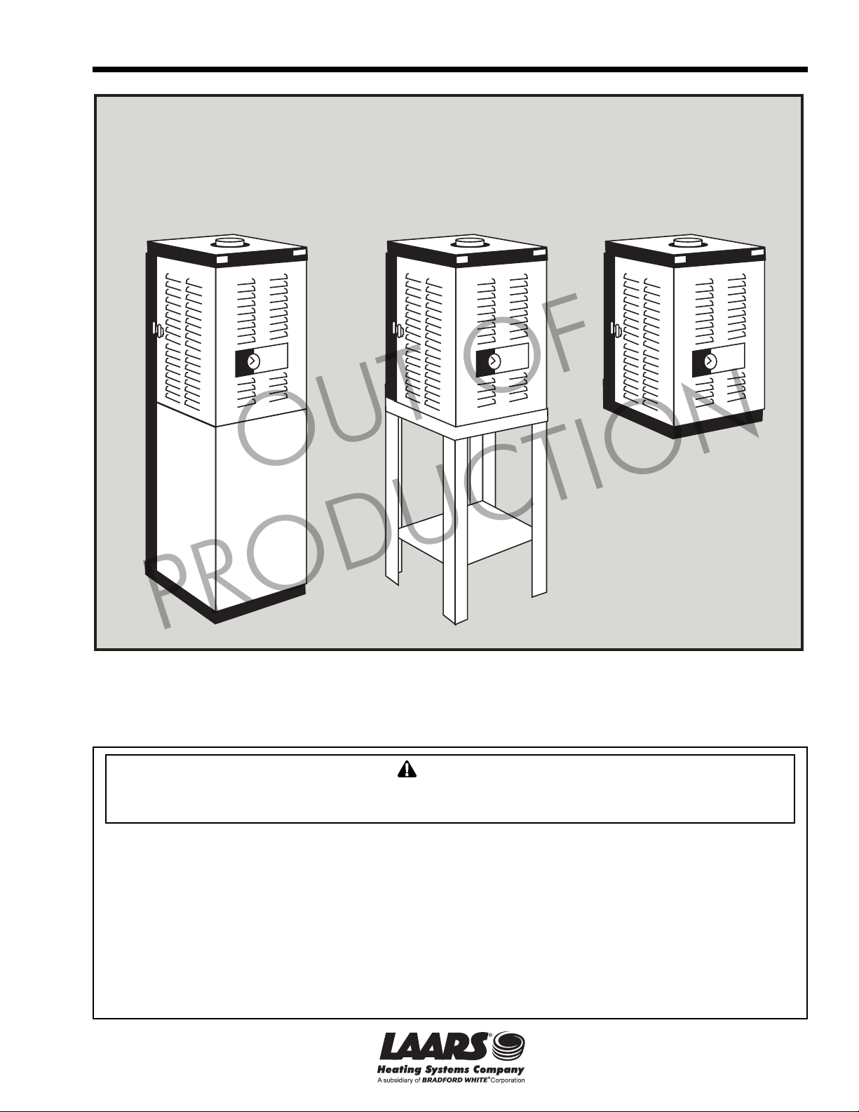
HW-M2 Series H-M2 Series HP-M2 Series
H Series
OUT OF
PRODUCTION
FOR YOUR SAFETY: This product must be installed and serviced by a professional service technician,
qualified in hot water heater installation and maintenance. Improper installation and/or operation could
create carbon monoxide gas in flue gases which could cause serious injury, property damage, or death.
Improper installation and/or operation will void the warranty.
WARNING
If the information in this manual is not followed exactly, a fire or explosion may result causing
property damage, personal injury or loss of life.
Do not store or use gasoline or other flammable vapors and liquids in the vicinity of this or
any other appliance.
WHAT TO DO IF YOU SMELL GAS
• Do not try to light any appliance.
• Do not touch any electrical switch; do not use any phone in your building.
• Immediately call your gas supplier from a nearby phone. Follow the gas supplier's
instructions.
• If you cannot reach your gas supplier, call the fire department.
Installation and service must be performed by a qualified installer, service agency, or gas
supplier.
Page 2

Page 2
LAARS Heating Systems
TABLE OF CONTENTS
SECTION 1.
General Information
1A. HW Series, H Series, HP Series .................. 4
1B. to the Installer: Before You Begin ................. 4
1C. Codes and Standards................................... 5
1D. Unpacking the H Series................................ 5
1E. Locating the H Series ................................... 5
1F. Clearances ................................................... 5
SECTION 2.
Venting Options
2A. Locating Unit With Respect to Ventilation .... 5
2B. Chimney Venting (USA Only) ....................... 6
2C. Installation .................................................... 6
2D. Alternate Venting Method (Canada Only)..... 6
2E. Installing Stainless Steel
Horizontal / Vertical Venting ......................... 8
2F. Connecting special Gas Vent to H Series .... 8
2G. Appliance Joint Procedure
Part #2400-350 ............................................. 8
2H. Appliance Joint Procedure
Part #2400-352 or Z-Vent
#02SVEPXX030 ........................................... 8
2I. Securing Special Gas Vent .......................... 8
SECTION 3.
Venting and Air Source
3A. The Direct Vent Kits
(part numbers 2400-326 or 2400-328) ....... 10
3B. Installing Direct Vent Kits ............................ 10
3C. Locating the Vent on an Outside Wall ........ 10
3D. Air Source For Combustion
(when not direct vented) ............................. 10
SECTION 4.
Gas Connection to H Series
4A. Gas Connection to H Series ....................... 11
4B. Domestic Water Piping ............................... 12
PRODUCTION
OUT OF
SECTION 5.
Hydronic Heat Piping
5A. Hydronic Heat Piping .................................. 12
5B. Feed Water Make-Up ................................. 12
5C. Hydronic Piping - HW Series ...................... 13
5D. Using In a Combined Hot Water
Heating and Chilled Water Cooling
System ....................................................... 13
SECTION 6.
Electrical Connections
6A. Electrical Connections ................................ 16
SECTION 7.
HP Mounting Piping
7A. Wall Mounting Instructions
Paloma/Hytech Replacement ..................... 17
7B. New Wall Mount Installation ....................... 17
7C. Hydronic Systems Connections ................. 17
7D. Plumbing Accessories Installation .............. 17
7E. Gas Supply Connection .............................. 17
SECTION 8.
HP Venting and Electrical
8A. Venting the HP-M2-Series .......................... 17
8A-1. AGA ............................................................ 17
8A-2. CGA............................................................ 18
8B. Electrical Connections ................................ 18
8C. Manufactured Home (Mobile Home)
Appliance Installation Instructions .............. 18
8C-1. Appliance Mounting .................................... 18
SECTION 9.
Check, Test and Start Up
9A. Filling System ............................................. 19
9B. Firing Burner ............................................... 19
9C. Check Limit Control Operation ................... 19
9C-1. Operating and Low Limit Control HW-M2 ... 19
9C-2. Operating Control H-M2 ............................. 20
9C-3. Safety Limit Operation H(W)-M2 ................ 20
9C-4. Stack Switch Operation H(W)-M2............... 20
9D. Common Vent Test .................................... 20
9E. Lighting and Shutdown Instructions ........... 20
Page 3

H Series
Page 3
SECTION 10.
Maintenance
10A. Owner Care and Maintenance ................... 20
10B. Service Maintenance .................................. 21
SECTION 11.
Burner Input and Boiler
Component Descriptions
11A. Adjusting Burner/Input ................................ 21
11A-1. Measuring CO2* .......................................... 21
11A-2. Measuring O2.............................................. 21
11B. Cleaning Combustion Chamber Coil .......... 21
11C. Unit Pump................................................... 22
11D. Gas Valve................................................... 22
11E. Safety Limit Switch ..................................... 22
11F. Operating Control ....................................... 22
11G. Igniter ......................................................... 22
11H. Pressure Differential Switch ....................... 22
11I. Transformer................................................ 23
11J. Low Limit (HW-M2 Series Only) ................. 23
11K. Blower ........................................................ 23
11L. Priority Relay - R1 (HW-M2 series only)..... 23
11M. Boiler Control.............................................. 23
11N. Stack Switch ............................................... 23
11O. Transfer Tank and Domestic Hot
Water Coil (HW-M2 series only) ................. 23
11P. Thermostatic Union
(H(P)-M2-Series Only) ................................ 23
11Q. Time Delay Relay (TDR)
11R. DHW Coil Replacement ............................. 24
11S. Tank Replacement ..................................... 24
PRODUCTION
(H(P)-M2-series only) ................................. 24
OUT OF
SECTION 12.
Symptom Evaluations
12A. Delayed Ignition .......................................... 24
12B. Noisy Operation .......................................... 25
12C. Insufficient Hot Water
(HW - M2 - series only) .............................. 25
12D. High Gas Consumption
(see also Cross Contamination) ................. 26
12E. Shortcycling
(H-M2, HP-M2 Series only) ........................ 26
12F. Cross Contamination and
Combustion Related Short Cycling
(units installed with Quick Vent) ................. 26
12G. Lock Outs
Integrated Boiler Control Lock Outs ........... 27
SECTION 13.
Sequence of Operation
................................................................... 27
SECTION 14.
Replacement Parts
................................................................... 37
SECTION 15.
Trouble Shooting
15A. S9301A Control Module ............................. 41
15B. Quick Reference Trouble Shooter .............. 42
HW-M2 Series H-M2 Series HP-M2 Series
HW-M2-130 H-M2-130* HP-M2-130*
HW-M2-100 H-M2-100 HP-M2-100
HW-M2-60 H-M2-60 HP-M2-60
Integrated Hydronic Heating Hydronic Heating Only Hydronic Heating Only
and Domestic Hot Water Appliance for Natural or Propane Gas. for Natural or Propane Gas
for Natural or Propane Gas. (Wall Hung).
* Field conversion only.
Page 4
Page 4
LAARS Heating Systems
SECTION 1
General Information
1A. HW Series, H Series, HP Series
The H Series boiler is a low pressure, hot water
boiler that is available in two (2) design
configurations. The HW series provides domestic hot
water as well as hydronic space heating. It includes an
insulated storage tank through which boiler water is
circulated. A heat exchanger within the tank transfers
heat from the boiler to the domestic hot water. The H
and HP series boilers are designed to provide hot
water for space heating, and can be plumbed to an
indirect water heater to supply domestic hot water.
By replacing the air and the gas orifices, the
basic H Series boiler has the flexibility to operate on
either natural or LP gas and may be fired at 60,000,
100,000 or 130,000 BTU/HR input. The H Series can
be direct vented by utilizing an optional concentric
vent system that will provide outside air for
combustion. H(W)(P)-60,100 & 130 appliances may
also be vented with 3" or 4" diameter stainless steel
horizontal / vertical venting as described on page 6.
The maximum length shall not exceed 50 equivalent
feet of 3" diameter or 100 equivalent feet of 4"
diameter. H(W)(P)-M2-130 appliances may also be
connected to a lined internal chimney.
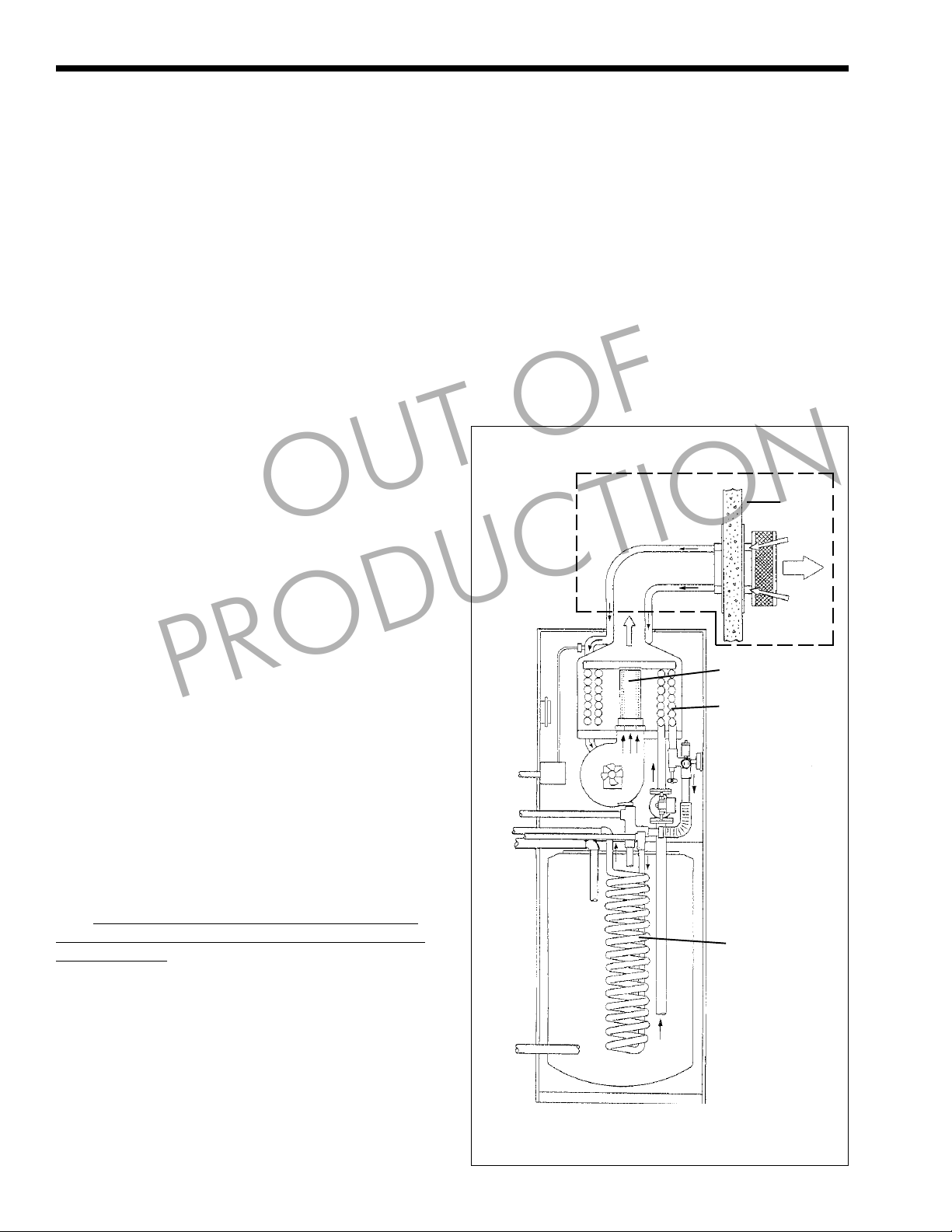
The H Series features a forced draft, pre-mixed
combustion system. All air for combustion is supplied
with the gas to the burner (flameholder). Both the
intake air and the gas are metered through separate
orifices before entering the combustion air blower.
The blower forces the air/fuel mixture through the
flameholder and into the combustion chamber. The
mixture is ignited from the hot surface igniter and
burns. Hot gases are forced out between the passes of
the heat exchanger into the flue collector. Flue gases
are discharged into the outside atmosphere through the
vent terminal, a chimney, horizontal or vertical
alternate vent.
Model H(W)-M2-60 & H(W)-M2-100 UNITS
MUST NOT BE CHIMNEY CONNECTED.
Installations with water containing 10 grains of
hardness or higher, must be installed with appropriate
water treatment.
PRODUCTION
OUT OF
1. Gas Burner*
2. Sealed Combustion* w/ P/N 2400-236 or
2400-238
3. Outside Vent Wall*
4. Outside Air For Combustion*
5. Copper Coil Heat Exchanger*
6. Thermostatic Union (H-M2)
7. Domestic Hot Water Coil (HW(D)-M2)*
8. Heating System Water Outlet
9. Heating System Water Return
10. Gas Supply
(*see Figure 1)
d
c
g
Î
l
Í
j
i
e
f
1B. To the Installer: Before You Begin
The H Series is uniquely different from any
heating boiler you have installed in the past. It is
important for you to take a few minutes to review the
contents of the Installation and Operating section of
this manual before you begin installation. This will
avoid making mistakes and causing confusion when
installing and operating the unit.
Î
k
Figure 1. HW-M2.
Page 5
H Series
Page 5
1C. Codes and Standards
All installations must be made in accordance
with: 1). The National Fuel Gas Code, ANSI Z223.1 latest edition or 2). CAN/CGA - B149 “Installation
Codes for Gas Burning Appliances and Equipment” or
with the requirements of the local utility or other
authorities having jurisdiction. Such applicable
requirements take precedence over the general
instructions contained herein. All electrical wiring is
to be done in accordance with 1). The National
Electrical Code ANSI/NFPA70-latest edition or 2).
The CSA standard C22.1 “Canadian Electrical Code Part 1” and local codes.
All vent installations must be made in
accordance with: 1). Part 7, Venting of Equipment of
the National Fuel Gas Code, ANSI 223.1- latest
edition, or applicable provisions of the local building
codes or 2). CAN/CGA - B149
When required by the jurisdiction authority, the
installations must conform to the American Society of
Mechanical Engineers’ Safety Code for Controls and
Safety Devices for Automatically fired Boilers, No.
CSD-l.
1D. Unpacking the H Series
a. Remove all packing and tie down materials.
b. On HW models, remove three (3) shipping bolts
from underside of base.
c. Make immediate claims ( to carrier ) if unit is
damaged.
PRODUCTION
OUT OF
1E. Locating the H Series
The H Series design is certified by the AGA and
CGA for installation on combustible flooring, in
alcoves, basements, closets, or utility rooms. It must
not be installed on carpeting. IF INSTALLED IN A
FINISHED AREA, PROVISION SHOULD BE
MADE FOR DRAINAGE OF ANY ACCIDENTAL
SPILLAGE OR LEAKAGE.
The location for the unit should be chosen with
regard to venting dimensions, convenient access to
piping, ventilation of operating components and
accessibility for service and cleaning.
The boiler shall be installed so that the gas
ignition system components are protected from water
(dripping, spraying, rain, etc.) during appliance
operation or service (circulator replacement, control
replacement, etc.).
1F. Clearances
The following dimensions and criteria should be
followed when choosing the location for the unit:
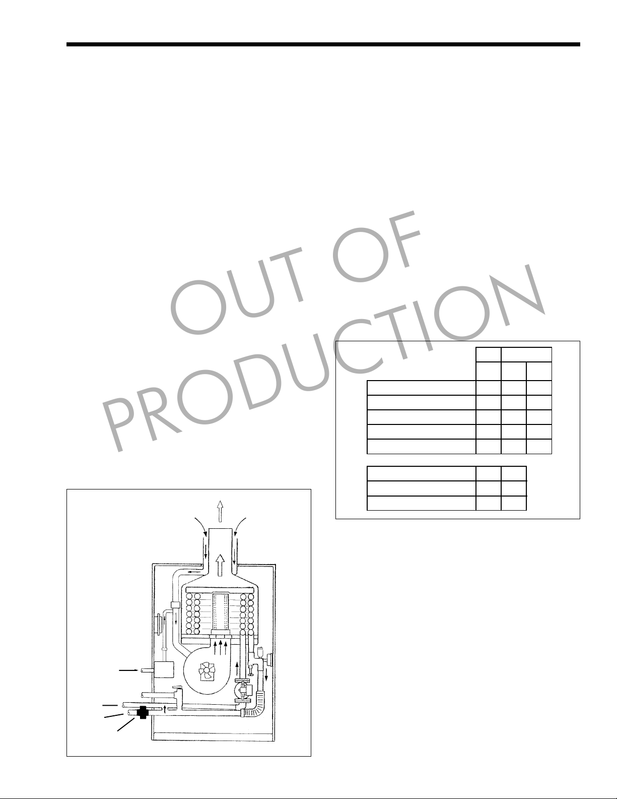
A. B.
AGA/
AGA CGA
CGA
Left Side 1" 6" 24"
Right Side (controls) 1" 12" 24"
Top 1" 14" 16"
Back 1" 9" 12"
Front 1" 24" 24"
l
k
j
h
Figure 2. H-M2.
Õ
Ö
Vent: Direct Vent 0" 0"
Chimney Connect 6" 6"
Alternate 3" 3"
Clearances
A. Minimum clearance from combustible
construction to meet AGA/CGA requirements.
B. Recommended clearance for accessibility and
venting.
SECTION 2.
Venting Options
2A. Locating Unit With Respect
to Ventilation
While the H Series, when direct vented, requires
no interior air for combustion, adequate airflow
around the unit and to the enclosed room must be
provided for proper cooling of electrical components.
Page 6
Page 6
SUPPLY
DOMESTIC
RETURN
LAARS Heating Systems
↑
3.5" deep
Figure 3. HW-M2.
2B. Chimney Venting (USA Only)
Model H(W)-M2-60 and H(W)-M2-100 MUST
NOT BE CHIMNEY OR B-VENT CONNECTED.
Model H(W)-M2-130 is a category l boiler and
may be vented in chimneys subject to the following
requirements:
Chimney must be internally lined or “B” vent
type. EXTERNAL OR UNLINED CHIMNEYS MAY
ONLY SERVE AS A CHASE for utilization of
stainless steel alternative venting providing no other
equipment is vented into it, or the chimney may have
an approved liner installed into the flue.
Two (2) or more vent connectors, from either
power or natural draft units, may enter a common gas
vent providing they conform to the requirements and
tables of the National Fuel Gas Code, ANSI Z223.1/
NFPA 54- latest edition, or applicable provision of the
local building code. None may be connected to
equipment with a positive vent pressure.
Locate unit as close to chimney as possible for
shortest vent connector.
2C. Installation
Determine height of chimney or B-Vent and
length of lateral run. Select vent connector diameter
from:
1). Table 1 or 2 of the National Fuel Gas Code,
ANSI Z223.1 / NFPA 54- latest edition (see
excerpts), or
2). Table G-3 of the Can /CGA - B149 Installation
Code.
Install an adaptor at the flue outlet of the unit to
step up to the diameter of the vent connector. Install
elbow for vent connector, if required. This elbow
should be full size of the vent connector. DO NOT
install a three (3) inch elbow between the flue outlet
PRODUCTION
OUT OF
Figure 4. H-M2.
on the unit and the adaptor. DO NOT use plastic vent
pipe in any part of the chimney vent connection.
Install vent connector between elbow, if used,
and chimney. Pitch vent connector up toward chimney
¼" per foot of lateral run. Secure all joints with
sheetmetal screws.
2D. Alternate Venting Method
(Canada Only)
The H Series may be vented vertically up
through a masonry chimney using a 4" diameter ULC
Certification Flexible Stainless Steel Vent.
Observe the following requirements:
1). The flexible vent must be run from the boiler up
through the entire chimney.
2). The chimney must terminate with a suitable vent
cap.
3). If chimney is exposed, the vent pipe should be
insulated.
4). The vent pipe must be installed with a ¼" per
foot upward slope from the boiler to the
chimney.
5). The vent pipe must be supported every 3' to
prevent sagging.
6). All joints in the vent must be secured with at
least two corrosion resistant screws and sealed
with an approved silicone sealant and checked
for gas tightness.
7). The vent system should be checked once a year
by a qualified serviceman.
Note: Boiler may not be vented in common with
another gas appliance or be vented using B-vent.
Page 7
H Series
Page 7
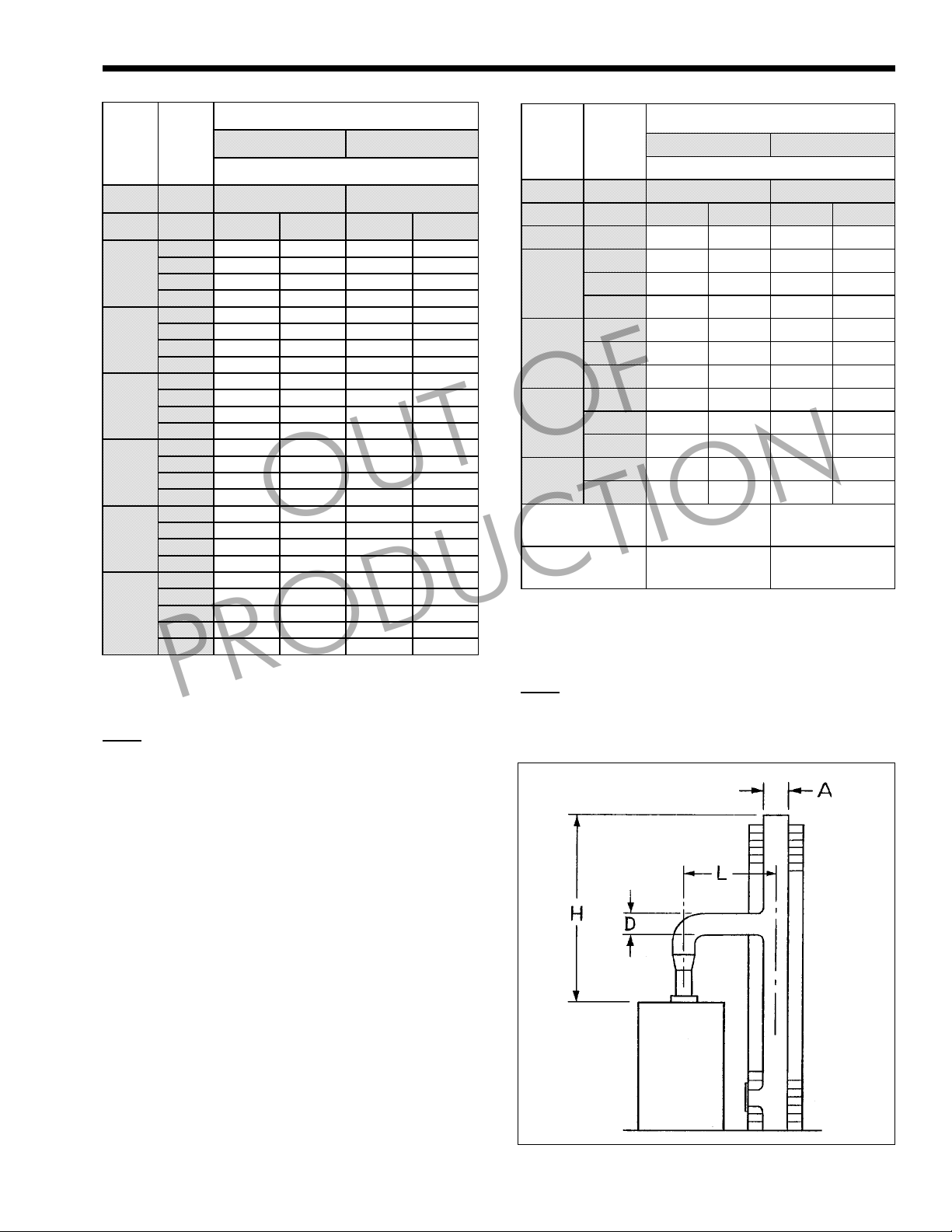
Vent Connector Diameter (A & D)
Height Lateral
H L Fan Assist Fan Assist
(ft) (ft) Min Max Min Max
0 85 249 126 373
6
8
10
15
20
30
Capacity of Tybe B Double-Wall with Single Wall
Metal Connectors Serving a Single Category I Appliance.
NOTE: TABLES APPLY TO MODEL H(W)-M2 130
(CATAGORY 1) APPLIANCES ONLY.
2 85 156 123 231
4 102 152
6 114 147
0 83 273 123 412
2 83 176 121 261
5 107 168
8 122 161
0 82 293 120 444
2 82 193 119 287
5 105 185
10
0 80 325 116 499
2 80 225 115 337
5 102 216
10 128 201
0 78 346 114 537
2 78 248 113 375
5 100 239
10 125 223
0 76 372 110 584
2 76 281 109 429
5 98 271
10 122 255
15
PRODUCTION
5" 6"
Appliance Rating in MBH
OUT OF
Table 1.
Type B Double Connector Diameter to be used with
chimney areas within the size limits at bottom
Height Lateral
H L Fan Assist Fan Assist
(ft) (ft) Min Max Min Max
10 2 68 519
2 53 475 64 613
15
20
30
50
Minimum Internal
Area of Chimney
Square Inches
Maximum Internal
Area of Chimney
Square Inches
Type-B Double Wall Flue Connector Serving a
NOTE: DERATE "FAN MAX" CAPACITY IN TABLE 2 BY
20% WHEN SIZING FLEXIBLE METAL FLUELINERS.
5 99 594
10 126 565
2 51 522 61 678
5 80 503 95 658
10 122 627
2 47 581 57 762
5 75 561 90 741
10 115 709
2 51 840
5 83 819
Capacity of Masonary Chimney Flue with
Single Category Appliance.
7" 8"
Appliance Rating in MBH
50 63
269 352
Table 2.
Figure 5. Tiled Lined Chimney. Masonry Chimney
Serving a Single Category I Appliance (see Table 2).
Page 8

Page 8
LAARS Heating Systems
2E. Installing Stainless Steel
Horizontal / Vertical Venting
(non concentric)
Stainless Steel Special Gas Vent listed to U.L.
Standard 1738 and U.L.C. Standard 636 may be used
to vent all H Series H(W)(P) and DH(P) models. Vent
pipe and fittings are manufactured to these Standards
by Heat-Fab, Inc. under the trade name of Saf-T
Vent® and by Z-Flex™ under the trade name of
Z-Vent. Follow the Special Gas Vent manufacturers’
instructions regarding design, location and assembly
of the vent system.
The H Series appliance may be vented with any
number of elbows or fittings provided that the
maximum equivalent feet of venting is not exceeded.
90° elbows in the vent system shall be considered to
be 10 equivalent feet. When vented with Special Gas
Vent, the H Series must not be common vented with
any other appliance.
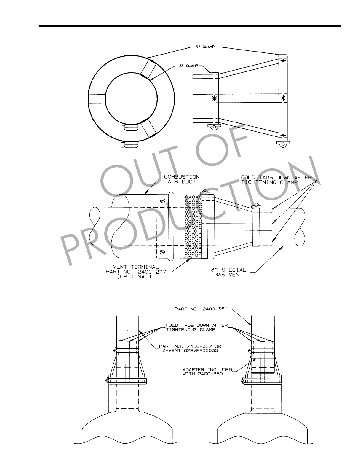
2F. Connecting Special Gas Vent
to H Series
Teledyne part number 2400-372 (Figure 6) is
used to secure the Special Gas Vent to the flue outlet
of the H Series*. Heat-Fab pipe or fittings (part
numbers 2400-350 or 2400-352) or the male end of
Z-Vent pipe (Z-Vent # 02 SVEPXX030) may be
installed over the flue outlet of the H Series.
*If a duct is used around the Special Gas Vent to
bring in combustion air from another location, the
connection of that duct to the appliance must be
secured with sheetmetal screws.
Each joint between the appliance and the last
joint before the location where the Special Gas vent
exits the duct must also be secured with sheetmetal
screws.
In this application, part number 2400-372 is not
used at the boiler flue collar. It is used, and must be
used, to secure the Special Gas Vent at the point
where the Special Gas Vent exits the duct.
The combustion air supply should be protected
from debris entering the duct. This may be done with a
H Series Vent Terminal, part number 2400-277, as
shown in Figure 7 or with a large mesh screen.
Follow the Special Gas Vent manufacturer’s
instructions for cleaning and sealing all parts before
assembling.
PRODUCTION
OUT OF
2G. Appliance Joint Procedure
Part #2400-350 (See Figure 8)
Apply 1/4" bead of silicone sealer (GE108 or
Novagard 400) to the 3 inch (3") flue outlet of the H
Series approximately one inch (1") from the end.
Slide flue adapter over the H Series flue outlet
(flared up end) and push down to stop (do not force
adapter beyond stop).
Apply another bead of silicone around this joint
and smooth out.
Apply 1/4" bead of silicone to the straight end of
the 2400-350 pipe approximately 1/4" from the end.
Slide the pipe into the adapter until it bottoms in
the adapter.
Apply another bead of silicone around this joint
and smooth out.
2H. Appliance Joint Procedure
Part #2400-352 or Z-Vent
#02SVEPXX030 (see Figure 8)
Apply 1/4" bead of Silicone sealer (GE 108 or
Novagard 400) to the 3 inch (3") flue outlet of the H
Series approximately one inch (1") from the end.
Slide pipe over the H Series flue outlet and push
down to stop (do not force pipe beyond stop).
Apply another bead of silicone around this joint
and smooth out.
2I. Securing Special Gas Vent
Attach part number 2400-372 to 5" collar on
appliance or end of five inch (5") combustion air duct
and tighten large clamp.
Form tabs on part number 2400-372 onto Special
Gas Vent pipe and secure tabs with the 3" clamp.
After the clamp has been tightened, fold the end
of the tabs down over the clamp.
DO NOT use screws in any portion of the 3"
Special Gas Vent.
For vertical venting see instructions in the
Vertical Vent Kit pertaining to use of raincaps and
condensate drip tee's.
Page 9
H Series
Figure 6. Part Number 2400-372.
Page 9
OUT OF
PRODUCTION
Figure 7. Vent Terminal Used As An Air Screen.
Figures 8 and 9. Vent Pipe Attachment.
Page 10
Page 10
LAARS Heating Systems
SECTION 3.
Venting and Air Source
3A. The Direct Vent Kits
(part numbers 2400-326 or 2400-328)
When using the Direct Vent Kit, the H Series is a
sealed combustion unit. All of its air is drawn in from
the outside through the 5" outer pipe. Flue gases are
vented through the 3" vent pipe positioned inside the
5" intake pipe. The hot flue gases are surrounded by
the intake flow of cooler outdoor air. This vent system
may be installed through, and be in contact with,
combustible materials.
3B. Installing Direct Vent Kits
The Direct Vent H Series is certified with a
maximum of 15 linear feet of vent pipe and one set of
elbows. Systems may be vented with a maximum of
three sets of concentric elbows providing the
maximum length is reduced by three linear feet for
each additional elbow set. Provide a minimum of 16"
above the top of the boiler for vent installation and
servicing. There are two vent kits available. Part
numbers 2400-326 and 2400-328 provides all of the
required materials. Part number 2400-326 for vent
installations which require adjustable height and
horizontal run. This kit will permit vertical and
horizontal lengths of pipe from 2' or 4'. One foot
extensions and 2' to 4' extensions are available to
increase vent lengths to the maximum allowed.
Additional sets of elbows are also available.
Part number 2400-328 provides all of the
required materials for vent installations which may
have a fixed height of 11 inches and an adjustable
horizontal run of 2' - 4'. Accessories for P/N 2400-326
also fit P/N 2400-328.
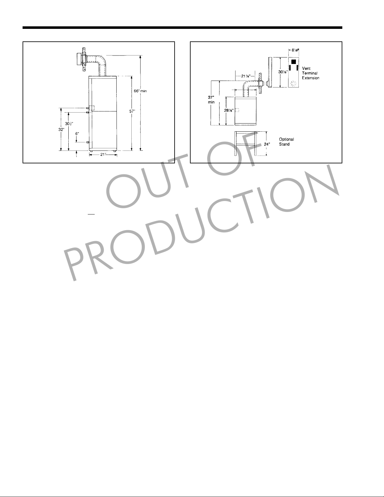
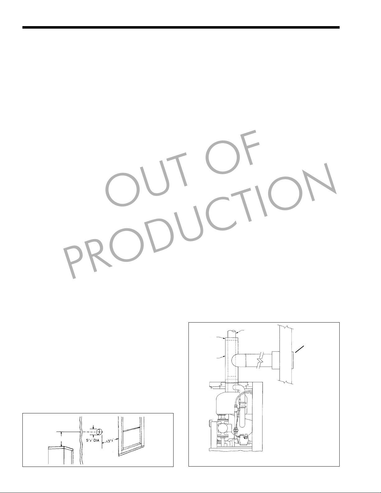
3C. Locating the Vent on an Outside Wall
Exterior vent should terminate 16½" above
grade, and at least 13 ½" from any other building
opening such as doors, windows, etc. Units
terminating below the top of the boiler must reduce
allowable vent length by 1" for every foot of vertical
drop below the top.
Vent opening should be well away from
shrubbery or other obstructions that would prevent
free air flow to and from vent terminal. Do not
PRODUCTION
OUT OF
terminate vent under decks, stairways, or car ports.
When ever possible, locations under windows should
be avoided.
NOTE: Should it be impossible to locate
opening center line 16 ½" above grade, use optional
Vent Terminal Extension (Part Number 2400-278).
(see Figure 4).
Vent terminals must also be at least 3' above any
forced air inlet located within 10', and at least 7' above
grade when located adjacent to a public walkway, and
cannot terminate in a location where condensate or
vapor may be a nuisance, hazard, or could be a
detriment to other equipment. Vent terminals must
have a minimum clearance of 4 feet horizontally from,
and in no case above or below electrical meters, gas
meters, regulators, and relief equipment unless a 4 foot
horizontal distance is maintained .
Do not locate the vent terminal where blockage
by snow is a possibility, or where flue products could
strike against building materials and cause degradation.
3D. Air Source For Combustion
(when not direct vented)
When using these venting methods the H Series
draws all combustion air through the top of the unit
and from the space around the boiler. When locating
the unit in unconfined spaces in buildings, infiltration
may be adequate to provide air for combustion and
ventilation; however, in buildings of unusually tight
construction, or when locating the unit in a confined
space, additional air should be provided and the
following guidelines must be followed.
1. If the space is in a building of unusually tight
construction, air should be obtained from
outdoors, or from spaces which freely connect
with outdoors.
PLUG
5" TEE
3" VENT
4" MIN. DIA
INTAKE AIR
SCREEN
8" MIN.
Figure 10. Direct Vent Terminal Clearance.
H, HP or HW with
Separate Air
Source.
ALTERNATE TO 1. - 3. ABOVE
Figure 11. H, HP or HW with Separate Air Source.
Page 11
H Series
2. For boilers in confined rooms, two permanent
openings shall be provided - one within 12" of
the ceiling, and one within 12" of the floor of
each room. Each opening shall be at least one
square inch per 1,000 BTU/HR boiler input, but
not be less than 100 square inches. These
openings shall freely connect with areas having
adequate infiltration from outside.
3. When all air is provided from outdoors, the
confined space shall be provided with two
openings as outlined above. These openings shall
connect directly, or by ducts, with outdoors or
spaces (crawl or attic) that freely connect with
the outdoors, and shall be of the size listed below
for that particular arrangement.
a. One square inch of free area per 4,000
BTU/HR of boiler input for direct outdoor
air supply through an outside wall, or
through vertical ducting directly to outside.
b. One square inch of free area per 2,000
BTU/HR of boiler input for direct outdoor
air through horizontal ducting.
c. All ducting shall be of the same size as the
opening to which it is connected.
OUT OF
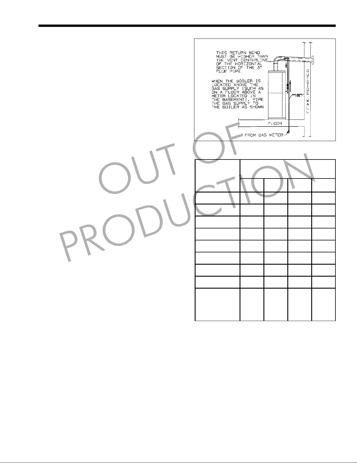
Figure 12. Gas Piping.
Length
of
Pipe
10' 132 278 520 1,050
20' 92 190 350 730
Capacity of Pipe in MBTU / HR
Page 11
(.6 Specific Gravity)
½" ¾" 1" 1¼"
SECTION 4.
Gas and Domestic Water Piping
4A. Gas Connection to H Series
least 4" W.C and no greater than 13" W.C. Check with
your local gas utility or supplier for availability of this
pressure range.
minimize pressure drop between meter or regulator
and unit.
applicable codes. IF UNIT IS INSTALLED ABOVE
GAS SUPPLY, RUN PIPPING UP TO A POINT
ABOVE VENT CENTER LINE AND BACK DOWN
TO UNIT. THIS WILL PREVENT WATER FROM
ENTERING GAS SUPPLY SHOULD A LEAK
DEVELOP IN THE BOILER SECTION (see
Figure 12).
accordance with state and local requirements.
to trap sediment and for test gauge access (see
Figure 12).
compound resistant to action of liquefied petroleum
gas whether LPG is used or not.
be disconnected from the gas supply piping system
PRODUCTION
The H Series requires an inlet gas pressure of at
Referring to Table 4, size supply piping to
Run gas supply line in accordance with all
Locate and install manual shutoff valves in
Install drip leg, ground joint union and drip cap
Support all piping with proper hangers.
All threaded joints should be coated with piping
The boiler and its individual shutoff valve must
30' 73 152 285 590
40' 63 130 245 500
50' 115 215 440
75' 93 175 360
100' 79 150 305
150' 64 120 250
Additional
length to be
added for each
tee or bend
during any pressure testing of that system at test
pressures in excess of 1/2 psig (3.5kPa).
The boiler must be isolated from the gas supply
piping system by closing its individual manual shutoff
valve during any pressure testing of the gas supply
piping system at test pressures equal to or less than
1/2 psig (3.5kPa).
The boiler and its gas connection must be leak
tested before placing the boiler in operation.
Purge all air from gas lines.
Note: H Series’ are certified for 4" to 13" W.C.
We find on L/P the unit performs better when the low
pressure regulator is not set over 9" W.C. Use an
appliance regulator (maxitrol RV48 or equivalent) if
more than 3" lock up occurs in gas supply.
1.3' 1.7' 2.2' 2.7'
Table 4. Gas Pipe Capacity.
Page 12
Page 12
WATER
H
E
A
T
M
A
K
E
R
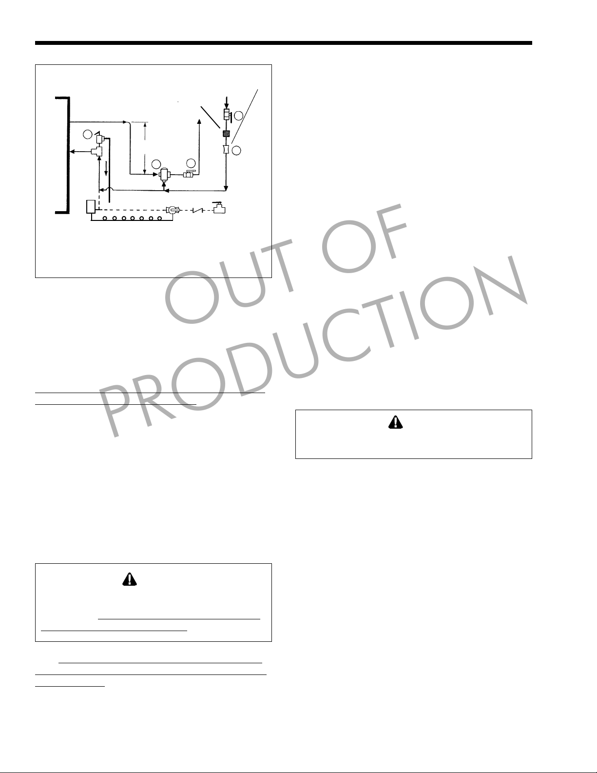
Figure 13. Domestic Water Piping.
1
6"*
15
AQUASTAT
OPTIONAL RETURN LINE PIPING
* or per valve manufacturers instructions.
CIRCULATOR
4B. Domestic Water Piping
Connect hot water tempering valve (12) “HOT”
port to hot water outlet from unit. This valve should be
mounted 3" to 6" below the outlet and set for 120° F
mixed delivery temperature or as local codes dictate.
H SERIES RECOMMENDS ANTI SCALD VALVE
SUCH AS SPARCO OR DANFOSS. (see Figure 13).
Connect gate or shutoff valve (13) to tempering
valve (12) “MIX” port, and cold water inlet.
Install supplied flow restrictor (14) ahead of mix
valve tee.
Connect pressure relief valve (1) (if required by
codes), maximum 150 PSI as close to the unit as
possible. No other valves or restrictions may be
installed between the H Series and the relief valve.
(DO NOT USE A TEMPERATURE/
PRESSURE RELIEF VALVE AS THIS IS NOT A
STORAGE HOT WATER HEATER).
*Model 60 is not recommended for larger hot
water demands.
Failure to install a hot water tempering valve (12)
creates a scalding hazard with potential for serious
bodily injury.
not designed as anti scold valves.
Installations with water containing 10 grains of
hardness or higher, must be installed with appropriate
water treatment.
PRODUCTION
WARNING
Some brands of tempering valves are
SOFTENER
12
OUT OF
SUPPLIED
13
14
13
LAARS Heating Systems
SECTION 5.
Hydronic Heat Piping
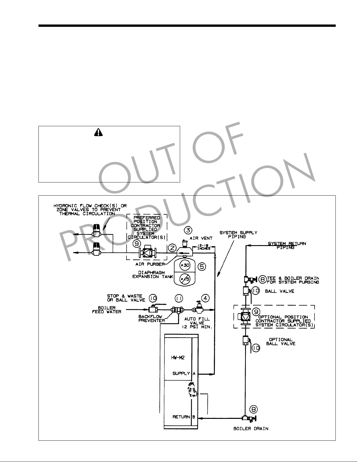
5A. Hydronic Heat Piping
Hydronic Connections, Fittings and Accessories
(see Figure 16).
NOTE: A SEPARATE HEATING
CIRCULATOR MUST BE PROVIDED IN
SYSTEM PIPING, FOR ALL MODELS.
Connect system supply to 1" supply connection (A).
1. Install thermostatic union (supplied) on H, HP
boilers.
2. Pipe the discharge of the relief valve, full size, to
a drain or in a manner to prevent injury or
property damage in the event of pressure relief.
3. Install an air purger (2) in supply line.
4. Install automatic float type air vent (3) on air
purger.
5. Connect diaphragm type expansion tank (5) to
air purger.
6. Install a boiler drain valve (8) adjacent to unit in
return line.
7. Connect system return to 1" return connection (B).
8. Install a properly sized circulator (9) with
optional isolation valves (10).
Caution
All hot water pipes must be installed with a
minimum 1" clearance from combustible materials.
NOTE: H, HP boilers installed in radiant (in
floor) systems and other low mass systems should be
provided with a buffer tank to assure constant supply
temperature without excessive boiler short cycling
(see Figure 17).
5B. Feed Water Make-Up
Connect boiler feed water supply with shut off
valve to inlet connection of automatic fill valve (4).
If codes require, install suitable back-flow
preventor (11) between automatic fill valve and city
main.
To ensure sufficient expansion volume of the
hydronic system water due to heat-up and cool-down
during normal operation, a #30 or larger expansion
tank must be used on all HW series applications.
Page 13
H Series
Page 13
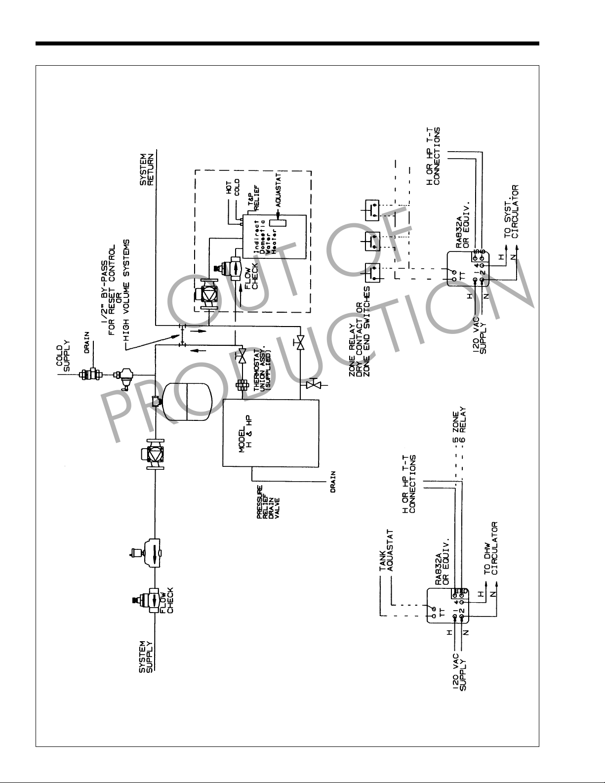
5C. Hydronic Piping - HW Series
HW-M2 boilers are installed in single and
multiple zone systems ( using either zone valves or
zone circulators) in the same manner as any other
residential boiler. Systems with zone circulators or
single zone systems require the installation of a
hydronic flow check (6) to prevent gravity circulation
of heating supply water when no heat is desired.
To minimize heat loss from the storage tank
(HW) during standby periods, it is recommended that
the piping between the H Series up to and including
the vertical leg be insulated with ½" - ¾" of insulation.
Caution
Unless equipped with optional stainless steel tank,
the HW model must not be direct connected to a
heating system utilizing oxygen permeable tubing,
(see warranty). Provide a water to water heat
exchanger between systems to prevent corrosion of
tank or other components.
OUT OF
Nontoxic heating system antifreeze may be
added to the hydronic system provided that the
concentration does not exceed 35% and the antifreeze
contains an anti-foamant.
5D. Using In a Combined Hot Water
Heating and Chilled Water Cooling
System
When the H Series is used in connection with a
refrigeration system, it must be installed so that the
chilled medium is piped in parallel with the boiler
with appropriate valves to prevent the chilled medium
from entering it.
The boiler piping system of a H Series boiler
connected to heating coils located in air handling units
where they may be exposed to refrigerated air
circulation must be equipped with flow control valves
or other automatic means to prevent gravity
circulation of the boiler water during the cooling
cycle.
PRODUCTION
Figure 14. Hydronic Piping (HW).
Page 14
Page 14
LAARS Heating Systems
OUT OF
PRODUCTION
Figure 15. Hydronic Piping with Indirect H(P).
Page 15

H Series
Page 15
OUT OF
Figure 16. Hydronic Piping H(P) Models.
PRODUCTION
Figure 17. Hydronic Piping H(P) in Radiant “in floor” or Low Mass Heating System.
Page 16

Page 16
LAARS Heating Systems
SECTION 6.
Electrical Connections
6A. Electrical Connections
All electrical wiring must conform to local codes
and/or the 1). National Electric Code or 2). Canadian
Electrical Code - Part 1.
The unit must be electrically grounded in
accordance with the requirements of the authority
having jurisdiction or, in the absence of such
requirement, with the 1). National Electrical Code.
ANSI/NFPA NO.70- latest edition, or the CSA
Standard C22.1 “Canadian Electrical Code - Part 1”.
Single pole switches, including those of safety
controls and protective devices must not be wired in a
grounded line.
All electrical connections are made in the field
wiring box which is located on the right side of the
unit.
OUT OF
PRODUCTION
Figure 18. Single Zone.
NOTE: All internal electric components have
been pre-wired. No attempt should be made to connect
electric wires to any other location except the wiring
box as described below.
1. Main power
Connect a 15 amp fused 120 volt supply to the
main power switch illustrated (hot leg is
connected directly to switch). Neutral leg to
white wire. Ground wire can be connected to the
grounding screw in the box or on the switch.
2. For single zone installations, connect room
thermostat (T-T) wires to the red and white/red
wires. Connect circulator (120 volt, 5 amps
maximum) between the blue wire and the white
wire (neutral) (see Figure 18). Set thermostat
anticipator to 0.9 amps.
3. Zone Valves and Thermostats: Fig 19 (Fig 20 for
3 wire zone valve such as TACO) or DC
magnatrol valves.
Install external 24 volt transformer of sufficient
V.A. to power combined load of zone valves.
Consult zone valve manufacturer’s instructions.
Connect circulator (120 volt, 5 amp maximum)
between the blue wire and the white wire (neutral).
4. Multi-Zone/ Multi-Relay-Circulator
Installations: Multiple circulators must not
exceed 5 amps when connected to blue wire.
Blue wire must be used on all HW series (see
Figure 21).
NOTE: On zone valve systems such as Taco,
Automag and others which do not have isolated (dry)
contact end switches, a single pole isolating relay must
be utilized. (see Figure 20).
LEGEND
S1 Disconnect Switch
TH1
24-Volt Thermostats
TH2 R2
TH3 R3
C1
Zone Circulators Max 5 AMP
C2 ZV2
120 VAC.
C3 ZV3
Figure 19. Zoning with Zone Valves.
Figure 20. Zoning with 3 Wire Zone Valves. Figure 21. Zoning with Circulators
R1
ZV1
Zone Relays.
Honeywell R845A or
equivalent.
Zone Valves.
Honeywell V8043 or
equivalent.
Page 17

H Series
Page 17
SECTION 7.
HP Mounting Piping
The Model HP-M2-Series may be used as either
a Paloma Pak/Hytech boiler replacement or as a new
wall-mount installation. Carefully unpack HP unit.
Read all installation instructions before starting the
installation. Remove the Front removable jacket and
find the plumbing accessories package inside the unit.
7A. Wall Mounting Instructions
Paloma/Hytech Replacement
Hang the HP-M2 as assembled from the
manufacturer onto the existing wall bracket. Do not
remove the brackets which are attached to the new
unit. If the existing wall bracket does not align with
the slotted mounting holes on the rear of the HP-M2,
remove the old bracket from the wall and follow
instructions for new wall mount below.
7B. New Wall Mount Installation
Remove the bolts, nuts and washers that secure
the two mounting brackets to the bottom and rear of
the HP-M2 cabinet. Remove the U-channel spacer
bracket from each wall bracket and discard. (Spacer
brackets are used only with original bracket in Paloma
Pak/Hytech retrofit installations)
Attach the included mounting template to the
selected wall location. Mark and drill holes for
appropriate mounting hardware at the template
specified locations. Remove template from the wall
and securely affix the two wall brackets to the wall
surface with appropriate mounting hardware (provided
by installer).
assemble the bolts, nuts and washers to affix the unit
onto the wall brackets.
U-CHANNEL SPACER BRACKETS WHEN
MOUNTING THE WALL BRACKETS DIRECTLY
TO A WALL.
7C. Hydronic Systems Connections
the necessary fittings to match the Paloma Pak supply
and return piping. If the original wall bracket is
compatible with the slotted mounting holes on the rear
of the HP-M2, the supply and return pipe unions
attach directly to the existing piping. If the installation
is new or if the old bracket is incompatible or
unusable, the return and supply connections will
require re-piping to match the HP-M2 connections.
7D. Plumbing Accessories Installation
1) Attach boiler drain plumbing accessory to the
PRODUCTION
Lift the HP-M2 onto the wall brackets and re-
NOTE: DO NOT REINSTALL THE
The H SERIES HP-M2 Series is supplied with
labeled “return” on the bottom of the HP-M2.
OUT OF
2) Separate Thermostatic Union Assembly halves
and thread the 1" nipple side to the labeled
“supply” on the bottom of the HP-M2. Attach the
remainder of the union assembly onto the top
half of the union. Be sure to use appropriate
thread sealers to assure leak-tight joints.
3) a. Where the HP-M2 is a direct replacement
for a PalomaPak/Hytech the installation is
completed by connecting union halves
together.
b. If the installation is new, refer to the piping
schematics and instructions on page 10 -12.
7E. Gas Supply Connection
If the installation is a direct retrofit, the gas
supply will require re-piping to connect to the HP-M2
gas inlet. If the gas is supplied from below the unit, be
sure to run supply pipe to a point higher than the vent
center line before connection to the unit gas valve.
On new installations refer to the gas piping
section for gas pipe sizing and related information.
SECTION 8.
HP Venting and Electrical
8A. Venting the HP-M2-Series
The HP-M2 may be vented using any of the
venting options available to the H(W)-M2-Series.
These options include Direct Vent, Outside Air
vented, Alternate horizontal/vertical venting (using
“Special Gas Vent”) or internal lined or “B” Vent type
chimneys.
MODEL HP-M2-60 & HP-M2-100 MUST
NOT BE CHIMNEY CONNECTED OR “B”
VENT CONNECTED.
8A-1. AGA
When used as a retrofit boiler vented into a
chimney or a “B” Vent, be sure to check current vent
and vent connector sizing tables. Only units fired at
130MBTU/hr may be vented with this option. Under
no circumstances shall the HP-M2-60 be chimney
connected or “B” vented using 3" vent or vent
connectors. The unit 3" vent collar must be increased
to a size which will accommodate the chimney system
for the appropriate BTU/hr input of the boiler.
In the event the unit firing rate and masonry
chimney parameters do not fall within the
recommendations in the latest N.F.G.C.* chimney
sizing tables, a flexible chimney liner may be utilized
in the chimney. Sizing capacity for metal chimney
liners may be obtained by 20% de-rating (or 80%) of
the “fan max” capacity from B vent tables. See page 5
for vent table excerpts.
*National Fuel Gas Code ANSI Z223.1 / NFPA 54.
Page 18

Page 18
LAARS Heating Systems
8A-2. CGA
Refer to page 4 for Alternate Venting Method.
8B. Electrical Connections
If the installation is new, wire the unit per the
applicable wiring diagram for line voltage (120VAC)
and control (24VAC) wiring connections.
Do not connect an external voltage source to the
HP 24 volt (T-T) wires. Install an isolation relay if
required per diagram Figure 20.
Where a HP-M2-Series in a Paloma Pak/Hytech
retrofit is connected to a single zone system, the
original transformer relay control-pak should be
removed and all field wiring connected to the unit
electrical connection junction box on the right side of
the unit. The 120VAC power input, 120VAC system
circulator output and thermostat should be wired as
outlined in figure 18.
Be sure to set the thermostat heat anticipator to
0.9 amp for single zone connection.
If a retrofit installation includes multiple zones,
any one of the options provided in this manual may be
OUT OF
used, or the existing transformer relay control-pak
may be utilized and re-wired according to the diagram
below. Where two wire or three wire zone valves are
used, this is the preferred wiring method on retrofits.
8C. Manufactured Home (Mobile Home)
Appliance Installation Instructions
These appliances are design certified to conform
to the requirements of ANS Z21.10.3 for installation
in manufactured homes (mobile homes) when installed
in conformance with this manual supplement and the
manual.
8C-1. APPLIANCE MOUNTING
Model HP Series appliances are provided with a
wall mounting bracket.
Model H Series appliances are provided with
mounting holes in the base. Either lag bolts or through
bolts must be used for secure attachment of the
appliance to the structure.
Model HW Series appliances are attached to the
structure by attaching angle brackets from the structure to the secured clearance brackets. See Figure 23.
PRODUCTION
Figure 22. Paloma Pak/Hytech Transformer Relay Control Pak Rewiring.
Figure 23. Mounting in Mobile Homes.
Page 19

H Series
Page 19
SECTION 9.
Check, Test and Start Up
9A. Filling System
1. Open all supply and return valves.
2. Fill heating system to minimum operating
pressure of 12 psig.
3. Open bleed pet cock and bleed air from boiler
coil until a good stream of water comes out.
(H(P)-M2 series), Item 8 on page 33.
4. Purge all lines by opening vents, or with flushing
valves.
5. Close gas valve.
6. Turn on 120 volt power, and listen for unit
circulator to start. Unit will cycle off on lockout.
7. Open all vents again to discharge any additional
air and close off after air is eliminated.
8. System is now ready for operation.
OUT OF
9B. Firing Burner
1. Be sure that system has been filled properly (see
above) and is leak tight.
2. Open gas cock (s). Open manual gas shutoff
valve by turning to “on” position.
3. Turn on main switch, and set thermostat to call
for heat. In approximately 2 seconds, blower will
come on.
PRODUCTION
NOTE: Burner may not ignite on first attempt
because of air in gas lines. In this case, blower will
stop after 5 minutes. Should this happen, turn off main
switch. Wait 5 minutes and turn on main switch again.
4. If burner fails to ignite after three attempts, refer
to Trouble Shooting Section 2, Service Manual
or call service for troubleshooting.
Caution
Should any pronounced odor of gas be detected, or
if the gas burner does not appear to be functioning
in a normal manner, close main shutoff valve, do
not shut off switch, and contact your heating
contractor, gas company, or factory representative.
5. You MUST check flame monitoring control
(ignition system safety shutoff device).
a. Close gas cock with burner operating.
b. In 3 seconds, FLAME indicator light will
go out and blower will continue to run on
post purge cycle. Two additional attempts
to light will follow including pre-purge,
igniter on, valve/flame on and post purge.
(Ignition will not occur-gas off.)
c. Open gas cock. Switch unit “OFF” and then
“ON” again. Burner should start after about
45 seconds. It is recommended that the unit
be checked with a standard CO² or O²
tester. Insert tester probe at least 6" into
exhaust pipe through outside vent terminal.
Readings should be:
CO2 - 8% to 8.5% (nat. gas)
CO2 - 9% to 9.8% (LP gas)
O2 - 7% to 4½%
6. Check Burner Input (other equipment off)
a. Measure the time, in seconds, it takes to use
one cubic foot of gas.
b. Divide the number of seconds into 3,600.
c. Multiply the result by the heating value of
the gas to obtain BTU/HR input.
Example: If it takes 36 seconds to use one cubic
foot of gas and the heating value of the gas is
1,000 BTU/CU FT, (approx. natural gas value).
INPUT = 3,600/36 x 1,000 = 100,000 BTU/HR
Input Ranges
H(W)-M2-130 - 127,400 TO 132,600 BTU/HR
H(W)-M2-100 - 98,000 TO 102,000 BTU/HR
H(W)-M2-60 - 58,800 TO 61,200 BTU/HR
Because of the altitude and other minor
variations, it is possible the input will not fall within
this range and the gas orifice must be replaced. See
chart in an orifice kit.
9C. Check Limit Control Operation
9C-1. Operating and Low Limit
Control HW-M2
When water temperature reaches low limit set
point (180°F) with no call for heat, H Series will shut
down.
Turn up the room thermostat. Boiler pump
(inside jacket) will now run.
If water temperature is below operating control
cut out temperature (210°F) burner will fire.
When operating control cut-out temperature is
reached (210°F) burner will go off, blower will post
purge for 30 seconds and the boiler pump and system
circulator will continue to operate until room
thermostat is satisfied.
When water temperature drops below low limit
cut-in temperature (150°F) and there is a continued
call for heat, the system circulator will go off. The
boiler pump will continue to operate and the burner
will remain on. When low limit cut-out temperature is
reached (180°F) the system circulator will come on.
Page 20

Page 20
LAARS Heating Systems
9C-2. Operating Control H-M2
Burner will run until operating control cut-out
temperature (185°F) is reached.
When Operating Control cut-out temperature is
reached, burner will go off and boiler pump will
continue to run and blower will post purge for 30
seconds.
When temperature reaches Operating Control
cut-in temperature (160°F), burner will start and
continue to run until a call for heat is satisfied or
Operating Control cut-out temperature is reached
again.
9C-3. Safety Limit Operation H(W)-M2
If boiler water temperature exceeds operating
control cut-out temperature for any reason, the safety
limit will interrupt power to the gas valve at
approximately 215°F, the blower will post purge for
30 seconds and the unit will shut down. The safety
limit will reset at 195°F.
Note: temperature of limit operations are all
approximate; allow for gauge and tolerance variations.
OUT OF
9C-4. Stack Switch Operation H(W)-M2
If, for any reason, the combustion air blower
fails to provide adequate air flow, or if the flue is
blocked so as to prevent sufficient air flow for proper
combustion, the contacts of the stack switch will open
and the unit will shut down. After 5 minutes, purge
light will flash.
Close all covers. Reset room thermostats and
place these instructions in a place convenient to the
unit.
Please be sure that the warranty card is mailed to
by either you or the property owner.
9D. Common Vent Test
Required only if H Series is not being chimney
connected. At the time of removal of an existing
boiler, the following steps shall be followed with each
appliance remaining connected to the common venting
system placed in operation, while the other appliances
remaining connected to the common venting system
are not in operation.
Seal any unused opening in the common venting
system.
Visually inspect the venting system for proper
size and horizontal pitch and determine there is no
blockage or restriction, leakage, corrosion and other
deficiencies which could cause an unsafe condition.
Insofar as is practical, close all building doors
and windows and all doors between the space in which
the appliances remaining connected to the common
venting system are located and other spaces of the
building. Turn on clothes dryers and any appliance not
connected to the common venting system. Turn on any
exhaust fans, such as range hoods and bathroom
exhausts, so they will operate at maximum speed. Do
PRODUCTION
not operate a summer exhaust fan. Close fireplace
dampers.
Place in operation the appliance being inspected.
Follow the lighting instructions. Adjust thermostat so
appliance will operate continuously.
Test for spillage at the draft hood relief opening
after 5 minutes of main burner operation. Use the
flame of a match or candle, or smoke from a cigarette,
cigar or pipe.
After it has been determined that each appliance
remaining connected to the common venting system
properly vents, when tested as outlined above, return
doors, windows, exhaust fans, fireplace dampers and
any other gas burning appliance to their previous
conditions of use.
Any improper operation of the common venting
system should be corrected so the installation
conforms with the 1). National Fuel Gas Code,
ANSI Z223.1 latest edition, or 2). Can / CGA - B149
When re-sizing any portion of the common
venting system, the common venting system should be
re-sized to approach the minimum size as determined
using the appropriate tables in Part 11 in the National
Fuel Gas Code, ANSI Z223.1-latest edition.
9E. Lighting and Shutdown Instructions
9E-1. Lighting
1. Ensure that boiler is filled with water, air is bled
from boiler coil and that boiler water pressure is
at a minimum of 12 psi.
2. Open main gas cock.
3. Open gas cock on gas valve.
4. Turn “ON” disconnect switch (on right side of
unit).
5. After 45 seconds, ignition will occur (if there is a
call for heat).
9E-2. Shutdown
1. Turn “OFF” disconnect switch.
2. Close gas cock on gas valve.
3. Close main gas cock.
SECTION 10.
Maintenance
10A. Owner Care and Maintenance
Inspect venting system - Annually remove
screws on vent terminal and remove terminal. Inspect
interior with flashlight.
General Housekeeping - Keep boiler area clear
and free from combustible materials, gasoline and
other flammable vapors and liquids.
Page 21

H Series
Page 21
Keep boiler jacket louvers clear for proper
cooling of internal components.
Do not obstruct boiler room ventilation screens
or grills.
10B. Service Maintenance
Cleaning Heat Exchanger to be done by qualified
service person.
1. Turn off electric and gas supplies and remove the
jacket.
2. Remove the vent assembly and top cover.
3. Remove the top half of the combustion chamber
by removing the three screws and nuts that clamp
the top half to the bottom half, the clamp on the
induction tube and the 1/8" diameter balance
lines.
4. Remove the top insulator cap by spreading the
retainer.
5. Remove the igniter - to avoid damage during
cleaning.
6. Clean the finned tubing with a wire brush and
vacuum all loose material from the combustion
chamber. Wipe flameholder (burner) with a clean
dry rag.
7. Replace all parts in the reverse order in which
they were removed.
8. Restart the unit as indicated by the operating
instructions plate.
OUT OF
PRODUCTION
SECTION 11.
Burner Input and Boiler
Component Descriptions
2. The pressure on the outlet side (manifold) of the
gas valve and "T" above air orifice is between
negative .05" and negative .35" water column
with the unit operating.
To increase the input, install larger diameter gas
orifice. Each size will change the input approximately
5 C. F. H. Once the correct input has been achieved,
the burner should be checked with an oxygen (O2) or
carbon dioxide (CO2) gas analyzer.
The unit should be in operation 5 minutes before
adjusting input or taking CO2 or O2 readings. This
time will allow for pre-heating of the intake air.
Insert the probe of the O2 or CO2 tester at least
6" into the vent through the vent terminal. If CO2 is
being measured, the readings should be between 8.0
and 8.5 for natural gas and 9.0 and 9.8% for propane.
If O2 is being measured, the readings should be
between 7 and 6.
11A-1. Measuring CO
When operating on natural gas, readings below
8.0 generally indicate a lean mixture (not enough gas).
Readings above 9.25 generally indicate a rich mixture
(too much gas). Inputs should be increased or
decreased to correct lean or rich mixtures.
NOTE: If the mixture is very rich (not enough
air for complete combustion), it is possible to get low
readings on a CO2 analyzer. This situation does not
occur often but it can be detected if reading continues
to go lower as the input is increased. If this condition
is suspected, a CO test should be taken at the vent
outlet. Inputs must be reduced to correct high CO
reading and to bring CO2 readings to proper levels.
* The following numbers apply to natural gas
only. The range of operation for LP is 9.0 to 9.8.
*
2
11A. Adjusting Burner/Input
The H Series burner system is a pre-mixed,
forced combustion system. Outside air is drawn
through the air orifice (located in the air induction
system) and mixed with the gas drawn in downstream
of the air orifice. The gas is metered through an orifice
located in the gas orifice union. All the air required for
complete combustion comes into the system in this
manner.
Adjusting the input is limited to changing the gas
orifice to achieve the proper input. The air orifice
cannot be altered and the gas valve pressure setting
cannot be changed.
Before changing the gas orifice to correct input,
service representatives should make the following
checks:
1. The pressure on the inlet side of the gas valve is
between 4" and 13" water column.
11A-2. Measuring 0
Readings above 7% indicate a lean mixture (not
enough gas). Readings below 4½% indicate a rich
mixture. Input should be increased to correct lean
mixtures or decreased to correct rich mixtures.
11B. Cleaning Combustion Chamber Coil
1. Turn off electric and gas supplies and remove the
jacket.
2. Remove the vent assembly and top cover.
3. Remove the top half of the combustion chamber
by removing the 3 screws and nuts that clamp the
top half to the bottom half, the clamp on the air
orifice hose and the two clear plastic lines
connected to the "T" on the air induction elbow.
4. Remove the top insulator cap by spreading the
retainer.
5. Remove the igniter.
2
Page 22

Page 22
LAARS Heating Systems
6. Clean the finned tubing with a wire brush and
vacuum all loose material from the combustion
chamber.
7. Replace all parts in the reverse order in which
they were removed.
8. Restart the unit as indicated by the lighting
instruction label.
11C. Unit Pump
The unit pump operates whenever there is a call
for heat or hot water.
It is a wetted-rotor type pump and should always
be filled with water when it is operating so that it will
cool properly.
If a pump change is required for any reason,
valve off the boiler and drain approximately 1 or 2
gallons of water from the unit. Turn off the main
disconnect switch and unplug the pump wires, remove
the pump motor. The pump housing need not be
removed. The replacement pump motor should be
installed in the reverse order from which the old pump
motor was removed. After filling the system be sure to
bleed the coil.
NOTE: If the pump motor is not defective the
pump cartridge alone may be changed (Taco Pumps
Only).
11D. Gas Valve
The gas valve is a solenoid operated, negative
pressure regulated valve. The outlet pressure is
regulated at minus 0.2 inches w.c. It is designed to
operate with supply pressures of 4-13 inches w.c.
Within that range of supply pressures, the regulated
discharge pressure may vary from minus .05 to minus
.35 inches w.c. The regulator is not adjustable and the
effect of this variation in discharge pressure is not
significant. Because of the fixed regulator setting, gas
flow must be adjusted by changing the gas orifice.
To remove the gas valve, shut off 120 volt power
and the master gas cock in gas line, loosen the nut on
the gas orifice union and remove the orifice union plus
piping to the gas valve. Disconnect the wires from the
gas valve. The valve may now be unscrewed from the
inlet piping. It may be necessary to deflect the inlet
piping somewhat in order to clear the boiler jacket.
After the valve has been removed, replace with a new
valve in the reverse order in which the old valve was
removed. Do not over tighten the fittings into the
valve body as this may cause damage to the valve.
NOTE: When fueled by LP gas, H Series
perform best with 9-10 in. W.C. supply pressure. If no
other appliances are being supplied by the LP supply
set the low pressure regulator to 9-10 in. W.C.
11E. Safety Limit Switch
The Safety Limit Switch has a fixed set point at
215°F. It will reset automatically.
PRODUCTION
OUT OF
To replace the switch , shut off the 120 volt
power and valve off the boiler, drain 1 or 2 gallons of
water from the boiler and remove the nut which holds
the safety limit bulb in the boiler discharge fitting.
Remove the bulb from the fitting and remove the 2
screws which hold the switch assembly to the
electrical control box. Disconnect the 2 wires from the
quick connects at switch and remove the safety limit
assembly. To replace, perform the same operations in
reverse. Push the sensing bulb as far into the fitting as
possible before tightening sealing nut. No more than
1/2" of sensing bulb should be visible after
installation. Fill the boiler and be sure to bleed the coil
at the coil bleed petcock. Turn on disconnect switch
and check boiler operation.
11F. Operating Control
The Operating Control maintains boiler
discharge temperature between 170-210°F during the
space heating cycle. It has a fixed set point of 210°F
(HW-M2 Series only) and a differential of 40°F,
therefore, its contacts open at 210°F and they reclose
at 170°F. If replacement is necessary, shut off the 120
volt power and disconnect the wires to the sensor.
Valve off and drain 1 or 2 gallons of water from the
boiler and remove sensor. Install new sensor, refill
boiler and bleed coil at coil bleed petcock. Check
boiler operation after installation of new Operating
Control. The Operating Control on the H(P)-M2 series
has a fixed set point of 185°F. Its contacts open at
185°F and they reclose at 160°F.
11G. Igniter
The igniter is a “glow bar” type silicon carbide
unit. It is energized whenever there is a call for heat
and the red "IGNITER" light on the boiler control is
lit. After the igniter is switched off and the boiler
continues to run, the igniter functions as a flame
sensor for the boiler control.
If the ignitor fails and must be replaced, always
install a new igniter gasket with the replacement
igniter.
Caution
Ignitor gets hot.
11H. Pressure Differential Switch
The Pressure Differential Switch is a normally
open single pole switch which is designed to detect
pump operation and water flow. To replace, turn off
electrical power & boiler feed water. Valve off and
drain 1 or 2 gallons of water from the boiler, unplug
wires from the switch and remove switch. Install new
switch in reverse order. Refill boiler and bleed air
from the coil bleed petcock. Turn on electrical power
and recycle system.
Page 23

H Series
Page 23
11I. Transformer
The control transformer accepts 120 VAC power
and provides 40 VA of 24 VAC power for the boiler
control only. It is not capable of supplying control
power for external devices such as zone valves. They
must have their own separate power supply.
11J. Low Limit
(HW-M2 Series Only)
The H Series Mark 2 may be equipped with a
strap-on Low Limit. The Low Limit control performs
two functions. It controls the temperature of the water
in the transfer tank and it prevents the house circulator
from operating when insufficient tank water
temperature causes the domestic hot water delivery
temperature to drop below 140°F. The Low Limit
Control has a fixed differential of 15°F and is set to
turn the burner on at 140°F tank water temperature
and to turn it off when the sensor reaches 155°F.
Because of the thermal lag in the sensor, the tank
water temperature will reach about 180°F before the
burner actually is turned off. The boiler temperature
may reach operating temperature due to this thermal
lag.
If replacement is necessary, shut off the 120 volt
power. Simply remove and attach wire for wire.
Clamp the new Low Limit to the hot outlet pipe as
close to the domestic exchanger plate as possible and
cover area with tank insulation blanket. Return boiler
to service.
11K. Blower
centrifugal blower. It is designed to provide about 2"
w.c. of suction at 30 CFM. This performance is
necessary to operate the gas valve reliably, to
overcome induction system friction losses and to
eliminate any sensitivity to wind striking the vent
terminal. It is powered by a 120 volt motor which
draws about 1.3 amps at rated load. It is powered by
the integrated boiler control whenever there is a call
for heat and 30 seconds thereafter. If a blower change
is required, turn off the 120 volt power and unplug the
power wires from the blower motor. Remove the three
nuts from the blower discharge flange and the four
nuts from the blower inlet flange. The blower may
now be deflected enough to permit its removal. Install
the new blower using new gaskets, in the reverse order
from which the old blower was removed. The four
inlet flange nuts, however, should only be finger tight
initially and then tightened with a wrench after all
other operations have been completed. The
combustion should be checked for correct air-fuel
ratio whenever the blower is replaced (see Burner
Adjustment).
PRODUCTION
The Combustion Air Blower is a high head
OUT OF
11L. Priority Relay - R1
(HW-M2 series only)
The Priority Relay is a normally open single pole
relay which accepts a 24 VAC signal from the low
limit aquastat and the T-T wires to provide 120 VAC
power to the system circulator when the tank
temperature remains above 150°F.
11M. Boiler Control
The Integrated Boiler Control Module controls
the combustion process, the gas valve, the igniter, the
blower, the unit pump and the system circulator. It
provides blower prepurge as well as burner flame
sensing. When replacing the boiler control turn off
disconnect switch and press in tabs on each end of
plugs to remove from control. All plugs are color
coded and it is not possible to miswire the control.
11N. Stack Switch
The Stack Switch is a normally open single pole
switch which is operated by the pressure difference
across the air orifice. It is set to close when a static
pressure difference of 1 in. w.c. is generated by the
combustion air blower. Its function is to prove airflow
and to inhibit burner operation in the event of flue or
chimney stoppage. The switch is wired directly to the
boiler control. It is located on the inside of the jacket
back panel adjacent to the boiler bracket.
11O. Transfer Tank and Domestic Hot
Water Coil (HW-M2 series only)
The transfer tank contains approximately 20
gallons of boiler water. It functions as an energy
storage vessel to reduce boiler cycling on small output
heating zones and to provide heat for domestic hot
water through the domestic hot water (DHW) coil
immersed in it. The DHW coil may be removed from
the tank if either tank or the DHW coil must be
replaced. The coil is secured to the tank with (6) -3/8"
- 16 bolts which are replaceable if they are broken or
stripped.
11P. Thermostatic Union
(H(P)-M2-Series only)
The thermostatic union is a 1¼" NPTF union
which has a thermostatic element on the inside. The
element has two small bypass holes to allow some
water to flow into the system when the element is
closed. When the boiler first starts and cold system
water is returning, the element is closed and boiler
water is recirculated back to the return until the supply
water reaches 160°F and the element opens. To
replace the element shut off and drain the section of
the system that the thermostatic union is installed in.
Open the union and replace the element with a new
one. The element should be installed so that its spring
Page 24

Page 24
LAARS Heating Systems
and actuator are on the system side. Close union, open
valves, refill and bleed system, bleed coil at coil bleed
petcock and restart boiler.
11Q. Time Delay Relay (TDR)
(H(P)-M2-series only)
The Time Delay Relay controls the unit pump
and keeps it operating for approximately one minute
after the blower post purge stops. Control voltage on
the TDR is 24 volts from the limit circuit. The
contacts to supply pump power are 120 VAC. They
delay on open one minute after the 24 volt control
voltage is interrupted. Turn off disconnect switch
before changing TDR.
11R. DHW Coil Replacement
Shut off boiler feed water, domestic water supply
to coil and electrical power to boiler. Valve off system
and drain the water from the tank. Disconnect boiler
discharge union from coil fitting, remove relief valve
discharge piping and cut the horizontal hot and cold
water pipes about 6 inches away from plate.
Disconnect and remove low limit sensor. Remove the
six coil retaining nuts and take out coil. Remove the
old coil gasket and clean gasket sealing surface on
tank. Remove the pressure relief valve from old coil
and install in new coil assembly with thread sealing
tape or pipe joint compound. Install new gasket in
recess on tank (if it doesn’t fit snugly in tank recess
remove it and stretch it). Place new coil in tank and
screw on coil retaining nuts. Tighten nuts evenly to
seat gasket properly. Do not over tighten. Make up
boiler discharge union, fill boiler and check around
gasket for leaks. If the coil plate is leak tight make up
hot and cold water pipes with slip couplings and
reassemble relief valve discharge piping. Connect and
reinstall low limit sensor. Turn on domestic water
supply and electrical power. Bleed air from coil bleed
petcock and recycle boiler. Boiler fill pressure is 12
PSI minimum.
11S. Tank Replacement
The tank can be replaced by disconnecting the
DHW coil as explained above and unbolting the lower
pump flange bolts. Access to the tank is possible by
removing the jacket lower front panel. This is done by
removing the screws that hold the panel at the base
and by cutting an aluminum pop rivet on each side at
the top approximately 2 inches down. These rivets
hold the lower front panel to the jacket back. A flat
bladed tool like a putty knife is ideal for this purpose.
Drive the blade down from the top in the crease
between the jacket back and the lower front panel.
This will cut the rivets. Remove the four screws that
hold the electrical box and move it aside. The lower
front panel may now be lifted up above the base and
removed. When the boiler is shipped from the factory
PRODUCTION
OUT OF
there are shipping bolts which hold the tank and the
base together. The installer was instructed to remove
these bolts before installing the boiler. If this was done
nothing will be holding the tank in place at this time
except the hydronic piping at the rear of the appliance.
Remove the supply and return connections and
remove the tank. Installation of the new tank is done
in the reverse order. If the tank alone is being replaced
it is easier to remove tank and coil together and
change the coil from the old tank to the new one when
both are free of the jacket.
SECTION 12.
Symptom Evaluations
12A. Delayed Ignition
Possible Causes - Time of occurrence
a. High lockups on LP - occurs on start-up.
b. Gas valve regulation problem - occurs on start-up.
c. Defective burner (flameholder) - occurs
primarily on burner shutdown
d. Natural gas orifice in LP unit - occurs on start-up
High lock up pressures on LP fuel systems are
the most common cause of delayed ignitions on H
Series boilers. The high LP supply pressure results
from improper second stage regulator selection or a
faulty regulator.
It can be detected by measuring the gas supply
pressure to the unit at the inlet pressure tap on the gas
valve. Use a water manometer or pressure gage with a
scale reading of at least 25 in. W.C. or 15 oz/in².
Install the pressure tap in the 1/8' NPTF plugged port
located above the gas inlet port on the gas valve. The
gas supply to the boiler must be shut off before
making this connection. The H Series boiler is
designed to operate with supply pressures of 4-13 in.
W.C. (2.3 - 7.5 oz/in²). If supply pressure exceeds 13
in. W.C. (7.5 oz/in²) with the boiler not operating it is
likely that this is the cause of the delayed ignition.
Lock up pressures
is not operating and preferably immediately after
boiler shutdown.
Gas valve regulation problems can also cause
delayed ignitions. To detect gas valve regulation
problems it is necessary to have an inclined
manometer or a Magnehelic pressure gage. The
normal gas valve regulator setting is - 0.2 in. W.C. It
is measured between the 1/8" NPTF plugged port
marked PRESS TAP on the gas valve and the barbed
fitting above the air orifice coupling.
The pressure will be about -2.5 IN. W.C. when
the blower is running (prepurge) before the gas valve
opens. When the gas valve is energized and the
solenoid opens the pressure should rise to - 0.2 IN.
W.C. This should happen smoothly without allowing
must be measured when the boiler
Page 25

H Series
Page 25
the pressure to go positive (above 0 IN. W.C.). If the
pressure spikes positive when the solenoid opens then
the gas valve regulator is faulty and may be the cause
of the delayed ignition (assuming inlet tested OK).
A defective burner (flameholder) can cause a
delayed ignition however not often. If the gas supply
pressure and the gas valve are functioning properly
and the air and gas orifices are correct the burner
should be inspected. To inspect, remove the blower
and the burner will drop out of the bottom of the
chamber. There should be
the punched holes. When replacing the burner the
insulating pad must be on the top of it. If none was on
the burner when it was removed check to see if it fell
off during burner removal and has stayed in the
combustion chamber. Never leave an insulating pad
lying in the combustion chamber as this can cause
burner overheating and perforation.
12B. Noisy Operation
There are two principal sources of noisy
operation:
a. Combustion - high pitched noise - whistle or hoot
b. Boiling (kettling) - lower frequency noise which
varies with temperature - moan.
Combustion noise occurs at any boiler discharge
temperature and is heard the loudest at the flue outlet
(especially on units with side wall venting). There are
two basic causes for the noise, rich mixture and cross
contamination. To check for a rich mixture, it will be
necessary to measure the percent O² or CO² in the flue
products. O² readings lower than 4½ % or CO²
readings higher than 9¼% (natural gas) and 10.8%
(LP) will often cause combustion noise. To eliminate
the noise it will be necessary to install a smaller gas
orifice so that the O² will rise above 4½% or the CO²
will drop to 8½% (natural) or 9½% (LP).
contamination and a check for cross contamination
should be done before changing orifices if it is
suspected. A strong smell from the flue products is
generally an indication. Check for cross contamination
using the procedure listed in the index. If there is no
cross contamination, reorificing should be done.
temperatures from 170°F to 210°F. The temperature at
which it starts will vary from one installation to
another. The primary cause of the problem is poor heat
transfer on the inside of the boiler coil. This may be
caused by foaming of antifreeze in the system or
scaling from the boiler water if no antifreeze is
present.
boiler antifreezes. Plumbing antifreezes should never
be used in a boiler system because they have no
antifoamants in them. Not all boiler antifreezes have
PRODUCTION
Sometimes the readings are influenced by cross
Boiling (kettling) may occur at boiler discharge
There are many manufacturers of plumbing and
no perforations other than
OUT OF
an effective antifoamant either so the noise may exist
with boiler antifreezes also.
The cure for the boiling noise is the same
regardless of the cause. However, if antifreeze in the
system is suspected of being the cause, the
concentration and type should be investigated before
attempting to eliminate the noise. The most effective
means of cleaning the combustion coil utilizes the
siphon cleaning method. Concentrations of antifreeze
should be kept as low as possible because antifreeze
will reduce heat transfer and efficiency.
Many times it is difficult to determine if the
noise is combustion or boiling related. The best clue is
when in the cycle the noise appears and if its
frequency changes with boiler discharge temperature.
Combustion noises always have the same frequency,
however, their volume may change from the time that
the burner first fires to the time that it shuts off.
Boiling noises have a frequency that varies with boiler
discharge temperature and sometimes they will
disappear completely at higher temperatures just
before the boiler goes off on limit. Vibration of the
boiler pressure gage needle may also occur with
boiling noises.
12C. Insufficient Hot Water
(HW - M2 - series only)
Possible Cause:
a. No Flow Restrictor
b. Low limit Failure
c. Incorrect Wiring of System Circulator
d. No Flow Check in System Supply
e. Coil Contamination
The most common cause for insufficient hot
water complaints results from failure to install a flow
restrictor. If there is no flow restrictor water passes
through the coil at a greater volume than the boiler
output is capable of heating to the desired temperature
rise.
Failure of the low limit to operate within its
normal calibration points will have the same effect as
incorrect system circulator wiring.
Incorrect wiring for the system circulator can
also cause the problem. If the blue wire in the field
wiring box is not used to control the circulator or
circulators then the low limit cannot prevent boiler
water temperature from dropping to a point that is
insufficient to provide enough heat for the domestic
hot water coil. The blue wire interrupts power to the
system circulator through the priority relay R-1. R-1 is
controlled by the low limit which should limit
minimum tank temperature to 140°F.
Flow checks in single zone systems and
multizone systems with zone circulators prevent
gravity circulation of heated boiler water from the
Page 26

Page 26
LAARS Heating Systems
transfer tank. If no flow check exists or if an existing
flow check is left in the manual (open) position, heat
leaves the bottom of the tank by gravity circulation.
Because of stratification in the tank when the
pump is off, the water around the low limit sensor will
remain hot and the boiler will not replace the heat that
is lost. When domestic hot water is turned on there
will be a short draw of domestic hot water and then,
when the unit pump comes on to start the boiler, the
cold water in the bottom of the tank will be mixed
with the hot water at the top and mix temperature will
be too low to provide adequate domestic hot water and
it will turn cold. If this is the suspected cause feel the
temperature of the piping after the flow check when
the heating system has not been calling for awhile. If
the piping is hot, there is flow past the flow check
which may be causing the problem.
Coil scaling may occur in some areas of the
country where there are high concentrations of
minerals in the water. These minerals may cause
fouling of the domestic hot water coil over an
extended period of time (lime build up) or they may in
rare instances cause a problem in less than a year of
operation. The minerals which react quickly (mostly
magnesium) in well systems cause a slime on the
inside of the coil which prevents adequate heat
transfer. These minerals must be filtered out by a
special incoming water filter or inhibited to protect the
coil and also to provide acceptable water quality. The
minerals contained in public water systems which
accumulate in the coil over long periods of time may
be removed when necessary by flushing the coil with
cleaner such as “Unlime” or “Sizzle”. These products
are also effective in cleaning a coil that is fouled by
magnesium.
12D. High Gas Consumption
(see also Cross Contamination)
Improper burner operation caused by incorrect
air/fuel ratio (CO2 or O2 out of the specified range)
will cause high gas consumption. It is most noticeable
on LP fired units with low CO2 or high O2, however,
units operating on LP or natural gas with incorrect air/
fuel ratios will not provide their best efficiency. If no
combustion analyzing equipment (CO2 or O2) is
available an indication of the air/fuel ratio can be
gotten by briefly sniffing the flue gases. When
running properly the Heat Maker’s flue gases should
have little smell. If they have a strong piercing smell
the gas orifice is probably too small. Do not attempt to
do reorificing without an O2 or CO2 kit.
PRODUCTION
OUT OF
12E. Shortcycling
(H-M2, HP-M2 Series only)
(see also Cross Contamination)
Possible Causes:
a. No system circulator - low system water flow
b. Small zones - high zone return temperature
The most common causes of short cycling of
H(P)-M2- Series and other low mass boilers is
insufficient hydronic system water flow or small
zones. With H Series this is sometimes caused by the
installer’s failure to install a system circulator as
required in the Installation and Operating Instructions.
The result of low flow is very rapid temperature
rise in the boiler. Sometimes the rise is so fast that the
operating control will not operate before the safety
limit operates. Boiler will reset following cool down
of safety limit thermo element.
Another cause of short cycling is a result of
system design. If one zone in a zoned system has a
very small output, the boiler will only be on for a short
time (when that zone is operating alone) before the
return water comes back to the boiler at a temperature
which will cause the operating control contacts to
open. If this situation causes very rapid cycling it may
be necessary to only operate the small output zone
when another zone is calling. This can be done most
simply (on systems using zone valves) by
disconnecting the end switch wire on the small output
zone one so that the boiler will not be started unless
another zone is calling. This approach eliminates the
need for time consuming repiping. If the on cycles are
at least 1½ minutes long then the short cycling will not
be a problem.
12F. Cross Contamination and
Combustion Related Short Cycling
(units installed with Quick Vent)
Boiler short cycling, nuisance lockouts and
objectionable flue gas odors, may be caused by
leakage of flue products into the combustion air
stream. This results from poorly sealed joints in the
inner (3") pipe. The symptom of this problem is
continual restarts without a lockout occurring. The
“VALVE/FLAME” lite will be on for only a short
time (but more than 6 seconds) before the post purge
starts. This condition is generally seen on new
installations; however, it is possible that a poorly
assembled flue pipe could come apart and cause the
same effect. Cross contamination can best be detected
with a CO2 analyzer (Bacharach® kit for example).
Remove the stack switch tube from the “tee” fitting
above the air orifice and connect the sampling tube of
the analyzer to the "tee". Run boiler and check CO2. If
there is any measurable CO2, cross contamination
exists somewhere in the flue system. If the boiler will
not operate long enough to get a CO2 sample it is
Page 27

H Series
Page 27
possible to check for cross contamination in another
way. Loosen the top clamp on the air duct coupling
and remove the gas balance line from the “Tee
fitting”. Lift up the air induction elbow and twist it to
the side so that air from the space around the boiler
can be drawn into the air duct coupling (do not disturb
the air orifice in the coupling). Cover the air induction
elbow with your hand or plug it with a rag and restart
the boiler. If no short cycling occurs there is a leak in
the 3" flue pipe which must be corrected. Do not leave
the boiler operating in this manner. Reassemble the air
duct after removing plug (rag) and connect the balance
line and stack switch tubes. Disassemble flue and fix
leak.
12G. Lock Outs
Integrated Boiler Control Lock Outs
Possible Causes
a. Cross Contamination
b. Moisture in Combustion Chamber
c. Gas Valve Malfunction
d. Poor combustion
e. Boiler control malfunction
f. Control contact failure
1). Stack Switch
2). Operating Control
g. Failure of air source
h. Igniter failure
OUT OF
PRODUCTION
If cross contamination is suspected see “Cross
Contamination” and check for it. One percent CO2 in
the air duct can cause nuisance lockouts.
Moisture in the combustion chamber will also
cause lock outs by weakening the flame signal to the
boiler control. It should be suspected if the boiler
temperature does not rise above 160°F during long
periods of operation. This condition can be caused by
a defective thermostat in the thermostatic union of
H(P)-M2-series boilers (or the omission of the
thermostatic union at installation) or an improperly
wired system circulator on HW-M2-series boilers. On
sidewall vented units moisture can get into the
combustion chamber from a flue pipe that is pitched
incorrectly (back toward the boiler without a
condensate trap). Quick Vented systems should
always pitch down from the boiler.
A defective gas valve (one that doesn’t always
open properly) can cause a nuisance lockout however
occurrences of this are rare.
A more common cause of nuisance lockouts is
poor combustion. If there is an odor in the flue gases,
this should be suspected. Check CO2 or O2 to
determine if combustion is within limits. Poor
combustion causes a weak flame signal to the burner
control and lock outs may result.
If combustion is within limits and none of the
causes mentioned above seems to be the cause of the
lockout it is possible that the boiler control may be
defective.
SECTION 13.
Sequence of Operation
On a call for heat from the room thermostat on
H(W)-M2 series boilers (or the low limit on the HWM2 series), the pump operates and the boiler control is
energized through the operating control, pressure
switch and the safety limit. It checks to ensure that the
stack switch contacts are open and then energizes the
blower. The blower starts and the air pressure
increases until the stack switch contacts close and the
red “PURGE” light lights. The pump and blower
continue to run and for 15 seconds the red “PURGE“
light stays on. Following that the red “PURGE“ light
goes out, the red “igniter” light lights and the igniter
heats for 20 seconds. At the end of the 20 seconds the
red "VALVE\FLAME" light is lit and the gas valve
is energized. For 2 seconds the valve and igniter are
energized and burner will ignite. Following this the
igniter is deenergized and the red “IGNITER” light
goes out and the pump and blower continue to run and
the burner operates under the supervision of the boiler
control. If for any reason the full sequence is
completed and the burner doesn’t ignite, the sequence
will be repeated after a blower “on “ time of 45
seconds (30 seconds post purge and 15 seconds
prepurge for the next cycle). During this part of the
sequence the igniter remains on for 30 seconds and the
balance of the sequence is unchanged. If no ignition
occurs again a third cycle will follow with the same
sequence as the second. After the third “trial for
ignition “ if the burner does not ignite the system will
“lock out” and reset can only be accomplished by
momentarily switching the power off. At the end of a
heating cycle (either space heating or domestic water
heating) after the gas valve is deenergized the blower
will continue to run for a 30 second post purge.
If normal burner operation during a heating cycle
is interrupted by any of the limit controls the unit
pump will continue to run and the blower will
continue to operate for a 30 second post purge.
TROUBLE SHOOTING (DETAILED FLOW
CHARTS ON PAGES 28-34).
If the burner “locks out” for any reason the cause
will be indicated by one of the following lights.
CODE
GREEN "POWER" No light - no power or
Light on - see trouble shooting section.
Page 28

Page 28
LAARS Heating Systems
OUT OF
PRODUCTION
VALVE LED
RED “PURGE” Light flashing - blower or stack
switch failure or possible flue blockage.
RED “VALVE” Light flashing - valve, igniter
or flame sense failure (combustion related problem).
NOTE: If the stack switch contacts are closed
for any reason when the blower isn‘t operating a
sequence will not occur and after 45 seconds the
control will “lock out “ and the “PURGE” light will
flash. If the stack switch contacts are open and do not
close during purge period, after 5 minutes the control
will lock out and the “PURGE” light will flash.
If the boiler does not operate, the green “power”
light is on and no indicator lights are flashing, check
for an open pressure switch, low limit switch (on HWM2 series), operating control or safety limit switch on
either series. For additional troubleshooting
information refer to the trouble shooting flow charts
on the pages that follow.
Page 29

H Series
Page 29
RESET BOILER CONTROL BY INTERRUPTING
POWER AT SIDE OF UNIT FOR 15 SECONDS
Ð Ð
DID BOILER RUN THROUGH
A COMPLETE CYCLE AS
DESCRIBED IN SEQUENCE
OF EVENTS ON PAGE 25
OUT OF
YES
PRODUCTION
AFTER 5 MINUTES ARE ANY
RED LIGHTS FLASHING
Ð
PURGE - SEE FIGURE 26
VALVE SEE FIGURE 28
YES
GREEN LIGHT COMES ON
NO
Ð
PUMP OPERATES
(120 V TO PUMP)
Ð
REFER TO FLOW
CHART FOR SPECIFIC
PROBLEM
YES
1. LIMIT CIRCUIT OPEN
SEE FIGURE 25
2. NO CALL FOR HEAT/
HOT WATER
NO
Ð
Ð
CHECK FOR VOLTAGE
(120 VAC) BETWEEN
BLACK AND WHITE
WIRES AT BACK OF "120
VAC" CONNECTOR ON
BOILER CONTROL
NO
REFER TO
Î
FIGURE 30
YES
Ð
NO
Î
CHECK FOR VOLTAGE (24
VAC) BETWEEN YELLOW
WIRES AT BACK OF "VAC
24 XFMR" CONNECTOR
ON BOILER CONTROL
Ð
REPLACE BOILER
CONTROL
2400-224
1. IS SERVICE SWITCH ON?
2. IS CIRCUIT ON?
3. ARE FUSES OR CIRCUIT
BREAKER OK?
YES
Ð
CORRECT AND
RECYCLE BOILER
THROUGH A FEW
CYCLES
0 VOLTS
Î
HAVE QUALIFIED
ELECTRICIAN
120
VOLTS
Ð
24
VOLTS
REPLACE TRANSFORMER
AND RUN BOILER
THROUGH A FEW CYCLES
REPAIR FAULT IN
WIRING TO THE
BOILER
0
VOLTS
Ð
NO
* POOR SWITCH CONTACT ON RELAYS, ZONE VALVES, OR THERMOSTATS CAN CAUSE A FLASHING GREEN
LIGHT ON JOHNSON CONTROLS G856DBG - 5201.
Figure 24. General Trouble Shooting.
Page 30

Page 30
LAARS Heating Systems
1. SWITCH BOILER ON
2. CHECK FOR 24V AT PIN #6
NOTE: PLUG ORIENTATION MAY
DIFFER FROM DIAGRAM
YES
Ð
ALL LIMITS OK.
BOILER SHOULD CYCLE PROPERLY
ON A CALL FOR HEAT OR HOT WATER
OUT OF
Ð
CHECK FOR CONTINUITY ACROSS
SAFETY LIMIT CONTACTS
CONTINUITY
CONTINUITY
REPLACE
PRESSURE
SWITCH
NO CONTINUITY
1
2
3
Í
4
5
6
YES
RED
7
8
9
RED
Ð
CN6
"CONTROL"
NO - UNPLUG CN6 FROM
BOILER CONTROL AND
TEST AS INDICATED
NO CONTINUITY
Ð
PUMP OPERATES
Ð
CHECK PUMP
(FIGURE 30)
VIOLET
CHECK FOR CONTINUITY ACROSS
PRESSURE SWITCH CONTACTS
(BOILER PRESSURE ABOVE 12 PSI)
NO
PRODUCTION
Ð
CHECK FOR CONTINUITY ACROSS
OPERATING CONTROL LIMITS
CONTINUITY
Ð
LIMIT CIRCUIT APPEARS OK RECYCLE BOILER A FEW TIMES AFTER
PLUGGING IN "CONTROL" PLUG
NOTE: AFTER COMPLETING LIMIT CIRCUIT TESTING, RECYCLE BOILER A FEW TIMES. IF BOILER DOES NOT
RECYCLE CONNECT A JUMPER TEMPORARILY BETWEEN THE RED WIRES. IF BOILER STARTS REMOVE JUMPER
AND TEMPORARILY JUMP EACH SAFETY CONTROL UNTIL THE DEFECTIVE CONTROL IS LOCATED.
LEAVE A SAFETY CONTROL JUMPED.
NO CONTINUITY
Ð
REPLACE SAFETY LIMIT
Ð
REPLACE OPERATING
CONTROL
NEVER
Figure 25. Testing Limit Circuit (You Must Complete Figure 24 First).
Page 31

H Series
Page 31
RESET BOILER CONTROL BY
SWITCHING POWER OFF FOR 15
SECONDS AND THEN ON AGAIN
Ð
WITH A CALL FOR HEAT / HOT
WATER AFTER APPROX. TWO
SECONDS GREEN LIGHT COMES
ON AND BLOWER STARTS
AFTER FIVE MINUTES RED
"PURGE" LIGHT FLASHES
Ð
STACK SWITCH CONTACTS
NOT CLOSING. CHECK FOR
FLUE BLOCKAGE (SNOW,
PRODUCTION
LEAVES ETC.) AGAINST
VENT TERMINAL
BLOCKAGE
EXISTS
Ð
CLEAR BLOCKAGE AND
RECYCLE BOILER
OUT OF
YES
CHECK STACK SWITCH
FIGURE 28
Ð
NO
BLOCKAGE
Ð
YES
NO
Ð
CYCLE BOILER MANY
TIMES TO TRY TO CREATE
A MALFUNCTION
NO
Ð
AFTER 45 SECONDS RED
"PURGE" LIGHT FLASHES
Ð
SHUT OFF POWER, DISCONNECT
WIRES TO STACK SWITCH, TURN
ON POWER - AFTER TWO SECONDS BLOWER STARTS
YES
RECONNECT STACK
SWITCH WIRES.
CHECK BLOWER
FIGURE 27
Ð
CHECK STACK SWITCH
FIGURE 28
NO
Ð
Figure 26. Red "Purge" Light Flashing (You Must Complete Figure 24 First).
Page 32

Page 32
LAARS Heating Systems
RESET BOILER CONTROL BY
SWITCHING BOILER SWITCH OFF
FOR 15 SECS, THEN BACK ON.
Ð
WITH A CALL FOR HEAT / HOT WATER, AFTER TWO
SECONDS DOES GREEN POWER LIGHT COMES ON.
YES
Ð
BLOWER STARTS
OUT OF
YES
Ð
CONNECT MANOMETER TO "PRESSURE TAP"
ON GAS VALVE - PRESSURE DURING BLOWER
OPERATION WITHOUT GAS FLOW (VALVE
LIGHT NOT LIT) IS - 2.5 IN W.C.
YES
BLOWER O.K.
PRODUCTION
NO
Ð
CHECK FOR FLUE
OBSTRUCTIONS
Ð
NO
NO
Ð
REFER TO GENERAL TROUBLE
SHOOTING SECTION FIGURE 24
Ð
CHECK FOR VOLTAGE 120 VAC
AT BLOWER WIRE CONNECTOR
(WITHIN 5 MINS. AFTER GREEN
LIGHT)
0 VOLTS
Ð
CHECK TT, LIMITS,
STACK SWITCH
120 VAC
REPLACE BLOWER
Ð
OBSTRUCTED
Ð
CLEAR / REMOVE
OBSTRUCTION
Figure 27. Checking Blower (You Must Complete Figure 26 First).
CLEAR
Ð
REPLACE
BLOWER
REPLACE BOILER
CONTROL 2400-224
OK
Ð
OPEN
Ð
REFER TO FIGURE 25
REFER TO FIGURE 28
Page 33

H Series
Page 33
1. TURN OFF BOILER SWITCH
2. REMOVE BOTH TUBES FROM
STACK SWITCH AND DISCONNECT
ELECTRICAL WIRES
3. CHECK FOR CONTINUITY ACROSS
SWITCH TERMINALS
CONTINUITY
(0 OHMS)
Ð
REPLACE STACK
SWITCH P/N 2400-110
OUT OF
Ð
RECONNECT STACK SWITCH
TUBES AND CHECK FOR
PRODUCTION
CONTINUITY BETWEEN
STACK SWITCH TERMINALS
WITH BLOWER OPERATING
YES
NO CONTINUITY
( OHMS)
Ð
1. ATTACH TUBES DISCONNECTED
FROM STACK SWITCH TO U-TUBE
MANOMETER
2. TURN ON BOILER TO OPERATE
BLOWER
3. MANOMETER INDICATES 1.5" W.C.
OR GREATER
NO
Ð
CHECK FOR VENT OBSTRUCTIONS
CONTINUITY
(0 OHMS)
Ð
STACK SWITCH OK
Figure 28. Checking Stack Switch (You Must Complete Figure 27 First).
NO CONTINUITY
( OHMS)
CHECK BLOWER
FIGURE 27
Ð
REPLACE STACK
SWITCH P/N 2400-110
NOTE: CHECK TUBES ON STACK SWITCH FOR PROPER CONNECTIONS
CLEAR
Ð
OBSTRUCTED
Ð
CLEAR OBSTRUCTIONS &
RECONNECT TUBES &
ELECTRICAL WIRES TO
STACK SWITCH - START
BOILER & RUN THROUGH A
FEW CYCLES
Page 34

Page 34
LAARS Heating Systems
ARE GAS VALVES AND GAS METER TURNED ON.
IS THERE GAS IN LP TANK (LP UNITS).
YES
Ð
RESET BOILER BY INTERUPTING POWER FOR 15
SECONDS - WHEN "VALVE/FLAME" LITE LIGHTS
IS THERE 24 VAC BETWEEN ORANGE AND
YELLOW WIRES ON GAS VALVE AND/OR DOES
GAS VALVE CLICK?
YES
Ð
DOES BURNER IGNITE AND
APPEAR TO RUN PROPERLY?
OUT OF
YES
Ð
NUISANCE LOCKOUT CAUSED FLASHING
LITE - CHECK COMBUSTION
PRODUCTION
CHECK FOR GAS FLOW.
IS METER MOVING?
(GAS PRESSURE IS OK)
YES
NO
TURN ON VALVES, FILL LP TANK ON LP
UNIT. RESET BOILER BY SWITCHING
POWER OFF FOR 15 SECONDS. RUN
THROUGH TWO TO THREE CYCLES
NO
CHECK WIRES TO GAS VALVE
NO
Ð
CHECK IGNITERIGNITER OK?
50 - 150 OHMS,
NO CRACKS.
Ð
Ð
NO
Ð
REPLACE
IGNITER
Ð
OK
REPLACE
INTEGRATED
BOILER
CONTROL
P\N 2400-224
Ð
FAULTY
Ð
CORRECT
WIRING
YES
Ð Ð
CHECK GAS AND AIR ORIFICE
FOR PROPER SIZE
INCORRECT
Ð
INSTALL
CORRECT
ORIFICES
Figure 29. Red "Valve/Flame" Light Flashing (You Must Complete Figure 24 First).
CORRECT
Ð
BOILER CYCLES THROUGH THREE CYCLES AFTER
RESETTING AND “VALVE” LITE FLASHES
REPLACE INTEGRATED BOILER CONTROL P/N 2400-224
NO
REPLACE GAS VALVE
Ð
Page 35

H Series
Page 35
WITH A CALL FOR HEAT RESET
BOILER CONTROL BY SWITCHING
OFF BOILER SWITCH FOR 15 SECS.
AND THEN ON AGAIN.
Ð
AFTER TWO SECONDS DOES
GREEN POWER LIGHT COME ON?
PUMP OPERATES?
OUT OF
AFTER FIVE MINUTES ARE
ANY RED LIGHTS FLASHING?
PRODUCTION
YES
Ð
PURGE - SEE FIGURE 26
VALVE - SEE FIGURE 29
YES
Ð
YES
Ð
NO
Ð
LIMIT CIRCUIT OPEN
- SEE FIGURE 25
NO
YES
120 VOLTS AT
PUMP MOTOR
NO
Ð
REFER TO GENERAL TROUBLE
SHOOTING SECTION FIGURE 24
Ð
120 VOLTS AT PUMP PLUG?
NO
Ð
24 VOLTS AT CONTROL
(CN6) PLUG PIN #7
YES
Ð
NO CALL
FOR HEAT
Ð
REPLACE
2400-224
NO
Ð
Figure 30. Checking Internal Pump.
YES
Ð
REPLACE
PUMP
CARTRIDGE
NO
Ð
CHECK
WIRES TO
PUMP
Page 36

Page 36
LAARS Heating Systems
22
20
8
26
Figure 31. Parts Identification.
PRODUCTION
Figure 33. Parts Identification.
OUT OF
Figure 34. Parts Identification.
Figure 32. Parts Identification.
Figure 35. Parts Identification.
Page 37

H Series
SECTION 14.
Replacement Parts
(See Figures 31 through 35, Page 36.)
Page 37
NO. DESCRIPTION P / N
1 Top dome for combustion chamber 2400-038
2 Insulation retainer 1-428
3 Insulation for combustion chamber coil
4 Combustion chamber coil (H / HW / HP)
5 Gasket, flameholder (burner / blower)
6 Flameholder assembly, with gaskets 2400-040
7 Gas balance line 2400-026
8 Bleed line (petcock / tube assy) (H / HP) 2400-028
9 Blower assembly, with gaskets 2400-002
10 Ignitor, with gaskets 2400-046
11 Gasket, ignitor gasket kit
12 Gasket, blower intake gasket kit
13 Blower intake duct assembly 1-236
14 Air duct hose 1-458
15 Orifice, air Specify input
16 Orifice union 1-252
17 Orifice, gas Specify input
18 Boiler control 2400-224
Gas valve, neg. pressure, White
19
Rodgers
20 Safety Limit, 215° F 2400-024
21 Low limit Aquastat 2400-226
22 Operating control HW 2400-056
23 Relay (HW-M2 series only) 2400-010
24 Stack Switch 2400-110
25 Transformer, 40VA, 120/24 VAC 2400-006
26 Pressure switch 2400-106
27 Switch, 120 volt 1-506
28 Time Delay Relay (H / HP) 2400-062
PRODUCTION
Operating control H(P) 2400-057
Harness, wiring HW-M2 series 1-314
Harness, wiring H-M2 serires 5-060
Gasket Kit 2400-320
OUT OF
2400-014
NO. DESCRIPTION P / N
29 Pump, TACO 007-F4, with gaskets 2400-004
30 Gaskets, pump (2 each) 1-126
31 DHW coil (single wall), with gasket 2400-036
32 DHW coil (double wall), with gasket 2400-234
33 Gasket, DHW coil 1-036
34 Gauge, pressure / temperature 2400-114
35 Pressure relief valve (30 PSIG) 2400-112
Thermostatic union assembly (H-M2
only)
37 Transfer tank (less coil) 2400-034
Transfer tank (less coil). Stainless Steel 2400-238
38 Transfer tank & coil assem. (single wall) 2400-240
Transfer tank & coil assem. Stainless. 2400-242
39 Fitting, boiler discharge 1-164
40 Tube, boiler discharge 1-278
41 Jacket, front removable 2400-256
42 Jacket, lower front (HW-M2 only) 2400-258
43 Jacket, top 2400-260
44 Pipe, 3" flue (AL29 4C S/S) 2' - 4' 2400-342
45 Pipe, 5" air (Stainless Steel) 2' - 4' 2400-336
46 Elbow Set, 3" & 5" (AL29 4C S/S) 2400-330
48 Vent terminal (horizontal venting only) 2400-276
49a Carton B Direct Vent (Standard) 2400-326
49b Carton B Direct Vent (Alternate) 2400-328
2400-030
Installer:
Date of Installation:
Serial Number:
Page 38

Page 38
LAARS Heating Systems
OUT OF
PRODUCTION
Page 39

H Series
Page 39
OUT OF
“Caution: Label all wires prior to disconnection when servicing controls. Wiring errors can
cause improper and dangerous operation.” Verify Proper Operation After Servicing!
Figure 36. H(P) Wiring Diagram.
PRODUCTION
FUSE
Figure 37. H(P) Ladder Diagram.
Page 40

Page 40
LAARS Heating Systems
OUT OF
“Caution: Label all wires prior to disconnection when servicing controls. Wiring errors can
cause improper and dangerous operation.” Verify Proper Operation After Servicing!
Figure 38. HW Wiring Diagram.
PRODUCTION
FUSE
Figure 39. HW Ladder Diagram.
Page 41

H Series
SECTION 15.
Trouble Shooting
15A. S9301A Control Module
Action for
Diagnosis
1. Read voltage between
black & white wires at back
of (120 VAC) plug
2. Read voltage between
yellow wires at back of
(VAC 24XFMR) plug
3. Replace S9301A part
#2400-224
1. Check for 120 VAC at
module pins marked
circulator (opposite brown
and white)
2. Jump control wires, one
control at a time to identify
open circuit control, no
continuity.
3. Check for 120 VAC at
module pins marked inducer
(opposite gray and white
wires)
Check for 120 VAC at pins
marked IGNR (blue wires)
during igniter light "on"
Check for 24 VAC between
orange and yellow wires on
gas valve when red "VALVE
/ FLAME" light is on
See trouble shooting
section under "cross
Page 41
contamination" & "short
cycling" in service manual
Light Event
Unconfirmed
OUT OF
1. No 120 VAC supply
2. Defective 24 VAC
transformer
3. Defective S9301A
module
1. Internal pump defective
or air bound
2. Defective low limit,
operating control, safety
limit or differential presssure
switch
Igniter does not heat up -
look for heat up at igniter
base
1. Stack switch does not
confirm air flow.
2. Gas valve has short.
PRODUCTION
Envent Confirmed
Verified
Control Funtion
NORMAL SEQUENCE FAILURE TO COMPLETE THIS CYCLE
Green "POWER" light on.
Note: If internal pump is
running unit may be in
lockout. Reset power
switch.
Integrated boiler control
(S9301A)
Red "PURGE" light on.
Note: If unit in purge mode
without light, stack switch is
not proving air flow.
1. Internal Pump Starts
2. Low limit (HW-only),
operating control, safety
limit, system pressure
switch, stack switch
Red "IGNITER" light on
Red "PURGE" light off
Blower continues to run
3. Blower starts 3. Defective inducer blower
Igniter via S9301A
Red "VALVE/FLAME" light
Gas valve opens
on.
Unit transfer to purge 12-15
secs after "valve / flame"
light is on and repeats
sequence
Igniter monitors flame via
flame rectification to ground
Igniter, air & gas source
Event
A. Power switch on
B. Prepurge (if low limit or
Thermostat calling)
2 - 17) secs)
C. Igniter heats up and
remains on (17 - 39 sec)
D. Gas valve energized
(37 - 43 secs)
E. Ignitor off (39 sec)
Gas valve energized
(39 - 43+ sec)
Page 42

Page 42
15B. Quick Reference Trouble Shooter
FOR MORE INFORMATION SEE INDEX
A. SHORT CYCLING: Unit shuts down before reaching limit. Restarts within one minute without resetting.
1. Cross contamination in air source: remove air elbow from top of air orifice hose coupling and utilize air
from space. (Do not vent both 3" and 5" pipe to chimney)
2. Wrong air or gas orifice combination for size or fuel source. (Refer to gas orifice chart
3. Limits operating intermittently or calibration out of specification.
B. UNIT OVERHEATS QUICKLY: boiling noise in combustion chamber.
1. Air in combustion coil or in pump: purge system.
2. Pump failure or control failure.
C. DELAYED IGNITION: Unit starts or stops with a “pop”.
LAARS Heating Systems
only).
1. Wrong gas orifice for fuel or air orifice size.
2. LP-Gas regulator lock up 3" or greater above run pressure: correct regulator and check gas pipe sizing
against piping chart in installation manual. Set regulator for maximum run pressure of 9" W.C.
3. Remove blower and inspect flame holder (burner) for hole.
4. Check that blower flanges and gas piping are sealed.
D. OCCASIONAL LOCK OUTS: Requires interruption of power to restart.
1. Air in system causes safety limit to open. Vent air from system and determine source of air.
2. Cross contamination in direct vent piping: measure CO² in air supply above air orifice.
3. Condensing of moisture in combustion chamber:
4. Occasional failure of blower: red “PURGE” light will be flashing. May also be caused by defective contact
5. Zone control short cycling or voltage problem: Operate thermostats in various sequences to
PRODUCTION
(1% or greater will cause lock out and unit damage.)
a. H-M2 units: No thermostatic union in system supply piping, or thermostat does not
close below 160 °F.
b. HW-M2 units: System circulating pumps not wired to unit “blue” wire.
See field wiring prints in installation manual.
c. Improper pitch of vent pipe allowing moisture to return to combustion chamber or vent
cap installation problem.
on strap on operating control.
create suspect problem. Note: TACO zone valves must have isolating relay between end
switch and unit.
OUT OF
Page 43

H Series
Page 43
OUT OF
PRODUCTION
Page 44

Laars Warranty
H Series
Residential Hydronic Heating and Domestic Hot Water Appliance
This Laars product is backed by this
limited twenty year warranty to assure your complete satisfaction.
Laars warrants each boiler to be free from defects in material and workmanship according to the following terms, conditions and time
periods:
COVERAGE:
A. First Year Warranty includes repair replacement for a period of one year after original installation of all parts found to be
defectively manufactured.
B. Second through Twentieth Year Warranty includes: repair or replacement of the following parts for the second through
twentieth year after original installation of boiler, heat exchanger or coil, storage tank; or domestic hot water heat exchanger
found to be defectively manufactured, at a cost to the consumer equal to the percentage indicated below of the manufacturers
then list price for replacement parts.
Year of Claim 2 thru 5 6 & 7 8&9 10 & 11 12 & 13 14 & 15 16 & 17 18 & 19 20
Percentage Paid
by Consumer 0% 50% 55% 60% 65% 70% 75% 80% 90%
C. In the absence of suitable proof of installation date (Bill of Sale or warranty card registration), the specified warranty period will
commence 30 days after the date of manufacture.
D. This warranty extends only to boilers in residential applications which have been properly installed, operated and maintained.
This warranty is nontransferable and applies to the original owners at the original installation location. Laars makes no express
warranties other than the warranties contained herein.
EXCLUSIONS:
A. First Year Warranty Excludes:
1. All labor charges incurred by any person in connection with the examination, replacement and/or repair of parts
claimed to be defective.
2. Malfunction of parts due to improper application installation or operation.
3. Failures resulting form abuse, accident, negligence, freezing or acts of God.
4. Damage caused by hard water, scale buildup, excessive oxygenation or external leakage.
B. Second through Twentieth Year excludes: All of above "Part A" plus: Sheet metal jacket, insulation, electrical and mechanical
components furnished to Laars by other manufacturers, such as pumps, relays, controls, gauges, etc. Such components may carry
warranties from their respective manufacturers and Laars has requested its dealers to assist consumers in obtaining performance
PRODUCTION
of any warranties which may cover such components.
C. Laars requires all alleged defective part(s) be returned through trade channels and replacement part(s) will, if warranty conditions
are met, be provided by Laars through the wholesaler. In this case, the cost of shipment to Laars is borne by the consumer.
OUT OF
PROCEDURE FOR WARRANTY SERVICE
For Warranty service, contact your installing contractor with the following information: Boiler model number, serial number (located on the
boiler rating plate) and the date of installation. The installing contractor will notify the wholesaler from whom the boiler was purchased. All
alleged defective part(s) must be returned through trade channels and replacement part(s) will if warranty conditions are met, be provided
by Laars through the wholesaler. If there are any questions about the coverage of this warranty, please contact Laars at the address
shown below.
LEGAL RIGHTS
No other party is authorized to make any other warranties on Laars' behalf. No other warranty expressed implied, including warranty of
merchantability or fitness for a particular purpose is made, This warranty does not extend to liability for incidentals, special or consequential
damages.
Some states and provinces do not allow limitations on how long as implied warranty lasts or the exclusion or limitation of incidental or
consequential damages, so the above limitation or exclusions may not apply to you. This warranty gives you specific legal rights, and
you may also have other rights which vary from state to state and by province.
20 Industrial Way, Rochester, NH 03867 • 603.335.6300 • Fax 603.335.3355
1355 Kuehner Drive, Simi Valley, CA 93063 • 800.900.9276 • Fax 800.559.1583
480 S. Service Rd. West, Oakville, Ontario, Canada L6K 2H4 • 905.844.8233 • Fax 905.844.2635
www.Laars.com Litho in U.S.A. © Laars Heating Systems 9904 Document 1105
(Sales, Service)
1-510
 Loading...