

Page 1
Installation, Operation and Maintenance Instructions Document 1104B
Installation,
Operation and
Maintenance
Instructions for
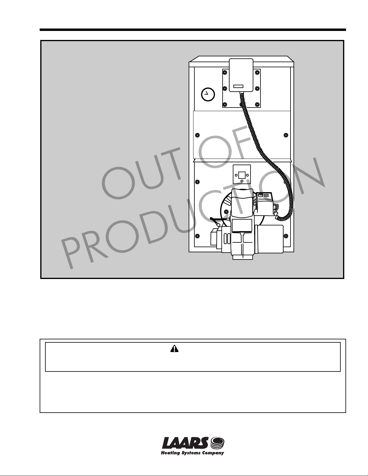
Horizon
Oil Fired Boiler
OUT OF
PRODUCTION
FOR YOUR SAFETY: This product must be installed and serviced by a professional service technician,
qualified in boiler installation and maintenance. Improper installation and/or operation could create
carbon monoxide gas in flue gases which could cause serious injury, property damage, or death.
Improper installation and/or operation will void the warranty.
WARNING
If the information in this manual is not followed exactly, a fire or explosion may result
causing property damage, personal injury or loss of life.
Do not store or use gasoline or other flammable vapors and liquids in the vicinity of this or
any other appliance.
Installation and service must be performed by a qualified installer, service agency, or fuel oil
supplier.
57-207B
A subsidiary of BRADFORD WHITE Corporation
Page 2

Page 2
LAARS Heating Systems Company
TABLE OF CONTENTS
SECTION 1.
General Information
1A. Freight Claims .............................................. 3
1B. General Information ...................................... 3
1C. Boiler Installation .......................................... 3
1D. Boiler Location .............................................. 3
1E. Boiler Clearances (minimum) ....................... 3
1F. Floor ............................................................. 3
1G. Combustion and Ventilation Air ..................... 3
1H. Chimney and Draft Requirements .................3
1I. Jacket (normally fitted).................................. 3
1J. Oil Burner (normally fitted) ............................ 3
1K. Boiler Controls (normally fitted) ..................... 3
1L. Oil ................................................................. 4
1M. Oil Storage and Pipe Layout ......................... 4
1N. Electrical Connections .................................. 4
OUT OF
1O. Operation
(using Honeywell L.8124A aquastat relay) .... 4
1P. Domestic Water Piping ................................. 4
SECTION 2.
Maintenance
2A. Cleaning the Boiler ....................................... 4
2B. Cleaning the Chimney................................... 4
2C. Servicing the Burner ..................................... 4
2D. Maintenance of the Tankless Coil ................. 5
2E. Coil Removal ................................................ 5
SECTION 3.
Part Numbers
................................................................... 11
PRODUCTION
Page 3

Horizon
Page 3
SECTION 1.
General Information
1A. Freight Claims
Inspection should be made of boiler and
components for damage upon arrival. Any claims for
damage should immediately be filed against the
carrier by the consignee.
1B. General Information
These boilers have been designed and
constructed according to the requirements of the
relevant ASME Codes using heavy gage steel plate
and boiler tubes. They are of the three pass horizontal
tube design using a reverse flame technique in the
boiler to impart a high heat transfer in the primary
heating zone before directing gases into the third pass.
The compact tubular third pass incorporates
special stainless steel flue gas baffles with extension
rods to allow full insertion of the baffles into the back
end of tubes where they are most effective.
A 5 gal/min. domestic hot water coil is located at
the top of the boiler in the hottest zone for ample hot
water supply. A unique feature of its attachment is the
raised coil flange which allows the use of clamping
bolts rather than studs, thereby eliminating water leaks
caused by broken studs.
Two ceraform lined doors provide easy access
for cleaning, the lower door with burner attached
remaining in position while the upper door is removed
for tube cleaning.
up burner and a test hole gives access for CO
draft readings.
enamel jacket and comes completely pre-assembled
for easy installation. Alternatively, it can be supplied
in knock-down form.
This boiler is designed for use in closed systems
where air is eliminated from the system and no more
oxygen is allowed to enter (typical baseboard or
radiator system). Do not directly connect this boiler
to a system utilizing rubber or plastic tubing which
has an oxygen permeation rating greater than 0.1
milligrams / liter / day. Damage to the boiler will
result and the warranty will be void (see warranty
section 4g).
1C. Boiler Installation
should be made to the National Fire Protection
Standard for Oil Burning Equipment - NFPA 31 Latest Edition.
PRODUCTION
A flame observation port is provided for setting-
The boiler is encased in a fully insulated baked
For recommended installation practice reference
OUT OF
and
2
Caution
1D. Boiler Location
The boiler should be positioned as near to the
chimney as possible and have a minimum smoke-pipe
connector length of 18".
1E. Boiler Clearances (minimum)
Top - 6"; Front - 24"; Rear - 6"; Sides - 6".
1F. Floor
The boiler must be mounted on a noncombustible masonry or cement floor with no
combustibles underneath.
1G. Combustion and Ventilation Air
To insure an adequate supply of fresh air for
combustion and ventilation an inlet and outlet opening
should be provided at floor and ceiling level. Each
opening must have a minimum of one square inch of
free area for every 1000 BTU/h of input or 140 square
inches per gallon of oil burned per hour. The openings
must not be in a position liable to blockage.
1H. Chimney and Draft Requirements
To assure the safe and proper operation of the oil
burner the boiler must be connected to a chimney
having sufficient draft at all times to evacuate the flue
gases to atmosphere. A draft regulator should be
installed in the smoke-pipe as near to the flue as
possible and adjusted to achieve an over fire draft of
0.01 in. W.C.
1I. Jacket (normally fitted)
If not fitted, assemble panels in accordance with
instructions in Figure 2.
1J. Oil Burner (normally fitted)
If not fitted, insert burner tube into boiler so that
it is recessed approximately 1/4" back from the inside
wall of door insulation, then clamp mounting flange
and bolt up to front-plate.
The burner should be wired and connected to the
oil line in accordance with the manufacturer’s
instructions.
1K. Boiler Controls (normally fitted)
If controls are supplied separately, fit them to the
boiler in the positions shown in Figure 2, with jacket
in place.
Circulator - 1 1/4' return tapping at rear of boiler.
Tridicator - temp./press. gauge - 1/2" tapping at
top of boiler.
Relief Valve - 3/4" tapping at top of boiler. Pipe
to safe place of discharge.
Aquastat Relief - L8124A - 3/4" tapping.
Fit a drain valve (not supplied) in the hydronic
return tee. Check that all connections are made water
tight.
Page 4
Page 4
LAARS Heating Systems Company
1L. Oil
Use only No. 2 Heating Oil. Do not use gasoline,
crankcase draining or any oil containing gasoline.
1M. Oil Storage and Pipe Layout
(See Figures 3 and 4)
Figure 3: One-pipe system - pipe and tank layout.
Figure 4: Two-pipe system - pipe and tank layout.
1N. Electrical Connections
All electrical wiring must conform to local codes
and/or the National Electrical Code ANSI / NFPA No.
70 - Latest Edition. The system must be electrically
grounded in accordance with the requirements of the
authority having jurisdiction or, in the absence of such
requirements, with the National Electrical Code
mentioned above.
1O. Operation
(using Honeywell L.8124A
aquastat relay)
A call for heat from the room thermostat causes
the relay to “make” the burner circuit and also feed
the circulator, provided the boiler water temperature is
above the low limit setting (usually 190° to 210°F).
The burner and circulator then continue to run until
the room thermostat is satisfied.
A high limit switch shuts off burner in the event
of water temperature exceeding the high limit setting,
usually 20° to 30°F above the low limit setting.
The low limit switch and circulator maintain
boiler water temperature for domestic hot water
service and prevents circulation of heating system
water if domestic water is not hot enough.
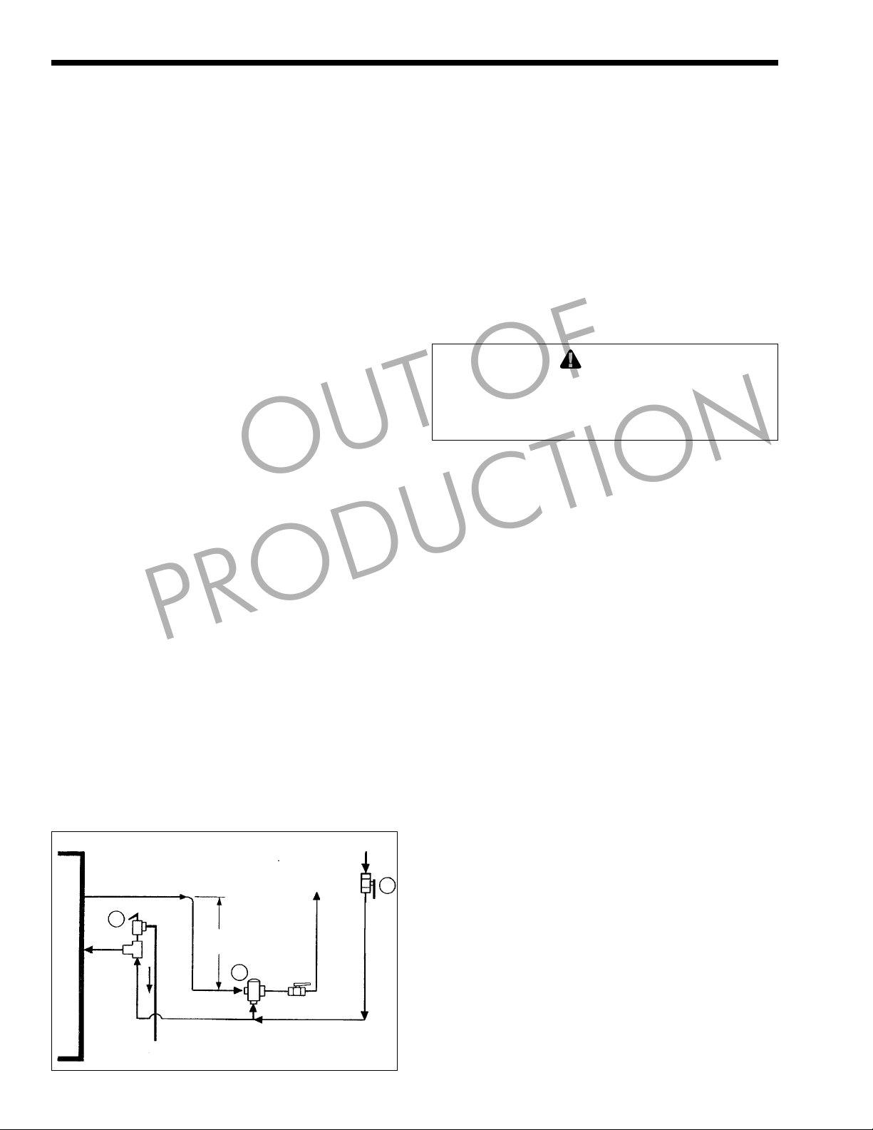
1P. Domestic Water Piping
Connect hot water tempering valve (12) “HOT”
port to hot water outlet from unit. This valve should
be mounted 8" to 12" below the outlet and set for
120°F mixed delivery temperature or as local codes
dictate.
PRODUCTION
OUT OF
Connect gate or shutoff valve (13) to tempering
valve (12) “MIX” port, and cold water inlet.
Connect pressure relief valve (11) (if required by
codes), maximum 150 PSI as close to the unit as
possible. No other valves or restrictions may be
installed between the DHW coil and the relief valve.
(DO NOT USE A TEMPERATURE/
PRESSURE RELIEF VALVE AS THIS IS NOT A
STORAGE HOT WATER HEATER).
SECTION 2.
Maintenance
WARNING
Flue gases are dangerous - do not operate boiler if
there is an escape of flue gas. Call a qualified
serviceman and have the entire flue and venting
system inspected.
2A. Cleaning the Boiler
To maintain the high thermal efficiency and a
long life from your boiler, it should be cleaned at least
once a year, preferably at the end of the heating
season. This is particularly important as rusting can
occur when the boiler is idle.
It is recommended that a service contract be
arranged with a properly equipped serviceman who
will be able to do the job efficiently and without mess.
1. Switch off electrical supply to the boiler.
2. Remove front cleaning cover.
3. Remove flue baffles and thoroughly brush out
flue tubes.
4. Remove flue deposits from flue collector box
using a vacuum nozzle through side cleaning
ports.
5. Vacuum out accumulated deposits from
combustion chamber through cleaning cover
opening.
6. Replace all parts, ensuring flue baffles are
correctly located and cleaning cover is tightly
sealed.
B
O
I
L
E
R
Figure 1.
13
11
8 - 12"
12
2B. Cleaning the Chimney
Sweep all soot deposits from chimney and
smoke-pipe once a year, preferably at the end of the
heating season. It is also advisable to inspect the
chimney and smoke-pipe at the beginning of heating
season as birds may have built their nest inside or
other material may be causing a blockage.
2C. Servicing the Burner
This should only be carried out by a trained and
licensed service technician in accordance with the
burner maker’s instructions.
Page 5

Horizon
Page 5
2D. Maintenance of the Tankless Coil
After several years of use, the water flow
through the coil may become restricted by mineral
deposits from the water. Mild accumulations may be
removed by an acid treatment, but your servicing
company can advise on the most satisfactory method
of cleaning or whether a replacement coil is
necessary.
OUT OF
2E. Coil Removal
1. Switch off electrical supply and turn off water
to boiler.
2. Drain the complete system.
3. Disconnect the pipe connections to the coil.
4. Unscrew the eight retaining bolts from coil plate.
5. Pull out coil and clean / fit replacement as
necessary.
6. Ensure gasket makes a water tight seal.
7. Refill & purge before returning system to
service.
PRODUCTION
Page 6

Page 6
LAARS Heating Systems Company
SIDE PANEL TO FRONT
PANEL FIXING
Vent Pipe
Hydronic Supply
with dip tube
PRODUCTION
Heavy gauge Enamelled Jacket
Tankless Coil 4 gal./min. in
Horizontal Fire Tube Design
Stainless Steel Flue Gas
Tubulators for optimum heat
transfer and highest efficiency
Flue Collector external fixing
hottest zone
Flue Cleaning Ports
no bolt corrosion
1. FIT FRONT PANEL (1)
OUT OF
2. ATTACH SIDE PANELS (2) AND (3) TO
BOTTOM OF BOILER AND FRONT
PANEL
3. FIX REAR PANELS (4) AND (5) TO SIDE
PANELS
4. FIT TOP PANEL (6)
Relief Valve
Bolted Coil Flange for easy
re-tightening - no Studs to
break
Aquastat Relay
Domestic Water Connections
Removable Flue Cover for
easy tube cleaning
and Draft Test Plug
CO
2
Flame Observation Glass
CO2 and Draft Test Plug
Extra Heavy Duty Insulation
for low stand-by losses
Hydronic Return
Sludge Clean-out Socket
Figure 2.
Flame Retention Oil Burner
Glass fiber Rope for positive
gas tight seal
Flame Reverse Combustion
Page 7

Horizon
Aquastat Relay
L8124A ¾" N.P.T.
Wiring Conduit
Supply Pipe
Vent
Relief Valve
Tridicator ½"
N.P.T.
to Circulator
Tankless Domestic
Hot Water Coil ½" N.P.T.
Wiring Conduit to
OUT OF
Burner
Page 7
Draft Regulator
and Smoke Pipe
(not supplied)
Flame Observation
Glass
PRODUCTION
Oil Burner
Tapping NPT
Tankless Coil ¾"
Tridicator ¼"
Hydronic Return 1¼"
Hydronic Supply 1¼"
Aquastat Well ¾"
Figure 3.
Relief Valve Fitting ¾"
Alternate Hydronic Return 1¼"
Page 8

Page 8
Tankless Coil
½" N.P.T.
LAARS Heating Systems Company
C
H
3½"
Relief Valve — ¾" N.P.T.
Supply — J N.P.T.
G
E
B
Fire Sight
A
Glass
Domestic
Hot Out
Domestic
Cold In
Aquastat
Well
¾" N.P.T.
8¾"
Figure 4.
F
D
FRONT SIDE REAR
Dimensions REF HC 100 HC 125 HC 145 HC 175 HC 205 HC 240 HC 270 HC 300
Jacket Height A 39" 39" 42" 42" 45¾" 45¾" 45¾" 45¾"
Jacket Width B 21" 21" 23" 23" 25" 25" 25" 25"
Jacket Length C 21" 21" 23" 23" 25" 25" 29" 29"
Overall Length D 32" 32" 34" 34" 36" 36" 40" 40"
Smoke Outlet Height E 24½" 24½" 27" 27" 29½" 29½" 29½" 29½"
Burner Center Line F 10¾" 10¾" 11¾" 11¾" 12½" 12½" 12½" 12½"
Smoke Outlet Diameter G 6" 6" 6" 6" 8" 8" 8" 8"
Smoke Box H 1¾" 1¾" 1¾" 1¾" 2½" 2½" 2½" 2½"
Supply Size Water I 1¼" 1¼" 1¼" 1¼" 1½" 1½" 1½" 1½"
PRODUCTION
Specification HC 100 HC 125 HC 145 HC 175 HC 205 HC 240 HC 270 HC 300
D.O.E. Heating Capacity 100 125 145 175 205 240 270 300
Net Output M.B.H. 87 109 126 152 178 209 235 261
A.F.U.E. % 84.2 84 85.8 85.2 85.4 84.2 85.2 84.4
Firing Rate G.P.H. .85 1 1.25 1.50 1.75 2.00 2.25 2.50
Net Stack Temperature 333 371 319 354 325 350 330 360
Water Capaqcity Gal. 21 21 34 34 42 42 48 48
Coil Capacity G.P.M. 5 5 5 5 5 5 5 5
Approx. Weight lbs. 494 494 608 608 764 764 810 810
OUT OF
8"
Return — J N.P.T.
Drain Valve
7"
Burner Head Type
HC100 AFG F3 3 5/8" 4 1/4" x 2 7/16" .75 x 70°A
HC125 AFG F3 3 5/8" 4 1/4" x 2 7/16" .90 x 80°B
HC145 AFG F6 2 3/4" 4 1/4" x 2 7/16" 1.10 x 80°B
HC175 AFG F6 2 3/4" 4 1/4" x 2 7/16" 1.25 x 80°B
HC205 AFG F16 2 3/4" 4 1/4" x 2 7/16" 1.50 x 80°A
HC240 AFG F16 2 3/4" 4 1/4" x 2 7/16" 1.75 x 80°B
HC270 AFG F22 2 3/4" 4 1/4" x 2 7/16" 2.00 x 80°B
HC300 AFG F22 2 3/4" 4 1/4" x 2 7/16" 2.25 x 80°B
Static
Plate Stop
Blower Wheel Nozzle Type
Page 9

Horizon
Page 9
Air Vent
Fill Pipe
Figure 5. One-Pipe System.
1¼" min
Valve
OUT OF
Air Vent 1¼" min.
Oil Tank
Filter
Fill Pipe
"H"
Valve
"P"
Filter
Burner
Burner
Boiler
Boiler
Oil Tank
PRODUCTION
Figure 6. Two-Pipe System.
PIPE LENGTHS
One Pipe Gravity System
"H"
3/8" O.D. 1/2" O.D.
ft ft ft
0
1½ 33 65
3 65 130
5 130 260
6½ 195 325
WARNING
The height should not exceed 13 feet.
WARNING
The vacuum must not excedd 11.44 HG (11.44
inches of Mercury). Burner is shipped from the
factory set up for two pipe system.
"H"
PIPE LENGTHS
Two Pipe Lift System
"H"
3/8" O.D. 1/2" O.D.
ft ft ft
0 115 330
1½ 100 330
3 80 330
5 65 295
6½ 50 230
9½ 25 100
11 20 65
Important
An external filter must be placed in the fuel line
between the fuel tank and the burner pump.
Page 10

Page 10
LAARS Heating Systems Company
Power supply provides disconnect means & overload protection as required.
24V
Room Thermostat
1K
Circulator
Switch
OUT OF
1K1
L1 (Hot)
Power Supply
120V
L2
Low Limit
Circulator
PRODUCTION
Hi Limit
1K2
Heating Circulator
Aquastat Relay L8124A
Oil Burner
Relay
Figure 7.
Wiring Arrangement for HC Boiler
Controlling Operation of Boiler and Circulator
Page 11

Horizon
SECTION 3.
Part Numbers
Page 11
Part Number Description Size
57-002 Boiler Body ............................... 100/125
57-072 Inspection Cover Assembly ..... 100/125
57-090 Burner Door Assembly ............ 100/125
57-136 Flue Cover Assembly .............. 100/125
57-170 Front Panel Assembly ............. 100/125
57-164 Left Panel Assembly ................ 100/125
57-154 Right Panel Assembly ............. 100/125
57-194 Top Panel Assembly................ 100/125
57-176 Rear Upper Panel Assembly ... 100/125
57-186 Rear Bottom Assembly ............ 100/125
57-145-2 Target, Wall ............................. 100/125
57-146 Baffle, 110/125 (13), 145/175 (18), ...All
205/240 (26)
59-002 Boiler Body ............................... 145/175
59-072 Inspection Cover Assembly ..... 145/175
59-090 Burner Door Assembly ............ 145/175
59-136 Flue Cover Assembly .............. 145/175
OUT OF
Part Number Description Size
59-170 Front Panel Assembly 145/175
59-164 Left Panel Assembly ................ 145/175
59-154 Right Panel Assembly ............. 145/175
59-194 Top Panel Assembly................ 145/175
59-176 Rear Upper Panel Assembly ... 145/175
59-186 Rear Bottom Assembly ............ 145/175
59-145-2 Target Wall .............................. 145/175
61-002 Boiler Body ............................... 205/240
61-072 Inspection Cover Assembly ..... 205/240
61-090 Burner Door Assembly ............ 205/240
61-136 Flue Cover Assembly .............. 205/240
61-170 Front Panel Assembly ............. 205/240
61-164 Left Panel Assembly ................ 205/240
61-154 Right Panel Assembly ............. 205/240
61-194 Top Panel Assembly................ 205/240
61-176 Rear Upper Panel Assembly ... 205/240
61-186 Rear Bottom Assembly ............ 205/240
61-145-2 Target Wall .............................. 205/240
PRODUCTION
Page 12

OUT OF
PRODUCTION
57-207B
800.900.9276 • Fax 800.559.1583 (Customer Service, Service Advisors)
20 Industrial Way, Rochester, NH 03867 • 603.335.6300 • Fax 603.335.3355
1869 Sismet Road, Mississauga, Ontario, Canada L4W 1W8 • 905.238.0100 • Fax 905.366.0130
www.Laars.com Litho in U.S.A. © Laars Heating Systems 0805 Document 1104B
 Loading...