

Laars EBP0110, EBP0175, EDP0110, EDP0175, EDN0110 Installation, Operation And Maintanance Manual
...
Installation, Operation and Maintenance Instructions Document 1187B
Installation,
Operation and
Maintenance
Instructions for
Endurance
EBP Series Modulating Combination Boiler
(natural or propane gas)
EDP Series Modulating Hydronic Boiler
(natural or propane gas)
EDN Series Modulating Boiler, non ferrous
(natural or propane gas)
WARNING
FOR YOUR SAFETY: This product must be installed and serviced by a professional service technician,
qualified in hot water boiler installation and maintenance. Improper installation and/or operation could
create carbon monoxide gas in flue gases which could cause serious injury, property damage, or
death. Improper installation and/or operation will void the warranty. As an additional measure of safety,
Laars strongly recommends installation of suitable carbon monoxide detectors in the vicinity of this
appliance and in any adjacent occupied spaces.
If the information in this manual is not
WARNING
followed exactly, a fire or explosion may
result causing property damage, personal
injury or loss of life.
Do not store or use gasoline or other
flammable vapors and liquids in the vicinity
of this or any other appliance.
WHAT TO DO IF YOU SMELL GAS
• Do not try to light any appliance.
• Do not touch any electrical switch; do not
use any phone in your building.
• Immediately call your gas supplier from a
nearby phone. Follow the gas supplier's
instructions.
• If you cannot reach your gas supplier, call
the fire department.
Installation and service must be performed by
a qualified installer, service agency, or gas
supplier.
Assurez-vous de bien suivres les instructions
données dans cette notice pour réduire au
minimum le risque d’incendie ou d’explosion ou
pour éviter tout dommage matériel, toute
blessure ou la mort.
Ne pas entreposer ni utiliser d’essence ni
d’autres vapeurs ou liquides inflammables dans
le voisinage de cet appareil ou de tout autre
appareil.
QUE FAIRE SI VOUS SENTEZ UNE ODEUR DE GAZ:
• Ne pas tenter d’allumer d’appareils.
• Ne touchez à aucun interrupteur. Ne pas vous
servir des téléphones dansle bâtiment où vous
vous trouvez.
• Appelez immédiatement votre fournisseur de
gaz depuis un voisin. Suivez les instructions
du fournisseur.
• Si vous ne pouvez rejoindre le fournisseur de
gaz, appelez le sservice des incendies.
L’installation et l’entretien doivent être assurés par
un installateur ou un service d’entretien qualifié ou
par le fournisseur de gaz.
AVERTISSEMENT
H2313500B
A subsidiary of BRADFORD WHITE Corporation

Page 2
TABLE OF CONTENTS
SECTION 1.
General Information
1.1 Introduction................................................... 3
1.2 Codes and Standards................................... 3
1.3 Unpacking the Appliance.............................. 4
1.4 Locating the Appliance ................................. 4
1.5 Clearances ................................................... 4
SECTION 2.
Venting Options
2.1 Concentric Direct Vent ................................. 5
2.1.1 Concentric Vent Description ......................... 5
2.1.2 Laars Concentric Vent Kits ........................... 5
2.1.3 Horizontal Concentric Vent Location ............ 5
2.2 Stainless Steel Single Pipe Horizontal
and Vertical Vents — Category IV ................ 9
2.3 Air Source For Combustion (when not
ducted to the Endurance) ........................... 11
2.3.1 Air From Inside the Building ....................... 11
2.3.2 All Air From Outdoors .................................11
2.3.3 Connecting Special Gas Vent to the
Appliance.................................................... 12
2.4 Non-Concentric Combustion Air ................. 12
SECTION 3.
Gas Piping
3.1 Gas Piping .................................................. 12
3.2 Domestic Water Piping (EBP only) ............. 13
3.3 Anti-Freeze — Domestic Water .................. 14
SECTION 4.
Hydronic Heat Piping
4.1 Hydronic Piping .......................................... 14
4.2 Using in a Combined Hot Water Heating
and Chilled Water Cooling System ............. 17
4.3 Water Quality and Treatment ..................... 17
4.4 Anti-Freeze ................................................. 17
4.4.1 Endurance Boiler Low
Temperature Feature ................................. 17
4.4.2 Anti-Freeze Boiler Additives ....................... 17
SECTION 5.
Electrical Connections
5.1 Electrical Connections ................................ 20
SECTION 6.
Using the Boiler Control
6.1 Front Panel Display .................................... 22
6.2 Control Logic .............................................. 22
6.3 View Menu.................................................. 22
6.4 Setpoint Menu ............................................ 24
6.4.1 “SP” Supply Temperature ........................... 24
6.4.2 “PO” Pump Operation ................................. 24
6.4.3 “Pd” Pump Delay ........................................ 24
6.4.4 “Oar” Outdoor Reset................................... 24
6.4.5 “Oal” Minimum Outdoor Reset Point .......... 25
6.4.6 “rc” Outdoor Reset Ratio ............................ 25
6.4.7 “oTo” Warm Outdoor Shutdown ................. 25
6.4.8 “unl” Temperature Units ............................. 25
LAARS Heating Systems
6.4.9 “Add” Control Address ................................ 25
6.4.10 “Dif” Burner On Differential ......................... 25
6.5 Calculated Control Values .......................... 25
6.5.1 ACV Release (EBP only) ............................ 25
6.5.2 Tank Charge Setting (EBP only) ................ 25
6.5.3 Burner On Point.......................................... 25
6.5.4 Modulation Point......................................... 25
6.6 Other Control Functions ............................. 25
6.6.1 Using Buttons on Control ........................... 25
6.6.2 Alarm Acknowledge.................................... 26
6.6.3 Power On/Off .............................................. 26
6.6.4 Low Fire Hold ............................................. 26
6.6.5 High Fire Hold ............................................ 26
6.6.6 Pump Operation ......................................... 26
6.6.7 Anti-Condense Valve Operation ................. 26
6.6.8 Field-Supplied Outdoor Reset Controls ...... 27
SECTION 7.
Boiler Start Up
7.1 Removal of Boiler From Common Vent ...... 27
7.2 Filling the System ....................................... 28
7.3 Firing Burner............................................... 28
SECTION 8.
Maintenance and Component Description
8.1 Unit Pump................................................... 29
8.2 Gas Valve ................................................... 29
8.3 Safety Limit Switch ..................................... 29
8.4 Boiler Control.............................................. 29
8.5 Ignition Control ........................................... 30
8.6 Ignitor / Flame Sensor Assembly................ 30
8.7 Transformer ................................................ 30
8.8 PMW Board ................................................ 30
8.9 Blower ........................................................ 30
8.10 Transfer Tank (EBP) .................................. 30
8.11 Thermostatic Union (EDP/EDN) ................. 31
8.12 Cleaning the Boiler Coil .............................. 31
SECTION 9.
Servicing
9.1 Sequence of Operation .............................. 31
9.2.1 Fault Code Identification ............................. 33
9.2.2 Fault Correction .......................................... 33
9.2.3 Resolving Lockouts (LO) ............................ 33
SECTION 10.
Air Orifice and Gas Valve Adjustment
................................................................... 35
SECTION 11.
Symptom Evaluations
11.1 Delayed Ignition.......................................... 35
11.2 Short Cycling .............................................. 36
11.3 Noisy Operation.......................................... 36
11.4 Insufficient Hot Water (EBP only) ............... 36
11.5 High Gas Consumption .............................. 37
SECTION 12.
Parts Identification
................................................................... 38
Endurance
Page 3
SECTION 1.
General Information
1.1 Introduction
EBP - This appliance is a low pressure, direct
vent, hot water boiler that provides priority domestic
hot water on demand as well as hydronic space
heating. The unit has a twenty gallon tank which holds
boiler water (as opposed to domestic water storage).
The boiler water is kept hot at all times to
provide immediate response to call for heat or
domestic water. Domestic water is heated by the boiler
water through a stainless steel plate heat exchanger.
EDP/EDN - This appliance is a low pressure,
direct vent, cold start hot water boiler that provides
heat for hydronic space heating. The model number
structure is shown in Figure 3.
Both appliances incorporate a circulating pump
and a bypass loop, and provide circulation for the
heating system and adequate flow for its own needs.
It may be necessary to install a system circulator to
achieve the required flow rate through the system.
Both appliances feature a forced draft, premixed
combustion system. All air for combustion is supplied
with the gas to the burner (flame holder). Both the
intake air and the gas are metered through separate
orifices before entering the combustion air blower. The
blower forces the air/fuel mixture through the flame
holder and into the combustion chamber. The mixture
is ignited from the hot surface ignitor and burns. Hot
gases are forced out between the passes of the heat
exchanger into the flue collector. Flue gases are
discharged into the outside atmosphere through the
vent terminal.
The appliance can operate with a concentric vent
system that will provide outside air for combustion.
Other venting arrangements can be provided for the
appliance to include an alternative 50 equivalent feet
maximum horizontal or condensate trapped vertical
vent.
1.2 Codes and Standards
The Endurance may be a direct vent or Category
IV Boiler. All installations must be made in
accordance with:
a. The National Fuel Gas Code, ANSI Z223.1/
NFPA 54 latest edition, or
b. CSA B149.1 Natural Gas and Propane
Installation Code.
c. The requirements of the local utility or other
authorities having jurisdiction take precedence
over the general instructions contained herein.
All electrical wiring is to be done in accordance with:.
a. The National Electrical Code (NFPA 70), latest
edition or
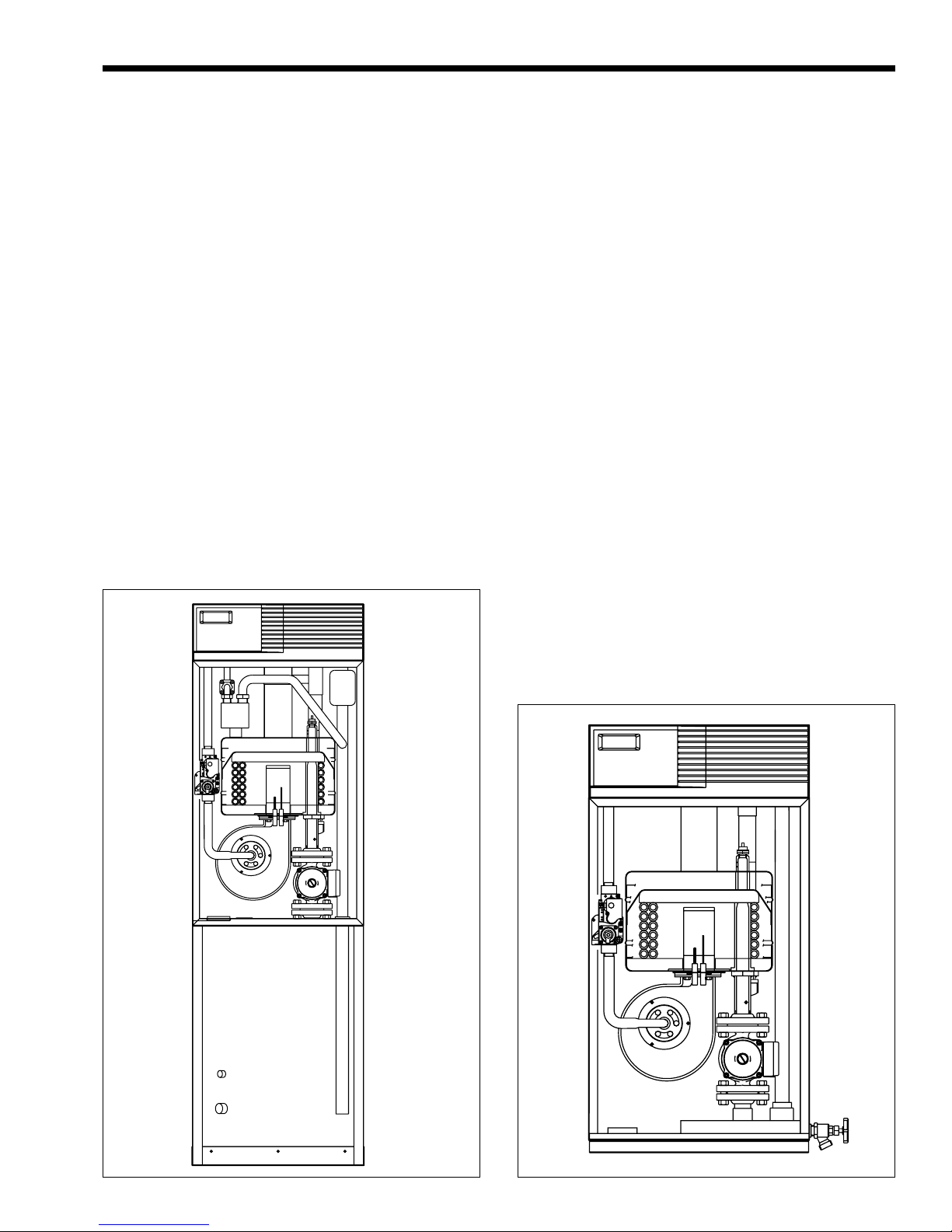
Figure 1. Combo Heating/Domestic Water (Model EBP).
Figure 2. Heating Unit (Model EDP/EDN).
Page 4
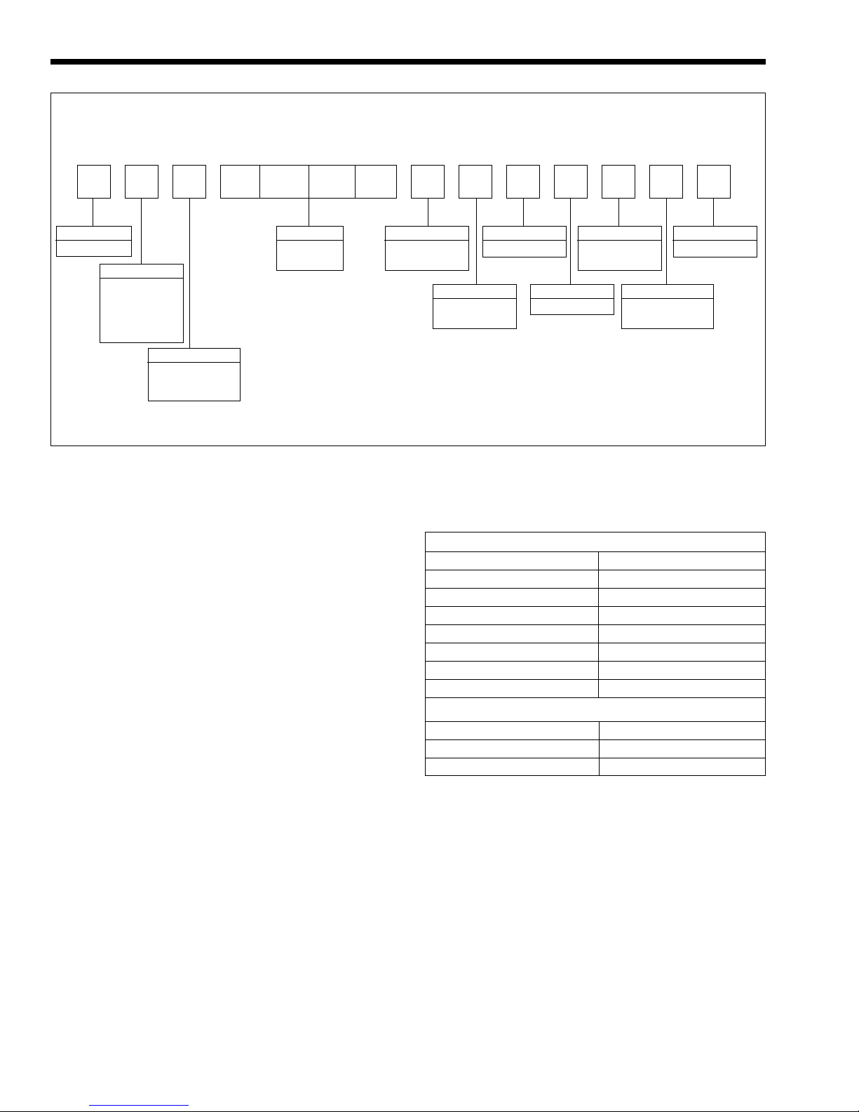
1234567891011121314
E IF2 X
LAARS Heating Systems
Prod. Line
E = Endurance
Usage
B = Combination,
Heating &
Domestic
Water
D =Heating Only
Type
P =Standard
N =Non Ferrous
(ED Units Only)
Figure 3. Model Structure.
BTU Input
0 1 1 0
0 1 7 5
b. The Canadian Electrical Code (CSA C22.1),
latest edition.
c. All applicable local installation codes must also
be adhered to.
All vent installations must be made in accordance with:
a. The applicable venting requirements of the
National Fuel Gas Code (ANSI Z223.1/NFPA
54), latest edition; or
b. in Canada, The Natural Gas and Propane
Installation Code (CSA B149.1), latest edition.
All applicable provisions of local building codes
should also be adhered to.
Fuel
N =Natural Gas
P =Propane
A = 0' - 5,000'
H =Over 5,000'
Altitude
Location
I = Indoor
Firing Mode
F = Modulating
Revision
2 = Second
Revision
Country of Sale
A = USA & Canada
R =Russia
1.5 Clearances
The dimension and criteria in Table 1 should be
followed when choosing the location for the unit.
Minimum Clearances From Combustible Materials
Back 1 inch 25mm
Left Side 1 inch 25mm
Right Side 1 inch 25mm
Front 1 inch 25mm
Top (Alcove Install) 1 inch 25mm
Top (Closet Install)* 22 inches 559mm
Vent: Concentric, Direct 0 inch 0mm
Vent: Category 3 inches 76mm
Options Code
X =None
1.3 Unpacking the Appliance
Remove all packing and tie down materials.
Make immediate claims (to the carrier) if the appliance
and its packaging are damaged.
1.4 Locating the Appliance
The appliance is designed for installation on
combustible flooring, in alcoves, basements, closets, or
utility rooms. It must NOT be installed on carpeting.
IF INSTALLED IN A FINISHED AREA,
PROVISION SHOULD BE MADE FOR DRAINAGE
OF ANY ACCIDENTAL SPILLAGE OR LEAKAGE.
The location for the unit should be chosen with
regard to venting dimensions, convenient access to
piping, and accessibility for service and cleaning.
The boiler shall be installed so that the gas
ignition system components are protected from water
(dripping, spraying, rain, etc.) during appliance
operation or service (circulator replacement, control
replacement, etc.).
Suggested Serviceability Clearances
Front 18 inches 457mm
Left Side 6 inches 152mm
Right Side 6 inches 152mm
*Minimum closet height 6'9" 206 cm
Table 1. Clearances.
SECTION 2.
Venting Options
The Endurance boilers are certified as direct
vent, sealed combustion boilers, when vented using
one of the following two methods:
1) Concentric direct vent, which has a flue gas pipe
inside a combustion air pipe.
2) Non-concentric direct vent, using separate pipes
for the flue gases and the combustion air.
The Endurance boilers can also take air from the
space (when properly sized), and be vented as a
Category IV appliance.
Endurance
Page 5
The following sections describe the requirements
for each of these methods.
IMPORTANT NOTE REGARDING ENDURANCE
VENTING: Regardless of the venting arrangement
being used, the flue gas vent material used with
the Endurance MUST be stainless steel special
gas vent listed to U.L. Standard 1738 and U.L.C.
Standard 636. Endurance flue gases must never
be vented into a masonry chimney or vented with
B-vent or other galvanized vent material.
Endurance units are not permitted to be common
vented with any other appliance(s), including
other Endurance appliances.
2.1 Concentric Direct Vent
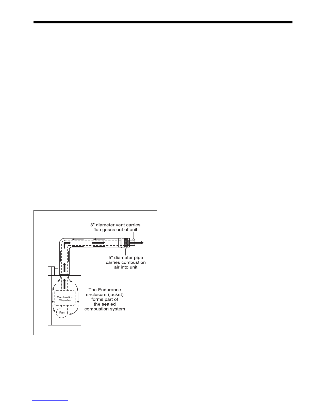
2.1.1 Concentric Vent Description
Endurance concentric direct vent is a sealedcombustion system. It can be used for vent systems
with a maximum of 15 linear feet (4.6m) and three
elbows. All of the air is drawn in from the outside
through a 5" stainless steel outer pipe. Flue gases are
vented through a 3" stainless steel pipe that is
positioned inside the 5" intake pipe. Hot flue gases are
surrounded by the intake flow of cooler outdoor air
(see Figure 4). Laars offers two concentric vent kits,
described in section 2.1.2. Laars concentric vents may
be installed through, and be in contact with,
combustible materials.
Figure 4. Combustion Air and Flue Gas Paths.
2.1.2 Laars Concentric Vent Kits
The Endurance is certified with a maximum of
15 linear feet (4.6m) of concentric piping and three
sets of elbows. There are two concentric vent kits
offered by Laars. Both kits, and all Laars Endurance
vent material meet the requirements of U.L. Standard
1738 and U.L.C. Standard 636. The horizontal vent kit
is part number 2400-009. The vertical vent kit is part
number 2400-011. See Figures 5 and 6, which show
the components included with the kits and venting
configurations. Installation instructions are included
with the kits. Rules for concentric venting, vent
material and vent terminal placement are discussed in
the rest of section 2 of this manual.
For additional length, and/or fittings, to extend
the kits to maximum 15 linear feet (4.6m) and three
elbows, individual components are available. These
components are shown in Figure 7.
2.1.3 Horizontal Concentric Vent
Location
The centerline of the vent opening must be at
least 16-1/2" (42cm) above grade, outside. Should it
be impossible to locate the opening centerline 16-1/2"
(42cm) above grade, use optional concentric vent
terminal extension (part number 2400-428), shown in
Figure 7.
In the U.S., vent terminals must be at least 3 feet
(0.9m) above any forced air inlet located within 10
feet (3.0m). In Canada, vent terminals must be at least
6 feet (1.8m) from any forced air inlet.
In the U.S., a direct vent terminal must be at least
12" (30cm) from any window or door that may be
opened, or any other nonmechanical opening. For an
Endurance that is not direct vented (vented as
Category IV), the vent terminal must be at least 4 feet
(1.2m) below or to the side of, and 12" (30cm) above
any such opening.
In Canada, a direct vent or non-direct vent
terminal must be at least 36" (91cm) from any window
or door that may be opened, or any other nonmechanical opening.
The vent opening should be well away from
shrubbery or other obstructions that would prevent
free air flow to and from the vent terminal.
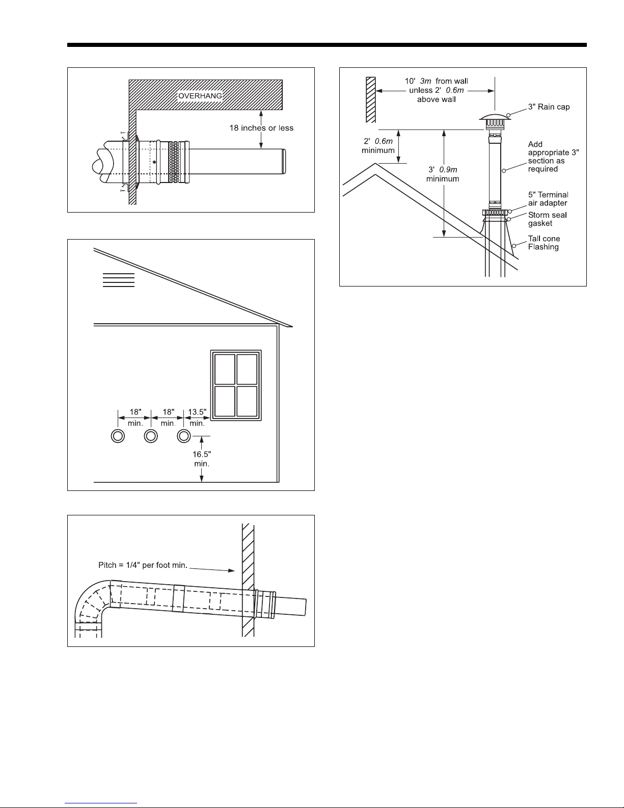
If the vent terminal location chosen is less than
18" (46cm) below an overhang, the 3" vent pipe must
extend to the outside edge of the overhang, to prevent
the accumulation of flue gas (see Figure 9).
Accumulating flue gas can contaminate the
combustion air, causing nuisance lockouts of the
ignition system. In addition, accumulation of flue
gases can settle on, and damage the structure’s
surfaces.
Vent terminals must not terminate in a location
where condensate or vapor may be a nuisance, hazard,
or could be a detriment to other equipment. See Figure
8 for more detail concerning vent terminal placement
in the U.S. and Canada.
Do not locate the vent terminal where blockage
by snow is a possibility, or where flue products could
strike against building materials and cause
degradation.
When multiple Endurance units are used, the
concentric vent terminals may be side-by-side,
Page 6
LAARS Heating Systems
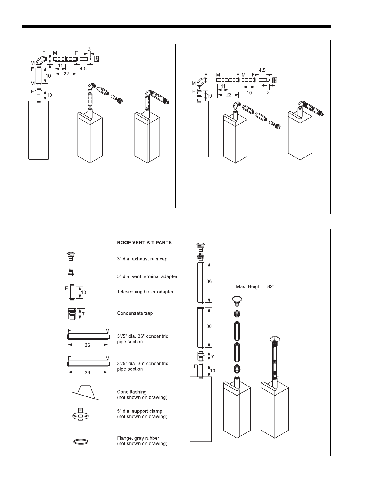
Configuration 1:
Maximum horizontal = 28"
Maximum vertical = 26"
(Measurements are from the centerlineof the venting to
the boiler top or face of outside wall.)
Dimensions shown in inches.
Figure 5. Horizontal Vent Kit 2400-009.
Configuration 2:
Maximum horizontal = 38"
Maximum vertical = 16"
(Measurements are from the centerline of the venting to
the boiler top or face of outside wall.)
Dimensions shown in inches.
Figure 6. Vertical Vent Kit 2400-011.
Endurance
Page 7
Figure 7. Concentric Vent Parts.
Dimensions shown in inches.
Page 8
LAARS Heating Systems
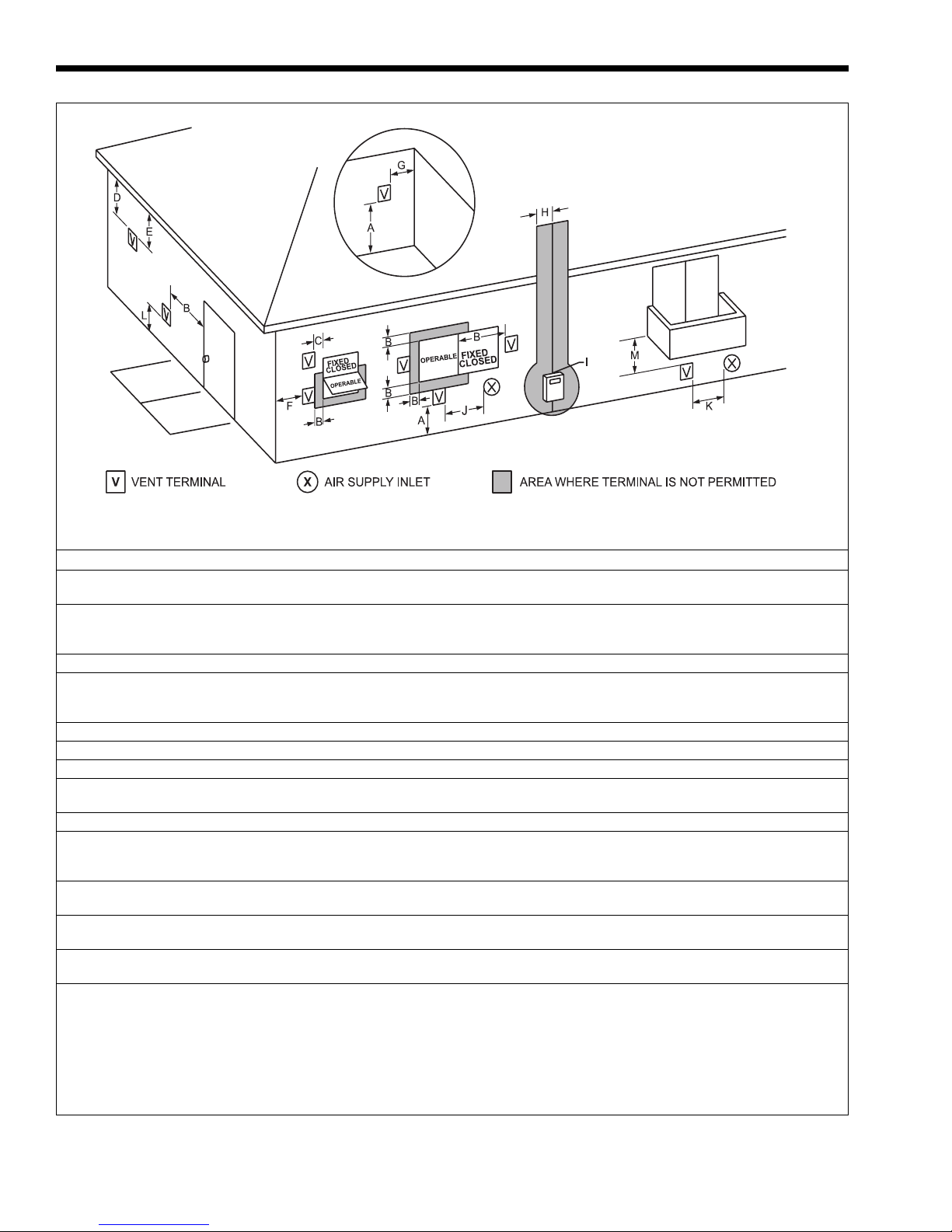
U.S. Installations (see note 1) Canadian Installations (see note 2)
A= Clearance above grade, veranda, porch, 12 inches (30 cm) 12 inches (30 cm)
deck, or balcony
B= Clearance to window or door that may Direct Vent Only: 12 inches (30 cm)
be opened Other Than Direct Vent: 4 feet (1.2 m) below or 36 inches (91 cm)
C= Clearance to permanently closed window See note 4 See note 5
D= Vertical clearance to ventilated soffit located
above the terminal within a horizontal See note 4 See note 5
distance of 2 feet (61cm) from the center line of the terminal
E= Clearance to unventilated soffit See note 4 See note 5
F= Clearance to outside corner See note 4 See note 5
G= Clearance to inside corner See note 4 See note 5
H= Clearance to each side of center line See note 4 3 feet (91 cm) within a height 15 feet
extended above meter/regulator assembly above the meter/regulator assembly
I= Clearance to service regulator vent outlet See note 4 3 feet (91 cm)
J= Clearance to nonmechanical air supply Direct Vent Only: 12 inches (30 cm)
inlet to building or the combustion air inlet Other Than Direct Vent: 4 feet (1.2 m) below or 36 inches (91 cm)
to any other appliance to side of opening; 1 foot (30 cm) above opening
K= Clearance to a mechanical air supply inlet 3 feet (91 cm) above if within 10 feet (3 m) 6 feet (1.83 m)
L= Clearance above paved sidewalk or paved Vent termination not allowed in this location Vent termination not allowed in this
driveway located on public property location
M= Clearance under veranda, porch, deck, See note 4 12 inches (30 cm) (see note 3)
or balcony
Notes:
1. In accordance with the current ANSI Z223.1 / NFPA 54 National Fuel Gas Code.
2. In accordance with the current CAN/CGA-B149 Installation Codes.
3. Permitted only if veranda, porch, deck, or balcony is fully open on a minimum of two sides beneath the floor.
4. For clearances not specified in ANSI Z223.1 / NFPA 54, clearance is in accordance with local installation codes and the requirements of
the gas supplier.
5. For clearances not specified in CAN/CGA-B149, clearance is in accordance with local installation codes and the requirements of the gas
supplier.
to side of opening; 1 foot (30 cm) above opening
horizontally
Figure 8. Vent Terminal Clearance.
Endurance
Figure 9. Clearance from Overhang.
Figure 10. Multiple Concentric Vent Clearances.
Page 9
Figure 12. Vertical Vent Terminal Placement.
The vertical vent terminal must be placed such
that the bottom of the vent cap is at least 2-feet (0.6m)
above any structure (such as the peak of a roof or
adjacent wall) within 10 feet (3.0m), and must be at
least 3 feet (0.9m) above where the vent pipe exits the
roof (see Figure 12).
When vertical vent systems have horizontal
components, they must have a condensate drip tee in
the offset. All horizontal portions of the vent system
must slope a minimum 1/4" per foot toward the
condensate drip tee. Laars vertical vent kit and
individual venting components have condensate tees
that work in a vertical vent system, and therefore it is
not necessary to have an offset in a vertical vent
system that uses these parts.
Figure 11. Vent System Pitch.
provided that they are at least 18" (46cm) apart,
centerline to centerline (see Figure 10).
A horizontal vent system must pitch downward,
toward the terminal and away from the Endurance, as
shown in Figure 11. It must pitch at least 1/4" per foot
(21mm per meter). Be sure to take this into
consideration when choosing the vent terminal
location.
2.2 Stainless Steel Single Pipe Horizontal
and Vertical Vents – Category IV
Stainless steel special gas vent listed to U.L.
Standard 1738 and U.L.C. Standard 636 must be used
to vent all models. Three-inch or 4-inch material can
be used. Vent pipe and fittings are manufactured to
these standards by HeatFab, Inc. under the trade name
of Saf-T Vent
®
Vent
, and by ProTech Systems, Inc. under the trade
name FasNSeal
manufacturer’s instructions regarding design, location
and assembly of the vent system.
The appliance may be vented with any number
of elbows or fittings, providing that the maximum
equivalent feet of venting is not exceeded. Equivalent
feet of vent material is shown in table 2, along with
information about vent temperature and pressure.
Elbows (90°) in the vent system shall be considered to
be 5 equivalent feet (1.5m).
A horizontal vent system must pitch downward,
toward the terminal and away from the Endurance, as
shown in Figure 11. It must pitch at least 1/4" per foot
®
, by Z-Flex™ under the trade name of Z-
®
. Follow the special gas vent
Page 10
LAARS Heating Systems
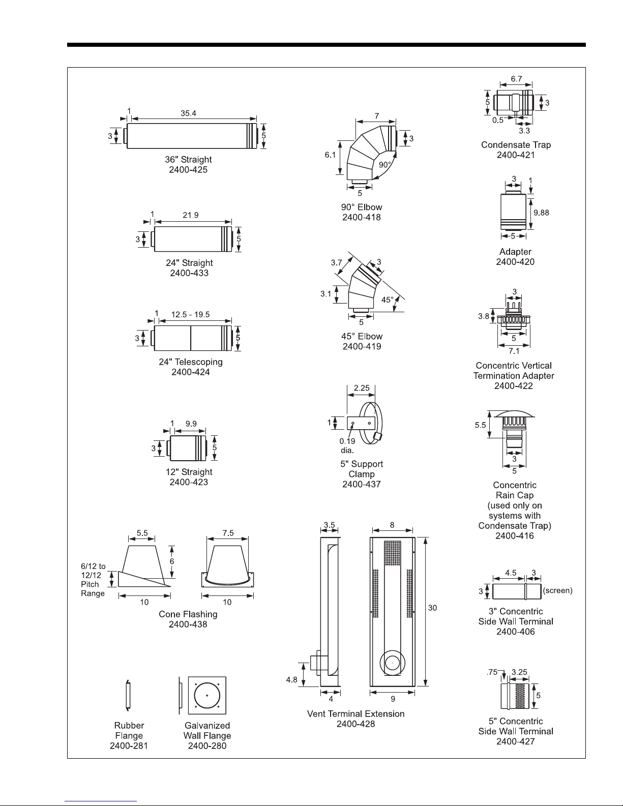
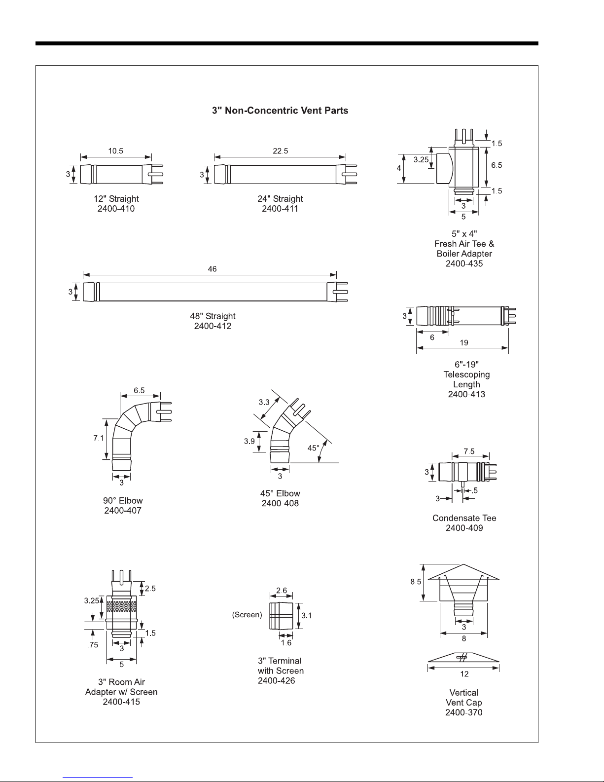
Figure 13. 3" Vent Parts.
Dimensions shown in inches.
Endurance
Page 11
Minimum clearance from
combustibles (vent) U.S.* 3" 8cm
Minimum clearance from
combustibles (vent) Canada 6" 15cm
Max. flue gas temp. 325°F 163°C
Max vent pressure 1.5" w.c. 0.4kPa
Max. equivalent ft. of 3" venting (any 50 15
combination of horizontal or vertical) equiv. feet equiv. meters
Max. equivalent ft. of 4" venting (any 100 30
combination of horizontal or vertical) equiv. feet equiv. meters
*Note: To use 3" (8cm) clearance, the vent must be open on at
least one side. If fully enclosed, clearance is 6" (15cm)
Table 2. Category IV Vent Parameters.
(21mm per meter). Be sure to take this into
consideration when choosing the vent terminal
location.
For applications requiring vertical venting
through a roof, the same limitations for length and
fittings apply (see Table 2). Vertical vents greater than
7 feet (2.1m) in length must use a condensate trap.
When vertical vent systems have horizontal
components, they must have a condensate drip tee in
the offset. All horizontal portions of the vent system
must slope a minimum 1/4" per foot toward the
condensate drip tee. Laars vertical vent kit and
individual venting components have condensate tees
that work in a vertical vent system, and therefore it is
not necessary to have an offset in a vertical vent
systems that use these parts.
The vertical vent terminal must be placed such
that the bottom of the vent cap is at least 2-feet (0.6m)
above any structure (such as the peak of a roof or
adjacent wall) within 10 feet (3.0m), and must be at
least 3 feet (0.9m) above where the vent pipe exits the
roof (see Figure 12).
Laars offers 3" vent parts for non-concentric
venting, including an in-line condensate tee and vent
caps for vertical venting. See Figure 13 for 3" vent
parts, and Figure 15 for an example of the inline
condensate in a vertical vent system.
IMPORTANT NOTE REGARDING ENDURANCE
VENTING: Regardless of the venting arrangement
being used, the flue gas vent material used with the
Endurance MUST be stainless steel special gas
vent listed to U.L. Standard 1738 and U.L.C.
Standard 636. Endurance flue gases must never be
vented into a masonry chimney or vented with B-vent
or other galvanized vent material. Endurance units
are not permitted to be common vented with any
other appliance(s), including other Endurance
appliances.
2.3 Air Source For Combustion
(when not ducted to the Endurance)
When using Category IV venting methods the
appliance draws all combustion air through its top and
from the adjacent space. When locating the appliance
in unconfined spaces in buildings, infiltration may be
adequate to provide air for combustion and
ventilation. However, in buildings of unusually tight
construction, or when locating the appliance in a
confined space, additional air should be provided and
the guidelines below must be followed:
2.3.1 Air From Inside the Building
The following method shall be used to size the
air openings for boilers that are getting all of their
combustion air from inside the building.
The confined space shall be provided with two
permanent openings communicating directly with
other spaces of sufficient volume so that the combined
volume of all such spaces meets the criteria for an
unconfined space. The total input of all gas utilization
equipment installed in the combined spaces shall be
used to determine the required minimum volume.
Each opening shall have a minimum free area of not
less than 1 in.
2
/1000 Btu/hr (220 mm2/kW) of the total
input rating of all gas utilization equipment in the
confined space, but not less than 100 in.
2
(645 cm2).
One opening shall commence within 12 in. (30 cm) of
the top, and one opening shall commence within 12 in.
(30cm) of the bottom, of the enclosure. The minimum
dimension of air openings shall be not less than 3 in.
(8 cm).
2.3.2 All Air From Outdoors
When all air is provided from outdoors, but not
ducted directly to the Endurance, the following
methods shall be used to size the air opening(s).
a. Two permanent openings, one commencing
within 12 in. (30 cm) of the top and one
commencing within 12 in. (30 cm) of the bottom,
of the enclosure shall be provided. The openings
shall communicate directly, or by ducts, with the
outdoors or spaces (crawl or attic) that freely
communicate with the outdoors.
a1. Where directly communicating with the
outdoors or where communicating to the
outdoors through vertical ducts, each
opening shall have a minimum free area of
2
1 in.
/4000 Btu/hr (550 mm2/kW) of total
input rating of all equipment in the
enclosure.
a2. Where communicating with the outdoors
through horizontal ducts, each opening
shall have a minimum free area of not less
than 1 in.
2
/2000 Btu/hr (1100 mm2/kW) of
total input rating of all equipment in the
enclosure.
b. One permanent opening, commencing within 12
in. (30 cm) of the top of the enclosure, shall be
permitted where the equipment has clearances of
at least 1 in. (2.5 cm) from the sides and back
and 6 in. (16 cm) from the front of the appliance.

Page 12
LAARS Heating Systems
The opening shall directly communicate with the
outdoors or shall communicate through a vertical
or horizontal duct to the outdoors or spaces that
freely communicate with the outdoors and shall
have a minimum free area of:
b1. 1 in.
2
/3000 Btu/hr (700 mm2/kW) of total
input rating of all equipment in the
enclosure, and
b2. Not less than the sum of the areas of all
vent connectors in the confined space.
2.3.3 Connecting Special Gas Vent to
the Appliance
When drawing combustion air from the adjacent
space, part number 2400-415 (room adapter with
screen) can be used. One portion of this assembly
connects to the 5" air collar (with a screen for the
combustion air) and the other part connects to the 3"
flue opening (see Figure 14). The rest of the 3" vent
system can be connected to the adapter within the
2400-415.
2400-435 tee
(to separate
venting from
combustion
air)
Combustion
Chamber
Fan
2400-416
concentric rain cap
(use only on systems
with condensate trap)
2400-435 tee
(to separate
venting from
combustion air)
3" diameter vent
(50 equivalent feet, maximum)
4" combustion air pipe
(15 equivalent feet, maximum)
Non-Concentric Direct Vent with
Horizontal Vent.
2400-370
vertical vent cap
(can be used on system with
or without condensate trap)
2400-409 condensate trap
(used if vent height is
greater than 7 feet)
4" combustion air pipe
2400-426
3" vent termination
with screen
vent
gases
combustion
air
4" air terminal
(field-supplied)
combustion
air
Figure 14. Combustion Air from Room.
2.4 Non-Concentric Combustion Air
An alternate, non-concentric combustion air
source may be installed (as shown in Figure 15),
provided that the minimum 4" diameter combustion
air duct does not exceed 15' (4.6m). Termination
should include an air screen and be located in a
qualified air space (see Section 2.3) or outside.
Separated combustion air / flue gas may be
considered either “mechanical draft” or “direct vent”.
To be considered “direct vent”, all of the combustion
air and flue gas piping must be sealed stainless steel
special gas vent, listed to U.L. 1738 and U.L.C. 636.
4" air terminal
(field-supplied)
Combustion
Chamber
Fan
Figure 15. Non-Concentric Combustion Air.
Non-Concentric Direct Vent with
Vertical Vent.
When the system meets this requirement, vent
terminal clearances may be less than that of a nondirect vent system. See Figure 8 for direct vent
terminal clearances.
The combustion air pipe may be galvanized
material, but if used, the system is a “mechanical
vent” system, and the vent terminal clearances must be
per the rules for “mechanical vent” systems. See
Figure 8.
SECTION 3.
3.1 Gas Piping
The appliance requires an inlet gas pressure of at
least 4" w.c. (1.0kPa) and no greater than 13" WC
 Loading...