

Laars DP2000, DP3000 Installation, Operation And Service Manual
Installation, Operation and Service Instructions
Installation, Operation
and Service Manual
for the
XL-3 Oil-Fired
Pool Heater
Models DP2000
and DP3000
FOR YOUR SAFETY: This product must be installed and serviced by a professional service technician,
qualified in pool heater installation and maintenance. Improper installation and/or operation could
create carbon monoxide gas in flue gases which could cause serious injury, property damage, or death.
Improper installation and/or operation will void the warranty.
WARNING
If the information in this manual is not followed exactly, a fire or explosion may result
causing property damage, personal injury or loss of life.
Do not store or use gasoline or other flammable vapors and liquids in the vicinity of this or
any other appliance.
WHAT TO DO IF YOU SMELL GAS
• Do not try to light any appliance.
• Do not touch any electrical switch; do not use any phone in your building.
• Immediately call your gas supplier from a nearby phone. Follow the gas supplier's
instructions.
• If you cannot reach your gas supplier, call the fire department.
Installation and service must be performed by a qualified installer, service agency, or gas
supplier.
H0223500-

Page 2
TABLE OF CONTENTS
SECTION 1.
General Information
1A. Warranty....................................................... 3
SECTION 2.
Assembly & Installation
2A. Shipping Damage.........................................3
2B. Assembly and Location ................................3
2C. Outdoor Installation .......................................5
2D. Indoor Installation .......................................... 5
2D-1. Venting ......................................................... 5
2D-2. Clearances.................................................... 6
2D- 3. Combustion Air Supply.................................. 6
2E. Oil Piping ...................................................... 6
2F. Water Piping ................................................. 8
2F-1. Water Connections........................................ 8
2G. Pressure Relief Valve .................................... 9
2H. Automatic Chlorinators .................................. 9
2I . Electrical Wiring............................................9
2J. Time Clock Installation ................................ 10
2K. Special Pressure Switch ............................. 10
SECTION 3.
Operating Instructions
3A. Start Up Procedure..................................... 10
3B. Setting the Time Clock...............................11
3C. Winter Shutdown ........................................ 12
3D. Periodic Maintenance ................................. 12
SECTION 4.
Maintenance
4A. Trouble-Shooting........................................12
4B. Cleaning the Heat Exchanger .................... 13
4C. Trouble-Shooting Guide ............................. 13
4D. Operating Sequence................................... 14
4E. Trouble-Shooting........................................14
4E-1. Burner will not start (motor and
transformer do not come on) ...................... 14
4E-2. Burner Tries to Start, but the Primary
Control 10 Shuts Off (either motor or
transformer or both come on)..................... 15
4E-3. Oil Burner Will Not Shut Off....................... 15
4E-4. Setting the Correct Fuel-Air Mixture........... 15
4E-5. Regular Maintenance .................................16
SECTION 5.
Service Information
5A. Control and Cad Cell Tests ........................ 17
5B. Control & Cad Cell
Trouble-Shooting Guide .............................17
SECTION 6.
Parts List for Model DP
Oil-Fired Heater
6A. Parts List .................................................... 18
Model DP Oil-Fired Heater
Page 3
SECTION 1.
General Information
NOTICE TO INSTALLER: Deliver all
documents that come with the heater to the pool owner.
These include the Owner’s Information and Operating
Manual and this Installation Manual.
For your safety, do not store gasoline or other
flammable liquids or vapors in the vicinity of this or
any other appliance.
Use only #2 fuel oil or #2 diesel fuel. Heavier
fuels will not operate satisfactorily, and their use
will void the warranty.
NOTE: Read the Owner’s Information Manual
before starting this installation, and before starting up
the heater the first time.
1A. Warranty
The XL-3 pool heater is sold with a limited
warranty. Details are specified on the back page of this
manual. Make warranty claims to an authorized Laars
representative or to the factory. Claims must include
the serial number and model of the heater, installation
date and name of the installer.
masonry must be laid with ends unsealed and joints
matched to provide a free circulation of air through the
masonry. Maintain the minimum clearances to
combustible surfaces as specified in Sections 2C and
2D of this manual. The heater must be level.
The XL-3 is shipped with the inner stack
packaged on top of the control panel door in the box
with the heater. The inner stack must be assembled
and installed before mounting the vent cap or vent
SECTION 2.
Assembly & Installation
2A. Shipping Damage
After unpacking the heater, check for visible
damage from shipment mishandling. Water Pik
Technologies carefully manufactures, inspects and
packages the heater before delivering it to the freight
carrier. Immediately file any claim for damage against
the freight carrier.
2B. Assembly and Location
Only use the XL-3 heater with pools filled with
potable water. Using the heater with mineral water,
salt water, sea water or other non-potable water will
void the warranty. The installation must comply with
all local building and safety codes.
Typically, install the heater on a noncombustible
surface. Under Standard NFPA No. 31, it is
permissible to install the heater on a combustible
surface when the installation complies with the
requirements of the American Insurance Association.
These requirements specify that the surface under the
heater must be hollow masonry not less than 4" thick,
covered with at least 24 gauge sheet metal. The
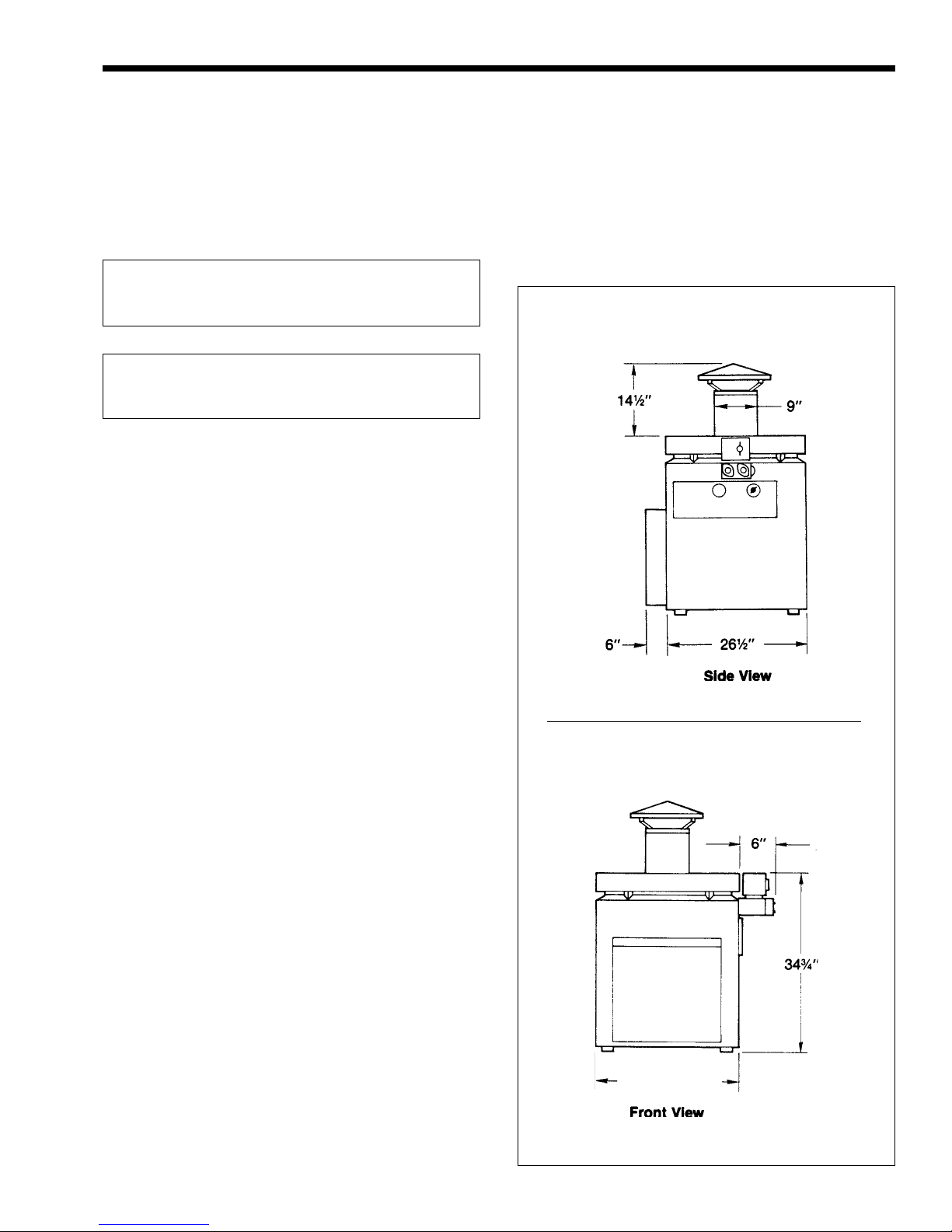
DP-2000: 22½"
DP-3000: 26¾"
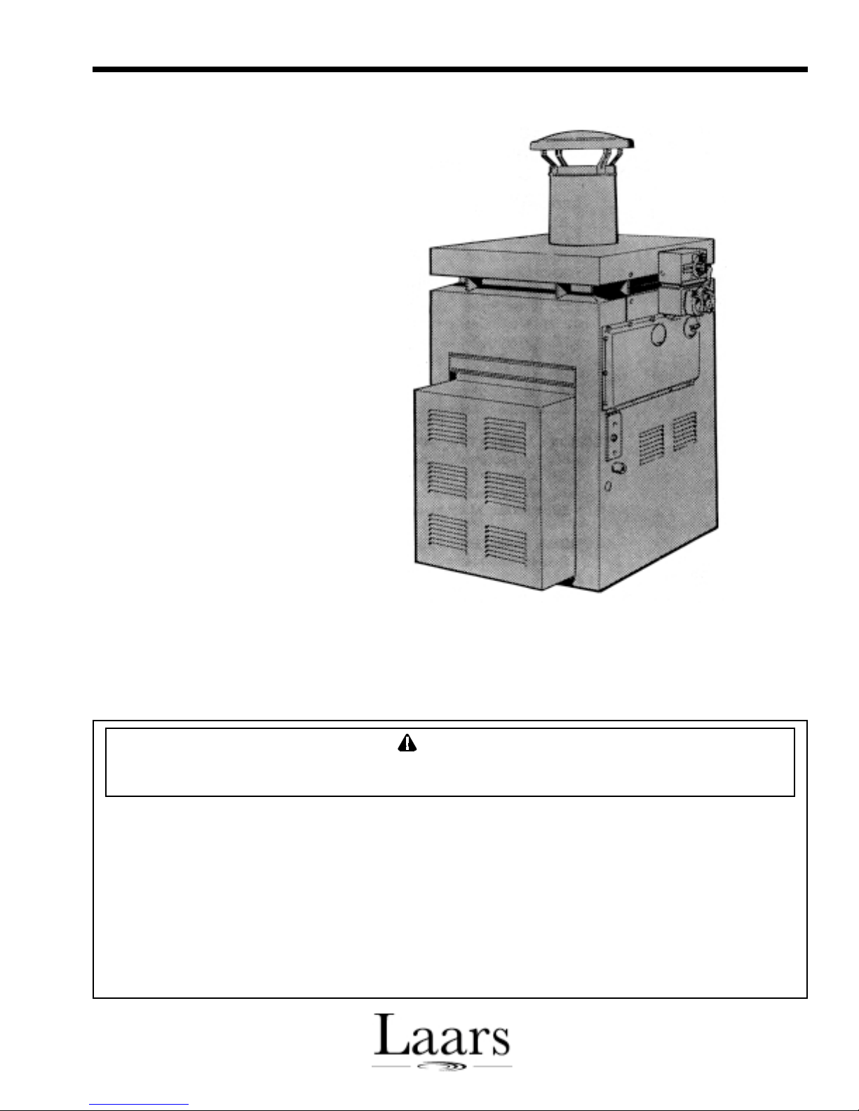
Figure 1. XL-2 Oil-Fired Heater.
Page 4
Figure 2. Non-Combustible Platform. Figure 4. Inner Stack.
pipe. To assemble the inner stack, remove the tape
and small envelope from the sheet metal coil. Expand
the coil until the holes on each end are aligned. Use
the two screws supplied in the small envelope to
secure the ends together. Install the inner stack, 7"
(18cm) diameter, on the collar of the flue collector
before attaching the vent cap (outdoor installation) or
vent pipe (indoor installation) as shown in Fig. 4. The
XL-3 can be installed with the water connections on
either side. Water Pik Technologies ships the heater
with the water connections on the right side, but
changing the connections to the left side could simplify
the installation or improve access for service and
maintenance. Make the change before locating and
connecting the heater.
Follow these step-by-step instructions and
Figure 3 to reverse the heat exchanger:
Figure 3. Heat Exchanger Reversal.
1. Remove the control compartment door.
2. Remove the chimney cap assembly, or
barometric draft control if one is installed, and the
inner stack (1).
3. Remove the eight screws securing the top
assembly (2) and lift off.
4. Bend back retaining tabs and lift out the
wire guard (3). Take off the four V-baffles
(2 each side).
5. Lift out the flue collector assembly (4).
6. Remove the siphon loop cover (5) located on the
right side of the heater under the In-Out header.
7. Remove both gap spacers (6).
8. Disconnect the siphon loop on the header (7).
Remove both drain cocks (8) (one at each end of
the heat exchanger).
Model DP Oil-Fired Heater
9. Lift off both heat exchanger baffles.
10. Carefully remove the insulation at each corner of
the heat exchanger; it will be re-used. Remove the
four hold-down screws (10).
11. Unplug the electrical connector at the switch box
inside the control compartment. At the other end
of the conduit, loosen the brass compression
fitting one or two turns. Rotate the conduit
assembly and lay it on top of the heat exchanger.
FOR YOUR SAFETY: It is recommended that
two people perform the next step.
Page 5
12. Lift out and rotate the heat exchanger. Make sure
the insulation strips stay in position under the
header bars.
13. Put the screws through the hold-down clips at
each corner of the heat exchanger. Put the
insulation back in the corners.
14. Rotate the conduit assembly and attach it to the
switch box. Tighten the compression nut on the
other end.
15. Replace the heat exchanger baffles and the flue
collector assembly.
16. Install the drain cocks and pipe plug according to
the illustration (see Fig. 5).
17. Straighten the siphon loop tubing and connect it to
the header where the drain plug was removed.
18. Replace the gap spacers, siphon loop cover and
rubber plugs and grommets.
19. Install the T-baffles on the gap spacers to match
the screw holes in the top assembly.
20. Replace the wire guard. Bend the tabs to secure it
in place.
21. Attach the top assembly. Install the inner stack
Figure 6. Minimum Clearances, Outdoor Installation.
22. Install the chimney cap assembly, or barometric
draft control if one was removed.
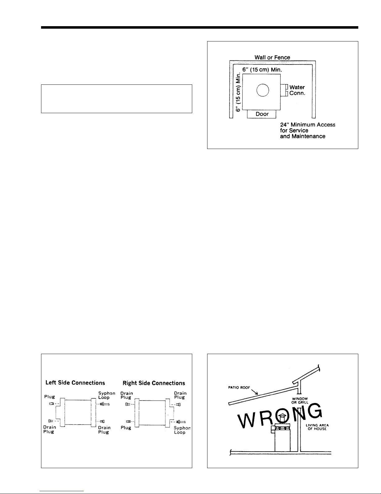
2C. Outdoor Installation
Install the Laars XL-3 heater in the open, or in an
enclosure without a roof. The chimney cap supplied
with the heater must be installed. The danger of fire
requires a minimum clearance from combustible
surfaces or shrubbery of 6 inches (15cm) (see Fig. 6).
The flue products must be dispersed in the outside air,
and fresh air available for proper combustion. Do not
install the heater under eaves where roof drainage
could fall directly on the heater.
It is possible that prevailing winds could cause a
downdraft. Therefore, keep the side of the heater at
least 3 feet (91 cm) from the face of any wall or fence.
2D. Indoor Installation
2D-1. Venting
If the heater is installed in an occupied building,
Figure 5. Connection Locations.
Figure 7. Incorrect Installation.
Page 6
Figure 8. Venting, Indoor Installation.
the room containing the heater must have its own
combustion and ventilation openings as described
below (see Fig. 8).
Vent the XL-3 to a permanent chimney or
through the roof with an approved stack when it is
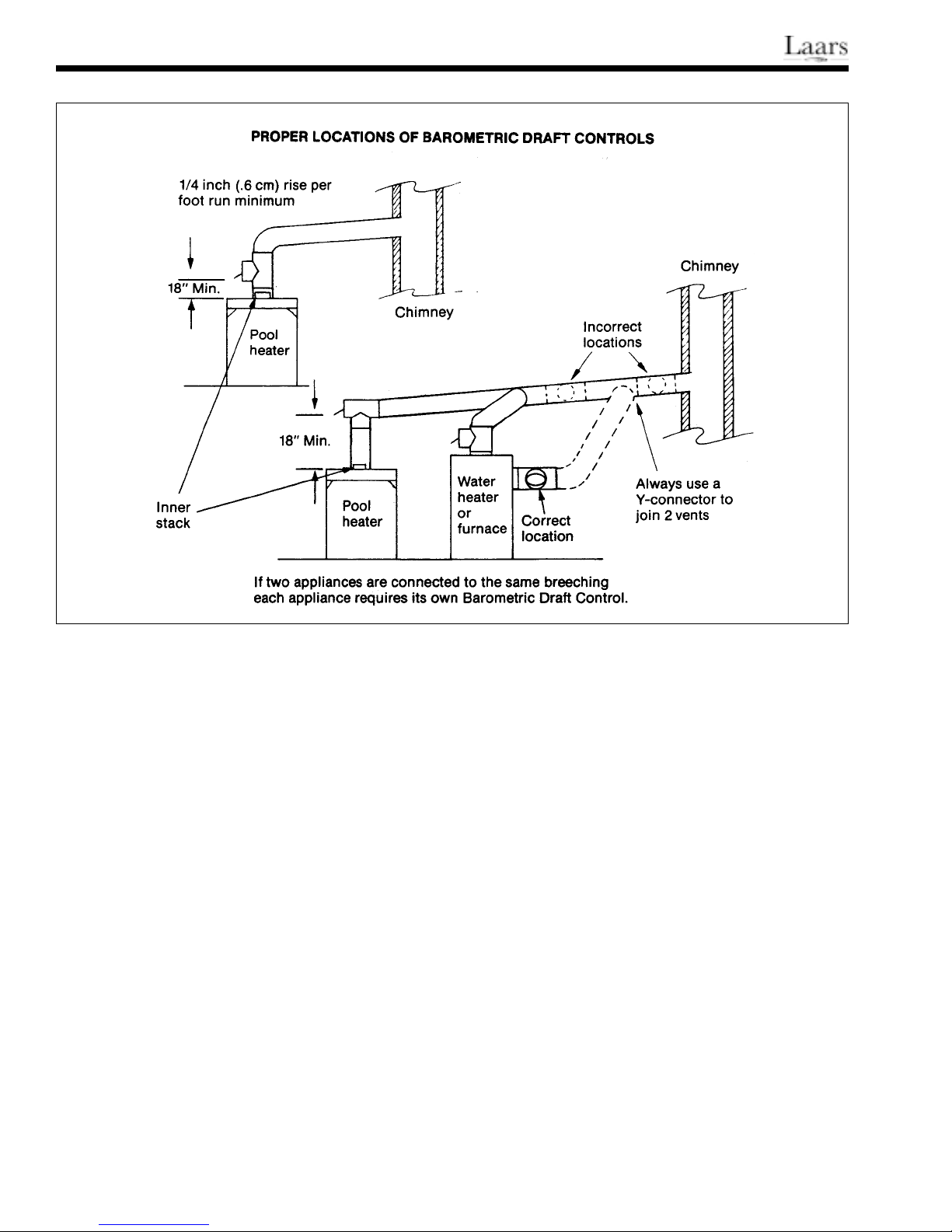
installed indoors. You must install a barometric draft
control between the heater and the stack with a
minimum 13" clearance between the chimney
connector and any combustible surface. Observe
NFPA Standard No. 31 and all national and local
ordinances.
Run the vent pipe as directly as possible with
minimum turns. Never use a vent smaller than 9"
(23cm). On lateral runs, maintain a minimum pitch of
1/4" (.6cm) per linear foot. If a chimney is used, the
total equivalent straight length of flue piping between
the heater and the chimney should not exceed 75% of
the vertical height of the chimney above the flue pipe
connection. The chimney should be at least 9" (23cm)
diameter. Maintain adequate clearances between the
vent pipe and combustible materials. Check local codes
and the vent manufacturer’s instructions for proper
clearances. The 7" (18cm) dia. inner stack must be in
place.
Any change in the amount of draft in the
combustion chamber can affect the flame
characteristics. An approved barometric draft control
must be used on all indoor installations to maintain a
clean and consistent flame. When the system is
properly adjusted, the pressure in the stack below the
draft control will be approximately minus .03" W.C. If
this draft pressure cannot be achieved, the chimney is
too short or too small. Take corrective action.
Avoid locating the chimney termination in a
location susceptible to down draft conditions, or near
ventilation inlets to the building.
2D-2. Clearances
Provide the following minimum clearances from
combustible surfaces:
Water Inlet/Outlet side 24" (61cm)
Other side and rear 6" (15cm)
Front Control compartment 24" (61cm)
Chimney connector 13" (33cm)
2D-3. Combustion Air Supply
Do not install the heater in a room that does not
have enough air supply to support combustion. There
must be two openings to outside air provided; each
opening must have a free area equal to 80 sq. in.
(516.1 sq. cm). It is good practice to put one opening
near the floor and the other near the ceiling.
When installing the heater in an interior room, all
doors communicating with outside air must have
specified openings (see Fig. 9). There must be no
 Loading...