

Page 1
&)(-)292+7%2;)-792+
QMX1SRXEKIER[IMWYRKIR
-RWXVYGXMSRWJSVYWIERHMRWXEPPEXMSRMRWXVYGXMSRW
-RWXVYGXMSRWHYXMPMWEXMSRIXEZMWHIQSRXEKI
+IFVYMOWEER[MN^MRKIRQSRXEKILERHPIMHMRK
+),
+&
Page 2

^~y
Please read the information in this leaflet carefully. It contains important instructions for the safety, installation, use and maintenance of your appliance.
The appliance is only intended for the preparation of food in the home.
Please keep the operating instructions in a safe place.
The appliance belongs to appliance category 3.
If any changes are made to the appliance and its connection, this will
impair the appliance’s safety and proper functioning in all other countries.
[|~yy}}
The conditions of guarantee applicable for this product are those published
by our representative in the relevant country.
Details regarding these terms of guarantee may be obtained from the dealer
from whom the appliance was purchased. The sales receipt must be
produced when making claims under guarantee.
[}
Your cooker at a glance . . . . . . . . . . . . . 19
Safety instructions. . . . . . . . . . . . . . . . . 20
for connection and functions
for the gas hob
for the oven
Before first use . . . . . . . . . . . . . . . . . . 20
Disposing of the packaging and the old appliance
Initial cleaning
Using the rings. . . . . . . . . . . . . . . . . . . 21
Setting the burners
Notes on the right types of saucepan
The oven . . . . . . . . . . . . . . . . . . . . . . 22
Selecting the operation mode and the temperature
Symbols and operation modes
Thermostat settings
Ignite the oven burner and set the temperature
Shelving options and equipment
Baking
Roasting
GInstalling the grill
Grilling
Preserving
backmobil (special accessory no. 600). . . . . . . . . . 24
Cleaning and caring for the appliance . . . . 25
backmobil
®
Oven
Troubleshooting . . . . . . . . . . . . . . . . . . 26
Nameplate
Installation instructions . . . . . . . . . . . . . 26
Planning the supply lines
Installing the cooker into your fitted kitchen
Installing the glass ceramic gas hob
Installation the hob
Checking the supply lines
Checking the oven burner
Checking the ring burners
Factory setting / conversion possibilities . . . . . 30
Table of permissible types of gas and pressures
Table of injector sets
Conversion injector sets
Table of heat input
Gross calorific values according to EN 437
Resetting the ring burners
Resetting the oven burner
Final assembly
18 GEH 630.0
Page 3
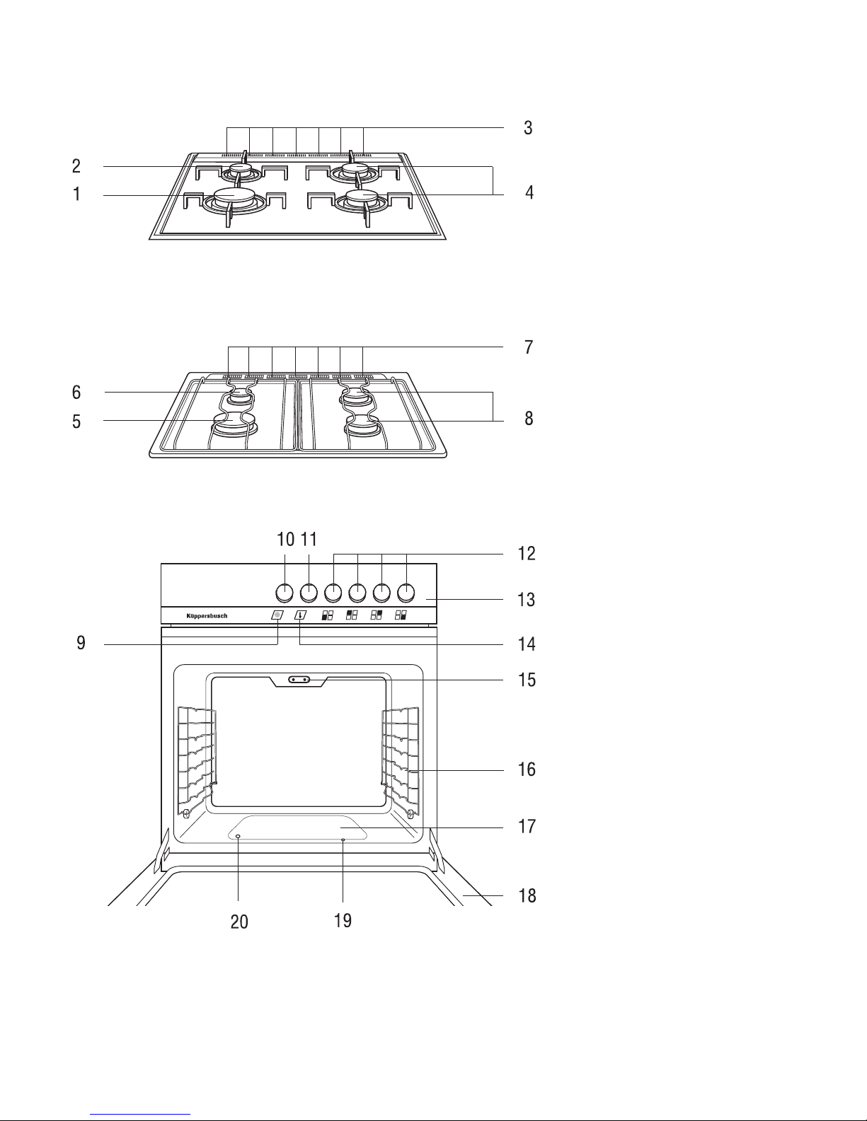
q{}yyy{}
1 High speed ring
2 Simmering ring
3 Ventilation slits
4 Standard ring
5 High speed ring
6 Simmering ring
7 Ventilation slits
8 Standard ring
9 Oven function indicator elektro
10 Oven function switch
11 Oven temperature switch
12 Cooking zone regulator
13 Control panel
14 Oven function indicator-gas
15 Grill connector
16 Side grids
17 Cover plate for oven burner
18 Oven door
19 Auxiliary ignition hole
20 Viewing hole
Available accessories:
Ring for small pots acc. no. 160
Roasting grid acc.-no. 440
Roasting tray acc.-no. 441
Drip pan acc.-no. 543
Baking tray, alu acc.-no. 542
backmobil
acc.-no. 600
GEH 630.0 19
Page 4
ky~}{
for connection and functions
Before the appliance is installed, it must be checked whether the local
supply conditions (type of gas and gas pressure) and the settings of the
appliance correspond. All settings for the appliance are stated in this
user guide. This appliance should not be connected to a pipe for extracting
combustion products. It must be fitted and connected in accordance with
the applicable conditions of installation. Particular attention should be
paid to suitable ventilation measures. The use of a gas cooker causes
heat and humidity to build up in the room where the cooker is installed. For this reason it should always be ensured that the kitchen is
well ventilated; keep the ventilation slits open or provide for a mechanical ventilation facility (e.g. a cooker hood). If the appliance is subject to
particularly intensive use or use over a long period of time, it might be
necessary to provide for additional ventilation, e.g. by opening a window or operating a cooker hood at a high power level.
Küppersbusch cookers are made according to the applicable safety
regulations. Only Küpperbusch ovens may be connected to Küpperbusch hobs.
The appliance should only be connected to the gas mains by a qualified gas
fitter. The same applies for all adjustments and conversions. Attention must be
paid to the statutory regulations at all times. It is also necessary to observe
the instructions of the relevant gas board for connecting up the appliance.
The cooker should only be installed in a well ventilated area.
Do not use the cooker for heating rooms.
If problems occur during operation the gas supply should be turned off
immediately.
The appliance should only be serviced and repaired by a qualified technician in accordance with the applicable safety regulations. When repair
jobs are being carried out on any equipment running on gas, it is always
important to turn off the gas supply. Work carried out incorrectly places
your safety at risk.
If the cooker is run on liquefied petroleum gas (propane/ butane) it is vital to
ensure that all joints between the gas bottle and the cooker are secure and tight.
External flexible supply hoses should not be wedged into tight positions
or laid cross hot surfaces.
The surfaces of the oven, oven door and hob are very hot when in
operation. Always keep children away!
Connection leads of electrical appliances should not be placed on the
hot hob or be allowed to become jammed in the hot oven door.
Do not lift the appliance by the handle of the oven door.
We recommend that you have the appliance serviced at regular intervals.
WARNING! This appliance must be earthed!
for the gas hob
Cooker hoods above the hob must be fitted at a minimum distance of 650 mm.
The rings should not be ignited unless you are cooking something.
Always ensure that the burner covers are in the correct position.
Attention: The electronic automatic spark ignition will not work if there is
a power failure! In such cases please use matches.
Overheated fats and oils may spontaneously ignite. Food cooked in fat or
oil, e.g. chipped potatoes, should only be cooked under supervision.
Never extinguish ignited fats and oils with water! Put the lid on the pan,
switch off the ring and remove the pan from the hot hob.
Pressure cookers should be constantly supervised until the correct
pressure has been reached. First turn the burners of the rings up to
maximum flame and then (following the instructions of the manufacturer
of the pressure cooker) turn the heat down in good time.
The ventilation slits in the hob should not be covered over.
If cracks, fractures or any other defects appear in your glass ceramic
hob, immediately switch off the appliance. Disconnect the fuse.
for the oven
When carrying out repairs and replacing oven light bulbs, the cooker
must be disconnected from the mains (switch off the fuse).
Never store any objects in your oven which could cause a hazard if the
oven is unintentionally switched on.
Take special care when working in the hot oven. Use a dish cloth, oven
gloves or similar.
The oven door must close well. In the event of damage to the door sealing, hinges, sealing surfaces or to the glass pane, do not use your cooker until it has been repaired and checked by a qualified and authorised
trained installer.
Caution! When opening and closing the oven door, do not reach into the
hinge. Risk of injury!
Always close the oven door completely when preparing food in the oven.
Keep at least 5 cm away from the grill and top heat
During use, open and shut the oven door with care to prevent the burner flames being extinguished.
The ventilation slots in the hob serve to ventilate the oven and should
not be covered!
Do not spend more than 15 seconds attempting to ignite the oven flame
when the door is closed. If the attempt is unsuccessful after this time
period, open the oven door and ventilate for at least one minute before
trying again.
During use, open and shut the oven door with care to prevent the burner flames from being extinguished.
The ventilation slots in the hob serve to ventilate the oven and should
not be covered!
Z}~}~}
Disposing of the packaging and the old appliance
Dispose of the transport packaging in such a way that is not harmful to the
environment.
If the appliance is purchased in Germany the dealer who sold you the appliance will dispose of the transport packaging for you.
Recycling the packaging saves raw materials and reduces the amount of waste disposed appliances still contain useful materials. Dispose of your old appliance at a collection point for recycling useful materials.
Before disposing of your old appliance ensure that it cannot be used any
longer. This will prevent misuse.
Initial Cleaning
Remove excess materials and packaging. Before preparing food for the first
time, the cooker must be cleaned.
Clean the glass ceramic cooking area or hob, baking trays, drip pan etc.
with a damp cloth and a little detergent.
Heating the hob (not for glass ceramic hobs)
Consecutively heat up the hotplates for 5 minutes each at the highest setting. Air the kitchen well because of the “new smell”.
Heating the oven
Close the oven door.
Heat up the oven with bottom heat at maximum temperature for 60 minutes.
Air the kitchen well at the same time.
20 GEH 630.0
Page 5
m}
Take note of the safety instructions on page 20!
Switching the cooking zones on and off
Each cooking zone has its own regulator, which can be pushed down.
The symbols on the control panel indicate which regulator operates which
cooking zone.
The cooking zone burners are ignited by an electric spark.
They can also be lit with matches or something similar (e. g. in the event of
power failure).
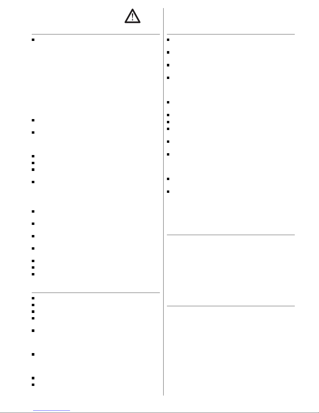
Igniting the cooking zone burners:
- Release the depressed cooking zone
regulator by pressing down.
- Turn the regulator anti-clockwise to
the high position and press in halfway, until a resistance can be felt.
The flame has been ignited.
- Keep the cooking zone regulator
down for another 5-10 seconds and
press in firmly once more, before releasing. The flame is now burning.
- If at any time the flame does not light successfully, allow about two seconds and repeat the procedure. Press the control knob in slightly longer
and possibly a little bit more firmly.
Adjusting the setting:
The maximum and minimum settings are marked on the cooking zone regulators. The flame can be regulated directly.
- Bring to the boil at a high setting if
possible and continue simmering at
a low setting.
Switching off the cooking zone burners:
- Turn the cooking zone regulator clockwise to zero setting.
All cooking zone burners are protected thermoelectrically. If at any time the
flame is extinguished unintentionally (e. g. due to pans boiling over or due
to a strong draught), the gas supply switches off automatically.
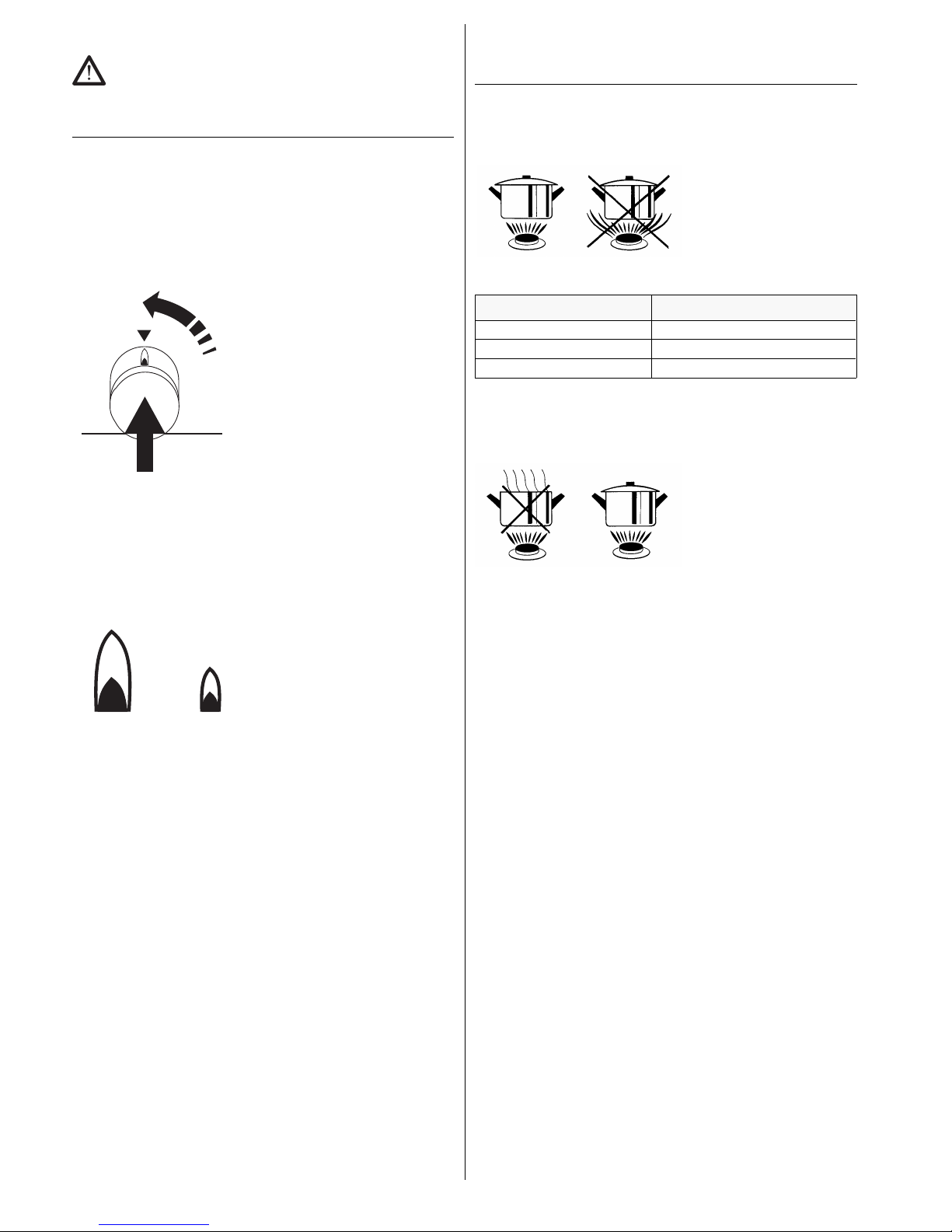
Notes on the right types of saucepan
Using the right types of saucepan will help you to save energy and cut
down on cooking times.
Make sure that the diameter of the saucepan base fits the ring.
Place the saucepan onto the
ring so that the two fit correctly.
The flame should completely
cover the area at the bottom of
the saucepan, but should not
burn round it at the sides.
Ring Diameter of saucepan base
High-speed ring (2.8 kW) 240 - 260 mm
Standard ring (1.9 kW) 200 - 220 mm
Simmering ring* (1.1 kW) approx. 120 mm
* Small pots can also be used using the small pot ring only on the highspeed ring (acc. No. 160).
Always make sure that the lid is on the saucepan.
The food will only boil over if the
flame is set too high. With a
little practice you will learn to
set the flame to just the right
heat so that the food will not
boil over, even when the lid is
on the saucepan.
GEH 630.0 21
Page 6

l}}
Please note the safety instructions on page 20!
Selecting the operation mode and the temperature
Selecting the operation mode:
with the oven function (the switch on
the left).
Ignite the oven burner and set the
temperature:
with the temperature selection switch (the
2nd switch from the left).
The oven function indicator-electric on the control panel is illuminated when
a function has been selected.
The oven function indicator-gas on the control panel is illuminated when the
oven burner has ignited and goes off about 20 seconds after the burner
has been switched off. Selecting the operation mode and the temperature
Symbols and operation modes
0 Off
!
Lighting Must always be set for conventional heating.
The Electricity-On lamp will light up in the
operation fascia.
$
Top and bottom heat Baking on one level.
*
Grill Especially suitable for small portions of grilling
food.
Thermostat settings
Temperature Upper/lower heat
in °C suitable for
260-280 Browning
240 Baking
220 Baking, Roasting
200 Baking, Roasting
180 Baking, Roasting
160 Preserving
140 Honeycake
Ignite the oven burner and set the temperature
The oven burner can be ignited when the oven is either open or closed.
The oven burner is ignited by an electric spark.
It can also be lit using a match or something similar at the auxiliary lighting
port (B) (e. g. in the event of power failure).
- Release the depressed temperature
regulator by pressing down.
- Turn the regulator anti-clockwise to
280 °C and press in halfway, until a
resistance can be felt. The flame
has been ignited.
- Hold the temperature regulator down
for another five seconds until the
oven function indicator-gas is illuminated.
- Press in the temperature regulator
firmly once more, before releasing.
The flame is now burning.
- Reset the temperature regulator to
the desired temperature. The oven
burner continues at maximum setting until the selected temperature
has been reached.
If at any time the flame does not light successfully, open the oven door and
ventilate, then ignite once more.
Shelving options and equipment
The oven has grids on both sides each with 8 shelf levels. They form the levels 0 to 7.
The level heights are counted from the bottom upwards (see diagram).
On shelving rail 0 a baking tray with
pizza or the rack with stone pizza slab
can be inserted.
Depending on their use, the rack, the
fat-pan or the baking tray can be inserted on shelving rails 1 to 7.
Instructions regarding the shelving levels can be found with their relevant
uses and in the guideline value tables.
Do not cover the oven floor with aluminium foil and do not place the baking
tray directly on the oven floor. The resulting build-up of heat will impair the
baking or roasting results and will damage the enamel.
Gridirons:
Please make sure that the lock-in position of the gridirons
always faces the front (towards you).
22 GEH 630.0
Page 7

Backing
Set Top Heat / Bottom Heat.
Baking tins
Always place these on the middle of the roasting rack. They should not project out beyond the edge of the rack.
Always place rectangular baking tins onto the rack in a horizontal position.
For baking always use light-coloured baking tins.
Baking trays
Always lift slightly on removing.
After sliding them back into the oven, please ensure that the sloping edge
of the trays are pointing towards the oven door. Always push the baking
trays in as far as they will go.
In operation mode, Top Heat / Bottom Heat, always only work on one rack level.
Use a drip pan for roasting.
Type of cake or
biscuit
Top Heat/
Bottom Heat
Time
Shelf Temperature
in °C
in min
Rich cake dough
Large round cake 2 180-190 50-65
Loaf-shaped cake 2 180-190 50-65
Madeira cake 2 180-190 60-70
Flan 2 180-200 45-65
Flan base 2 180-200 25-35
Fine fruit flan 2 180-190 45-60
Small cakes 2 180-200 15-25
Cake baked on
baking tray:
Dry topping 2 180-200 20-35
Moist topping 2 180-200 50-65
Short pastry
Flan base 2 190-210 25-35
Cheesecake 2 180-200 70-100
Small cakes 2 180-200 15-20
Cake baked on
baking tray:
Dry topping 2 190-210 25-35
Moist topping 2 190-210 30-60
Yeast dough
Large round cake 2 180-200 45-60
Plaited bun 2 180-200 40-50
Christmas cake (preheat) 2 180-190 40-65
Small cakes 2 180-220 15-25
Cake baked on baking
tray:
Dry topping 2 190-210 20-35
Moist topping 2 190-210 50-70
Spongecake dough
Gateaux cake 2 180-200 30-40
Rolls 2 190-200 15-25
Egg-white dough
Meringues 2 140-150 80-90
Cinnamon stars 2 140-150 20-45
Macaroons 2 140-150 20-45
Puff pastry
Puff pastry 2 200-220 15-30
Yeast puff pastry 2 200-225 30-45
Curd cheese puff pastry 2 200-225 30-45
Shortcrust pastry 2 220-240 30-40
Curd cheese oil dough 2 200-210 20-50
Honey cake 2 175-190 20-35
Rye bread 2 200-220 50-60
Roasting
Roasting grid on second shelf from below for meat or drip pan with roasting
tray on first shelf.
The roasting time depends on the type and thicknes of the meat. Raise the
meat slightly when measuring the thickness, as it sinks in a little under its own
weight. The roasting time for meat with a fatty layer can be as much as double.
Dish
Top Heat/
Bottom Heat
Time
Temperature
in °C
time per cm meat
thickness in min
Beef 180-220 18
Roast beef 220-240 10-12
Fillet 220-240 8
Veal 180-220 12
Pork 180-220 12-15
Smoked pork loin 180-220 8
Game 180-220 15
Wild boar 180-220 15
Fillet of game 220-240 8-10
Mutton 180-220 15
Duck 180-200 12
Goose 180-200 12
Chicken 180-200 8
Turkey 180-200 12
Fish 200-220 8
GEH 630.0 23
Page 8

GInstalling the grill
To use the grill you need the plug-in grill accessory no. 540.
Remove the dummy plug from the
back wall of the oven.
Now insert the grill into the grill socket.
Grilling (with accessory no. 540)
Set the heating mode
* to grill.
The oven temperature regulator remains on setting 0.
The oven function indicator-electric on
the control panel is illuminated
- Keep the oven door closed when grilling.
- Preheat the oven for 5 to 10 minutes.
- Insert the drip pan with roasting tray (accessory) in the first shelf
from the bottom, or roasting grid in the shelf level indicated in the table.
Dish Grill
Shelf level 1st side
in min.
2nd side
in min.
Pork chop/-schnitzel 3 8-10 6-8
Pork fillet 3 10-12 8-10
Frying sausage 3 8-10 6-8
Shaschlik 3 7-8 5-6
Meat balls 3 8-10 6-8
Fillet steak 4 6-7 5-6
Liver slices 4 3-4 2-3
Veal schnitzel 3 5-7 4-5
Veal steak 3 6-8 4-6
Mutton chop 3 8-10 6-8
Lamb chop 3 8-10 6-8
Half a chicken
(500 g each)
2 10-12 5-7
Fish fillet 4 6-7 4-5
Trout
(200 – 250 g each)
3 4-7 3-6
Toast 4 2-3 2-3
Topped toast snacks 3 6-8
Preserving
Only use fresh food, prepare as normally described in recipes. Max. 6 bottling jars of 1-1.5 liters capacity.
Only use jars suitable for bottling, all of the same height and filled with the
same contents. The jars should not tough each other.
Fruits
- Insert the drip pan (accessory) in 1 or 2 from below. Pour around 1
liter of water into the drip pan. Preheat to 200°C.
- Turn the top and bottom heat to
170-190 °C .
Keep an eye on the bottling process.
After 50-60 min., the liquid in the first jars will begin to bubble –
usually in the front right-hand jar first of all.
- Then switch off the oven and allow the jars to stand in the closed
oven for about
20-30 min. (approx. 15 min. for delicate fruit e.g. strawberries).
Vegetables and meat
- When the liquid begins to bubble, turn the oven down to 150 °C and
leave to cook for a further 30-60 min.
- Then switch off the oven and leave the jars to stand for about 30 min. in
the closed oven.
l}zy{z
Ø
The oven can be fitted with a backmobilâ (special accessory No. 600).
The backmobil
®
makes it easier for you to use the oven.
For successful roasting or baking it is important to select the correct shelf
level for baking sheets and gridirons. The backmobil enables you to correctly position the baking sheets and gridirons even before you put them into
the oven.
Caution! The backmobil
®
and the lock can be very hot. Use oven cloths,
oven gloves, pan holders etc.
Gliding the backmobil
®
out of the oven: Press down the lever.
Sliding the backmobil
®
into the oven: Slide in slowly until it locks int
24 GEH 630.0
Page 9

[}yy|{y
Make sure that the appliance and the fascia have cooled down
completely before cleaning!
Usually it is sufficient to clean the oven with a damp cloth and a little
washing-up liquid each time you use it. Wipe dry afterwards.
Do not use any abrasive or aggressive cleaning or scouring agents such as steel wool,
soap-impregnated steel wool, metal or plastic sponges or similar agents with an abrasive surface.
Do not use any cleaning agents with a bleaching effect or containing chlorine.
Remove any deposits of calcium or any spots of grease, starch or
egg-white as soon as possible. If this is neglected, corrosion can
develop under these deposits in stainless steel appliances due to
the lack of oxygen.
Food that has boiled over, burnt or become encrusted is best wiped with a damp cloth in the
first instance and then removed. Remove substances from glass ceramic hobs with a glass
scraper. Remove sugar and melted plastic immediately while the hob is still hot.
Clean the glass ceramic hob after every use.
Thoroughly cleanse the glass ceramic hob once a week. A protective
film is formed by thorough cleansing with an appropriate cleansing
agent. It will also make daily cleaning easier. Please note the relevant instructions issued by manufacturers of cleansing agents.
Clean the burner covers and the attachments with hot soapy water.
Take care that attachments and burner covers are replaced correctly after cleaning. Engage burner covers by turning.
backmobil
(special accessory no. 600)
Extending the backmobil
®
Press down the lever at the bottom of
the backmobil
®
frame, extend the
backmobil
®
until it has gone beyond
the catch and lift it diagonally upwards.
Taking the backmobil® apart
Remove the holder rods of the slot-in
gratings first from the front and then
from the back holes on the frame of
the backmobil. The slot-in gratings can
then be removed.
Assembling the backmobil
®
Insert the holder rods of the slot-in gratings back into the holes on the frame
of the backmobil
®
and proceed in the
reverse sequence to the sequence
used when taking the backmobil
®
apart. Push the lever into place.
Oven
From time to time the oven needs to be cleaned thoroughly.
Removing the oven door
Open the oven door as wide as it will
go.
Fold up the clamps on the door hinges.
Take hold of the oven door on the both
sides and close it slowly. When the
oven door is about half-closed, the hinges will fall out of the catches. The
oven door can now be removed.
Loosen the screw to fold down the grill.
Removing the side grating
Loosen the screws.
Remove the slot-in grating.
Reassembling the oven door
Take hold of the oven door on both sides and push the hinges into the relevant holes on the oven.
Very slowly open the oven door.
Fold down the clamps on the door hinges.
Close the oven door.
GEH 630.0 25
Page 10

lz}
Repairs should only be carried out by a qualified technician!
Problem Cause Remedy
Rings will not ignite. Power failure. Check power supply.
Food remains or
cleaning agent between
the spark ignition and
the burner.
Release carefully and clean.
Spark ignition defective. Call Customer Service.
Light with matches in the
meantime.
Flame of burners
suddenly looks
different.
Plug-on rings or tops of
burners are skew.
Shift plug-on rings or tops
of burners until they click
into place.
The cooking ring
control knob suddenly
needs to be held
down longer until the
flame ignites.
Temperature sensor
bent.
Carefully bend the
temperature sensor back
into the correct position.
Plug-on rings or tops of
burners are skew.
Shift plug-on rings or tops
of burners until they click
into the right position.
The oven does not
heat up.
The oven temperature
regulator or the oven
selection switch has not
been set.
Set the oven temperature
regulator or the oven
selection switch.
The flame has gone out. Reignite.
The oven indicator
does not indicate
anything.
Examine the ignition
hole to see whether the
flame is burning.
If so, call After Sales
Service and have the
indicator checked.
It is not possible to
switch off the oven.
Defective electronic
component.
Switch off fuse.
Oven light no longer
works.
Light bulb defective. Call Customer Service to
replace the light bulb.
Glass of oven door is
broken.
Switch off the appliance,
Call Customer Service.
Oven door will not
shut.
Door or door sealing
dirty.
Clean door and sealing
using only warm soapy
water and a damp cloth.
Fruit juice or spots of
egg-white on
enamelled parts.
Moist cake or meat
juices.
Harmless change to the
enamel, no remedy.
Nameplate
is located on the right-hand side strip and is visible when the oven door is
open. Please note the following information for when you contact Customer
Service:
F-number
Model designation oven
Model designation hob
ayy{
Attention!
The appliance category approved for connection can differ from region
to region. If in doubt, ask your local gas board which appliance category
you should use.
Check whether the details on the nameplate correspond to the type of
gas in your area. If not, the hob must be converted to run on the right
type of gas/gas quality!
The appliance should not be connected up or put into operation by
anyone except a qualified gas fitter in accordance with the applicable
regulations.
Küppersbusch built-in ovens should not be installed by anyone except an
authorised fitter and should only be connected up to the corresponding
Küppersbusch built-in hobs.
It is important to adhere to the statutory regulations and installation rules
issued by the local gas board and the local electricity board.
When connecting the appliance or when replacing the oven lamp,
disconnect the appliance from the electricity mains.
It must not be possible to touch the insulated parts of built-in ovens.
The appliance must be protected by a line-protecting cutout, fuses or
contactors with an opening width of at least 3 mm.
The earthing cable must be so long that when the strain relief fails, it is
not subjected to strain until after the live wires of the connection cable.
Planning the supply lines
Threaded appliance joint: R 1/2 “ 150/R 7
Take the following into account when planning the supply lines:
Gas connection with flexible gas safety hose
The joint must be provided with a stop cock and must be accessible.
It is recommended to have a safety gas outlet in the right-hand cabinet.
A flexible gas safety hose, 800 mm in length (as per DIN 3383) is screwed
directly onto the connection points of the hob and screwed on tightly so
that no gas escapes.
If connecting from the left-hand cabinet it is necessary to have a flexible
gas safety hose. Length: max. 1.50 m!
Gas connection to immobile fitting
The joint must be provided with a stop cock and be accessible.
Electrical connection
For the power supply to the oven and the electric automatic spark ignition a
230-240 shockproof socket is required.
The appliance is supplied with a connection cable.
26 GEH 630.0
Page 11

Installing the cooker into your fitted kitchen
Oven cupboards must be temperature resistant to at least 100 °C. This applies especially to veneers, plastic coatings, adhesives and varnishes. Adjacent cabinetry front must be temperature resistant to at least 70 °C. This
film prevents the surfaces from becoming deformed or peeling away, especially on the short sides of the kitchen furniture.
Standard distances in accordance with DIN 68901
Minimum distances between the gas rings and cooker hoods: 650 mm or
according to manufacturer’s instructions.
The back panel and one side of the appliance can be fitted against cupboards
or walls of any height. The furniture on the other side of the appliance,
however, must be flush with the appliance.
It is essential that the appliance
is installed so that it is level.
Preparing the built-in cupboard
In the upper area of the side wall of the cupboard cut out an opening
measuring 100 x 100 mm for the supply lines.
Important: Remopve the back wall of the cupboard and the crossbar
between the side walls, if applicable!
Cutting out the openings in the worktop
The appliance comes supplied with a template for marking out the opening
in the worktop.
Important: Do not mark out the opening in the worktop unless the worktop is already properly fitted.
Place the template against the
front edge of the cabinet.
Mark out the opening for the
cooker in the worktop and cut
out.
Remove transport securing devices.
- The plastic clips used to secure the burner covers during transport are
to be removed from all four burners.
- The burner covers and intermediate rings are to be removed from all
four burners.
- The two front burners are screwed onto housing sheets to secure them
in-transit. Undo the screws.
- The two rear burners are screwed to sheet angles to secure them intransit. Undo the screws. The grating is not needed for the installation of
a glass ceramic hob.
Preparing the gas connection
Check that the details on the nameplate (s. p. 26) are the same as the type of
gas used in your area. If there are any discrepancies, the hob will have to be
converted for the corresponding type or quality of gas (s. p. 30).
Connect the flexible gas safety
hose to the connection points of
the hob and screw on tightly so
that no gas can escape.
Sliding the appliance into place Slide the oven a small way into
the space intended for it in the
cabinet.
Pull the supply lines through the
opening in the side wall. Now slide the oven all the way into its
space. Ensure that the supply lines are not wedged in!
Make absolutely certain that the
hose does not touch any parts of
the appliance which become hot
during cooking!
Fastening in the appliance
Open the oven door.
Using the screws provided and
slanting them outwards, fasten
the appliance to the cabinet.
GEH 630.0 27
Page 12

Readjusting the retractable handles!
After the appliance has been connected and fitted the handles must be
checked to see whether they work in different positions.
If, on account of connecting to the gas supply or fitting into the kitchen
units, the handles no longer work perfectly, the following steps should be taken:
- remove both middle handles
- loosen the screws next to the valve shaft, which are visible through the
handle opening
- using a screwdriver to raise or lower the valve shafts through the handle
opening, align the handle shaft with the centre of the hole and then retighten the screws using a second screwdriver
- replace the handles and check again.
Installing the glass ceramic gas hob
The parts are not assembled when delivered.
The burner tops and plug-on rings are supplied separately.
Assembly is easy, quick and simple owing to the clip method.
- Hammer the clips into the worktop recess at the intervals specified in
the drawing. No height alignment is necessary owing to the horizontal
stop. Should the worktop recess have been made slightly too large, it is
possible to increase the spring tension of the clips by screwing them.
- Attach the separate fume duct on the rear of the worktop recess with
the enclosed screws 4.2 x 16 mm.
- Insert the glass ceramic hob.
Installing the burners
- Raise the burner with the tool
provided and move it into position.
- Screw on the holding sheet
for the burner.
- Assemble the burner.
- Place the burner cover and at-
tachment carefully in the correct position. Turn the cover
to bring into position.
Attachment
Burner
cover
28 GEH 630.0
Page 13

Installation into the hob
- Attach the separate fume duct on the rear of the worktop recess with
the enclosed screws 4.2 x 16 mm.
- Insert the support frame and fasten with screws 4.2 x 16 mm.
- Position the hob loosely.
Raise the burner with the tool provided, position and screw on with three
screws 4.2 x 16 mm and washers in the holes with the thread collar visible.
- Then align the hob and fasten to the appliance with screws 4.2 x 32
mm and washers through the remaining free hole at each burner location.
- Assemble the burner.
- Place the burner cover and at-
tachment carefully in the correct position. Turn the cover
to bring into position.
Checking the supply lines
Power supply
Check the installation of the connection cable. It must not be
tightly wedged in,
pass across the cooker,
be located at a ventilation channel.
Gas supply
Check that all joints are tight and secure.
The hoses must be installed in such a way that they are at a safe
distance from hot surfaces.
The hoses must not be tightly wedged in!
Checking the oven burner
- Ignite the burner and check
that it is burning steadily.
- Heat the oven at the highest
temperature level for at least
10 minutes and then turn it
down to the lowest temperature level. The burner should
burn with a small, but steady
flame.
- If necessary, regulate the air
setting by adjusting the air slide.
The flames should burn steadily, but not as strongly as those of the ring
burners.
Guidelines for the air setting
Natural gas H, E, E+ 3.0 mm
Natural gas L, LL 1,0 mm
Liquified petroleum gas 50 mbar 2.5 mm
Liquified petroleum gas 30/37 mbar * 3.0 mm
Checking the ring burners
Ignite the burner and test the stability of the flame.
The flame should be steady.
GEH 630.0 29
Page 14

^y{}G{}z}
This appliance can be converted to run on other types of gas.
Adjustment and conversion work should only be carried out by a
qualified gas fitter! The applicable rules and regulations should be
observed. Disconnect the appliance from the power supply so that
it is completely free of voltage.
The type of gas and the gas supply pressure must correspond to the
gas setting specified on the appliance.
The factory setting is indicated on an information plate or on
the appliance nameplate.
Table of permissible types of gas and pressures
Table of injector sets
Any subsequent conversions to different types of gas must be
permanently marked on the nameplate of the appliance.
Use only the special injectors which can be ordered from Customer Service.
Country
(ISO country
codes)
Natural
gas H,E
(G 20)
Natural
gas LL
(G 25)
Natural
gas L
(G 25)
Pressure
couple
natural gas
(G 20/25)
Propane
(G 31)
Pressure couple
(Butane/propane)
(G 30/31)
Butane
(Butane/propane)
(G 30)
Category
mbar mbar mbar mbar mbar mbar mbar
Germany (DE) 20 20 50 II
2ELL3B/P
Denmark (DK)
Finland (F)
Sweden (SE)
Iceland (IS)
Norway (NO)
20 28-30 II
2H3B/P
Netherlands (NL) 25
28
50
28-30
II
2L3P
II
2L3B/P
France (FR)
Belgium (BE)
20/25 28-30/37 II
2E+3+
United Kingdom (GB)
Spain (ES)
Italy (IT)
Portugal (PT)
Ireland (IE)
Greece (GR)
20 28-30/37 II
2H3+
Austria (AT) 20 50 II
2H3B/P
Luxembourg (LU) 20 28-30/37 I2E, I
3+
Type of gas,
pressure of gas
High speed ring Standard ring Simmering ring Oven burner
Main injektor Low flame
injektor
Main injektor Low flame
injektor
Main injektor Low flame
injektor
Main injektor Low flame
injektor
Natural gas H, E, E+
G 20 (20/25 mbar)
125569347724115077
Natural gas LL
G 25 (20 mbar)
145 62 117 52 79 47 165 82
Natural gas L
G 25 (25 mbar)
118 61 104 49 78 44 155 80
Liquefied gas butane/propane
G 30(50 mbar)
73 34 62 26 49 23 82 44
Liquefied gas butane/propane
G 30 (28-30/37 mbar
81 39 70 26 53 24 92 52
Liquefied gas propane
G 31 (50 mbar)
79 36 67 30 51 26 89 48
30 GEH 630.0
Page 15

Conversion injector sets
Table of heat input
Total nominal heat input = 11.7 kW
Connected load of the appliance = 843 g/h
Gross calorific values according to EN 437
The HSB calorific value can be obtained from the relevant gas supply company upon installation.
The flow rate is calculated as follows:
flow rate l/min
=
heat input kW x 1000
gross calorific value kWh/m
3
x 60
Resetting the ring burners
Main injectors
If the ring burners are set to run on a different type or quality of gas the
main injector must be replaced.
- Remove the burner cap.
- Through the mixing pipe of the burner mount the socket wrench onto
the injector and unscrew the injector using a screwdriver.
- Place the new injector into the socket wrench and screw it in as far
as it will go.
Low flame injectors
After you have removed the control knobs (for the rings and the oven) and
removed the operation fascia (see below) the low flame injectors can be
adjusted or reset. If you are using natural gas and liquefied petroleum gas
the low flame injectors must be changed. Screw in the injectors as far as
they will go (see Injector Sets table).
- Disconnect the appliance from the
power supply (disconnect the
mains plug).
- Remove the control knobs (for
rings and oven).
- Open the oven door.
Caution: The operation fascia remains connected to the appliance due
to the electrical wiring. It must therefore be handled with care!
- Unscrew the four screws at
the left and right side below
the operating fascia and the
two screws behind the operating fascia.
Lift off the operating fascia,
slightly pull it towards the
front at the lower edge and
carefully remove it towards
the bottom.
- Undo screws, replace low-set-
ting injectors, tighten screws.
Ring Natural gas
20 mbar
25 mbar
Butane/Propane
Input
kW
Input
kW
Gas rate
g/h
Simmering
ring
large 1.1 1.1 79
small 0.3 0.3 22
Standard ring large 1.9 1.9 137
small 0.38 0.38 27
High-speed
ring
large 2.8 2.8 202
small 0.56 0.56 40
Oven burner large 4,0 4,0 203
small 1,0 1,0 72
Gross calorific
values
Calorific value H
s
15 °C
MJ/m3 kWh/m
3
MJ/kg kWh/kg
Natural gas H (G 20) 37,78 10.5
Natural gas L (G 25) 32,49 9.03
Butane (G 30) 49,47 13.75
Propane (G 31) 50,37 14.00
Type of gas,
pressure of gas
Injector sets
Natural gas H, E , E+
G 20 (20/25 mbar)
Natural gas LL
G 25 (20 mbar)
Acc. no. 219
Natural gas L
G 25 (25 mbar)
Liquefied gas butane/propane
G 30 (50 mbar)
Acc. no. 211
Liquefied gas butane/propane
G 30 (28-30/37 mbar)
Acc. no. 218
Liquefied gas propane
G 31 (50 mbar)
socket wrench
main injector
GEH 630.0 31
Page 16

Resetting the oven burner
Main injector
When resetting the oven burner the burner injectors must be replaced.
- Loosen the cover plate.
- Then detach the thermal sensor, the ignition plug, the air slide, the
cover of the casing and the oven burner.
- Set the parts aside and unscrew the burner injector using a socket
wrench of type SW 14.
- Screw in the new injector as shown in the Injector table.
- Reinsert the burner and screw it down tightly.
- Perform the air setting (see above).
Low setting injector
The readjustment is carried out at the oven thermostats. The operation fascia must first be removed.
For natural gas and liquified petroleum gas
Unscrew the injector and replace it by the new injector. Screw in the new injector as far as it will go.
Final installation
Final installation can be carried out after completing the readjustment and
regulation work.
The appliance, built-in according to regulations, is protected on all sides
by a cover, so that it is not possible to touch insulated parts.
The cover can be removed only with tools.
- Mount the operation fascia.
- Mount the knobs for the ring regulators and the oven temperature.
32 GEH 630.0
 Loading...