


VNG4-30024B
Kärcher VNG4-30024B, VNG4-20024B, VNG4-20024A, VNG4-30024A, VNG4-20024H Operator's Manual
...
®
VNG/VLP
Hot Water - Electric Powered - Natural Gas or
LP Heated
Operator’ s Manual
Pressure Washer
MODELS:
VNG4-20024A
1.109-563.0
VNG4-20024B
1.109-564.0
VNG4-20024C
1.109-565.0
VNG4-20024H
1.109-568.0
VNG4-30024A
1.109-569.0
VNG4-30024B
1.109-570.0
VNG4-30024C
1.109-571.0
VNG6-30024B
1.109-575.0
VNG6-30024C
1.109-576.0
VNG8-30024B
1.109-579.0
VNG8-30024C
1.109-580.0
VNG8-30024H
1.109-582.0
VNG10-20024B
1.109-559.0
VNG10-20024C
1.109-560.0
VNG4-30024H
1.109-574.0
For the Landa Dealer nearest
you, consult our web page at
www.landa.com
8.913-939.0-AB 08/22/17
Machine Data Label
2 Landa VNG Operator’s Manual 8.913-939.0 - AB

Table of Contents
Machine Data Label. . . . . . . . . . . . . . . . . . . . . . . . . .2
Table of Contents . . . . . . . . . . . . . . . . . . . . . . . . . . .3
How To Use This Manual . . . . . . . . . . . . . . . . . . . . .4
Safety
Introduction & Safety Information . . . . . . . . . . . . . . .5
Important Safety Information. . . . . . . . . . . . . . . . . . .6
Propane Tank Safety Instructions. . . . . . . . . . . . . . .8
Operations
Component Identification . . . . . . . . . . . . . . . . . . . . .9
Installation. . . . . . . . . . . . . . . . . . . . . . . . . . . . . . . .10
Location . . . . . . . . . . . . . . . . . . . . . . . . . . . . . . . . .10
Gas Codes . . . . . . . . . . . . . . . . . . . . . . . . . . . . . . .10
Electrical . . . . . . . . . . . . . . . . . . . . . . . . . . . . . . . . .10
Gas Piping . . . . . . . . . . . . . . . . . . . . . . . . . . . . . . .10
Union Connection . . . . . . . . . . . . . . . . . . . . . . . . . .10
Pipe Sizing Chart for Natural Gas. . . . . . . . . . . . . .12
LP-Gas (Liquid petroleum gas or propane). . . . . . .12
Filling the LP-Gas Container. . . . . . . . . . . . . . . . . .12
Propane Tank Disposal: . . . . . . . . . . . . . . . . . . . . .12
Combustion and Ventilation Air. . . . . . . . . . . . . . . .13
Water Source . . . . . . . . . . . . . . . . . . . . . . . . . . . . .14
High Pressure Connection . . . . . . . . . . . . . . . . . . .14
Inspection and Testing Gas Piping . . . . . . . . . . . . .14
Gas Pressure . . . . . . . . . . . . . . . . . . . . . . . . . . . . .14
Start Up. . . . . . . . . . . . . . . . . . . . . . . . . . . . . . . . . .15
For Your Safety Read Before Lighting . . . . . . . . . .15
Assembly Instructions. . . . . . . . . . . . . . . . . . . . . . .17
Operating Instructions. . . . . . . . . . . . . . . . . . . . . . .18
Applying Detergent &
General Operating Techniques. . . . . . . . . . . . . .19
Thermal Pump Protection. . . . . . . . . . . . . . . . . . . .19
Rinsing . . . . . . . . . . . . . . . . . . . . . . . . . . . . . . . . . .19
Shutting Down And
Clean Up. . . . . . . . . . . . . . . . . . . . . . . . . . . . . . .20
Storage . . . . . . . . . . . . . . . . . . . . . . . . . . . . . . . . . .20
Spray Nozzles. . . . . . . . . . . . . . . . . . . . . . . . . . . . .21
Unloader Valves . . . . . . . . . . . . . . . . . . . . . . . . . . .21
Winterizing Procedure. . . . . . . . . . . . . . . . . . . . . . .21
High Limit Hot Water Thermostat . . . . . . . . . . . . . .21
Pumps. . . . . . . . . . . . . . . . . . . . . . . . . . . . . . . . . . .21
Factory Set Parameters . . . . . . . . . . . . . . . . . . . . .26
Maintenance Schedule . . . . . . . . . . . . . . . . . . . . . .27
Oil Change Record . . . . . . . . . . . . . . . . . . . . . . . . .27
Troubleshooting - Burner . . . . . . . . . . . . . . . . . . . .28
Troubleshooting . . . . . . . . . . . . . . . . . . . . . . . . . . .30
Parts
Landa - 4-2000, 4-3000 . . . . . . . . . . . . . . . . . . . . 36
Landa - 6-3000, 8-3000, 10-2000. . . . . . . . . . . . . 42
Control Panel . . . . . . . . . . . . . . . . . . . . . . . . . . . . 48
Electrical Box VNG . . . . . . . . . . . . . . . . . . . . . . . . 52
Burner - VNG 6-3000, 8-3000, 10-2000 . . . . . . . . 56
Pump - VNG 4-2000, 4-3000, 6-3000. . . . . . . . . . 58
Pump - VNG 8-3000, 10-2000 . . . . . . . . . . . . . . . 60
Float Tank - VNGS . . . . . . . . . . . . . . . . . . . . . . . . 62
Float Tank - VNGL . . . . . . . . . . . . . . . . . . . . . . . . 63
Hose & Spray Gun . . . . . . . . . . . . . . . . . . . . . . . . 64
Specifications . . . . . . . . . . . . . . . . . . . . . . . . . . . . 66
Burner Specifications . . . . . . . . . . . . . . . . . . . . . . 70
Burner Basic Facts . . . . . . . . . . . . . . . . . . . . . . . . 71
Unloader - MG4000 w/ Microswitch . . . . . . . . . . . 72
VB8 Valve . . . . . . . . . . . . . . . . . . . . . . . . . . . . . . . 76
Pump - LT.2 Series. . . . . . . . . . . . . . . . . . . . . . . . 78
Pump - LX.2 Series . . . . . . . . . . . . . . . . . . . . . . . 80
Maintenance
Heating Coil . . . . . . . . . . . . . . . . . . . . . . . . . . . . . .22
Gas Valve Regulator Adjustment . . . . . . . . . . . . . .22
Pressure Relief Valve . . . . . . . . . . . . . . . . . . . . . . .22
Propane Gas. . . . . . . . . . . . . . . . . . . . . . . . . . . . . .23
Gas Pressure Requirements. . . . . . . . . . . . . . . . . .23
Burner Features . . . . . . . . . . . . . . . . . . . . . . . . . . .23
Care of Main Burner . . . . . . . . . . . . . . . . . . . . . . . .23
Smart Relay Instructions. . . . . . . . . . . . . . . . . . . . .24
Landa VNG Operator’s Manual 8.913-939.0 - AB
3

How To Use This Manual
Model:
Date of Purchase:
Serial Number:
Dealer:
Address:
Phone Number:
Sales Representative:
This manual contains the following sections:
• How to Use This Manual
•Safety
• Operations
• Maintenance
• Parts List
The HOW TO USE THIS MANUAL section will tell you
how to find important information for ordering correct
repair parts.
Parts may be ordered from authorized dealers. When
placing an order for parts, the machine model and
machine serial number are important. Refer to the
MACHINE DATA box which is filled out during the
installation of your machine. The MACHINE DATA box
is located on the inside of the front cover of this manual.
The model and serial number of your machine is
located on the back of the machine.
The SAFETY section contains important information
regarding hazardous or unsafe practices of the
machine. Levels of hazards are identified that could
result in product damage, personal injury, or severe
injury resulting in death.
The OPERAT IONS section is to familiarize the operator
with the operation and function of the machine.
The MAINTENANCE section contains preventive maintenance to keep the machine and its components in
good working condition. They are listed in this general
order:
• Spray Nozzles
• Unloader Valves
• Winterizing Procedure
• High Limit Hot Water Thermostat
• Pumps
•Heating Coil
• Gas Valve Regulator Adjustment
• Propane Gas
• Burner Features
• Smart Relay Instructions
• Preventative Maintenance
• Oil Change Record
• Troubleshooting - Burner
• Troubleshooting
The PARTS LIST section contains assembled parts
illustrations and corresponding parts list. The parts lists
include a number of columns of information:
4
• REF – column refers to the reference number
on the parts illustration.
• PART NO. – column lists the part number for
the part.
• QTY – column lists the quantity of the part used
in that area of the machine.
• DESCRIPTION – column is a brief description
of the part.
• NOTES – column for information not noted by
the other columns.
NOTE: If a service or option kit is installed on your
machine, be sure to keep the KIT INSTRUCTIONS
which came with the kit. It contains replacement parts
numbers needed for ordering future parts.
NOTE: The manual part number is located on the
lower right corner of the front cover.
Landa VNG Operator’s Manual 8.913-939.0 - AB

Introduction & Safety Information
Thank you for purchasing this Pressure Washer. We
reserve the right to make changes at any time
without incurring any obligation.
Owner/User Responsibility:
The owner and/or user must have an understanding of
the manufacturer’s operating instructions and warnings
before using this pressure washer . Warning in formation
should be emphasized and understood. If the operator
is not fluent in English, the manufacturer’s instructions
and warnings shall be read to and discussed with the
operator in the operator’s native language by the
purchaser/owner, making sure that the operator
comprehends its contents.
Owner and/or user must study and maintain for future
reference the manufacturers’ instructions.
The operator must know how to stop the machine
quickly and understand the operation of all controls.
Never permit anyone to operate the engine without
proper instructions.
Safety
SAVE THESE INSTRUCTIONS
This manual should be considered a permanent par t of
the machine and should remain with it if machine is
resold.
When ordering parts, please specify model and
serial number. Use only identical replacement parts.
This machine is to be used only by trained operators.
Landa VNG Operator’s Manual 8.913-939.0 - AB
5
Safety
WARNING
READ OPERATOR’S
MANUAL THOROUGHLY
PRIOR TO USE.
OPERATIONS
SAFETY
MAINTENANCE
KEEP WATER
SPRAY AWAY FROM
ELECTRICAL WIRING.
WARNING
WARNING
RISK OF EXPLOSION:
IF GAS SMELL
PRESENT TURN OFF
SUPPLY
WARNING
USE PROTECTIVE
EYE WEAR
AND CLOTHING
WHEN OPERATING
THIS EQUIPMENT.
CAUTION
HOT DISCHARGE FLUID:
DO NOT TOUCH OR
DIRECT DISCHARGE
STEAM AT PERSONS.
WARNING
RISK OF FIRE.
DO NOT ADD FUEL
WHEN OPERATING
MACHINE.
WARNING
RISK OF INJURY.
HOT SURFACES
CAN CAUSE BURNS
Important Safety Information
WARNING: If you do not follow these instructions
exactly, a fire or explosion may result, causing
property damage, personal injury or loss of life.
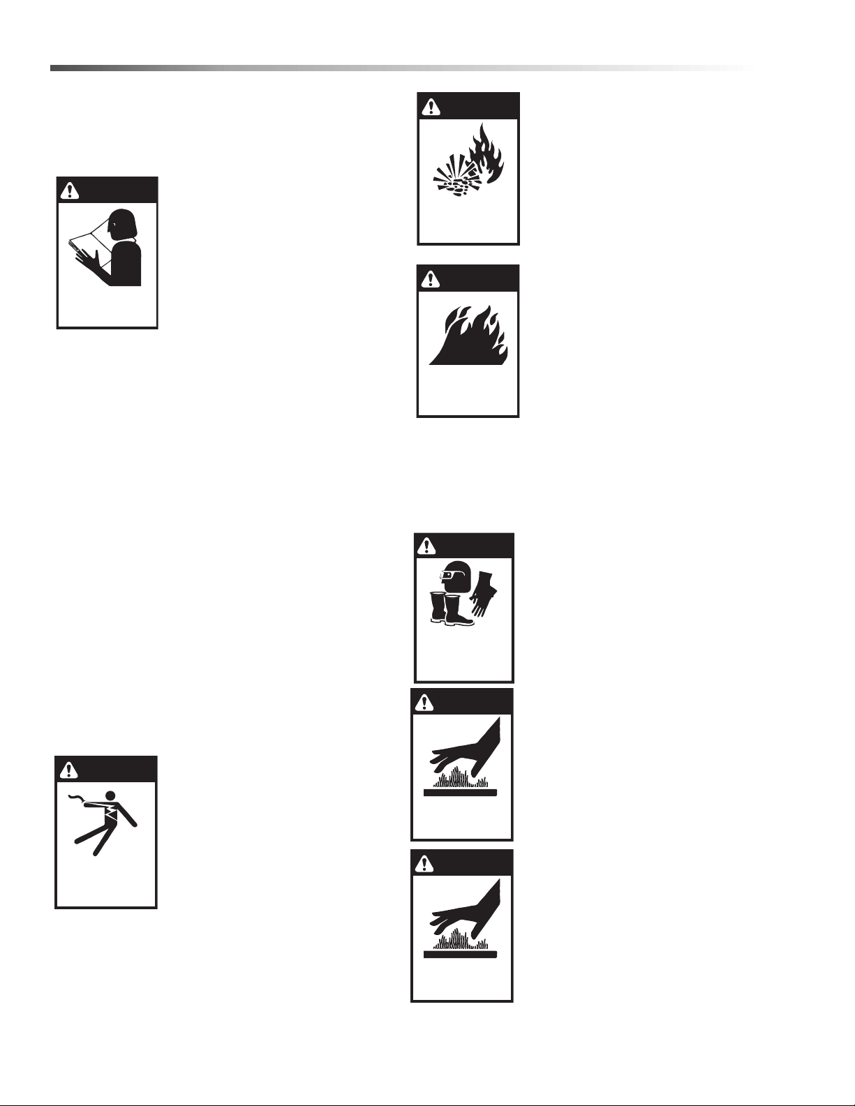
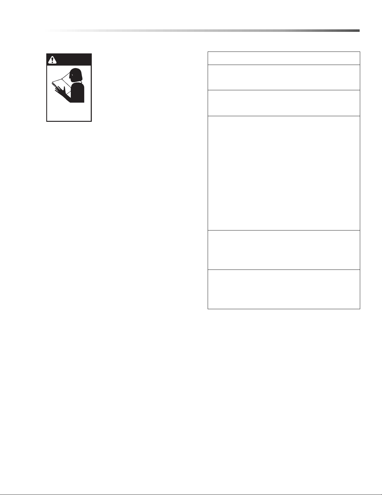
WARNING: To reduce the risk of
injury, read operating instructions carefully before using.
1. Read the owner's manual thoroughly. Failure to follow instructions and warnings could cause
malfunction of the machine and
result in death, serious bodily
injury and/or property damage.
2. Know how to stop the machine and bleed pressure
quickly. Be thoroughly familiar with the controls.
3. Stay alert — watch what you are doing.
4. Use only your hand to push in or turn the gas
control knob. Never use a tool. If the knob will not
push in or turn by hand, don't try to repair it; call a
qualified service technician.
5. All installations must comply with local codes.
Contact your electrician, plumber, utility company
or the selling dealer for specific details. This
product should only be connected to a power
supply protected by a GFCI.
DANGER: Improper connection of the equipmentgrounding conductor can result in a risk of electrocution. Check with a qualified electrician or service
personnel if you are in doubt as to whether the
outlet is properly grounded. Do not modify the plug
provided with the product - if it will not fit the outlet,
have a proper outlet installed by a qualified electrician. Do not use any type of adapter with this
product.
WARNING: Keep wand, hose, and
water spray away from electric
wiring or fatal electric shock may
result.
6. To protect the operator from
electrical shock, the machine
must be electrically grounded. It
is the responsibility of the owner
to connect this machine to a
properly grounded power
supply. Do not spray water on or near electrical
components. Do not touch machine with wet hands
or while standing in water. Always disconnect
power before servicing.
WARNING: Flammable liquids can
create fumes which can ignite,
causing property damage or
severe injury.
WARNING: Risk of explosion —
Operate only where open flame or
torch is permitted. Do not spray
flammable liquids.
WARNING: Risk of fire — Do not
change propane tanks when the
product is operating or still hot.
WARNING: Use vapor fuel only.
7. Gas appliances shall be
installed only in locations where
combustible dusts and
flammable gases or vapors are
not present. Do not store or use
gasoline near this machine.
8. Keep operating area clear of all persons.
WARNING: In the event of a pilot outage, wait at
least five minutes to clear out any gas before
relighting.
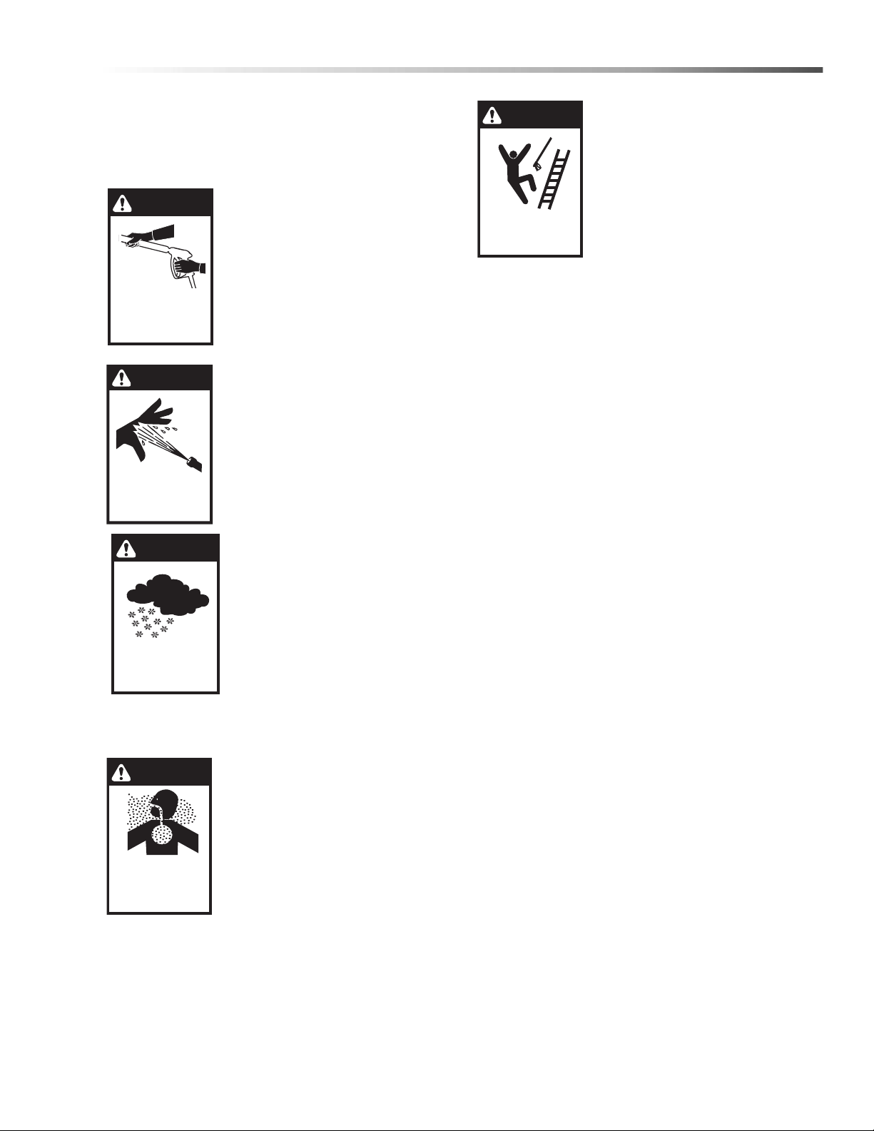
WARNING: High pressure spray
can cause paint chips or other
particles to become airborne and
fly at high speeds. To avoid
personal injury, eye, hand an d foot
safety devices must be worn.
9. Wear properly rated eye protection such as safety goggles or
face shield while spraying.
(Safety glasses do not provide
full protection)
CAUTION: Hot discharge fluid. Do
not touch or direct discharge
stream at persons or animals.
WARNING: This machine produces
hot water and must have insulated
components attached to protect
the operator.
WARNING: Risk of injury. Hot
surfaces can cause burns. Use
only designated gripping areas of
spray gun and wand. Do not place
hands or feet on non-insulated
areas of the pressure washer.
6
Landa VNG Operator’s Manual 8.913-939.0 - AB
Safety
WARNING
TRIGGER GUN KICKS
BACK — HOLD WITH
BOTH HANDS
WARNING
RISK OF INJECTION
OR SEVERE INJURY
TO PERSONS. KEEP
CLEAR OF NOZZLE.
WARNING
PROCTECT FROM
FREEZING
WARNING
RISK OF INJURY
FROM FALLS WHEN
USING LADDER.
DANGER
RISK OF
ASPHYXIATION.
USE THIS PRODUCT
ONLY IN A WELL
VENTILATED AREA.
10. To reduce the risk of injury, close supervision is
necessary when a machine is used near children.
Do not allow children to operate the pressure
washer. This machine must be attended during
operation.
WARNING: Grip cleaning wand
securely with both hands before
starting. Failure to do this could
result in injury from a whipping wand.
11. Never make adjustments on
machine while in operation.
12. Be certain all quick coupler
fittings are secured before using
pressure washer
WARNING: High pressure
developed by these machines will
cause personal injury or
equipment damage. Keep clear of
nozzle. Use caution when operating. Do not direct discharge
stream at people or animals, or
severe injury or death will result.
WARNING: Be extremely careful
when using a ladder, scaffolding
or any other relatively unstable
location. The cleaning area
should have adequate slopes
17. Do not overreach or stand on
unstable support. Keep good
footing and balance at all times.
18. Do not operate this machine
when fatigued or under the
influence of alcohol, prescription medications, or
drugs.
19. Follow the maintenance instructions specified in
the manual.
WARNING: Use vapor fuel only.
20. The LP models are designed to run on vapor
propane fuel. Do not use liquid fuel. Have a
qualified serviceman install and service your equipment.
21. Never expose a spark or flame where there may be
unburned gas present.
WARNING: Protect machine
from freezing.
13. To keep machine in best
operating conditions, it is
important you protect machine
from freezing. Failure to
protect machine from freezing
could cause malfunction of the
machine and result in death,
serious bodily injury, and/or
property damage. Follow storage instructions
specified in this manual.
DANGER: Risk of asphyxiation.
Use this product only in a well
ventilated area.
14. Avoid installing machines in
small areas or near exhaust
fans. Adequate oxygen is
needed for combustion or
dangerous carbon monoxide
will result.
22. Install this machine about 2 feet from wall to
provide adequate ventilation and servicing space.
This equipment incorporates parts such as snap
switches or similar parts that tend to produce arcs
or sparks. Therefore, when located in a garage, it
should be in a room or enclosure provided for the
purpose or should be installed 18" (457mm) or
more above the floor.
WARNING: To reduce the risk of electric shock,
disconnect all electrical connections and shut-off
gas valve before servicing.
23. Install this machine on non combustible flooring.
24. Do not allow acids, caustic or abrasive fluids to
pass through the pump.
25. Never run pump dry or leave spray gun closed
longer than 3 minutes.
15. Manufacturer will not be liable for any changes
made to our standard machines or any components not purchased from us.
16. The best insurance against an accident is precaution and knowledge of the machine.
Landa VNG Operator’s Manual 8.913-939.0 - AB
7
Safety
WARNING
DO NOT SPRAY
MACHINE OR ANY
PEOPLE, ANIMALS OR
ELECTRICAL PARTS.
26. Exhaust gases should not be vented into a wall, a
ceiling or a concealed space of a building. A draft
diverter must be installed to prevent down draft and
to allow cooling of exhaust temperatures. Down
draft diverters shall be
installed in the vents and located at a distance from
the pressure washer stack to achieve maximum
draft of 36" minimum. Exhaust gases that exceed
470°F (243°C) are not suitable for connection to
Type B gas vents.
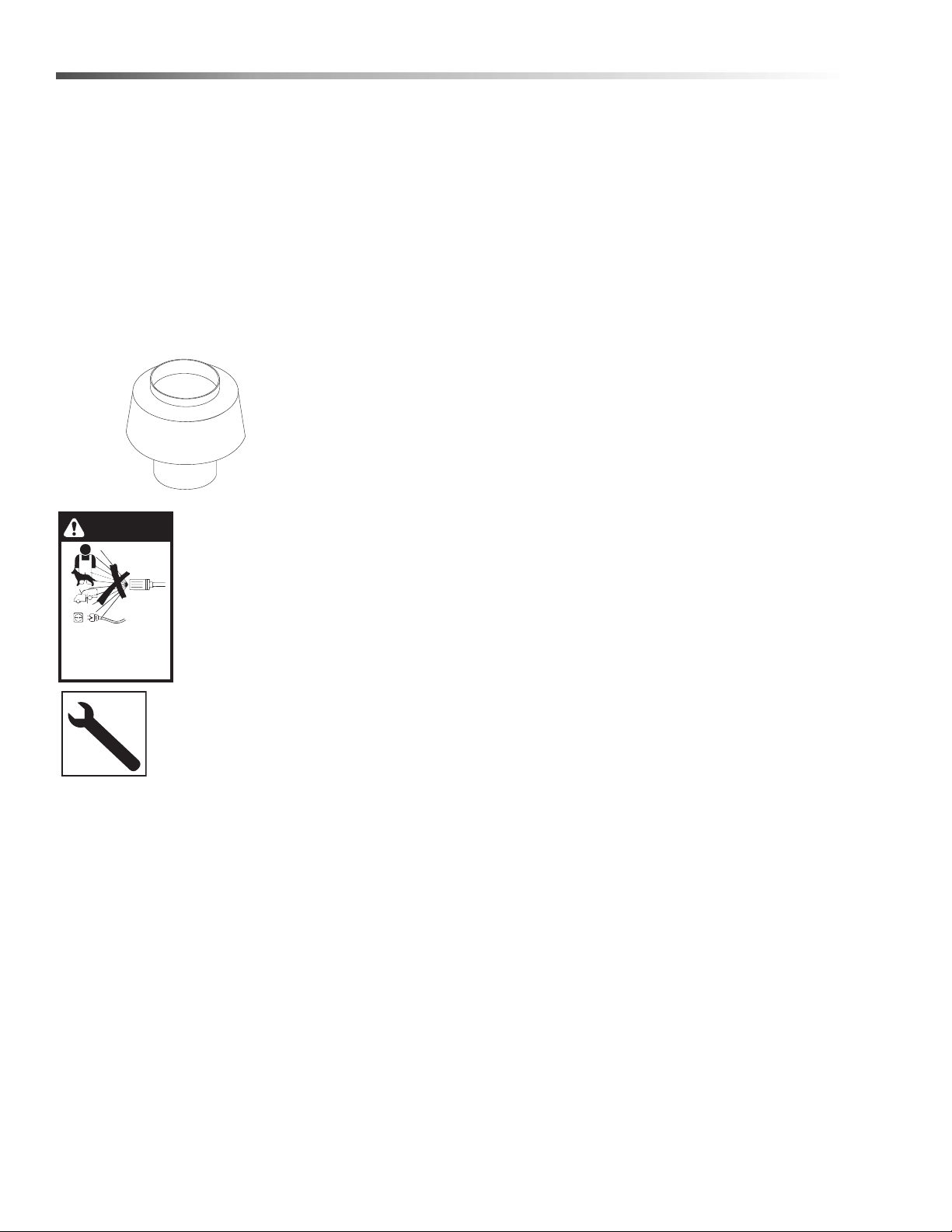
Example of Down Draft Diverter for Gas Fired
Machines
WARNING: Do not spray machine
or any people, animals, or electrical parts.
Follow the maintenance instructions
specified in the manual.
Propane Tank Safety Instructions
CAUTION: Only qualified persons should fill your
LP-gas containers.
1. Never allow your LP-gas container to be filled
above the maximum safe level as indicated by a
scale or the fixed liquid level gauge (outage). Do
not use the visible gauge for filling.
2. Do not use a wrench or pliers to close the service
valve or fixed liquid level gauge. These valves are
designed to be closed leak-tight by hand or screwdriver as appropriate. If wrenches are necessary to
stop a leak, the valve needs repair or replacement.
3. When tightening the POL Nut (left hand thread) on
the service valve, draw it up snug with a proper
wrench. This is a machined male brass fitting
which seats securely against a female seat in the
POL valve – no pipe dope is necessary. Acme/
Type 1 valves have righ t handed threads which are
secure when hand tight, and on the Quick Disconnect/Type 2 Valves, the male connection is
inserted into the female connection on the cylinder
valve. (No wrenches required for both the Acme
and the Quick Disconnect.)
4. When using container, slowly open service valve
all the way. Listen to the regulator. A continuous
hiss may indicate a leak or an open valve on an
appliance.
5. Check all tank and the line connections periodically
to be sure they are tight. When testing for leaks,
use approved leak detector solution – not matches.
6. Make certain your container is properly fastened in
place.
7. Turn container with open part of conta iner guard
towards frame. This protects valves and regulator
against flying rocks and mud. Transport container
in the proper position in which it is used, with the
valves closed and POL Plugs inserted for POL
Valves or Dust Caps for Acme Valves. Secure the
tank against falling or rolling.
8. Check for leaks after connecting. Apply approved
leak detector solution to connection, turn off all
burners and pilots, and open service valve. Leaks
will be detected by the growth of the bubbles. If
bubbles grow, tighten or repair the connection as
needed. Repeat leak test until problem is
corrected.
9. LP-gas is normally non-corrosive – you need not
worry about the inside of your container. However,
the outside should be kept free from rust by a
periodic coat of paint in a light reflective color. It is
very important to inspect and maintain the bottom
and foot ring on the container.
10. Do not store LP-gas containers indoors or in
enclosed areas. Do not expose LP-gas container
to heat. Always store with service valve closed and
plugged as required.
11. Do not attempt to repair any containers, container
valves, regulator or appliances by yourself. Use
only trained certified LP-gas service personnel to
perform repairs.
8
Landa VNG Operator’s Manual 8.913-939.0 - AB
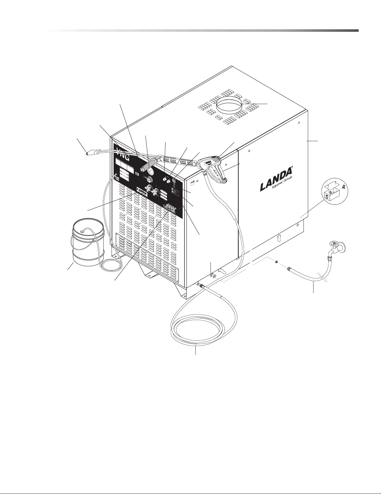
Component Identification
Side Panel
Spray Gun
Draft
Diverter
High Pressure
Nozzle & Coupler
Water Supply Hose
(Not Included)
High Pressure Hose
Variable Pressure
Control Handle
Trigger
Voltage
Light
Pump Light
Pressure
Gauge
Adjustable
Thermostat
Water
Supply
Inlet
Pump
Switch
High
Pressure
Nozzles
Detergent
Bucket
(not included)
Detergent
Valve
Stop
Switch
Hour
Meter
Burner
Switch
Incoming
Power
Electrical Box
Operations
Landa VNG Operator’s Manual 8.913-939.0 - AB
9

Operations
Manual
Shut-Off
Valve
1/8" NPT Plugged Pressure Gauge
Port Location
Union
Drop
Floor Level
Installation
Place machine in a convenient location providing
ample support, drainage and room for maintenance.
Location
The location should protect machine from damaging
environmental conditions, such as wind, rain and
freezing.
1. The machine should be run on a level surface
where it is not readily influenced by outside
sources such as strong winds, freezing temperatures, rain, etc. The machine should be located
considering accessibility for the replacing of
components and the refilling of detergents, adjustments and maintenance. Normal precautions
should be taken by the operator of the machine to
prevent excess moisture from reaching the
machine.
2. It is recommended that a partition be made
between the wash area and machine to prevent
direct spray from the spray gun from coming in
contact with the machine. Excess moisture
reaching the power unit or electrical controls will
reduce the machine’s life and may cause electrical
shorts.
Electrical
The machine, when installed, must be electrically
grounded in accordance to local codes. Check for
proper power supply using a volt meter; check the
serial plate for the correct requirements.
Gas Piping
This machine shall be rigidly connected to the gas
piping outlet and equipped with external manual shutoff valves adjacent to such machine. All gas piping shall
be approved and installed in accordance with the
Uniform Mechanical Code.
Install a gas union in the gas line adjacent to and
upstream from the control manifold and downstream
from the manual main shut-off valve. A 1/8" NPT
plugged tapping accessible for test gauge connection
shall be installed immediately upstream of the gas
supply connection for the purpose of determining the
gas supply pressure to the burner, and to prevent
damage to gas valve.
If a manual gas shut off valve is not in the gas supply
line within six feet of the machine and in an accessible
location, one shall be installed.
Union Location
3. During installation of the machine, beware of
poorly ventilated locations or areas where exhaust
fans may cause an insufficient supply of oxygen.
Sufficient combustion can only be obtained when
there is a sufficient supply of oxygen available for
the amount of fuel being burned. If it is necessary
to install a machine in a poorly ventilated area,
outside fresh air may have to be piped to the
burner and a fan installed to bring the air into the
area.
4. Do not locate near any combustible material. Keep
all flammable material at least 20 feet away.
Allow enough space for servicing the machine.
Local code will require certain distances from
floor and walls. (Two feet away should be adequate).
WARNING: Av oid small areas or near exhaust fa ns.
Gas Codes
Confer with local gas company and with proper
municipal officials regarding any specific code or regulations governing the installation. The installation must
conform to local codes (NFPA 54).
Union Connection
The following pipe sizes are just recommendations.
Always consult a local plumber and venting contra ct or
for local codes and regulations during installation.
10
Landa VNG Operator’s Manual 8.913-939.0 - AB
Operations
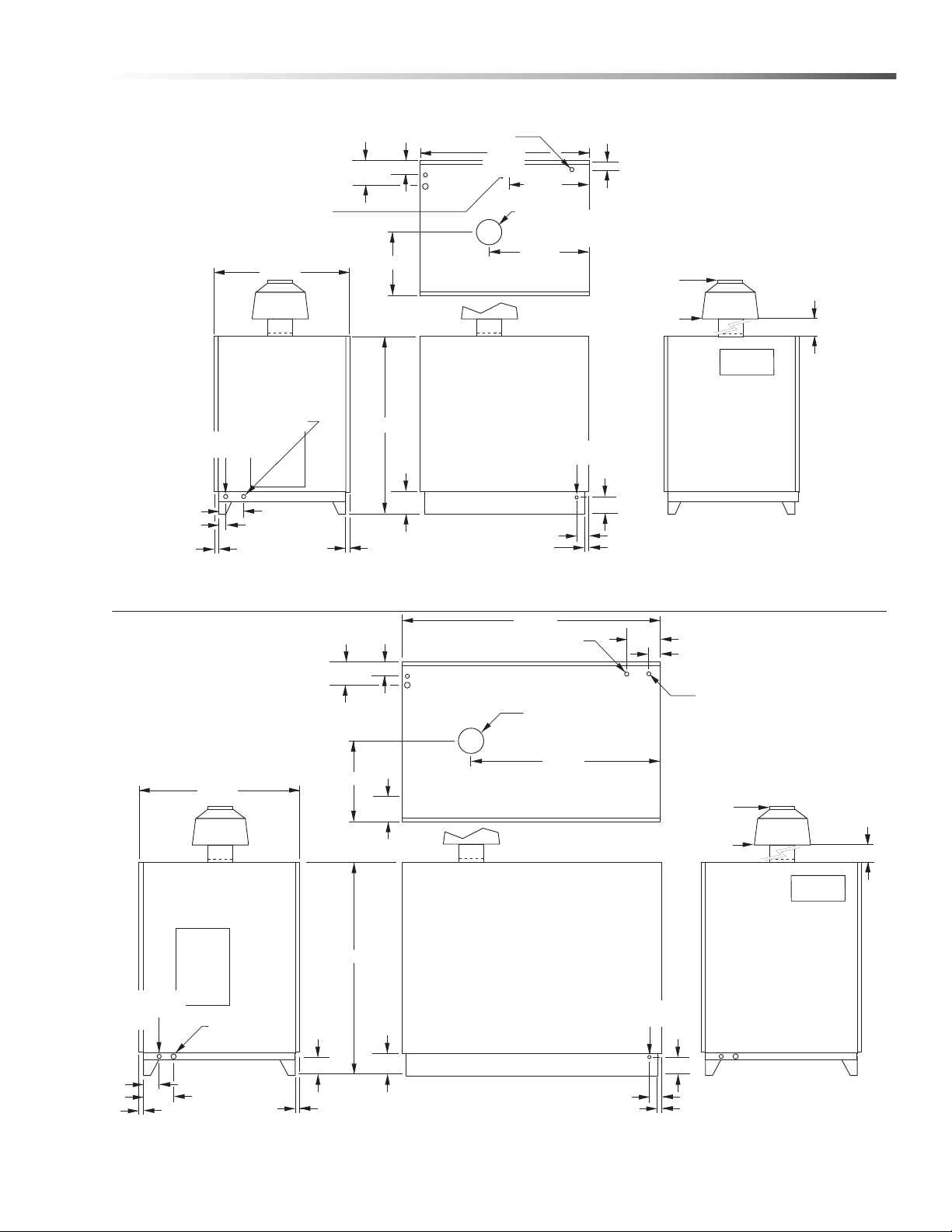
12.00"
2.00"
High Pressure
Out 3/8"
HP Nipple
12.00" Dia.
25.00" Dia.
Control
Panel
Detergent In
5.00"
1.00"
2.00"
1.50"
1.50"
8.75"
5.75"
5.00"
6.00”
57.00"
Gas In
1” NPT-M
Elect. In
3/4 NPT
42.63"
5.75"
21.21"
8.75"
5.00"
Water In 3/4" GHF
69.13"
Electric
Gas
Exhaust Gases
12" Dia.
44.13"
VNG6-3000, 8-3000, 10-2000
18.25"
3.25"
10.00” Dia.
19.50” Dia.
Control
Panel
Detergent In
5.00"
1.00"
2.00"
1.50"
1.50"
2.00"
5.25"
6.00"
47.50"
Gas In
1" NPT-M
Elect. In
3/4 NPT
36.00"
High Pressure Out
3/8" HP Nipple
36.00" Mininum
36.00" Mininum
5.25"
3.50"
Water In 3/4” GHF
Electric
Gas
32.25"
45.00"
Exhaust Gases
10” Dia.
14.50"
VNG4-2000, 4-3000, 4-4000
Landa VNG Operator’s Manual 8.913-939.0 - AB
11

Operations
Length of
Pipe (ft.)
Iron Pipe Size
3/4" 1" 1 -1/4" 1- 1/2" 2"
10 360 680 1400 2100 3950
20 250 465 950 1460 2750
30 200 375 770 1180 2200
40 170 320 660 990 1900
50 151 285 580 900 1680
60 138 260 530 810 1520
70 125 240 490 750 1400
80 118 220 460 690 1300
90 110 205 430 650 1220
100 103 195 400 620 1150
150 84 160 325 500 950
200 72 135 280 430 800
Pipe Sizing Chart for Natural Gas
The following chart is based on gas pressure in the
range 0-0.5 psi, specific gravity of 0.6 and pressure
loss of 0.5" W.C. Numbers are for straight schedule 40
pipe; fittings further reduce capacity. For example, in 1"
size, an elbow is equivalent to about 2.6 feet of pipe
and a tee is equivalent to about 5.2 feet of pipe.
Maximum capacity of pipe in cubic feet/hr of natural
gas (Multiply values by 1000 to get nominal BTU/hr
capacity.
ported, installed and used in the proper position. Do not
transport, install or use a vertical cylinder in a horizontal
or upside down position. Proper care must be taken to
position a horizontal container in the correct position for
vapor withdrawal. Liquid LP-gas could enter the
system designed for vapor only, possibly creating a
hazardous condition.
Always use a POL plug installed on a POL valve or a
dust cap on an ACME/Type 1 valve when transporting
or storing disconnected containers (full or empty).
Check for leaks after connecting. Apply approved leak
detector solution to connection, turn off all burners and
pilots and open service valve. Leaks will be detected by
the growth of bubbles. If bubbles grow , tighten or repair
the connection as needed. Repeat leak test until
problem is corrected.
Check all tank and the line connections periodically to
be sure they are tight. When testing for leaks, use
approved leak detector solution — not matches.
Improved Regulation: The second stage regulator
receives a relatively uniform pressure from the first
stage regulator. This helps the second stage regulator
to maintain appliance pressure at a nearly constant 11"
W.C.
LP-Gas (Liquid petroleum gas or propane)
LP-gas is gas compressed into liquid form for easy
transportation and storage. It is also known as propane
or bottle gas. (Propane tanks are not supplied with this
equipment.)
LP-gas is flammable, is always contained under
pressure and the liquid can freeze skin. Therefore, in
the interest of safety, it is important to understand the
basic facts about LP-gas and LP-gas containers.
Federal DOT (Department of Transportation) regulations require periodic inspections and re-qualifications
of cylinders. DO NOT USE damaged or rusted
containers.
DO NOT store LP-gas containers indoors or in
enclosed areas. Do not expose LP-gas container to
heat. Always store with service valve closed and
plugged as required.
CAUTION: Use LP-gas containers in proper
position.
Most LP-gas pressure washer heaters are designed to
operate on LP-gas vapor only. Therefore, all LP-gas
containers designed for vapor service must be trans-
12
Filling the LP-Gas Container
Only qualified persons should fill your LP-gas
containers.
CAUTION: Overfilling is hazardous!
DO NOT allow your LP-gas container to be overfilled.
Stop filling when liquid appears at the fixed level gauge.
Bleed off excess propane in a safe area. Most LP-gas
containers are equipped with a fixed liquid level gauge
which contacts the liquid level at 80% of container
capacity, allowing 20% for expansion. LP-gas
containers not equipped with a fixed liquid level gau ge
can only be filled by weight.
In cold climates, in order to keep vaporization of LP-gas
at the highest level, keep the fuel levels above 50%.
Propane Tank Disposal:
Propane tanks present a real danger in the waste
stream, so it is essential to properly dispose of old
tanks so they do not injure you or sanitation workers.
The best way to dispose of unused pro pane tanks is by
calling a propane company to pick it up. Propane tanks
are not picked up by garbage collectors, and improper
disposal is illegal in some areas. If a propane tank is
unfit for service, one should contact a propane
company.
Landa VNG Operator’s Manual 8.913-939.0 - AB
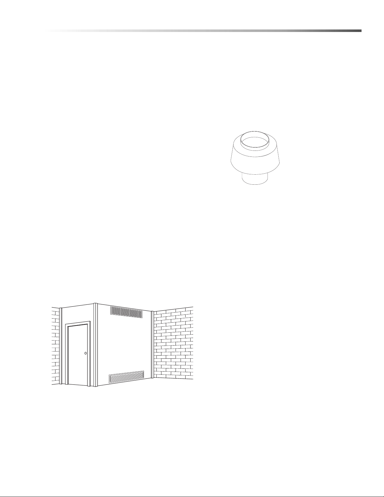
Operations
Draft Diverter
Required
8.717-728.0 8"
9.801-040.0 10"
8.717-730.0 12"
Illustration showing air openings necessary
to supply air for combustion when installed
Combustion and Ventilation Air
Properly sized vents are vital for the safe and efficient
operation of a pressure washer installed in a confin e d
space. When combustion and ventilation air are
supplied from inside the building, each opening must
have an area of one square inch for every 1,000 BTUH
input. When combustion air is supplied from the
outside, each opening must have an area of one
square inch for every 2,000 BTUH for horizontal ducts
and one square inch for every 4,000 BTUH for vertical
ducts (refer to NFPA 54).
The purpose of venting a gas pressure washer is to
completely remove all products of combustion and to
vent gasses to the outside air without condensation in
the vent or spillage at the draft hood (except in cases of
downdraft or poor stack conditions). To assure correct
venting, use a strong, gas-tight insulated pipe with a
cross section equal to that of the flue collar or draft
hood outlet and of sufficient vertical height.
During vent installation, avoid sharp turns, long horizontal runs and improper pitches. Maintain proper
support of vent connectors and joints, observe clearances from all combustibles and top the vent outlet with
an approved cap.
Type “B”, due to its temperature rating, can only be
used with natural draft pressure washers. A “B” vent is
designed for exhaust temperatures not to exceed
470°F (245°C).
All venting installations must conform to local codes. In
the absence of local codes, refer to “National Fuel Gas
Code” NFPA 54 and be constr ucted of materials
approved by the Uniform Building Code.
Sampling Port and Rain Cap. An adapter can be
installed between the collar and stack to adjust the
diameter from 10” to 8” or 12” to 10”.
Size the stack according to the following (see also
applicable local and national standards regarding
installation of gas-fired appliances):
• 3.5 to 4.4 gpm 10” Collar 8” Stack
• 4.5 to 5.5 gpm 10” Collar 10” Stack
• 6.3 gpm 12” Collar 10” Stack
• 8 – 10 gpm 12” Collar 12” Stack
Draft Diverter/Hood The draft required to vent
combustion gases is created by the heat inside the
pressure washer coil. A draft diverter helps improve
draft into the stack without pulling more air through the
combustion box and decreasing combustion ef ficiency.
The draft diverter can also help prevent back drafting
that can inhibit combustion. The draft diverter should be
installed a minimum of 36” above the flue collar.
Power Vent (Draft Inducer) If this machine is going to
be installed on a 90° or extended exhaust vent run
length which may restrict air flow it is recommended
that a contractor install a power vent. When a
contractor has found it impossible to vent straight
through the roof power venting is recommended to
help eliminate exhaust restriction of this natural draft
machine. This draft inducer (power vent) must be
installed by a licensed contractor who can calculate
size, operation connections and associated dampeners. Since we are a manufacturer and not a licensed
contractor and as such we are unable to make recommendations for suitable make and model of power
vents and compliance with local building codes.
in an enclosed room.
The pressure washer includes a collar that will mate
with standard HVAC ducting. The user will be responsible for installation of an exhaust stack. The exhaust
stack should include a Draft Diverter/Inducer, Damper,
Landa VNG Operator’s Manual 8.913-939.0 - AB
Damper An exhaust stack can reduce thermal efficiency by drawing in too much combustion air . This can
be controlled by adding a damper just below the draft
diverter. 8.753-473.0 - 8" Damper, 8.753-474.0 -10"
Damper, 8.753-418.0 - 12" Damper.
NOTE: Closing the damper can create high levels of
CO in the exhaust. Adjustments to the damper should
only be performed by a trained technician using a flue
gas analyzer. If an analyzer is not used the damper
should be set in the fully open position.
13

Operations
Sampling Port A port for sampling flue gases and
measuring the flue gas temperatur e sho u ld be placed
18” above the flue collar. The port should be covered
when sampling is not being performed. The size of the
port should be only slightly larger than the probe for the
flue gas analyzer.
Rain Cap A rain cap should be installed on top of the
stack to prevent rain water, leaves and debris from
entering the stack. Your installer may also recommend
specialty caps for high wind areas or cold weather
zones to help prevent back drafting. 8.717-731.0 - 10"
Raincap, 8.717-732.0 - 12" Raincap
Vents penetrating ceilings or walls should be doublewall approved appliance vents and should be one to
two inches from combustibles. Vents passing through
enclosed spaces and vents exposed to the weather
should also be the double-wall type. Sometimes vents
have to be built of such great length that they come
apart at their joints under their own weight. These
should be screwed together at the joints with sheet
metal screws, usually three per joint. If the inspector
indicates that the vent is too close to combustibles, it
may be necessary to chisel away some of the combustible or route the vent pipe around the combustible. The
cross-sectional area of any flue shall not be less that
the cross-sectional area of the flue vent connection
outlet of machine.
Water Source
The water source for the machine should be supplied
by a 5/8" I.D. garden hose with a city water pressure of
not less than 30 PSI. If the water supply is inadequate,
or if the garden hose is kinked, the machine will run
very rough and the burner will not fire.
High Pressure Connection
Connect the high pressure hose by pulling the coupler
collar back and then inserting it onto the discharge
nipple. Secure it by pushing the collar forward.
Attach the wand into the spray gun using teflon tape on
the pipe threads to avoid leaks.
Inspection and Testing Gas Piping
The building structure should not be weakened by
installing the gas piping. The piping should not be
supported by other piping, but should be firmly
supported with gas hooks, straps, bands or hangers.
Butt or lap welded pipe should not be run through or in
an air duct or clothes chute.
Before turning gas under pressure into piping, all
openings from which gas can escape should be closed.
Immediately after turning on gas, the system should be
checked for leaks. This can be done by watching the 1/
2 cubic foot test dial for 5 minutes for any movement or
by soaping each pipe connection and watching for
bubbles. If a leak is found, make the necessary repairs
and repeat the above test.
Defective pipes or fittings should be replaced and not
repaired. Never use a flame or fire in any for m to locate
gas leaks — use a soap solution.
After the piping and meter have been checked
completely , purge the system of air. DO NOT bleed the
air inside an enclosed room.
During pressure testing of the system at test pressures
in excess of 1/2 PSIG, the pressure washer and its individual shut-off valve must be disconnected from gas
supply piping system or damage to the gas valve will
occur.
Gas Pressure
The ideal incoming gas pressure is 11 w.c.i (water
column inches). Minimum is 9 w.c.i., maximum is 14
w.c.i. or 1/2 PSIG. The correct operating manifold
pressure for natural gas is 3.5 w.c.i. The operating
manifold pressure for propane gas is 10 w.c.i. By
adjusting the gas valve pressure regulator be tw ee n 3
and 4 w.c.i. a side range can be achieved for natural
gas.
If the desired input rating cannot be obtained within the
above manifold pressure adjusting range, then the next
size larger or smaller burner orifice should be used.
The gas pressure coming out of the regulator and going
to the burner ring has been factory set for elevations of
0 to 2000 ft. Altitudes greater than 2000 ft will require
adjustments to the gas manifold pressures. Consult
your local service dealer for high altitude adjustments.
In Canada, certification for installation at altitudes over
4500 feet above sea level is the jurisdiction of local
authorities. You should not readjust the burner ring gas
pressure. If you replace your gas valve, you will need to
adjust the new valve. Refer to your machine’s specifi-
cation plate for the correct pressure setting. Follow the
installation and adjustment instructions provided with
your replacement valve.
NOTE: Air for combustion and ventilation along with
exhaust flue sizing must conform to methods outlin ed in
current American Standard (ANSI-Z223.1) National
Fuel Gas Code or National Standard of Canada CSA-
149.1 and CSA-149.2 “Installation Code for Gas
Burning Appliances”.
14
Landa VNG Operator’s Manual 8.913-939.0 - AB
Operations
WARNING
READ OPERATOR’S
MANUAL THOROUGHLY
PRIOR TO USE.
OPERATIONS
SAFETY
MAINTENANCE
Start Up
WARNING: Read and follow
instructions carefully when
installing or servicing machine.
Failure to do so may result in
damage to property or personal
injury.
1. Installation or servicing of gas
appliances and controls must
only be performed by qualified
personnel. After installation or
servicing, test the manual valve, operating valves,
pressure regulation, and automatic shut-off valve
for proper operation.
2. Install in a suitable dry location. Machine must be
located in an area properly protected from weather.
3. Shut off gas and electricity before starting installation or service. Turn back on to test or operate.
4. DO NOT connect machine before pressure testing
the gas piping. Damage to gas valve may result.
(9" - 14" W.C.P. or 1/2 PSIG)
5. DO NOT insert any object other than suitable pipe
or tubing in the inlet or outlet of the gas valve.
Internal damage may occur and result in a
hazardous condition.
6. DO NOT short the gas valve terminals.
7. DO NOT grip gas valve body with a pipe wrench or
vise. Damage may result causing gas leak
Use inlet or outlet bosses or a special body wrench.
8. DO NOT allow any flame to impinge on the
regulator vent tubing if supplied. It may clog and
cause gas valve malfunction.
age.
For Your Safety Read Before Lighting
WARNING
If you do not follow these instructions exactly, a fire or
explosion may result, causing property damage,
personal injury or loss of life.
A. This appliance has a pilot which must be lighted by
hand. When lighting the pilot, follow these instructions
exactly.
B. BEFORE LIGHTING smell all around the appliance
area for gas. Be sure to smell next to the floor because
some gas is heavier than air and will settle on the floor.
"FOR YOUR SAFETY
"WHAT TO DO IF YOU SMELL GAS"
• Do not try to light any appliance.
• Do not touch any electrical switch, do not use
any phone in your building.
• Immediately call your gas supplier from a
neighbor's phone. Follow the gas supplier's
instructions.
• If you cannot reach your supplier, call the fire
dept.
C. Use only your hand to push in or turn the gas
control knob. Never use tools. If the knob will not push
in or turn by hand, don't try to repair it; call a qualified
service technician. Forced or attempted repair may
result in a fire or explosion.
D. Do not use this appliance if any part has been under
water. Immediately call a qualified service technician
to inspect the appliance and to replace any part of the
control system and any gas control which has been
under water.
9. DO NOT use the gas cock to adjust gas flow.
10. If main burner fails to shut off, turn off gas supply.
11. Keep all combustible materials away from gas
appliances. DO NOT allow lint or dust to collect in
burner area.
12. Dials must only be operated by hand. Never use
pliers, wrenches or other tools to turn dials.
13. Leak test with a soap solution after installation or
service with the main burner on. Coat pipe and
tubing joints, gaskets, etc.
Landa VNG Operator’s Manual 8.913-939.0 - AB
15

Operations
Check List Before Starting
CAUTION! If “NO” has been checked on any of the
following sixteen questions, do not operate this
machine.
YES NO
Has gas supply been inspected by an
authorized contractor to meet local
codes?
Is machine protected from downdraft and
excessive wind?
Is machine shielded from moisture or
water spray?
Is the voltage correct and are the circuit
breaker and supply cord adequate
according to specifications and serial
plate notation?
Is the machine electrically grounded?
Is there ample water supply?
Have all flammable liquids or gases been
removed from installation location?
Is there adequate gas supply for the BTU
rating of the burner?
"Is incoming gas supply pressure
between 6" - 14" water column inches or
1/2 PSIG?"
Has the proper gas regulator been
installed for pressure and volume?
Have you installed the optional LP
gas regulator assembly 9.802-633.0?
Is the machine properly vented to
allow adequate air flow?
Are the propane tanks large enough,
according to rating to prevent freezing?
Have gas lines been checked for gas
leaks?
Have gas lines been checked with local
codes?
Have all operators using this machine
been instructed properly and have they
read the manual?
Has the machine been installed
according to operator's manual
instructions?
16
Landa VNG Operator’s Manual 8.913-939.0 - AB
Assembly Instructions
Safety
Switch
Spray
Gun
High Pressure
Hose
Pump
Discharge
Fitting
High
Pressure
Hose
Cold
Water
Source
Garden
Hose
98015100-8
Pump
Water Inlet
Garden
Hose
Pressure
Nozzle
Wand
Coupler
Coupler
Collar
Operations
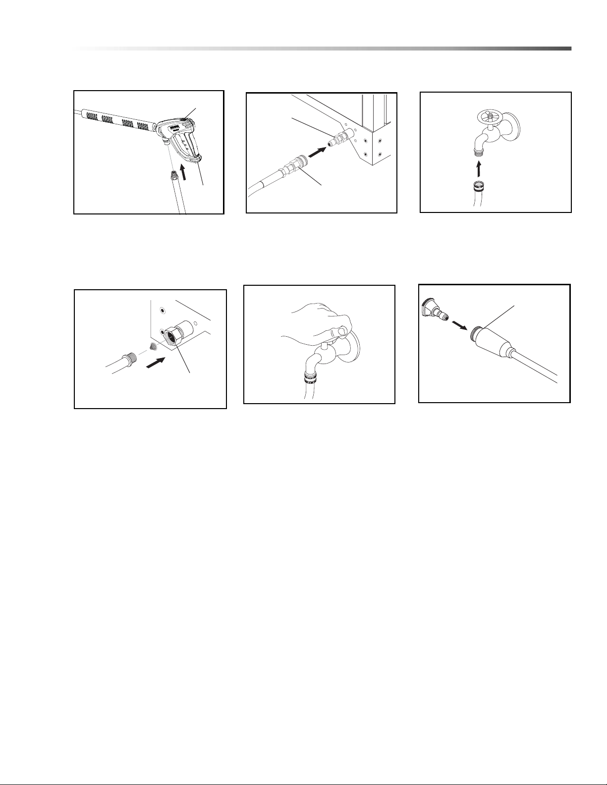
STEP 1: Attach the high pressure
hose to the spray gun using teflon
tape on hose threads. Move safety
latch into locked position to prevent
spray gun trigger from activating.
STEP 4: Connect the garden hose
to pump water inlet. Inspect inlets.
CAUTION: Do not run the pump
without water or pump damage
will result.
STEP 2: Connect the high pressure
hose to the discharge fitting. Push
coupler collar forward until secure.
STEP 5: Before installing nozzle,
turn on the water supply and run
machine allowing water to run from
the end of the wand until clear . T urn
off machine. Check for water leaks
and tighten as needed.
STEP 3: Connect garden hose to
the cold water source.
STEP 6: Pull the spring-loaded
collar of the wand coupler back to
insert pressure nozzle. Release the
coupler collar and push the nozzle
until the collar clicks. Pull the
nozzle to make sure it is seated
properly.
Landa VNG Operator’s Manual 8.913-939.0 - AB
17
Operations
Detergent
Valve
Burner Switch
Pump Switch
Burner Switch
Pump Switch
Steam Valve
Detergent Valve
Variable Pressure
Control Handle
Trigger
Variable Pressure
Wand (VP)
High
Pressure
Nozzle
Brass Soap
Nozzle
Operating Instructions
ON
OFF
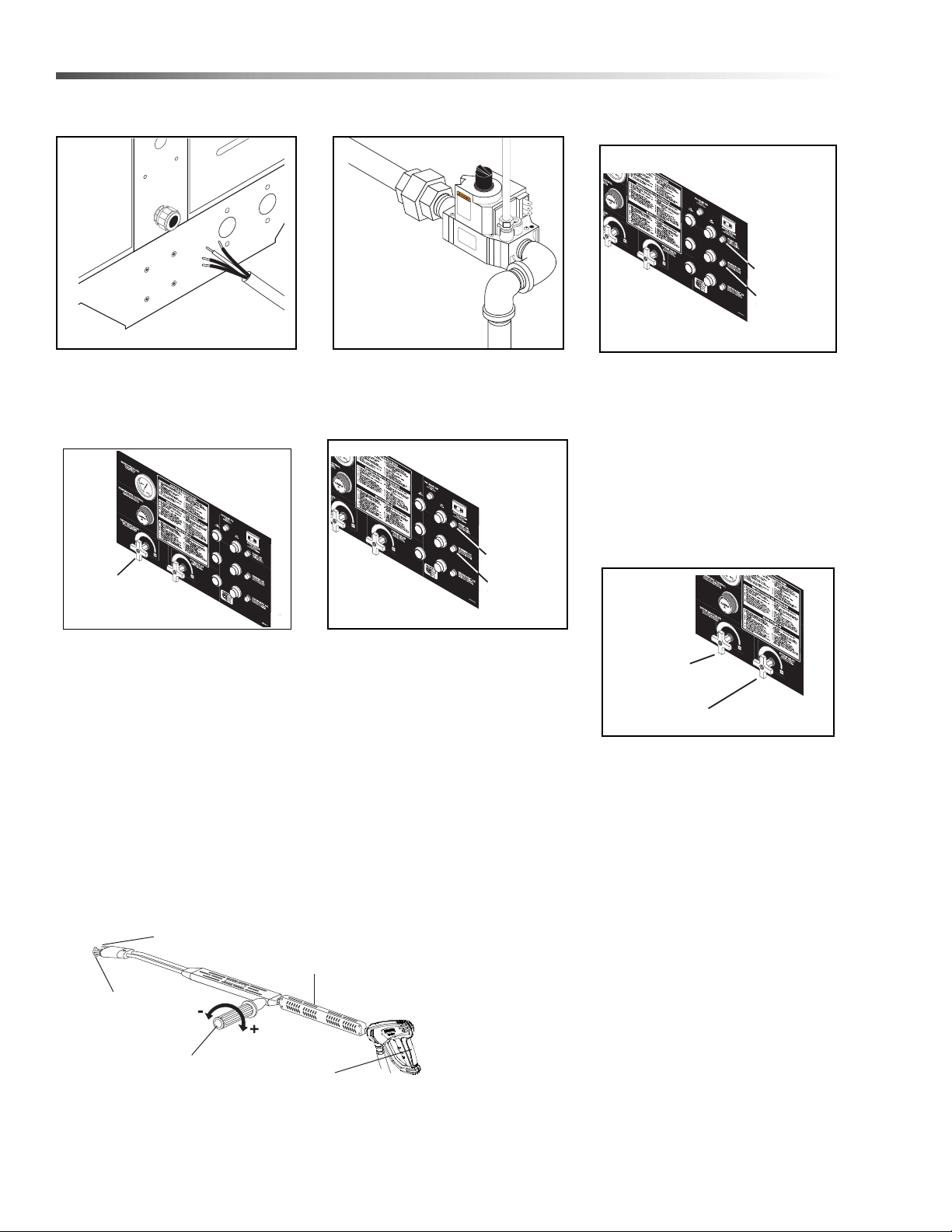
STEP 1: Have an electrician
connect power supply into electrical box according to information
shown on the serial plate.
STEP 4: To apply detergent open
the detergent valve counterclockwise making sure that the
detergent pick-up tube is in the
detergent solution and not sucking
air. With optional remotes, the
detergent switch needs to be
turned to the OFF position before
turning to the ON position to
activate the detergent solenoid.
STEP 2: Turn on main gas supply
and depress and turn control knob
to the ‘ON’ position.
STEP 5: To Stop: Turn the burner
switch off and place the detergent
pick-up tube into fresh water . Op en
the detergent valve and trigger
spray gun allowing detergent lines
to be flushed and the burner to
cool. Otherwise, coil damage will
result. After water has cooled, turn
pump switch to OFF position. If the
machine is going to be off for an
extended period of time, put the
manual valve on the gas valve into
the OFF position.
STEP 3: Push pump ‘ON’ switch, or
turn to pump position and pull the
trigger on the spray gun allowing
cold water to flow. To activate the
gas control valve for hot water,
push the burner switch to the ‘ON’
position and pull the trigger on the
spray gun.When steam is needed,
turn the steam knob counterclockwise. Then turn the temperature
adjustment knob to 275°F.
STEP 6: Close the steam knob and
detergent valve by turning
clockwise and settling the temperature control knob between 200°225°F.
NOTE: Do not allow acids,
caustic or abrasive fluids to pass
through the pump.
18
NOTE: Never run pump dry or
leave spray gun closed longer
than 3 minutes.
NOTE: Selection of high or low pressure is
accompanied by turning the handle. High
pressure nozzle must be inserted at end of wand
to obtain hight pressure. To apply soap read
operator’s manual.
Landa VNG Operator’s Manual 8.913-939.0 - AB
Operations
Detergent
Valve
WARNING
Applying Detergent &
General Operating Techniques
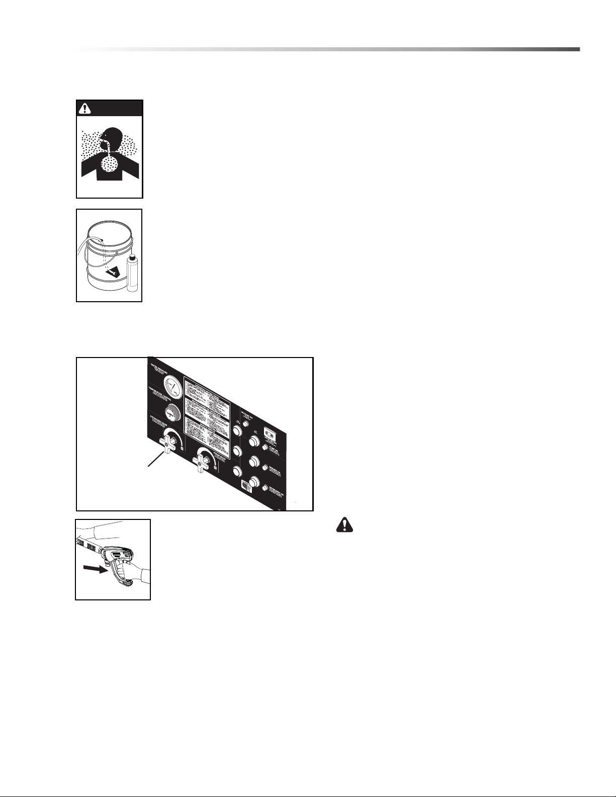
WARNING: Some detergents may
be harmful if inhaled or ingested,
causing severe nausea, fainting or
poisoning. The harmful elements
may cause property damage or
severe injury.
STEP 1: Use detergent designed
specifically for pressure washers.
Household detergents could damage
the pump. Prepare detergent solution
as required by the manufacturer. Fill a
container with pressure washer detergent. Place the filter end of detergent
suction tube into the detergent
container.
STEP 2: Open detergent valve counterclockwise until
you obtain desired mixture. Detergent will mix with the
high pressure water stream.
Thermal Pump Protection
If you run the engine for 3-5 minutes witho u t pres s ing
the trigger on the spray gun, circulating water in the
pump can reach high temperatures. When the water
reaches this temperature, the pump protector engages
and cools the pump by discharging the warm water
onto the ground. This thermal device prevents internal
damage to the pump.
Cleaning Tips
Pre-rinse cleaning surface with fresh water. Place
detergent suction tube directly into cleaning solution
and apply to surface. For best results, limit your work
area to sections approximately 6 feet square and
always apply detergent from bottom to top. Allow
detergent to remain on surface 1-3 minutes. Do not
allow detergent to dry on surface. If surface appears to
be drying, simply wet down surface with fresh water. If
needed, use brush to remove stubborn dirt. Rinse at
high pressure from top to bottom in an even sweeping
motion keeping the spray nozzle approximately 1 foot
from cleaning surface. Use overlapping strokes as you
clean and rinse any surface. For best surface cleaning
action spray at a slight angle.
STEP 3: With the motor running,
pull trigger to operate machine.
Liquid detergent is drawn into the
machine and mixed with water.
Apply detergent to work area. Do
not allow detergent to dry on
surface.
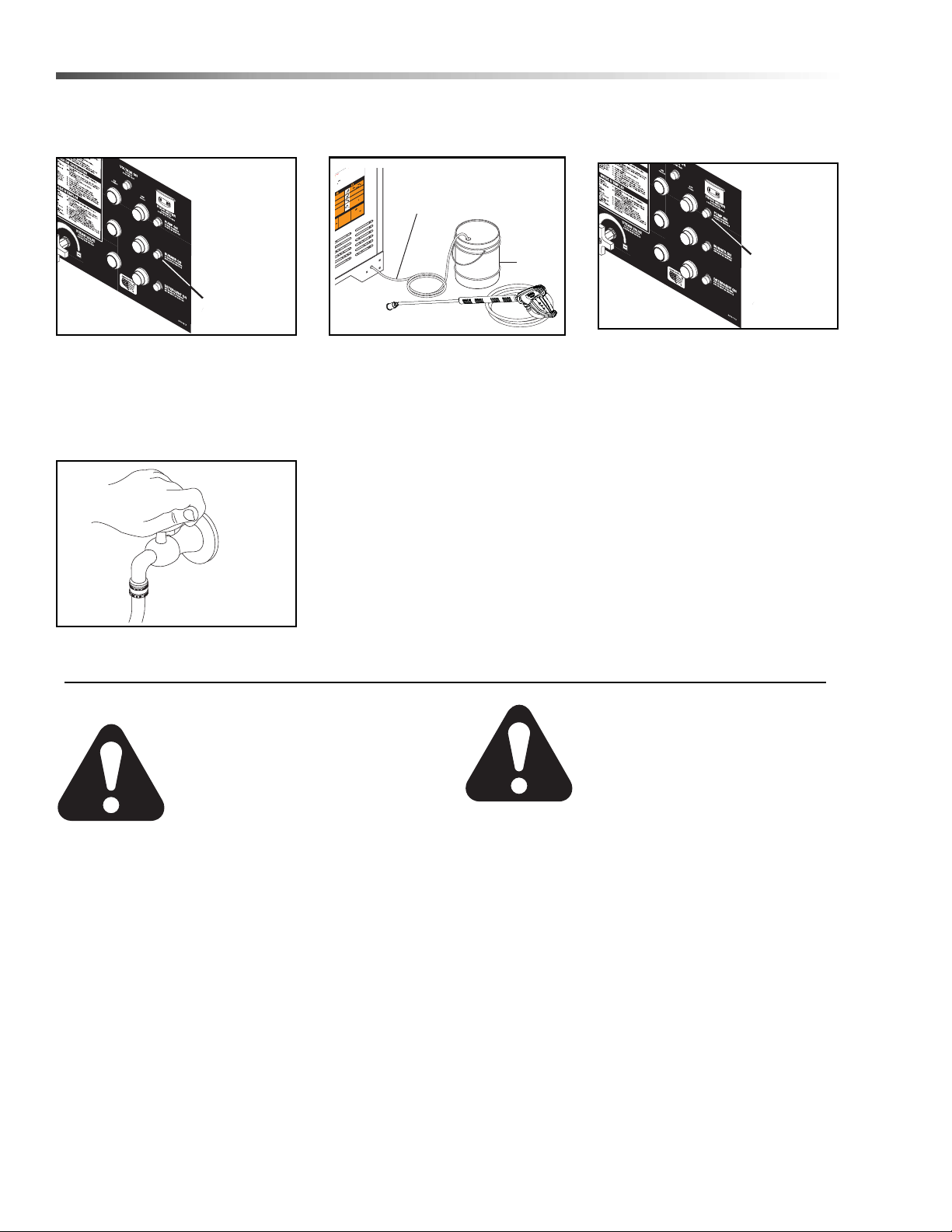
IMPORTANT: You must flush the detergent from
your pressure washer after each use by p lacing the
suction tube into a bucket of clean water, then run
the pressure washer for 2 minutes.
Recommendations:
• Before cleaning any surface, an inconspicuous
area should be cleaned to test spray pattern
and distance for maximum cleaning results.
• If painted surfaces are peeling or chipping, use
extreme caution as pressure washer may
remove the loose paint from the surface.
• Keep the spray nozzle a safe distance from the
surface you plan to clean. High pressure wash
a small area, then check the surface for
damage. If no damage is found, continue to
pressure washing.
CAUTION - Never use:
• Bleach, chlorine products and othe r co rro siv e
chemicals
• Liquids containing solvents (i.e., paint thinner,
gasoline, oils)
• Tri-sodium phosphate products
• Ammonia products
• Acid-based products
These chemicals will harm the machine and will
damage the surface being cleaned.
NOTE: If you remove detergent siphon tube from
container or allow container to empty, it will cause low
pressure by sucking air, which will damage the pump.
Landa VNG Operator’s Manual 8.913-939.0 - AB
Rinsing
Turn detergent valve clockwise to close. Operate
pressure washer and allow a few seconds for the
detergent to clear.
19
Operations
Burner Switch
Pump Switch
T
e
s
t
r
e
s
a
nd
o
ut
-
on.
g
h
t
a
CI
O
L
E
A
E
L
M
A
N
U
A
L DE
O
P
E
R
A
C
IÓN
AN
TES
DE
U
S
A
R
S
E
.
L
A O
P
ER
A
C
IN
A
D
EC
U
A
D
A
P
U
ED
E
O
C
A
S
IONA
R
L
E
S
IO
N
E
S
PE
R
S
O
N
A
L
ES
O
DA
Ñ
O
S
A
L
A
S
PR
OP
I
ED
A
D
E
S
.
N
E
.
Y
O
R
M
e
t
2
.
C
o
n
n
ct
e
m
ise
à
l
a
te
r
e
à
l’
aid
e
de
s
proc
é
d
u
d
i
s
jo
n
c
t
eu
r
.
L
e
d
is
j
o
nc
t
e
u
s
a
t
io
n
.
3.
F
i
xe
z
l
e
t
u
y
a
u
à
ha
u
te
pr
e
ss
i
on,
l
p
i
de
s
o
r
ti
e
.
4
.
C
o
n
ne
c
te
z
l
e
t
uya
u
à
e
a
u
e
t
f
ai
t
es
c
o
u
le
r
l’
e
u
5
.
T
e
n
e
z
l
e
t
u
b
e
r
igid
e
f
e
r
m
em
e
n
t
.
M
e
t
t
e
z
l’
i
n
t
e
r
r
u
p
t
ur
po
s
it
i
o
n
“
O
N
”
.
6.
T
ou
rn
e
z
l
e
bo
u
t
o
n
d
u ro
b
i
n
et
d
e
g
a
z
en
p
o
s
i
ti
o
n
“
O
N
”
.
La
ei
l
s
’
a
ll
u
m
e
a
u
t
o
m
a
ti
q
u
e
me
nt
l
o
rs
q
ue
l
’i
n
t
e
r
r
up
t
e
u
r
d
u
b
r
û
l
e
u
r
e
s
t
m
is
s
u
r
WARNIN
G
P
R
E
CA
U
C
IO
N
/
A
VE
R
TI
S
S
E
M
E
N
T
S
K
A
L
E
N
E
B
Y
O
N
G
P
ROT
E
J
A
S
E
LO
S
O
JO
S
CU
-
A
N
D
O
se
o
p
e
r
e
e
st
e
e
q
u
i
p
o
.
DE
S
L
U
N
ETT
E
S
DE
S
E
C
U
R
I
T
E
D
O
I
V
EN
T
E
T
R
E
P
O
R
T
E
ES
l
o
r
s
q
u
e
vo
u
s
o
pe
r
ez
c
e
t
a
p
p
a
re
i
l
.
e
d
e
v
e
c
t
.
u
s
r
e
s
.
u
R
I
S
QUE
D
E
F
E
U
O
U
D
’
E
X
P
LO
S
IO
N
R
IE
S
GO
D
E
IN
CEND
I
O
O
E
XPLOS
IÓ
N
O
SION
c
o
m
bu
s
t
i
bl
e
n
c
e
ar
e
a
f
o
r
s
e
s
o
m
e
g
a
s
I
f
y
o
u
s
m
el
l
tr
u
c
t
i
on
s
.
I
f
d
e
p
a
r
tm
e
n
t
.
c
g
r
e
p
ai
r
m
a
y
n
o
b
t
o
O
F
F
b
e
e
n
u
n
de
r
n
Detergent
Tube
Fresh
Water
Shutting Down And
Clean Up
.
r
v
e
a
e
e
1.
A
R
z
E
e
gl
é
r
t
e
”
ad
N
o
DE OP
I
d
O
“
o
C
S
F
.
m
ur
)
E
G
s
O
y
(
r
de
N
a
D
u
o
r
a
i
r
A
r
le
O
r
e
ic
û
i
G
I
e
r
n
a
i
i
A
t
T
b
e
C
P
a
a
u
se
r
A
r
a
d
C
o
(
e
d
r
d
de
i
n
u
F”
a
s
.
o
rd
F
te
ct
o
e
p
RU
t
p
e
O
g
-
Pé
n
“
y
T
u
n
r
r
e
e
o
i
o
ya
n
r
.
e
c
d
o
ó
s
e
t
m
t
r
i
t
ue
e
ci
e
l
NS
n
t
d
e
i
ia
I
mac
le
u
nt
l’
e
n
c
o
,
o
c
en
e
t
z
i
i
s
v
e
posi
ini
l
l
r
r
e
e
ro
r
r
t
t
e
e
e
t
z
r
o
o
r
la
u
d
p
e
u
C
n
s
e
r
t
i
ac
m
b
o
a
en
nce
r
,
m
or
m
lo
e
e
s
é
u
n
o
e
.
3
p
t
lad
e
t
d
p
”
m
ó
r
I
i
o
p
n
ea
à
n
o
’
m
c
m
d
C
o
a
l
i
t
FF
u
i
e
2
a
c
s
F
p
r
d
co
t
t
O
a
a
o
u
e
“
G
.
f
t
.
a
r
l
on
.
f
i
r
a
z
r
e
e
p
an
a
í
me
u
c
e
e
u
à l
El
t
a
d
t
N”
g
c
l
a
m
c
s
t
.
n
n
la
n
h
a)
è
I
l
i
O
n
o
a
e
i
t
A
r
i
e
“
c
t
r
v
ur
s
g
s
e
en
p
i
s
r
i
ar
t
t
y
e
ener
ND
:
.
l
o
lo
u
.
v
b
er
u
e
s
a
”
t
ptor
û
.
e
o
a
e
b
s
m
r
F
y
osi
u
u
v
a
de
r
hu
P
CE
e
g
nt
r
o
b
’
dé
d
a
m
d
r
l
e
a
i
a
e
e
d
.
N
ll
isp
n
e
OF
h
y
e
g
n
o
7
t
ol
l
t
“
(s
E
d
bo
t
r
du
t
o
er
”
o
(
n
la
t
r
i
s
e
z
I
r
t
u
cie
e
t
o
le
a
N
s
u
s)
uent
l
e
u
a
c
e
n
pi
.
f
é
h
s
s
N”
r
é
v
O
e
n
l
e
i
el
c
,
qu
d
t
“
e
b
t
va
O
e
re
g
se
la
e
n
o
p
e
a
e
di
l
é
e
n
“
l
p
p
s
n
b
ó
u
s
e
i
l
o
Ac
r d
ó
n
y
t
I
n
e
i
s
e
di
m
a
s
z
rr
o
i
ó
l
C
.
c
n
e.
e
u
t
i
è
n
a
o
i
e
or
e
e
r
o
r
8
ec
s
t
e
r
p
.
e
u
s
p
d
ic
p
s
hi
fr
P
n
u
n
p
u
1
ir
g
o
i
a
c
u
o
s
e
a
o
Ap
l
l’
u
a
p
os
rr
r
a
o
d
a
m
t
C
.
d
se
p
e
l
a
do.
C
a
e
e
m
e
gla
r
l
9
é
i
a
.
ez
a
de
d
e
a
u
.
t
o
l
s
in
a
2
n
t
u
r
u
l
q
e
p
A
o
l int
c
e
n
r
u
l
q
r
e
z
ob
e
t
e
d
r
e
o
e
e
our r
z
e
b
t
s
a
o
c
sus
i
p
e
M
.
s
e
p
o
.
d
n
a
u
s
in
i
a
l
u
i
v
B
a
or
r
et
q
gas
d
uer
nd
l
a
m
a
a
e
p
a
g
a
o
lo
L
u
e
u
t
ter
e
em
n
o
s
ad
eb
q
.
s
s
d
u
i
a
in
c
C
cu
C
e
e
a
q
p
l’
ru
l
m
e
.
l
d
ps
p
u
d
z
e
a
ba
e
l
l
a
v
a
l
m
e
l
l
i
e
d
r
t
ent
r
e
á
u
r
era
t
e
.
tu
et
v
r
o
u
.
nez
t
pr
a
am
u
)
g
a
va
M
r
au
l
n
p
c
g
i
n
a
e
O
l
t
u
’e
io
e
a
l
r
p
t
á
D.
D
se
r
c
z
m
m
.
.
A
l d
A
m
A
e
e
a
o
o
a
te
t
nte
r
l
p
t
se
).
i
z
.
t
3.
n
AG
l
a
e
n
E
e
l
ie
e
P
e
t
ou
e
i
o
u
p
r
DO
s
c
A
a
C
I
c
e
q
(
e
o
m
U
u
i
o
D
”
n
l
.
g
a
t
erá au
q
r
F
F
de
o
N
e
a
o
—
ta
a
l
l
F
u
E
C
nd
s
f
p
la
o
te
.
l
n
N
C
.
o
i
l
)
“O
e
s
ce
c
j
4
N
,
m
O
n
e
er
e
u
IO
n
to
i
r
co
a
e
p
D
ó
c
u
(E
S
S
e
e
a
i
d
t
A
n
o
”
a
c
d
gu
.
i
l
l
i
r
e
a
5
N
G
se
e
on
m
c
l
o
os
A
d
O
PLO
t
ue
e
o
e
“
p
No
P
t
o
3
q
X
s
r
l
.
s
pr
i
.
ó
a
o
a
a
E
(A
l
u
t
j
r
y
e
p
os
”
ol
2
ue
r
a
n
E
d
F
r
C
g
á
El
se
e
len
te
y
ti
i
D
o
F
l
.
r
.
a
n
t
i
n
)
p
t
c
6
s
e
O
e
“O
O
U
do
a
e
g
.
njua
e
r
G
ermi
a
DO)
s
n
D
a
e
d
I
e
e
p
S
ó
gu
e
t
—
i
y
u
m
D
:
a
d
E
e
ucto
n
em
i
n
e
I
e
N
N
d
a
u
u
e
t
ar
d
R
st
i
l d
E
A
i
q
e
q
O
u
n
osic
n
i
ro
p
I
e
l
s
s
e
p
C
p
rg
l
S
el
g
a
7.
e
l
N
a
r
lim
d
la
O
d
e
c
E
e
de
r
ma
nd
t
(
L
r
o
a
e
e
l
es
en
e
P
l
s
e
s
d
ión
X
i
a
n
o
upt
r
s
a
do
E
b
r
u
i
o
e
’
Enci
r
n
y
r
i
u
l
m
p
e
pués de
ù
D
.
p
t
u
q
o
a
ue el d
n
s
i
8
l
o
v
b
g
E
in
a
e
o
l
s
áq
a
t
s
D
a
r
i
l
el
e
p
m
a
t
a
o
.
QU
i
r
a
9
a
a
p
v
S
.
A
l
d
i
g
.
de
n
n
í
r
er
al
A
RI
t
e
on
o
p
ue
Ne
.
n
t
.
P
q
x
ra
a
e
e
O
u
a
.
up
p
s
e
i
j
r
r
p
a
gu
S
.
B
e
e
a
m
E
er
a
N
s
r
t
OF
D
T
l
e
n
O
i
.
de
I
p
e
l
s
C
istol
EN
o
e
S
e
a
SK
I
ed.
r
í
p
I
t
t
.
L
fr
re
s
a
it
n
i
R
l
a
ga
á
LO
e
n
z
n
en
i
m
CA
s
P
n
p
r
o
ne
m
a
a
X
e
l
P
l
S
o
u
p
.
E
E
e
e
a
I
s
t
l
r
l
esio
D
s
n
i
C
e
e
I
y
e
Pr
h
y
F
h
o
—
re
l
m
.
l
a
c
w
R
i
es
r
a
r
E
i
S
er
l
E
t
i
p
at
r
P
C
g
s
to
so
DE
l
t
U
pa
s
.
e
or
t
o
S
F
se
s
d
e
AU
n
e
H
tol
o
t l
C
s
n
— U
i
das
s.
D
p
S
d
la
i
s
me
E
e
i
u
e
é
T
a
C
l
iq
n
u
l
A
e
ig
F
s
HO
R
E
r
po
S
—
e
N
s
SU
h
Y
U
e
c
as
l
R
A
u
CO
o
n
s d
U
C
E
T
o
e
.
J
c
s
N
lé
f
N
o
a
o
I
ce
y
s
g
UEV
l
i
ES
n
F
CA
s
n
n
T
a
e
M
la
O
R
o
t
S
t
e
s
E
r
e
e
E
AN
S
a
SE
s
C
SK
N
-
So
I
A
E
U
g
A
L
R
n
B
.
IO
—
F
i
RE
.
-
s
O
E
C
p
R
d
n
—
T
A
T
i
D
A
p
n
i
S
ÓN
E
IS
r
I
R
a
O
SU
L
ER
ma
P
g
S
E
w
P
P
O
I
x
RN
E
P
d
.
A
T
u
d
O
U
R
s
U
e
L
S
e
O
n
I
P
Q
n
R
B
d
a
no
P
g
i
E
O
R
A
AL
a
à
n
s
E
L
E
U
U
r
m
P
i
u
e
T
E
E
N
n
K
E
g
s
L
d
S
T
I
e
A
T
o
C
y
T
.
E
A
E
d
N
M
IGN
.
A
-
S
O
R
ra
R
E
E
O
-
L
B
A
O
E
—
p
M
P
s
P
E
D
PA
E
S
ÓN
A
RS
ER
SO
S
e
P
O
A
A
’
L
s.
c
R
CI
S
L
A
E
L
n
ICA
O
CK
OP
A
U
L
I
a
T
F
E
S
USA
I
PE
R
c
O
S
and
E
l
D
L
P
E
O
h
A
C
a
A
ET
L
l
N K
.
D
DE
D
h
S
e
C
E
N
t
N
A
d
R
A
E
o
U
S
O
GU
A
I
E
a
b
P
N
E
r
US
P
T
T
ER
A
e
Y
R
h
E
A
t
N
V
u
A
M
f
D
O
S
E
E
SE
I
I
I
wi
R
D
e
E
S
L
L
s
P
I
L
d
.
GO
l
a
S
TIL
T
S
S
o
E
S
E
CA
U
ue
U
E
E
H
q
N
I
I
T
éng
A
E
t
F
LIR
to
R
I
N
s
IO
n
—
a
o
A
TR
S
GU
r
AL
t
V
-
N
E
A
.
Ma
o
U
A
a
LE
.
E
l
T
E
l
i
—
S
S
a
Q
D
u
r
OI
A
i
S
.
q
R
ua
n
D
A
N
S
o
g
e
ION
O
t
G
b
UR
a
S
R
E
e
N
ON
E
T
d
A
.
Se
del
S
R
O
.
C
I
S
P
R
S
S
T
R
E
A
A
C
RE
T
P
DE
l
E
L
U
J
ON
e
A
O
Do
S
I
t
a
N
T
.
j
S
I
A
e
—
.
j
ri
e
ES
S
Y
s
e
L
zl
E
a
D
l
di
R
I
i
z
n
OF
B
r
R
n
U
o
o
U
e
P
E
J
n
g
ge
L
rs
i
.
r
D
r
f
N
SK
e
F
i
s
I
I
a
o
US
p
d
E
e
R
E
r
s
O
s
.
u
a
S
G
a
sch
RE
s
b
i
e
p
e
R
E
SQU
E
d
s
cl
e
V
t
A
D
nn
RI
N
c
U
H
de
e
ep
so
n
A
r
r
C
i
—
i
e
H
e
o
S
.
l
d
K
I
E
p
C
s
I
D
T
or
el
U
es
on
R
e
A
d
s
s
O
r
E
ch
OT
-
s
i
U
r
e
t
u
S
H
e
n
p
o
A
v
t
A.
e
t
I
L
t
a
X
o
au
e v
n
FI
d
m
s
S
d’e
a
e
a
r
e
e
d
A
r
r
t
E
a
se
a
i
s
l
re.
D
t
un
y
è
O
Uti
.
l
i
n
.
G
m
e
da
E
-
s
S
I
.
i
ù
a
e
é
E
X
o
r
I
m
d
cu
Y
é
R
s
ucto
e
r
r
t
de
i
d
d
a
u
PH
n a
o
o
a
n
c
r
o
r
S
ie
u
p
r
n
p
d
A
r
b
’
ó
e
s
n
o
i
l
t
t
i
h
n
c
e
D
oi
su
-
a
a
y
r
l
re
t
l
E
x
n
d
d
a
n
z
n
U
anc
o
e
l
p
e
o
au
le
l
c
en
Q
d
p
t
p
l
u
S
l
a
c
e
I
’
u
pe
l
un
a
m
e
p
n
er)
R
d
p
i
ne
u
s
n
e
h
p
a
e
s
n
i
n
e
c
e
ch
d
cc
a
c
o
n
K
rè
z,
-
d
a
i
r
a
.
C
p
Ke
l
d
u
ma
u
s’
d
l
.
.
.
ga
p
n
s
t
o
n
l
e
s
r
a
s
et
e
u
le
a
e
u
ut
ce
e
i
t
c
r
e
o
l
c
g
i
i
e
r
d
r
p
ri
a
d
a
e
S
TION
in
t
g
n
ou
’
e
a
l
l
o
F
c
.
e
U
m
p
e
d
z
e
c
u
s
O
wir
ê
l
deur d
C
e
a
ue
n
o
e
l
e
i
ou
o
l
th
d
m
g
O
q
K
a
s
e
(
ff
n
s
e
R
S
s
m
é
ic
instal
o
u
s
u
e
I
n
la
r
d
T
o
s
t
e
o
d
de
r
r
l
r
d
u
R
ro
nc
e,
f
a
c
r
C
u
b
n
r
g
o
i
g
p
e
z
e
f
nt
t
o
ne
l
ct
a
c
e
a
y
n
s
e
LE
l
eu
r
e
el
y
.
r
ur
e
ct
m
s
o
r
E
ne
N
-
e
o
bu
s
m
e
u
e
F
d
t
sion.
i
em
l
o
t
az
r
p
l
t
o
plus
t
o
m
n
é
g
u
r
r
o.
s
l
C
o
.
a
r
t
n
f
ê
’
o
r
d
d
a
o
n
l
p
g
u
t
n
e
e
c
p
y
x
p
o
iscon
—
n
t
s
u
i
o
d
i
fo
e
er
t
é
e
n
s
D
u
e
c
cua
l
N
s
c
i
s
d
wa
.
o
e
e
p
e
s
z
ô
s
v
e
Ó
s
va
r
v
r
r
I
e
ur
a
a
t
u
e
t
n
l
ad
i
n
c
un
e
e
C
nt
ga
o
o
n
t
r
n
e
e
s
r.
S
ay
o
v
i
e
U
p
o
s
u
e
t
e
s
s
r
e
.
e
l
c
A
n
r
c
c
e
r
t
C
i
en
n
p
te
s
e
nt
r
a
o
u
e
m
n
s
n
s
ap
t
O
n
p
u o
ai
e
o
e
p
gée
o
u
h
e
t
t
h
n
e
ne
p
l
r
R
p
e
r
p
s
c
f
o
ef
n
o
.
u
m
i
T
e
d
a
m
i
e
al
c
nc
o
e
b
s
o
ci
s
o
e
l
c
t
n
,
e
C
c
é
i
p
a
c
t
-
s
n
c
e
l
r
p
i
u
E
n
ly
r
e
u
at
n
m
p
mm
a
i
i
u
L
r
i
u
la
l
e
.
out
a
n
o
o
p
d
i
E
nn
r
’
pp
e
e
co
d
o
r
é
l
s
j
u
é
se
t
e
e
i
d
c
S
u
a
l
E
e
e
co
o
m
u
.
i
é
e
r
p
s
i
r
nt
m
r
p
f
D
s
z
t
,
a
s
n
u
e
a
pe
oc
n
t
a
o
o
m
ê
c
0
a
se
va
h
r
i
l
i
O
p
e
u
c
s
l
g
t
t
c
i
a
i
0.
at
ti
a
s
t
mi
G
e
u
n
r
9
p
r
u
”
r la
,
i
a
s
u
p
No
S
re
eu
e
e
l
e
d
.
d
-9
e
l
s
S
E
b
p
pa
s
t
pa
18
o
I
n
o
p
0
e
.
e
n
l
t
ain
o
l
a
a
r
r
u
de
0
e
R
i
e
e
s
l
e
ô
p
u
a
n
re
r
9
m
n
i
i
re
e
.
d
e
g
o
tr
e
su
o
u
a
8
a
d
d
n
ca
ect
m
la
l
i
e
t
l
r
p
N
e
r
r
n
r
on
pou
t
s
t,
ad
e
e
5
e
.
t
à
l
o
b
de
o
c
ré
i
n
s
n
l
n
i
e
a
d
d
e
an
c
a
e
t
o
re
e
e
e
e
é
r
e
u
b
s
r
o
t
d
M
i
i
d
n
e
de
q
ci
r
n
e
m
é
i
r
c
nd
’
v
e
i
isa
b
e
s
u
.
n
ar
a
r
s
e
r
er
v
t
p
s
ro
o
o
h
p
t
m
y
y
t
al
a
c
e
s
ui
se
o
A
t
p
e
ad
sa
b
.
t
o
u
g
e
l
e re
ee
l
s
F
éq
i
a
s
t
n e
s
b
es
n
d
t
e
e
p
F
a
u
o
e
e
p
u
f
l
a
d
e
l
O
o
c
r
n
e
e
l
s
m
r
o
d
a
e
r
e
o
e
n
t
l
n
á
,
a
u
t
o
l
i
l
e
r
ro
c
l
n
o
s
t
i
ip
e
S
,
is
,
e
t
me
eg
l
i
u
d
i
o
s
o
a
i
t
ppe
r e
m
l
q
n
l
n
on m
d
u
a
A
e
e
,
é
con
ra
t
s
a
n
l
pos
r
t
.
s
c
l
.
a
e
e
o
ia
a
u
s
n
n
E
p
c
m
d
p
a
e
r
e
5
e
n
a
Es
ió
s
e
i
l
.
r
e
’
e
s
l
eed
a
l
s
ve
e
r
N
d
v
r
a
a
s
a
g
nme
on
o
e
i
t
s
g
plo
n
r
s
c
mo
n
x
e
a
p
r
e
t
sp
to
e
e
l
d
a
s
a
t
n
r
e
i
r
t
e
rar
n
o
v
A
c
i
ie
r
e
y
a
e
c
pa
o
o
a
p
t
i
o
,
e
d
z
o
e
d
s
s
r
li
u
a
de
u
n
a
a
e
a
g
-
st
q
e
g
z
d
a
nt
c
r
e
e
or
p
e
loca
a
po
n
i
u
a
p
e
Fo
o
a
t
p
mi
,
n
.
n
a
ier
a
o
u
l
lf
r
com
b
r
ot
A
o
se
n
l
u
e
.
i
n
o
e
h
s
h
itado
u
n
p
c
a
l
e
ar
e
e
g
a
t
e
u
ja
l
s
u
u
ni
e
q
ap
.
.
s
r
s
a
c
o
o
o
e
s
r
ment
ci
m
ar
l
i
de
N
a
co
a
v
e
a
t
l
r
ag
c
en
l
ni
i
e
p
to
c
e
s
S
a
ued
n
éc
o
t
n
p
e
e
e
e
l
l
d
n
d
e
a
o
i
u
o
r
d
o
t
o
c
c
ip
i
s
n
ar
u
.
a
es
o
s
cn
c
b
q
c
nt
p
é
e
o
l
t
a
a
n
e
e
u
s
t
k
n
l
un
o
s
t
ag
o
e
r
u
t
on
n
e
E
c
c
on
i
l
mi
i
o en
te
ut
d
a
ul
l
s
o
rgi
n
N
e
o
m
C
u
.
s
e
t
n
e
n
t
c
pe
s
n
i
o
t
STEP 1: Turn the burner switch to
the ‘OFF’ position.
STEP 4: Turn off water. Protect
from freezing.
Storage
CAUTION: Always store your
pressure washer in a location
where the temperature will not fall
below 32°F (0°C). The pump in this
machine is susceptible to
permanent damage if frozen.
STEP 2: Place the detergent tube
in fresh water and open the
detergent valve and spray gun,
allowing the detergent lines to be
flushed and the burner to cool.
Otherwise coil damage may occur.
STEP 3: After water has cooled,
push or turn pump switch to ‘OFF’
position. If the machine will be
turned off for an extended period of
time, put the gas cock on the gas
valve in the ‘OFF’ position.
CAUTION: Failure to follow the
above directions will result in
damage to your pressure washer.
FREEZE DAMAGE IS NOT COVERED BY
WARRANTY.
1. Stop the pressure washer, squeeze spray gun
trigger to release pressure.
After Extended Storage
CAUTION: Prior to restarting, thaw out any
possible ice from pressure washer hoses, spray
gun or wand.
2. Detach water supply hose and high pressure hose.
3. Turn on the machine for a few seconds,
until remaining water exits. Turn pump off
immediately.
4. Do not allow high pressure hose to become
kinked.
5. Store the machine and accessories in a room
which does not reach freezing temperatures.
20
Landa VNG Operator’s Manual 8.913-939.0 - AB

Operations
Preventative Maintenance
1. Check to see that water pump is properly
lubricated.
2. Follow Winterizing Procedures to prevent freeze
damage to the pump and coils.
3. Always neutralize and flush detergent from system
after use.
4. If water is known to be high in mineral content, use
a water softener in your water system or de-scale
as needed.
5. Do not allow acidic, caustic or abrasive fluids to be
pumped through the system.
6. Always use high grade quality Landa cleaning
products.
7. Never run pump dry for extended periods of time.
Shut off timer will be set for two minutes.
8. Periodically descale coils. Contact Landa dealer for
instructions.
It is advisable, periodically, to visually inspect the
burner. Check air inlet to make su re it is not clogged or
blocked. Wipe off any oil spills and keep this equipment
clean and dry.
The areas around the Landa washer should be kept
clean and free of combustible materials, gasoline and
other flammable vapors and liquids.
Call your Local Dealer for Assistance. Tampering with
the factory setting may cause personal injury and
or property damage, and will void the manufacturer's
warranty.
Winterizing Procedure
Damage due to freezing is not covered by warranty.
Adhere to the following cold weather procedures
whenever the washer must be stored or operated under
freezing conditions.
During winter months, when temperatures drop below
32°F, prot ec tin g you r mac hin e ag a inst free zin g is
necessary. Siphoning a small amount of antifreeze into
the system is recommended. This is done by pouring a
50:50 mix of antifreeze and water into th e float tank and
then siphoning 100% antifreeze through the detergent
line with the pump on. If compressed air is available, an
air fitting can be screwed into the float tank strainer
fitting and by injecting compressed air, all water will be
blown out of the system. The use of a draft diverter will
prevent the wind chill factor from freezing the coil.
High Limit Hot Water Thermostat
For safety, each machine is equipped with a high limit
control switch. In the event the temperature of the water
should exceed its operating temperature, the high limit
control will turn the burner off until the water cools.
The flow of combustion and ventilating air to the burner
must not be blocked or obstructed in any manner.
NOTE: Pump damage may occur if ran in bypass
longer than two minutes.
Spray Nozzles
Each machine is equipped with one or more spray
nozzles, depending on model. Different spray nozzles
are calibrated for each machine depending on the flow
and pressure of that particular model. Spray nozzles
vary in bore size and angle of spray. Popular spray
angles are 0°, 15°, 25°, 40°. When ordering, please
specify size and angle of nozzle. Nozzle size for each
machine is located on the serial plate.
Unloader Valves
Unloader valves are preset and tested at the factory
before shipping. Occasional adjustment of the unloader
may be necessary to maintain correct pressure.
Pumps
Use only SAE10W-40 weight non-foaming oil.
Change oil after first 50 hours of use. Thereafter,
change oil every year or at 500 hour intervals. Oil
level should be checked through use of the dipstick
found on the top of the pump or by the red dot
visible through the oil gauge window. Oil should be
maintained at that level.
Landa VNG Operator’s Manual 8.913-939.0 - AB
21
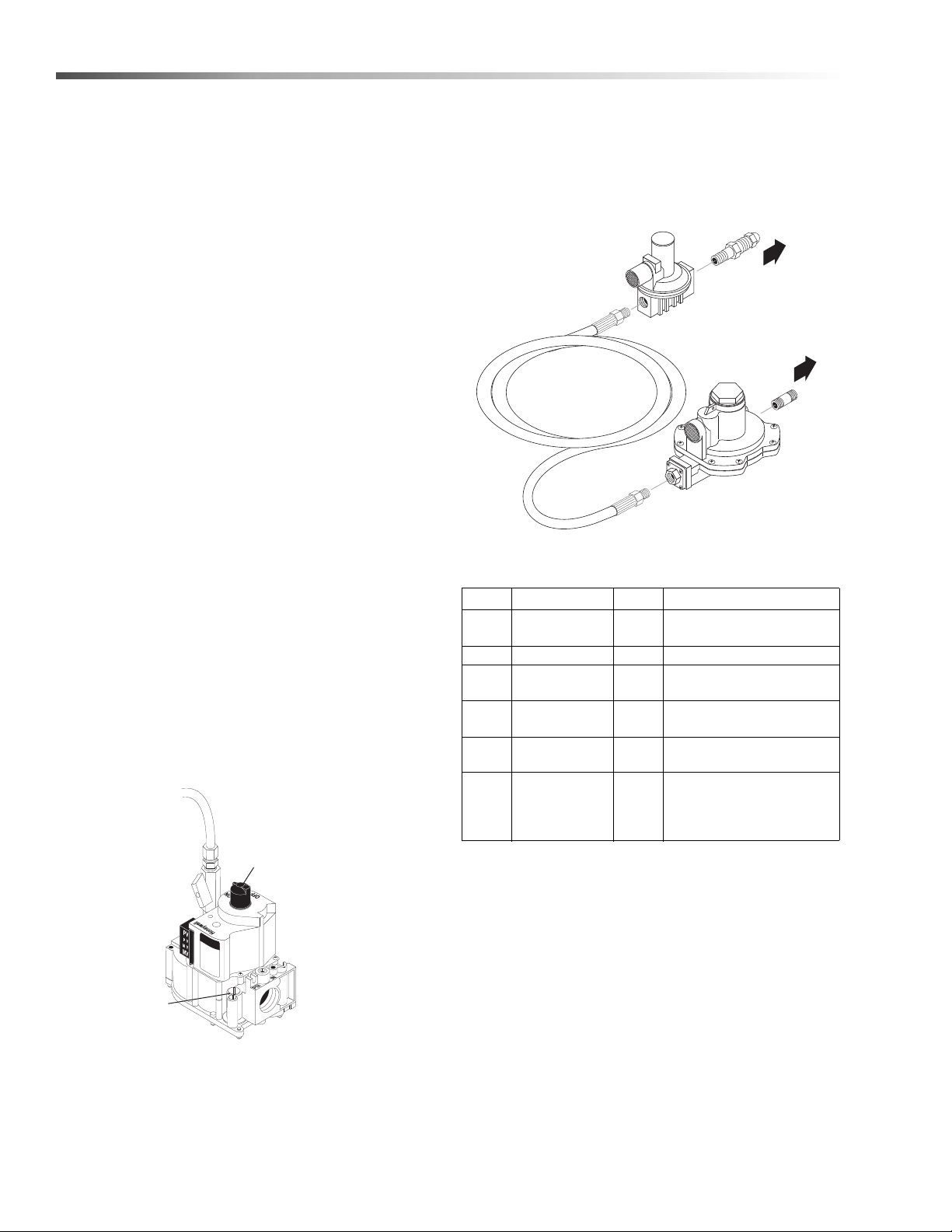
Maintenance
To Propane
Bottle
T
o
Pressure Washer
Gas Inlet
Optional Propane
Regulator Kit
9.802-633.0
Gas Valve Regulator Adjustment
On/Off
Switch
Outlet View
Inlet
Manifold
Pressure
Adjustment
Screw
Under Cap
Lines To
Pilot Light
Heating Coil
Condensation from Heating Coil
When cold water is being pumped into the water heater
coil, and the burner is on, condensation will form on the
coil and drip down into the burner compartment, giving
the appearance of a leaking coil, particularly on cold
humid days.
To Check Water Heater Coil for Leaks
With the main burner “OFF” start machine and allow it
to run a few minutes. Look into the burner compartment
with a drop light or flashlight. If no leaks are visible,
then water dripping from coil is from condensation.
Descaling Coil
In alkaline water areas, lime deposits can accumulate
rapidly inside the coil pipes. This growth is incre ased by
the extreme heat build up in the coil. The best preventative for liming conditions is to use high quality cleaning
detergents. In areas where alkaline water is an extreme
problem, periodic use of Landa Coil Descaler (part
#8.914-296.0) will remove lime and other deposits
before coil becomes plugged.
3. With a small screwdriver, rotate the adjustment
screw clockwise to increase or counterclockwise to
decrease gas pressure.
4. Replace regulator adjustment screw cap.
Periodic descaling of the heating coil is recommended so please consult your local Landa Dealer
for instructions.
Gas Valve Regulator Adjustment
Adjustment of the built-in regulator isn’t normally
necessary, since it is preset at the factory. However,
field adjustment may be accomplished as follows:
1. Attach manometer at pressure tap port.
2. Remove regulator adjustment screw cap.
REF PART NO. QTY DESCRIPTION
- 9.802633.0 1
1 9.802-019.0 1 NIPPLE, 3/4” X 2”, BLACK
2 8.717-747.0 1
3 8.717-746.0 1
4 8.711-855.0 1
5 8.717-782.0 1
REGULATOR, LP
ASSEMBLY
REGULATOR, R622CFF
FOR R932/28 & R932462
REGULATOR, HI
PRESSURE, R321H22
HOSE, 1/2” X 19”,
PROPANE
FITTING, PIGT AIL, FISHER,
M318 (INCLUDED WHEN
ORDERING PART 8.717-
746.0)
Pressure Relief Valve
Each machine is equipped with a relief valve to relieve
pressure in the system when higher than normal
operating pressures are encountered. If operating
pressure of machine is found to be normal and relief
valve continues to leak, repair or replace the va lv e.
CAUTION: Relief valve can become obstructed by
deposits and must be unscrewed at least once per
year to allow discharge.
22
Landa VNG Operator’s Manual 8.913-939.0 - AB

Maintenance
Propane Gas
General Safety Precautions
Have a qualified gas service person assist in any gas
burner installation or service. Few maintenance people
or mechanics are knowledgeable in gas controls or
related safety practices. Propane gas is heavier than
air; unburned propane gas will gravitate to the floor
rather than rise out of the stack. Hence, adequate floor
space and good ventilation are especially impor ta nt
with propane systems.
Gas Pressure Requirements
All propane fired machines operate on vapor propane
fuel only . The y are designed to operate at a pressure of
1 1 w .c.i. (between 1/3 and 1/2 of one psi), and are often
operated at even higher pressures when extra heat is
needed.
Exterior regulators are needed to control the system.
Propane bottles are not included with the machine. A
high pressure regulator should be installed on the
propane bottle and a low pressure regulator attached to
the pressure washer.
Propane Cylinder Capacity
An important consideration with propane systems is the
capacity of the supply cylinder relative to the needs of
the burner. The burner operates on propane as a vapor
gas. As gas is used from the propane cylinder, the
liquid in the cylinder boils to maintain vapor gas
pressure. This boiling process cools the liquid, and in a
heavy, continuous-demand situation, the liquid
temperature can fall to the point at which it cannot
provide vapor gas as rapidly as is needed. In this ca se,
it may be necessary to warm the propane cylinder by
directing a warm spray, not over 120°F, on the cold
cylinder or by manifolding two propane bottles together
to increase total vaporization capacity. It is recommended that a minimum 100 lb. vapor propane bottle
be used on the machine, depending on the length of
running time desired.
Burner Features
Operated Automatic Valve
This machine is equipped with an Intermittent Pilot
Ignition System. This system is designed to eliminate
the need for a constant burning pilot. Lighting of the
pilot is accomplished through electronic spark ignition
each time the burner and flow switch call for heat. The
pilot is not burning when there is no call for heat. Do not
attempt to light the appliance manually as a burn injury
or electrical shock may result. The pilot light will remain
on and the main gas valve is turned off when the spray
gun is closed.
Care of Main Burner
Due to condensation from heater coils dripping down
on the burners, scale build-up may occur in the burner
jet orifices.
1. TO REMOVE BURNER MANIFOLD FROM
WATER HEATER COIL
Turn off the gas to the main burner by turning the
knob to the “OFF” position on the gas valve and
the main gas supply.
Disconnect the pilot and ignition lines from the
gas valve. Disconnect union in main burner line
below thermostat. Slide burner manifold out
through shell opening.
2. TO CLEAN BURNER JETS
Select proper size drill for type gas involved. Use
pin vise to hold drill and ream out each jet orifice.
CAUTION: Do not ream out orifices to a
larger size.
If the water heater will be exposed to freezing weather,
an anti-freeze solution should be circulated throug h the
coil by whatever means are available for the particular
system the water heater is used on.
Landa VNG Operator’s Manual 8.913-939.0 - AB
23
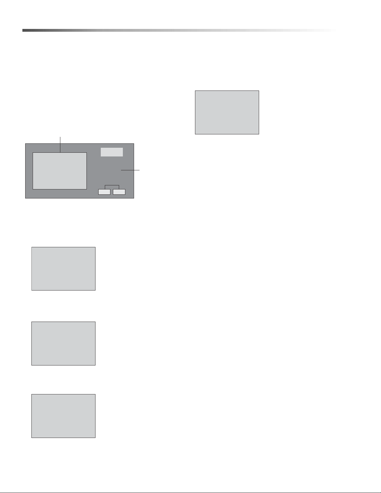
Maintenance
Mo 10:15
2006-10-13
S
WX
T
ESC OK
Default Display Screen
Arrow
Key Pad
Stop
Program
> Setup
Network
Diagnostics
Msg Config
Start Screen
>
Clock
LCD
Menu Language
Switch to OP
>
Set Clock
S/W Time..
Sync
Set Clock
Wed. 11:10
2016-12-14
Smart Relay Instructions
Digital Timer (Optional)
The following are instructions on how to set the parameters on the digital timer in Programming Mod e. To
define these settings please follow the steps below.
Setting the Clock:
1. Press the ESC key located next to the display
window and under the arrow key pad
Pressing the ESC key will access the Parameter
Assignment Menu.
2. Using the up/down arrow keys or , move the
(>) cursor to 'Setup' and press OK to accept.
NOTE: When setting time on clock, use only
military time.
The cursor is now positioned on the weekday and
shows the following on the disp lay window (see figure
below).
5. Select the time of day by using the up down arrow
keys or .
6. Move the cursor to the next position by using the
left/right arrow keys or .
7. To change the value use the up/down arrow keys
or .
8. To set the date, repeat steps 6 and 7.
9. To accept your entries press OK.
10. To go back to the previous menu at anytime press
ESC.
Programming Instructions
3. Move the (>) cursor to 'Clock' and press OK to
accept.
4. 4.Move the (>) cursor to 'Set Clock' and press OK
to accept 'Set Clock'.
The 900/1400 can be configured to run in Time Delay
or Auto Start/Stop with lockout. Machines are factory
set with Auto Start/Stop with 4 hour Lockout. A Smart
Relay controls how the machine will operate by using
three internal timers; these timers are adjustable. The
following is a brief description of these timers:
Timer 1: 'Lockout Timer' (Time Delay)
Timer 1 de-energizes (lockout) the machine if not being
used for a preset time. If machine has ‘Locked out’ it
can only be re-energize by pressing the ‘Pump On’
switch. Timer 1 is factory set to 4 hours.
Timer 2: 'Auto Start/Stop Timer'
Timer 2 allows the pump to run in bypass for a preset
time. If the pump runs in bypass longer than the allotted
time the timer will drop power to the motor contactor
and machine will be in standby mode. Squeezing the
gun trigger will restart the pump (if Timer 1 has not
locked out). Timer 2 is factory set to 30 seconds.
24
Landa VNG Operator’s Manual 8.913-939.0 - AB
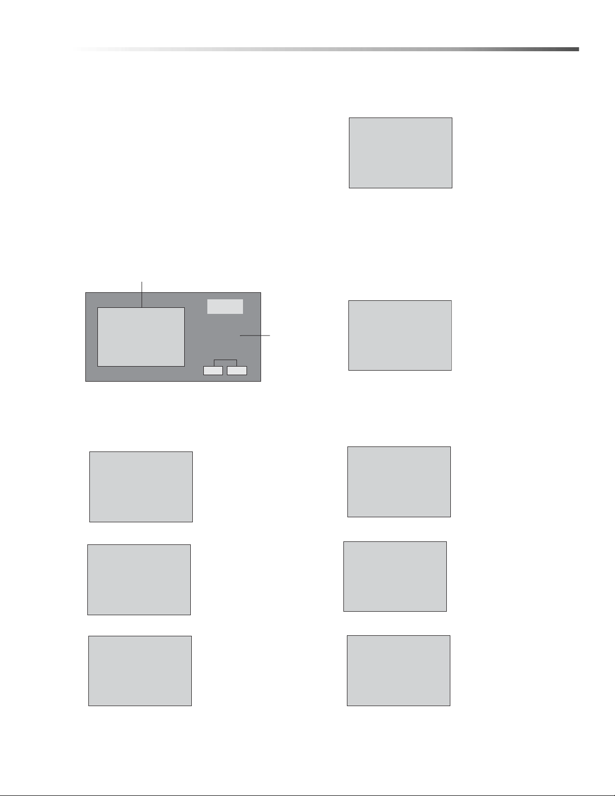
Maintenance
Mo 10:15
2006-10-13
S
WX
T
ESC OK
Arrow
Key Pad
Setup
Network
Diagnostics
Stop
Program
>
>
Set Parameter
Prog Name
TIMER-1
TIMER-2
TIMER-3
TIMER-1 1/1
T =04:00h
Ta =00:00
TIMER-1 1/1
T =04:00h
Ta =00:00
TIMER-2
T =30:00s
Ta =30:00s
1/1
TIMER-3
T =15:00s
Ta =00:00
1/1
Setup
Network
Diagnostics
Stop
Program
Timer 3: 'Reset Delay Timer'
Timer 3 controls ho w long the pump must run before
resetting the ‘Lockout Timer’ (Timer 1). This allows the
pump to run long enough to re-pressurize the system if
there is pressure loss when not in use. Timer 3 is
factory set to 15 seconds.
To change to the parameters of the internal timers in
the Smart Relay complete the following steps:
1. Turn on the power to the machine and press the
start switch. Remove the front panel and then the
control panel cover. NOTE: Use extreme caution
when reaching into the control box, the
machine has live power. Once powered the
Smart Relay window will display the Default display
screen. (See below)
Default Display Screen
NOTE: Ta is the accumulator timer and T is the
adjustable timer (the variable that changes)
5. Press OK to change the value of Timer 1. Using
the left/right arrow key
or , move the
cursor to the desired
Fig. 5
6. Each timer has optional units of time in seconds
(s), minutes (m), and hours (h). To change the unit
of time use the left/right arrow keys or to move
the cursor to the unit field. Change the unit of time
using the arrow up/down keys or . Once all
the values have been set press OK to accept. (See
figure 6)
field and press OK.
Next, use the up/down
arrow keys or to
change this value.
(See figure 5)
2. Press the ESC key located next to the display
window and under the arrow key pad (see figure
2). Pressing the ESC key will access the
Parameter Assignment Menu.
Fig. 2
3. Using the up/down
arrow key or ,
move the (>) cursor to
'Program' and press
OK to confirm (See
figure 3).
Fig. 3
4. The display window
Fig. 4
shows the three parameters. (See figure 4)
Landa VNG Operator’s Manual 8.913-939.0 - AB
Fig. 6
7. Press ESC and use the arrow up/down keys or
to select the next parameter to change (Timer-
2). Repeat steps 4 and 5 to change the Timer-2
parameters. (See figure 7)
Fig. 7
8. Press ESC and use the
arrow up/down keys
or to select the next
Fig. 8
Fig. 9
parameter to change
(Timer -3). Repeat steps
4 and 5 to change the
Timer-3 parameters.
(See figure 8)
9. Once all timers have
been set to the desired
time press ESC three
times to return to the
Parameter Assignment
Menu screen.
(See figure 9)
25
 Loading...