

Karcher-Pressure-Washer-Repair-Manuals/Karcher-Pressure-Washer-Parts-and-Basic-Repair-Service-Manual-Pump-757-HD3500DB-HD3500DH-HD3500DH-QC-HD3500G-HD3501DK-HD3600DH
Karcher Karcher-Pressure-Washer-Repair-Manuals/Karcher-Pressure-Washer-Parts-and-Basic-Repair-Service-Manual-Pump-757-HD3500DB-HD3500DH-HD3500DH-QC-HD3500G-HD3501DK-HD3600DH Repair Manuals
Service Handbook
High-Pressure
Washer Pump
3.532-757.0
10.00
For Karcher Pressure Washer Parts Call 606-678-9623 or 606-561-4983
Pump 757 9/28/01 3:33 PM Page 1
www.mymowerparts.com
For Karcher Pressure Washer Parts Call 606-678-9623 or 606-561-4983
Pump 757 9/28/01 3:33 PM Page 2
www.mymowerparts.com
TROUBLESHOOTING OVERVIEW
Tools Necessary to Service the
KARCHER®High-Pressure Washer Pump
Part 3.532-757.0
Special Tools
•
Valve pliers . . . . . . . . . . . . . . . . . . . . . . . . . 4.901-062
•
Installation tool . . . . . . . . . . . . . . . . . . . . . . 2.901-034
(HP seal, oil seal)
•
Silicon grease . . . . . . . . . . . . . . . . . . . . . . . 6.288-044
(for packing and O-rings)
•
Lithium grease . . . . . . . . . . . . . . . . . . . . . . 6.288-079
(for O-rings on bypass valve)
•
Non-detergent pump oil . . . . . . . . . . . . . . . .6.288-050.0
Generic Tools
•
Allen Wrench 8mm
•
Allen Wrench 6mm
•
Torx TX30 Socket Wrench
•
Needle Nose Pliers
•
Rubber Mallet
•
Pliers
•
Flat Head Screwdriver
•
Phillips Head Screwdriver
•
Hammer
•
Safety Goggles
How to Use This Manual
It is not necessary to read this entire manual to find a solution
to a problem. This manual identifies four basic ways the pump may
malfunction. Find the section that defines the malfunction
of the pump. Turn to that section's overview page and identify
the specific problem. Then go to the solutions page for that
specific problem. If you don't know what the problem is, work your
way through the problems listed until you find and correct the problem.
Low Water Pressure . . . . . . . . . . Section 1
Water Leaks . . . . . . . . . . . . . . . . . Section 2
Oil Leaks . . . . . . . . . . . . . . . . . . . Section 3
Detergent Delivery Failure . . . . . Section 4
Always wear safety rated eye protection and clothing.
For any other problems contact KARCHER
®
technical support
at 1-800-877-2424.
3
For Karcher Pressure Washer Parts Call 606-678-9623 or 606-561-4983
Pump 757 9/28/01 3:33 PM Page 3
www.mymowerparts.com
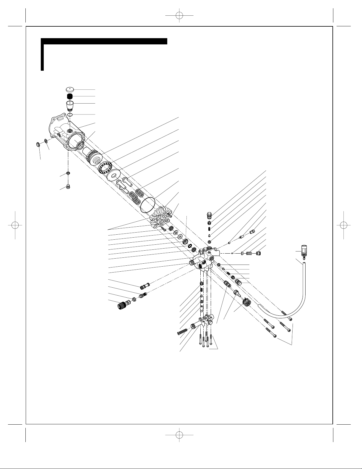
MASTER DIAGRAM
For Karcher Pressure Washer Parts Call 606-678-9623 or 606-561-4983
Pump 757 9/28/01 3:33 PM Page 4
8...Oil level
sight glass
9...Oil drain
drain plug
7...Sight
glass seal
plug ring
10...Oil
1...Oil vent cap
2...Oil filter
3...Oil reservoir
4...O-ring
5...Oil bath housing
6...Pump shaft seal
20...Weep holes (3)
21...Oil seal (3)
22...Brass washer (3)
23...Low-pressure seal (3)
24...Bushing (3)
25...Scraper ring (3)
26...High-pressure seal (3)
27...Pump head
28...Water outlet
29...Nozzle insert
30...Bypass valve
31...Bushing
32...Pressure/volume control
33...Low pressure valve cage (3)
34...Low pressure valve spring (3)
35...Low pressure valve plate (3)
36...Low pressure valve seat (3)
37...Spacer (3)
38...Water inlet filter
39...Water inlet
40...Water inlet housing
11...Swash plate assembly
12...Swash plate roller bearing
13...Swash disk
14...Piston (3)
15...Piston spring (3)
16...Forward O-ring
17...Piston housing
18...Piston guide
retaining screw (2)
19...Circulation
hole (3)
64...Detergent non-return
check valve
57...Non-return check valve seat
58...Non-return check valve plate
59...Non-return check valve spring
60...Non-return check valve cage
42...Valve screw
62...Metering
valve knob
63...Detergent hose nipple
41...Water inlet bolt (5)
42...Valve screw (3)
43...High-pressure valve cage (3)
44...High-pressure valve spring (3)
45...High-pressure valve plate (3)
46...High-pressure valve seat (3)
47...Bushing
48...Thermal relief valve
49...Closing screw
50...Rubber cap
51...Ball bearing
52...Ball-bearing seat
53...Spring
54...Safety relief
valve screw
55...Detergent filter
with metering valve
56...Detergent tube
65...Pump head bolt (4)
www.mymowerparts.com

KARCHER OVERVIEW
When the piston (14) is pushed forward by the swash disk (13), the
low-pressure check valve (33-36) closes and water is conveyed
through the open high-pressure check valve (43-46) to the water outlet (28). The pressure that is generated is dependent upon the flow
rate and the orifice diameter of the high-pressure nozzle.
Bypass Valve with Pressure Adjustment
When the trigger of the spray gun is pulled, the entire pump capacity
flows through the nozzle insert (29) to the water outlet (28). At this
time, the bypass valve (30) remains in the upper position and closes
off the path between the pressure chamber and the suction chamber.
When the trigger of the spray gun is released, water ceases to flow
through the nozzle insert (29). The non-return check valve (57-60)
closes, and the pressure in the high-pressure hose is maintained
between the trigger-actuated valve in the spray gun and the nonreturn check valve (57-60). The pressure instantly rises in a surge,
which causes the bypass valve (30) to be pressed downwards. This
opens the path between the pressure chamber, located above the
bypass valve (30), and the water inlet housing (39). The pump continues to run only in bypass mode. The safety relief valve (51-54) will
open if the bypass valve (30) fails to activate.
When the trigger of the spray gun is again pulled, the pressure in the
high-pressure hose drops suddenly. The spring inside the bypass valve
(30), together with the restricted pressure at the entrance to the nozzle insert (29), pushes the bypass valve upwards. This causes the circulation between the pressure chamber and the water inlet (39) to
close, and the pump builds up pressure once more.
This pump has a pressure/volume control (32) that enables you to
adjust the pressure and water flow at the pump. Other pumps have a
fixed pressure rating and are non adjustable. The pump shown in the
diagram is adjustable. This adjustment is made by turning the pressure/volume control (32) downwards. This causes the bypass valve
(30) to be pushed open in a continuous movement. A part of the
pump’s capacity then flows from the pressure chamber into the water
inlet housing (39) and the operating pressure drops to the amount that
has been set by turning the pressure/volume control (32).
Thermal Protection Device
If the pump should continue to run in the bypass mode for an extended amount of time (max 5 min.), the water circulating within the pump
will reach a temperature level that will cause
internal damage. This is
prevented by the thermal relief valve (48).
The thermal relief valve will
release the hot water and then automatically reset itself.
Detergent Delivery System
In this system there is a nozzle insert (29) in the water outlet (28). The
entire pump capacity flows through the nozzle insert to the spray gun.
Detergent can only be drawn in by the nozzle insert (29) if the nozzle
of the spray wand has been set to low pressure. This causes the pump
pressure to fall to approximately 435 PSI (low
pressure), and the
greatest degree of negative pressure (11.6 PSI)
is generated at the lateral hole in the nozzle insert so that detergent can be drawn into the
unit via the detergent suction tube (56) and detergent filter (55).
If the spray nozzle on the spray wand is set for high-pressure operation, the hole in the nozzle insert (29) does not create any negative
pressure, and no detergent can be drawn into the unit.
Swash Plate Assembly
The three pistons (14) are driven by the swash plate assembly (11,12,13),
which is mounted to the engine shaft. In the case of a vertically configured machine, a drive bolt is screwed into the engine shaft and then
inserted into the pump shaft. As soon as the engine shaft rotates, the
swash disk (13) rotates as well. This causes the pistons (14) to move
backwards and forwards. The piston stroke depends upon the angle of
the swash disk (13). The greater the angle of the swash plate, the longer
the piston stroke. One revolution of the swash plate gives the pistons one
suction stroke and one pressure stroke.
Oil Bath
The swash plate assembly and pistons are bathed in oil (oil type 15W40
non-detergent). The oil level should be halfway up the sight glass (8)
located in the oil bath housing (5). It is important that the machine is on
level ground when checking the sight glass.
In order to drain the oil, the drain plug (10), located beneath the oil bath
housing (5) will have to be removed. To add oil, remove the vent cap (1)
from the oil reservoir (3) and add to the required level.
Note: Some pumps do not have a drain plug, oil reservoir and sight glass.
In order to add oil in this case, the pump head (27) and piston housing
(17) will have to be removed. If servicing a pump without a sight glass,
the oil level is just above the high side of the swash disk (13).
Pistons With Seals
The three pistons (14) are pressed against the swash disc (13) of the
swash plate assembly (11,12,13) by powerful springs (15). These three
pistons are manufactured from tempered, surface-hardened steel and are
non-corrosive with regards to detergents and rust.
The pump delivery capacity is determined by
- the rotational speed of the motor
- the diameter of the pistons
- the length of the piston stroke.
The pistons (14) in industrial units are fitted with a high-pressure seal
(26) and a low-pressure seal (23). Non-industrial units have only a highpressure seal (26).
The three pistons each have an oil seal (21) mounted in the piston housing (17). These three oil seals, along with the shaft seal (6), retain the oil
in the oil bath housing. The slot holes (20) are in the piston housing (17)
and allow water or oil to drip out into the open.
A water leakage rate of one drop per piston per minute is allowable during high-pressure operation. If oil is leaking from the weep holes (20),
there is either a leak in the oil seals or there is piston damage.
Low-Pressure and
High-Pressure Check Valves
Each piston works with one low-pressure check valve (33-36) and one
high-pressure check valve (43-46). Each of these check valves is constructed of the same basic components: the valve cage, spring, valve
plate with guide shaft and the valve seat with O-ring.
The sealing surface between the valve plate (35 & 45) and the valve seat
(36 & 46) is conical. The valve plate and valve seat are manufactured
from either plastic or stainless steel depending upon the particular unit
involved.
When the piston (14) is forced backwards by the spring (15) in the oil bath
housing (5), the high-pressure check valve (43-46) closes and water is drawn
in through the supply line / suction chamber at the water inlet (39), through
the inlet filter (38), and through the open low-pressure check valve (33-36).
5
For Karcher Pressure Washer Parts Call 606-678-9623 or 606-561-4983
Pump 757 9/28/01 3:33 PM Page 5
www.mymowerparts.com
The detergent non-return valve consists of a small spring (16) with a
ball, O-ring and nipple. When operating in the
detergent mode, the neg-
ative pressure created by the nozzle insert
causes the ball to be drawn
away from the O-ring, against the tension of the spring. Detergent can
then be drawn into the unit.
When operating in the high-pressure mode, the ball seals off the
detergent connection so that no water can flow into the container
of
detergent.
6
KARCHER OVERVIEW
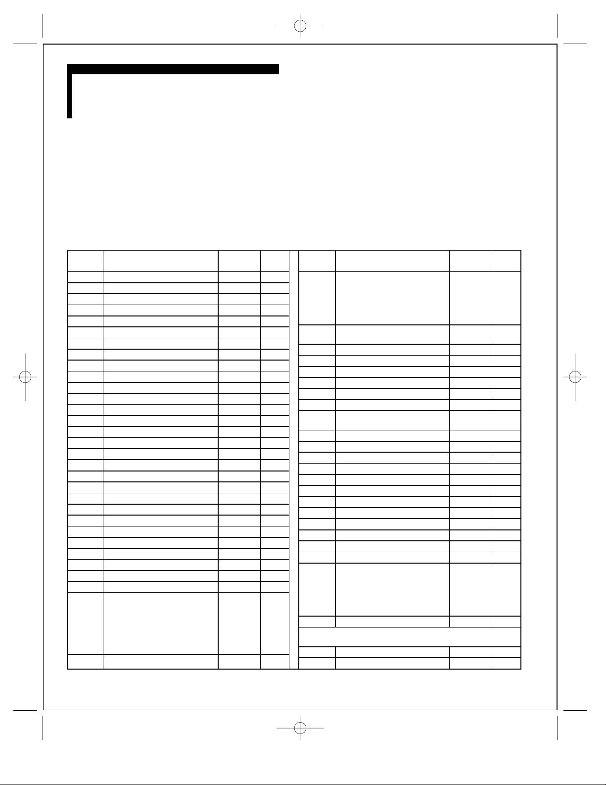
PART NUMBERS
High Pressure Washer Pump 3.532-757.0
ITEM #(S)
DESCRIPTION PART # QTY. IN
PUMP
1 Oil vent cap 5.063-651.0 1
2 Oil filter 5.132-107.0 1
3 Oil reservoir 5.070-194.0 1
4 O-ring 6.362-168.0 1
5 Oil bath housing 5.060-827.0 1
6 Pump shaft seal 7.267-011.0 1
7 Sight glass seal 6.362-585.0 1
8 Oil level sight glass 5.411-062.0 1
9 Oil drain plug ring 7.362-055.0 1
10 Oil drain plug 7.382-233.0 1
11 Swash plate assembly 5.120-324.0 1
12 Swash plate roller bearing 6.401-334.0 1
13 Swash disk (included with part #11) NA 1
14 Piston 4.553-173.0 3
15 Piston spring 5.332-403.0 3
16 Forward o-ring 6.363-963.0 1
17 Piston housing 5.060-676.0 1
18 Piston guide retaining screw 7.306-023.0 2
19 Circulation hole (incl. with item #24) NA 3
20 Weep holes (included with item #17) NA 4
21 Oil seal 6.365-322.0 3
22 Washer 5.115-493.0 3
23 Low pressure seal 6.365-351.0 3
24 Bushing 5.112-402.0 3
25 Scraper ring 5.115-492.0 3
26 High-pressure seal 6.362-408.0 3
27 Pump head 5.550-273.0 1
28 Water outlet (included with item #27) NA 1
29 Nozzle insert 5.769-141.0 1
30 Bypass valve (multiple numbers)
top o-ring set 6.362-977.0 1
valve top 5.553-363.0 1
spring 5.332-425.0 1
valve seat 5.581-214.0 1
valve seat o-ring 6.362-450.0 1
threaded spindle 5.305-263.0 1
31 Bushing 5.110-630.0 1
ITEM #(S)
DESCRIPTION PART # QTY. IN
PUMP
32 Pressure/volume control knob with 5.321-307.0 1
Spindle 5.291-073.0
Grooved pin 7.314-629.0
Spindle gasket 6.362-468.0
Valve Screw 5.583-147.0
Valve screw gasket 6.362-989.0
33,34 Low-pressure valve cage, spring, 4.580-329.0 3
35,36 plate and seat
37 Spacer 5.110-608.0 2
38 Water inlet filter 6.414-282.0 1
39 Water inlet (included with item #40) NA 1
40 Water inlet housing 5.060-809.0 1
41 Water inlet bolt 7.306-044.0 5
42 Valve screw 5.583-146.0 1
43,44 High-pressure valve cage, spring, 4.580-379.0 3
45,46 plate and seat
47 Bushing 5.115-876.0 1
48 Thermal relief valve complete 6.413-067.0 1
49 Screw cap 5.411-150.0 1
51 Ball-bearing 7.401-908.0 1
52 Ball-bearing seat 5.582-075.0 1
53 Spring 5.332-075.0 1
54 Safety relief valve screw 5.583-089.0 1
55 Detergent filter 4.862-032.0 1
56 Detergent tube 6.388-216.0 1
57-60 Non-return check valve housing 5.402-523.0 1
62 Detergent metering valve knob 5.321-318.0 1
63 Detergent hose nipple 5.443-281.0 1
64 Detergent non-return check valve with 5.402-523.0 1
top o-ring 6.362-151.0 1
gasket 6.326-383.0 1
ball 7.401-908.0 1
spring 5.332-124.0 1
retainer pipe 5.028-692.0 1
65 Pump head bolts 7.306-125.0 4
NOT PICTURED IN DIAGRAM
Garden hose connection 9.154-009.0 1
Piston spring retaining clip 7.343-478.0 3
For Karcher Pressure Washer Parts Call 606-678-9623 or 606-561-4983
Pump 757 9/28/01 3:33 PM Page 6
www.mymowerparts.com
 Loading...