

Page 1
BEFORE BEGINNING TO
BUILD...................................2
SAMPLE STEP................................................................3
REQUIRED TOOLS
.........................................................4
WARRANTY INFORMATION
..........................................5
PREPARING THE RADIO SYSTEM
...............................5
ASSEMBLY................................................................6-26
REPLACEMENT PARTS...............................................26
OPERATION.................................................................27
KYOZ7125 No. 40602
Entire Contents © Copyright 1996
Page 2
IMPORTANT: PLEASE READ THROUGH THE ENTIRE
INSTRUCTION MANUAL BEFORE BUILDING THE
SEABREEZE 600.
We want your experience of building this model to be a
success. So before you remove any parts from their
packages and begin assembly:
• Read through the entire manual carefully to make sure
that you are thoroughly acquainted with the model.
• If for any reason you think this model may not be for you,
return it immediately. Please Note: Your hobby dealer
cannot accept a model kit for return after assembly
has begun.
• The Kyosho Seabreeze 600 is a sophisticated radio
controlled sailboat. Sailboats are no harder to operate
than any other boat. With time and practice, you will
come to enjoy the serenity of operating sailboats. If you
follow the directions closely, the Kyosho Seabreeze 600
will provide many years of enjoyable R/C sailing.
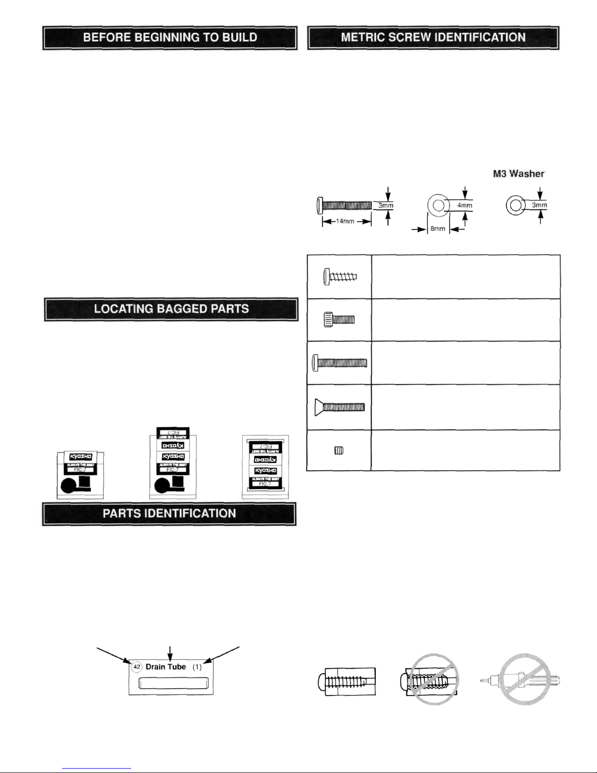
This Kyosho instruction manual uses a cross-reference
system to help you locate all of the bagged parts. DO NOT
open each bag and dump out the parts. Carefully remove
the header card from the bag and discard the staple. Slip
the header card into the bag or tape it to the outside of the
bag so that the bag number shows. This will help you find
parts when you need them.
REMOVE THE
HEADER CARD
SLIP CARD
INTO BAG
OR
TAPE TO
OUTSIDE
On pages 26 of this instruction manual, you will find a
complete list of replacement and optional parts. If you need
to replace a part, consult this guide for the manufacturer's
stock number for the items needed. In the left margin of
each page of instructions you will find a directory of small
parts that will be used in each step. For ease of
identification, these parts are shown actual size, enabling
you to place the part directly on the picture to ensure you
have selected the appropriate part.
Key Number Part Name Quantity Used
All nuts and bolts used throughout this kit are metric size.
Therefore, some of the notations may not be familiar to
you. An M3 nut is a 3 millimeter (3mm) nut. An M3 x 14
screw is 3mm in diameter and 14mm long. Some round
parts may be labeled as an "M3 Washer" (a washer with a
3mm inside diameter) or an "M4 x 8 Bushing" (a bushing
with a 4mm inside diameter and an 8mm outside
diameter). A few different types of screws are used in the
construction of your model. Here are some examples and
how they will be indicated in the instructions.
M3x14Screw Bushing
Set Screws have a hex head that requires a hex
wrench. These are for joining parts where the
head of a screw may interfere with other parts.
Flat head (F/H) screws have a fine thread and a
tapered head. This allows the head of the screw to
be flush with the part it is holding so that the screw
head does not catch on anything.
Screws have a fine thread and are used with nuts
most of the time. They are for high stress joints
where strength is required.
A cap screw is used where two pieces of metal
are to be joined. The hex head allows a hex
wrench to be used, providing more torque
for tightening.
A self-tapping (S/T) screw has a coarse thread
and is used to thread into plastic. Be careful not to
tighten the screw too much. This may strip
the plastic.
IMPORTANT SCREW INFORMATION:
Do not use excessive force when tightening self-tapping
screws into plastic. Over-tightening will cause the threaded
portion of the plastic to strip. It is recommended to stop
tightening when some resistance is felt as the head of the
screw contacts the part. Avoid using power screwdrivers
when assembling your kit. They tend to overtighten screws.
Do not use thread locking compound on self-tapping
screws. The thread locking compound may damage the
plastic. Use thread locking compound only on screws that
are fastened with a nut or threaded into a metal surface.
Correct
Incorrect
Power Screwdriver
2
Page 3
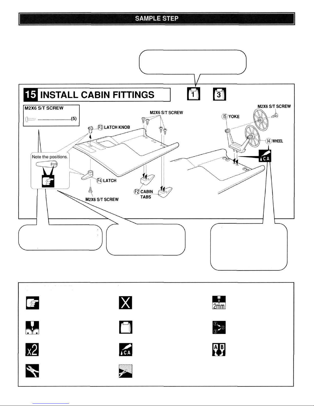
To help you get acquainted with how to use this manual, a sample step is shown below. Take a few minutes to study this
step so that you understand what some of the symbols mean. Below the sample step you will find a symbol guide.
A similar symbol guide will be shown at the bottom of each page of assembly steps.
The parts located in this box are
shown full size. Also shown is the
part name and quantity required for
this step.
Many symbols may be used in
each step. Check the symbol
guide for an explanation of the
symbols used.
All parts except screws, washers
and nuts are identified with a key
number. If a replacement part is
required in the future, find the key
number of the part needed in the
replacement part list on page 26.
Refer to the stock # and Mfg#
when ordering replacement parts.
The bag symbol with the number inside it
shows what bag contains the parts required
for this step. This symbol shows that the parts
are in bag
1.
(Do not actually perform this step)
SYMBOL GUIDE
This symbol means to pay special
attention to the instructions given.
This symbol requires that grease be
applied to the part.
This symbol requires that the procedure
be performed as many times as shown.
This sample shows to perform the
procedure twice.
This symbol requires you to cut off the
excess material.
This symbol means that the parts are
not included and must be purchased
separately.
The number inside this symbol shows
what bag contains the parts for that
step.
This symbol requires that thick
cyanoacrylate glue (CA) be used to
attach the parts. Be very careful with
CA—it will bond almost anything
including your fingers.
This symbol requires that the shaded
area shown be removed from
the part.
This symbol requires that a hole be
drilled to a specific size. This sample
would require a 2mm (1/16" or
5/64") hole.
This symbol requires that the parts
be assembled in a specific order.
This symbol requires that 6-minute
epoxy be used to assemble the
parts. Warning: Read and follow all
instructions included with the epoxy.
Some people have allergic reactions
to epoxy and its fumes.
3
Page 4

Some precautions need to be observed when building your
Kyosho kit to avoid problems:
1) Take time to read the instruction manual thoroughly.
2) Try to avoid working over a deep pile carpet. In the
event that a small part or screw should fall onto the
carpet, it would be difficult to find.
3) Place a mat or towel on the work surface where you will
be building the kit. This will prevent parts from rolling off
and will protect the work surface at the same time.
4)
Avoid running the boat in very cold temperatures. Both
plastic and metal parts become brittle at low
temperatures. In addition, grease and oil become
thick, causing premature wear and poor performance.
5) Trial fit all parts to ensure proper fit before attaching
them permanently.
Remove all flashing from parts before assembly,
as
shown in the example below.
6)
INCORRECT
Too much
removed.
Not enough
removed.
Do not
Use a sharp
hobby knife
to trim the
flash off.
remove the
flashing with
the cutter.
7) Important: Throughout the instruction manual
symbols are used to alert you to perform certain
procedures. A symbol guide is provided at the bottom
of each page to assist you.
THESE ARE NOT INCLUDED IN THE KIT
Phillips Screwdriver
Hobby Knife (XACR4320)
Needle Nose Pliers
(XACR2680)
Wire Cutters
Tapered Reamer (KYOR1050)
(Used for drilling holes. A drill and
bits will also work fine.)
220 Grit Sandpaper
6-Minute Epoxy (Such as Great
Planes' Pro'" Epoxy GPMR6045)
Thick Cyanoacrylate Glue (Such
as Great Planes Pro'" CA+
GPMR6008)
Rubbing Alcohol
THESE ITEMS ARE REQUIRED TO RUN THE SEABREEZE 600
2-Channel Radio
(preferably with
watertight servos.
Batteries for the
radio system
(12 AA Batteries)
If you use Nickel Cadmium Batteries in the radio
system, the batteries are recyclable. At the end of
their useful life, under various state and local laws, it
may be illegal to dispose of these batteries into the
municipal waste system. Check with your local solidwaste officials for details concerning recycling options
or proper disposal in your area.
IMPORTANT INFORMATION BEFORE BUILDING YOUR
SEABREEZE 600
Use the following diagram to
tie all the rigging knots.
4
Page 5
• For 90 days after you purchase your Seabreeze 600, Kyosho will either
repair or replace, at no charge, any incorrectly made part.
• Make sure you SAVE THE RECEIPT OR INVOICE you were given when
you bought your model! It's your proof of purchase - and we must see it
before we can honor the warranty.
• To send your Seabreeze 600 in for repairs covered under warranty, you
should send your boat to Kyosho's authorized U.S. repair facility:
Hobby Services
1610 Interstate Drive
Champaign, Illinois 61821
Attn. Service Department
Phone: (217) 398-0007 9:00 A.M. - 5:00 P.M. Central Time M-F
• For details on your return, be sure to follow steps 1-4 under the "Repair
Services Available Anytime" section.
Limit of our Liability:
Our liability under this warranty is limited to the repair or replacement by Hobby
Services of defective parts and does not include cost of shipping to us. Hobby
Services does pay the shipping expense to return warranty items to you.
Exclusion and/or Voidance of Warranty:
This warranty does not apply to damage or defects resulting from misuse,
abnormal service, damage in shipment, damage resulting from a crash or
damage caused by the batteries. The warranty is voided if the model is
modified, altered or repaired by anyone other than Hobby Services. This
warranty gives you specific legal rights, and you may have other rights that
vary from state to state within the U.S. We are sorry, but we cannot be
responsible for crash damage and/or resulting loss of the boat, radio,
accessories, etc.
Repair Services Available Anytime:
• After the 90-day warranty has expired, you can still have your Seabreeze
600 repaired for a small charge by the experts at Kyosho's authorized U.S.
repair facility, Hobby Services, at the address listed under Warranty
Information.
• To speed up the repair process, please follow the instructions listed below:
1. Under all circumstances, return the ENTIRE system: boat and radio.
2. Make sure the transmitter is turned off and all batteries are disconnected.
3. Send written instructions which include: a list of all items returned, a
THOROUGH explanation of the problem and the service needed, and your
phone number where you can be reached during the day. If you expect your
repair to be covered under warranty, be sure to include proof of date of
purchase (your store receipt or purchase invoice).
4. Also include your full return address.
Repair charges and postage may be prepaid or billed C.O.D. All repairs
shipped outside the United States must be prepaid in U.S. funds only.
Specification and Description Changes
All pictures, descriptions and specifications found in this instruction manual are
subject to change without notice. Kyosho maintains no responsibility for
inadvertent errors in this manual.
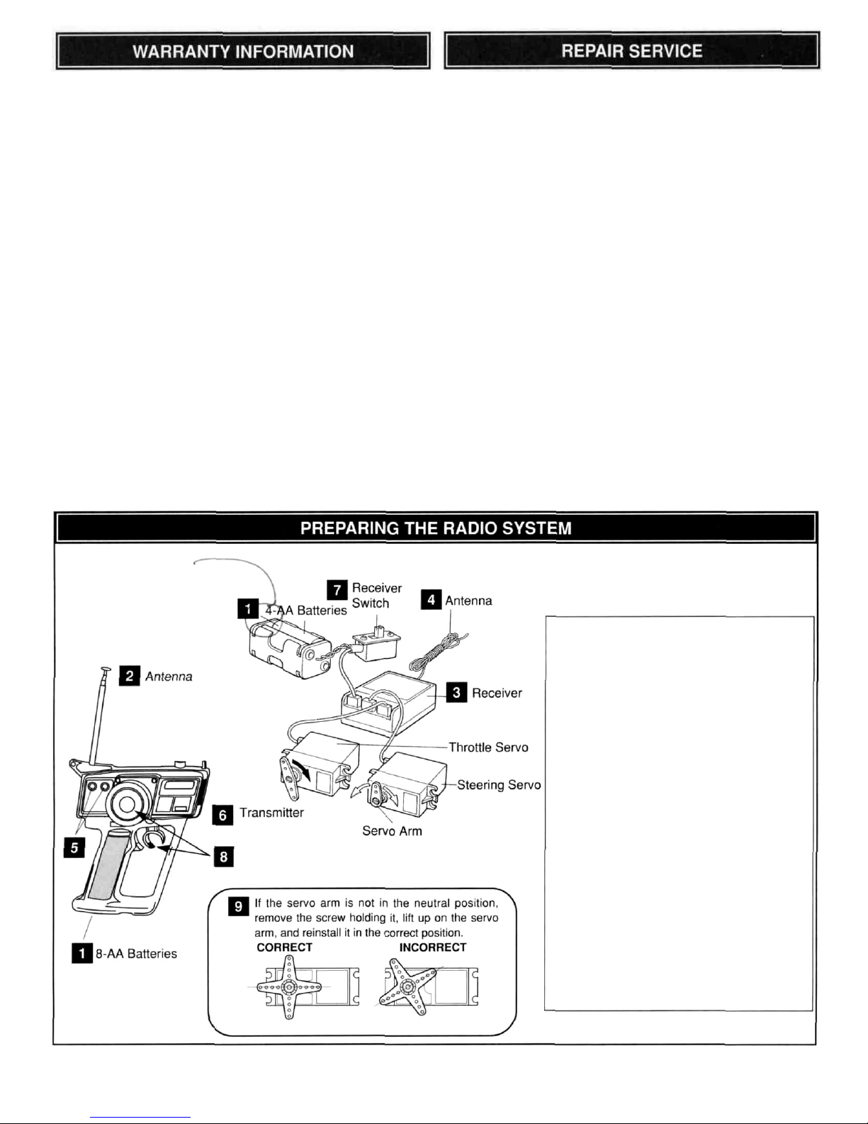
Set up the radio system following the
manufacturer's instructions and as
explained below.
1. Install the batteries in the transmitter and
the receiver battery holders.
2. Extend the transmitter antenna.
3. Connect the steering servo, throttle servo
and receiver battery to the receiver.
4. Extend the receiver antenna.
5. Adjust the servo trims to neutral position.
6. Turn the transmitter on.
7. Turn the receiver on.
8. Operate the rudder and sail control.
Make sure the servo arms move in
proportion to the movement of the
steering wheel and throttle trigger.
9. Check that the rudder and sail
servos are in the neutral position. See
diagram at left.
10. Turn the receiver off, then the transmitter.
Page 6
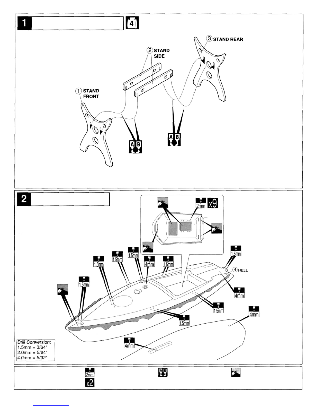
Remove the die-cut parts from the plywood
sheet and assemble as shown using epoxy.
ASSEMBLE STAND
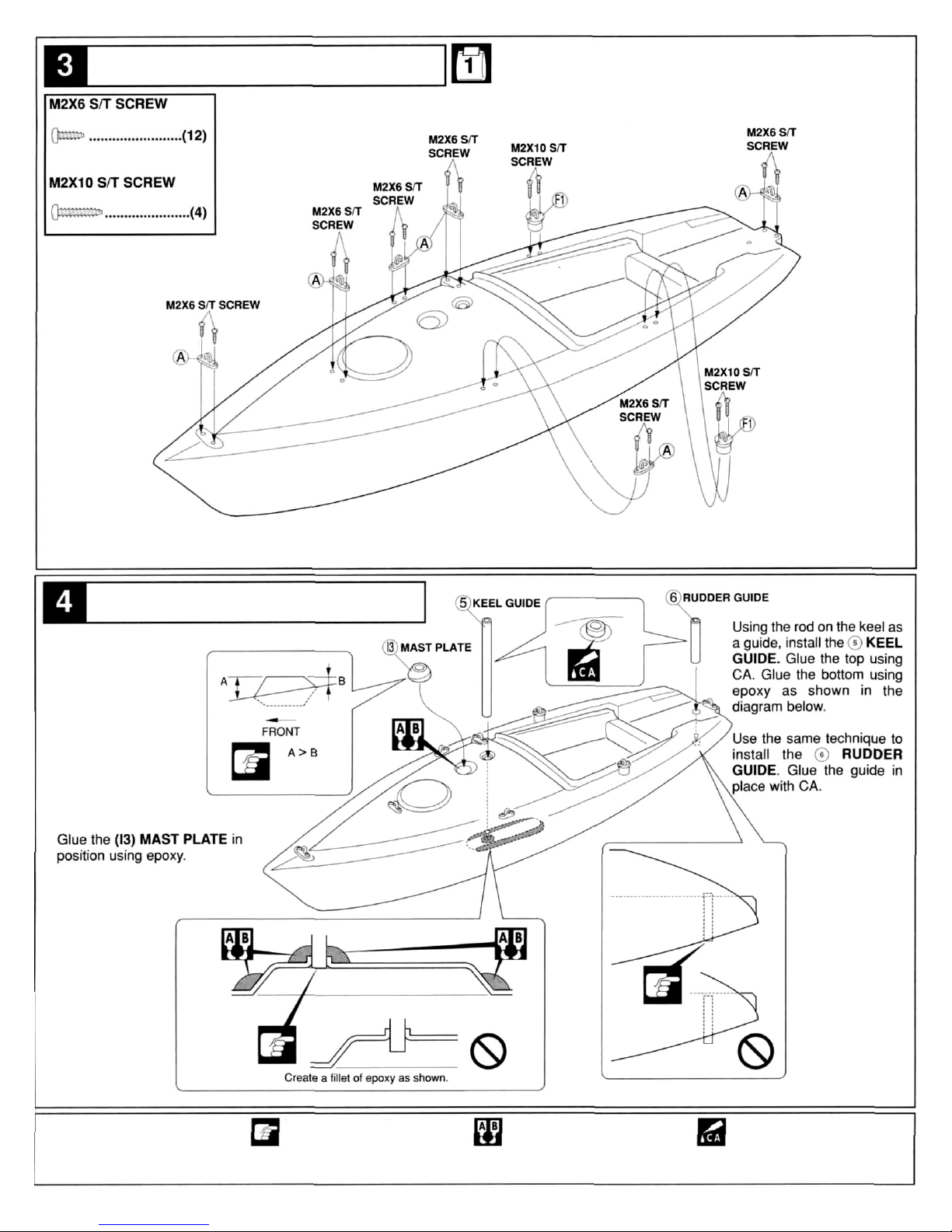
Carefully remove any flashing from the
hull using a sharp hobby knife.
Drill the holes using the sizes and
locations shown.
6
SYMBOL GUIDE
Drill hole to the specified
diameter.
Repeat this process as
many times as specified.
Apply 6-min. epoxy.
Remove the shaded
area using a hobby knife.
PREPARE HULL
Page 7
SYMBOL GUIDE
Important information.
Apply 6-min. epoxy. Apply thick CA.
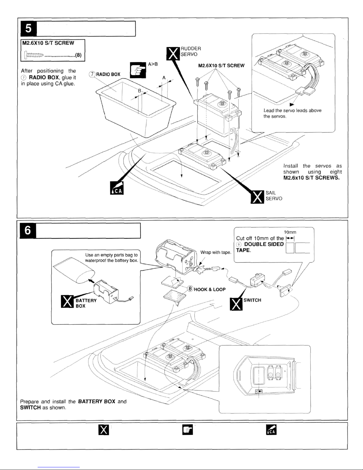
INSTALL DECK FITTINGS
Attach the fittings as shown below.
INSTALL HULL GUIDES
7
Page 8
INSTALL SERVOS
8
SYMBOL GUIDE
Not included.
Important information.
Apply thick CA.
INSTALL BATTERY
Page 9
INSTALL RECEIVER
9
SYMBOL GUIDE
Apply thick CA.
Remove shaded portion.
Assemble in this order.
Part must move freely
without binding.
INSTALL RUDDER
Page 10

INSTALL RUDDER LINKAGE
Prepare the rudder control linkage and install as shown.
INSTALL SAIL CONTROL
SYMBOL GUIDE
Make a knot.
Remove shaded portion.
Not included.
10
Page 11

INSTALL SAIL CONTROL HORN
PREPARE JIB SAIL LINES
11
Not included.
Make a knot.
Apply thick CA.
SYMBOL GUIDE
Page 12

PREPARE CABIN
12
SYMBOL GUIDE
Drill hole to the specified
diameter.
Remove shaded portion.
Repeat this process as
many times as specified.
Make a knot.
INSTALL GUIDE RING LINES
Page 13

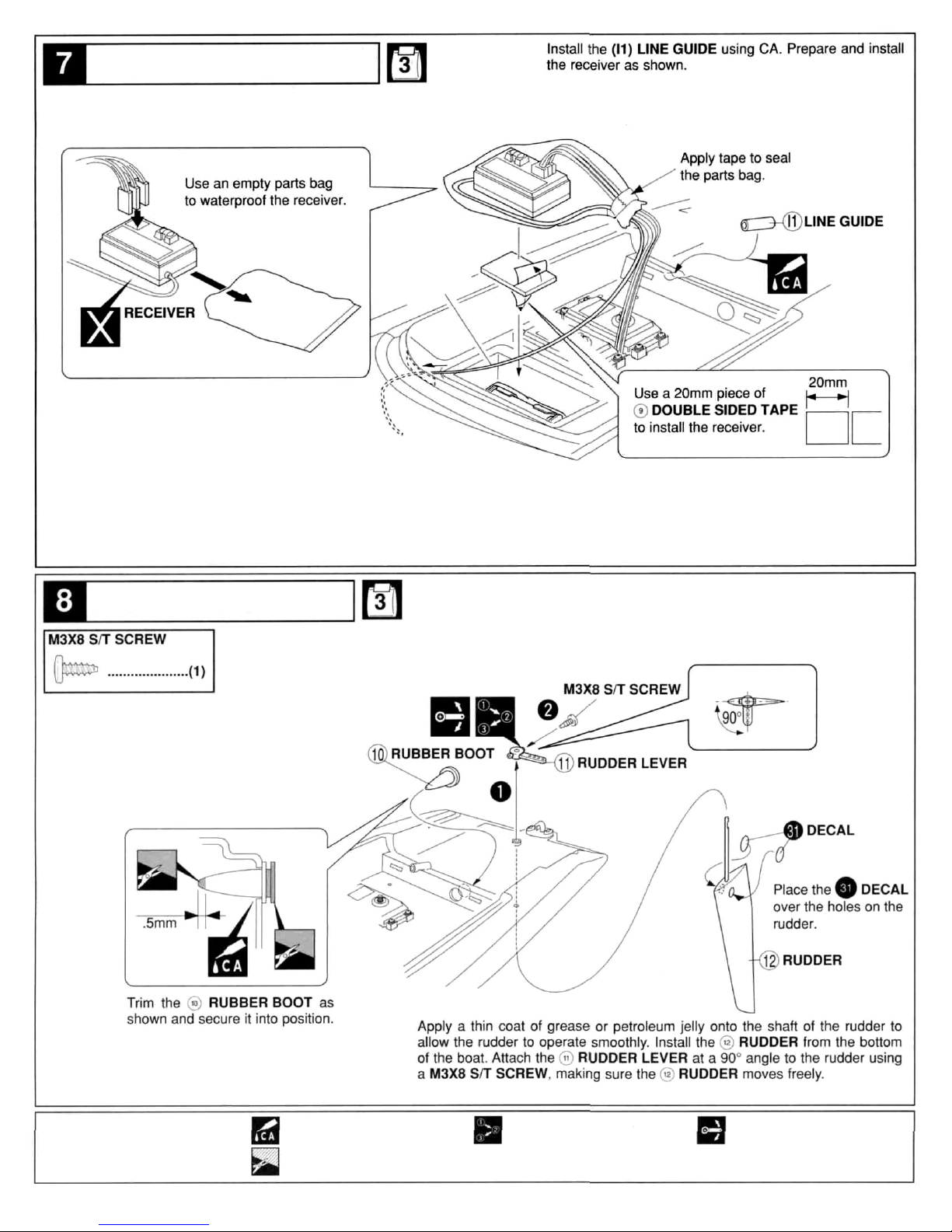
INSTALL CABIN FITTINGS
INSTALL KEEL
13
SYMBOL GUIDE
Apply thick CA.
Apply 6-min. epoxy.
Important information.
Page 14

14
SYMBOL GUIDE
Remove shaded portion.
Make a knot.
Drill hole to the specified
diameter.
PREPARE SAILS
INSTALL SAIL LINES
Page 15

PREPARE MAIN BOOM
PREPARE UPPER MAIN MAST
Prepare the main boom as shown in the diagram.
SYMBOL GUIDE
Important information.
Apply thick CA.
15
Page 16

16
Wrap the rigging line
around the cleat at
least 8 times before
securing. Attach the
main sail as shown.
SYMBOL GUIDE
Important information.
Part must move freely
without binding.
Apply CA.
PREPARE LOWER MAIN MAST
ATTACH MAIN SAIL
Page 17

ADJUST MAIN SAIL
SECURE MAIN SAIL
Attach MAIN SAIL to the MAST
as shown in the diagrams.
SYMBOL GUIDE
Important information.
Make a knot.
Apply CA.
17
Page 18

ATTACH JIB SAIL AND BOOM
18
SYMBOL GUIDE
Important information.
Apply CA.
PREPARE JIB BOOM
Page 19

INSTALL SUPPORT LINES
SYMBOL GUIDE
Make a knot. Repeat this process as
many times as specified.
Prepare the mast rigging according to the diagram.
19
Page 20

INSTALL MAST SUPPORT LINES
Attach the rigging cord prepared in the previous step as shown.
Note the lengths and attachment points of each line.
20
SYMBOL GUIDE
Make a knot.
Page 21

INSTALL UPPER JIB LINE
Install the upper jib rigging by
passing the rigging cord through the
JIB ANCHOR and tying it to the
MAST STOPPER.
MAST STOPPER
21
SYMBOL GUIDE
Make a knot.
JIB ANCHOR
Page 22

INSTALL AND ADJUST MAIN RIGGING
Attach the SNAP RINGS to the
DECK FITTINGS. Adjust the sails
as shown.
22
SYMBOL GUIDE
Important information.
Page 23

ADJUST SAILS
FRONT OF
BOAT
Use the following
diagram to adjust
the sails.
SAILS CLOSED
SAIL
CONTROL
Both the main and jib sails
should remain open 5°
when fully closed.
SAIL
CONTROL
Both the main and jib sails
should open to around
50° when fully opened.
SAILS OPENED
INSTALL CABIN
Install the cabin in the order
shown. Adjust the rigging
after installing the cabin.
Adjust so that the
distances are equal.
Assemble in this order.
Important information.
SYMBOL GUIDE
OPEN
CLOSED
23
Page 24

PLACE DECALS
• Apply numbered decals in
the positions shown.
• Decal numbers in
parentheses are placed on
the opposite side.
• Decals without numbers
can be placed anywhere.
24
Page 25

MAST ADJUSTMENT
A sailboat can be set up so that it has a tendency to either turn into
the wind (weather helm) or out of the wind (lee helm). Both properties
can be changed by adjusting the rigging. It is suggested to adjust for
a "weather helm" condition.
LEE HELM
WEATHER HELM
WIND DIRECTION
WEATHER HELM
LEE HELM
SAILING FUNDAMENTALS
When heading for point B have the rudder in
neutral position and set the sails
perpendicular to the wind.
Slowly move the rudder to the left and
maintain sail position.
When heading towards point C, adjust sails
and rudder similar to 1.
Steer hard left and close the sails at the
same time.
Return rudder to neutral and adjust sails
slowly to avoid "sail shiver."
Proceed into the wind towards point A by
tacking (zigzagging). Continue operating
sails slowly to avoid shivering.
Continue the same procedure as step 6, then
steer around point A and return to step 1.
25
SYMBOL GUIDE
WIND
DIRECTION
The closest possible heading into the
wind is a little over 45° to either side of the wind.
Any closer and the sails will "shiver" or flap.
Page 26

CLOSED
HAUL
ABEAM
QUARTER
26
CLOSED
HAUL
ABEAM
QUARTER
RUNNING
Starboard Track: Sails
are on the left of the hull.
Port Track: Sails are on
the right of the hull.
DIRECTIONAL SAILING
WIND DIRECTION
Page 27

If you have followed all of the previous instructions and find
everything to be operating properly, your Seabreeze 600 should
now be ready to run! Here are the procedures that should be
followed (some of these things may already be completed):
1. If your radio system has rechargeable batteries, charge the
transmitter and receiver batteries according to the
manufacturer's instructions.
2. Tear a paper towel in half and place the two halves in the
bottom of the mechanical compartment to absorb any
moisture that may enter the hull.
Warning: Before proceeding, make sure that no one in the
area is operating a transmitter on the same
frequency (channel) as yours.
3. Turn on the transmitter and receiver in that order.
4. Attach the hatch.
5. Check to make sure the sail and rudder are operating
properly. Note: Looking at the boat from the rear, the trailing
edge of the rudder must move to the right when the
transmitter steering wheel/stick is turned right (clockwise).
6. Ask yourself, "If the boat becomes stranded in the water, will
I be able to retrieve it either by waiting for the wind to blow it
in to shore or by using a retrieval boat?" There is always a
chance of something going wrong and the boat going
"dead"; therefore, you should always have a plan for
retrieval in that event.
9. Your Seabreeze 600 will often take on a little water,
especially when running in rough water or when making
very tight turns. Keep a roll of paper towels handy and dry
out the hull after every run. If you notice excessive amounts
of water in the hull, check for leaks especially around the
hull/deck joint. Always store your Seabreeze 600 with the
hatch and radio box cover removed to allow the interior
to dry out completely. If you neglect to do this, it may
result in corrosion of the electronic components.
10. Check the keel and rudder for weeds or other debris.
Remove any foreign material which may have become
entangled.
11. When you have finished for the day, dry the boat inside
and
out.
Important Note: If, for whatever reason, your boat takes on a
large amount of water, swamps or sinks, causing the radio
equipment to get wet, you must do the following: Immediately
remove all batteries and radio equipment from the boat. Open
the receiver (if water entered the plastic bag) and servo cases (if
not watertight servos), and dry all components completely before
reassembling. To dry electrical components, use a paper towel to
absorb the water droplets, then use a hair dryer to make sure
they are completely dry. Use compressed air to dry out all wire
connectors. (Use eye protection when working with compressed
air.) Dry the inside of the boat. Reinstall the components and
check for proper operation before running. -
Caution: If you go out in a boat to retrieve a model boat, be
sure to wear an approved flotation device. Never
swim or wade in the water to retrieve a model
boat.
7. Place the boat in water that will allow the keel to clear the
bottom. Make sure that the bottom is free of debris that may
tangle with the keel.
8. Immediately after removing the boat from the water, place it
on its stand and remove the hatch. This will allow air to enter
and help carry away moisture that may have entered the
radio comparment.
27
 Loading...