

Page 1
※ご使用前にこの説明書を良くお読みになり十分に理解してください。
Before commencing assembly, please read these instructions thoroughly!
R
THE FINEST RADIO CONTROL MODELS
LENGTH : 660mm
RADIO CONTROLLED
ELECTRIC POWERED SURFER
組立/取扱説明書
INSTRUCTION MANUAL
KYOSHORCサーファー
KYOSHO RC SURFER
目 次 INDEX
●キットの他にそろえる物
REQUIRED FOR OPERATION
●組立て前の注意
BEFORE YOU BEGIN
●プロポの準備
RADIO PREPARATION
●本体の組立て
ASSEMBLY
●ニカドバッテリーの取扱いの注意
PRECAUTIONS WHEN USING A NI-CD BATTERY
●電動ボートの取扱い
HOW TO HANDLE ELECTRIC POWERED BOATS
●スペアパーツ・オプションパーツリスト
SPARE PARTS & OPTIONAL PARTS
4〜13
15〜17
2
2〜3
3
14
18
安全のための注意事項
この無線操縦模型は玩具ではありません!
●この商品は高い性能を発揮するように設計されていますので組立てに不慣
れな方は、模型を良く知っている人にアドバイスを受け確実に組立ててく
ださい。
●組立て作業は、幼児の手のとどかない所で行ってください。
●動かして楽しむ場所は万一の事故を考えて、安全を確認してから責任をも
ってお楽しみください。
●組立てた後も説明書がいつでも見られるように大切に保管してください。
*不要になったニカド電池は、貴重な資源を守るために廃棄しないでリサイクル協力店へお持ちください。
*The product you have purchased is powered by a rechargeable battery. The battery is recyclable. At the end of its useful life, under
various national / state and local laws, it may be illegal to dispose of this battery into the municipal waste stream. Check with your local
Ni-Cd
※製品改良のため、予告なく仕様を変更する場合があります。
C
2000 KYOSHO/禁無断転載複製
solid waste officials for details in your area for recycling options or proper disposal.
*SPECIFICATIONS ARE SUBJECT TO CHANGE WITHOUT NOTICE.
SAFETY PRECAUTIONS
This radio control model is not a toy.
●
First-time builders should seek the advice of experienced modellers before commencing
assembly and if they do not fully understand any part of the construction.
●
Assemble this kit only in places out of children's reach!
●
Take enough safety precautions prior to operating this model. You are responsible for this
model's assembly and safe operation!
Always keep this instruction manual ready at hand for quick reference, even after
●
completing the assembly.
No.40906 (キット) / No.40006 (フルセット)
Page 2
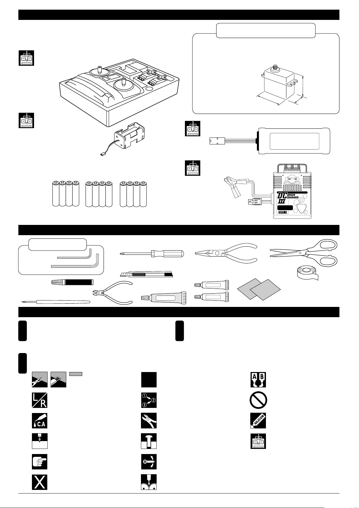
キットの他にそろえる物 REQUIRED FOR OPERATION
2チャンネル 2サーボ無線操縦機(プロポ)と電池ボックス
2 channel & 2 servo radio for R/C models, and battery box.
●このキットでは、フタバ製プロポを ベースに説明しています。
■スティックタイプ2チャンネルプロポ
Stick-type 2 channel radio
■電池ボックス
Battery Box
●プロポセットに付いている
ときは必要ありません。
If already supplied with the radio,
there is no need to purchase a
battery box separately.
■単3乾電池(送信機用)…8
AA-size Batteries
(For Transmitter) … 8 pcs.
AAAA
*プロポの取扱い方は、プロポに付属の説明書を参考にしてください。
For proper radio handling, refer to its manual.
(受信機用)…4
AA-size Batteries
(For Receiver) … 4 pcs.
AAAA
AAAA
標準以外のプロポを使用する場合
With a standard radio
●お手持ちのプロポを使用される場合は、下記の
<使用できるサーボ・サイズ>を確認してください。
If using a radio you are in possession of, check the dimensions
of its servos against the diagram below.
<使用できるサーボサイズ>
< Suitable servo dimensions >
36mm以下
under 36mm
40.5mm以下
under 40.5mm
■7.2Vニカドバッテリー
7.2V Ni-Cd Battery
■DC急速充電器
DC CHARGER
FUSE 7.5A
WARNING HOT
Ni-Cd BATTERY
WARNING HOT
7.5
DELTA PEAK AUTO-CUTOFF
E
CHARG
ART
ST
20mm以下
under 20mm
組立てに必要な工具 TOOLS REQUIRED
キットに入っている工具
TOOLS INCLUDED
■六角レンチ
Hex Wrench
■瞬間接着剤
Instant Glue
■キリ
2mm
Awl
1.5mm
■ニッパー
Wire Cutters
■+ドライバー(大、中、小)
Phillips Screwdriver (L.M.S)
■カッターナイフ
Sharp Hobby Knife
■シリコンシール剤
Silicon Sealant
SILICON
組立て前の注意(1) BEFORE YOU BEGIN (1)
組立てる前に説明書を良く読んで、おおよその
1
構造を理解してから組立てに入ってください。
Read through the manual before you begin, so
you will have an overall idea of what to do.
説明書に使われているマーク
3
Symbols used throughout the instruction manual, comprise:
をカットする。
Cut off shaded portion.
左右同じように組立てる。
Assemble left and right sides the
same way.
2セット組立てる(例)。
Assemble as many times as specified
(here: twice).
x2
番号の順に組立てる。
Assemble in the specified order.
■ラジオペンチ
Needle Nose Pliers
■エポキシ接着剤
Epoxy Glue
Epoxy A
Epoxy B
■サンドペーパー
Sand Paper
■ハサミ
Scissors
■テープ
Tape
●No.94752
防水クリアテープ
又はビニールテープ
Water-proofing Tape,
or Vinyl Tape
セットの内容をお確かめください。万一不良、不足があ
2
りましたら、お買い求めの販売店にご相談いただくか、
当社「ユーザー相談室」までご連絡ください。
Check all parts. If you find any defective or missing parts,
contact your local dealer or our Kyosho Distributor.
エポキシ接着剤で接着する。
Apply epoxy glue.
禁止事項(してはいけないこと)。
Do not do that!
瞬間接着剤で接着する。
Apply instant glue (CA glue, super glue).
2mmの穴をあける(例)。
Drill holes with the specified diameter
(here: 2mm).
2mm
注意して組立てる所。
Pay close attention here!
別購入品
Must be purchased separately!
余分をカットする。
Cut off excess.
仮止め。
Tentatively tighten.
可動するように組立てる。
Ensure smooth non-binding movement
while assembling.
グリスを塗る。
Apply grease.
シリコンシール剤を充てんする。
Fill in with Silicon Sealant.
コンプリートセットには含まれています。
それ以外は別購入品。
Only supplied with complete sets.
Must be purchsed separately with other sets.
2
Page 3
組立て前の注意(2) BEFORE YOU BEGIN (2)
このキットには、形のちがうビスや長さがちがうビス
4
が多く入っています。原寸図で確かめてから組立てて
ください。ビス類は多めに入っているものがあります
ので、予備としてお使いください。
This kit contains many screws in and other hardware
different metric sizes and shapes. For your reference,
the figures in the manual show actual sizes. (Some
screws are extras.)
●ビスの種類 Types of screws:
ビス Screw セットビス
●サイズ例
How size of screw is given:
3x12mmビス
Screw
TPビス
Self-tapping (TP) Screw
3mm
12mm
Set Screw
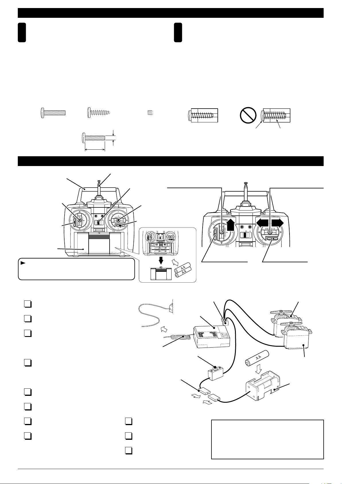
プロポの準備 RADIO PREPARATION
ハンドル
Handle
スピードコントロール
スティック
Speed Control Stick
CH-2 CH-1
スピードコントロール
トリム
Speed Control Trim
BATT.
アンテナ
Antenna
電源スイッチ
Switch
ラダースティック
Rudder Stick
ラダートリム
Rudder Trim
5
スピードコントロール
スティック
Speed Control Stick
●前進、停止の操作は
このスティックでお
こないます。
For forward move ment & stop.
CH-2 CH-1
BATT.
TPビスは、部品にネジを切りながらしめつけるビス
です。しめこみが固い場合がありますが、部品が確実
に固定されるまでしめこんでください。ただし、しめ
すぎるとネジがきかなくなりますので、部品が変形す
るまでしめないでください。
Self-tapping (TP) screws cut threads into the parts
when being tightened. Excessive force may
permanently damage parts when tightening TP
screws. It is recommended to stop tightening when
the part is securely attached or when some resistance
is felt after the threaded portion enters the plastic.
しめすぎ
Overtightened.
CH-2 CH-1
前
BATT.
進
ビスがきかない
The threads are stripped.
ラダースティック
Rudder Stick
●左右へ曲がるときの操
作はこのスティックで
おこないます。
For steering (left and
right bends).
左 右
バッテリーカバー
Battery Cover
ラダー側のリバーススイッチをリバースにし
てください。
Switch the rudder reverse switch (transmitter).
●プロポを下の順番にしたがってセットします。
Set up a radio control system as indicated below.
各コネクターを接続する。
1
Plug in connectors.
単3乾電池をセットする。
2
Install the AA-size batteries.
送信機のアンテナを最後まで引き出す。
3
縮めて使用すると電波の到達距離が短く
なるので注意する。
Extend the transmitter antenna. If not, the
range of the transmitter will not be sufficient!
受信機のアンテナをほどく。
4
縮めて使用すると電波の到達距離が短く
なるので注意する。
Undo the receiver antenna. If not, the
range of the receiver will not be sufficient!
送信機の各トリムレバーを中央にする。
5
Center all trims. (Transmitter)
送信機のスイッチを入れる。
6
Switch on. (Transmitter)
受信機のスイッチを入れる。
7
Switch on. (Receiver)
送信機のスティックを操作しサーボが
8
作動するか確認する。
Check that the servos move according
to your inputs. (Transmitter)
受信機のスイッチを切る。
9
Switch off. (Receiver)
送信機のスイッチを切る。
10
Switch off. (Transmitter)
送信機のアンテナを縮める。
11
Retract the antenna. (Transmitter)
アンテナ
Antenna
コネクター
Connector
受信機
Receiver
スイッチ
Switch
スピードコントロールトリム
Speed Control Trim
●船が走り出さないように
このトリムで調整します。
Adjust so boat will not
speed off at once.
コネクター
Connector
CH.1
BATT
ラダートリム
Rudder Trim
●船がまっすぐ走るように
このトリムで調整します。
For adjusting straightline
running.
スピードコントロールサーボ
Speed Control Servo
CH.2
プロポセットに付属している取扱説明書も
あわせてお読みください。
In addition to this page, read the instruc-tion
manual supplied with your radio as well.
ラダーサーボ
Rudder Servo
電池ボックス
Battery Box
3
Page 4
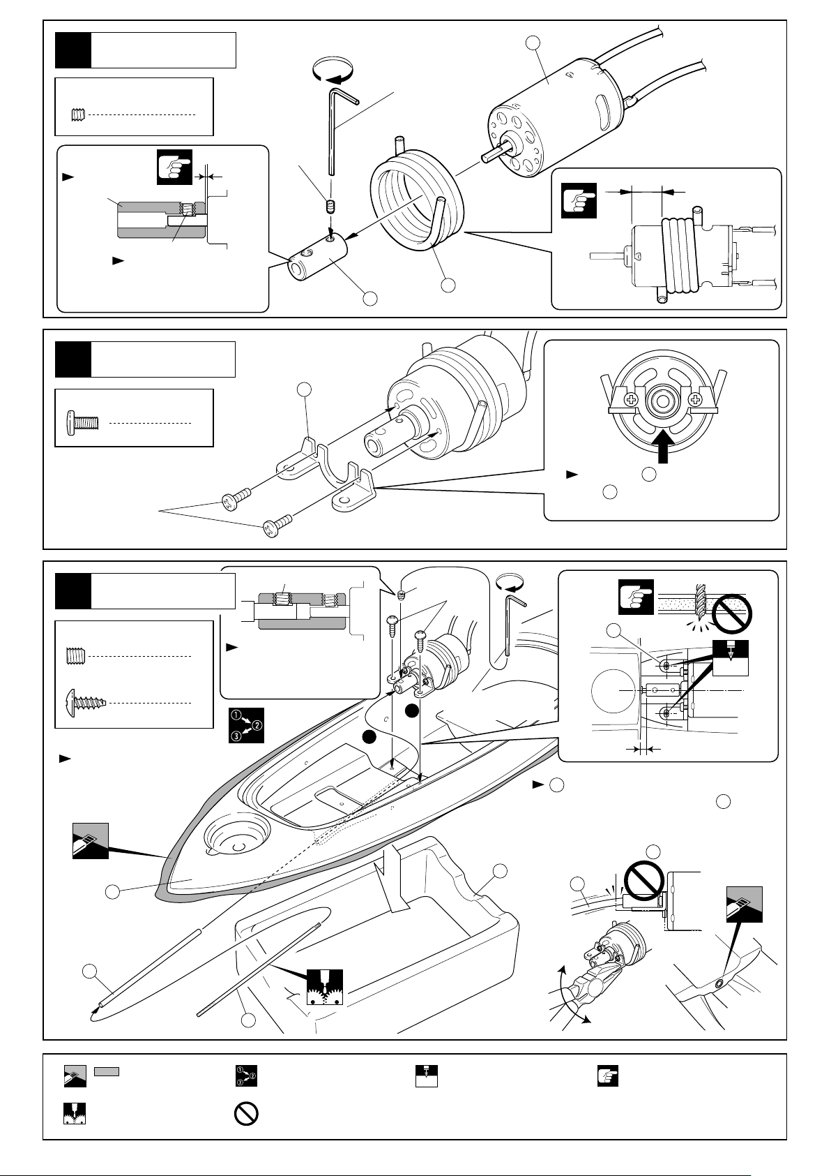
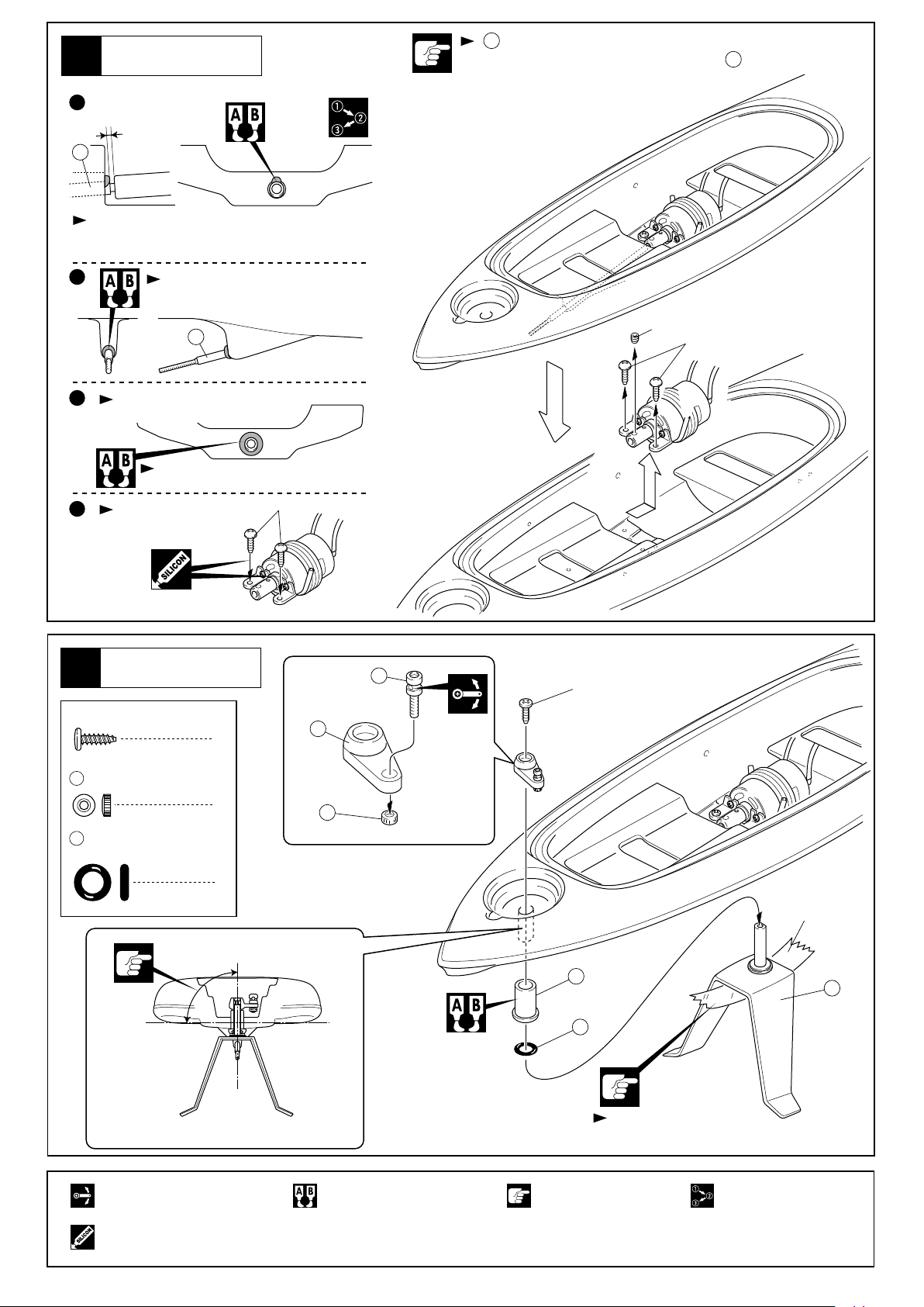
モーター
1
Motor
3 x 3mm
Set Screw
セットビス
1
六角レンチ(1.5mm)
Hex Wrench (1.5mm)
1
向きに注意。
Note the direction.
平らな面にセットビスを
固定する。
Firmly tighten the set screw
onto the flat spot.
モーター
2
Motor
3 x 6mm
Screw
ビス
3x6mm
3x3mm
2
0.2mm
3x3mm
4
15mm
2
3
矢印の方向に を押しながら固定する。
Push in the direction shown by the arrow.
Tighten the screws to hold it in place.
4
4
船体
3
Hull
4 x 4mm
セットビス
Set Screw
3 x 8mm
TP Screw
TPビス
カット後すきまがある場合
エポキシ接着剤を流す。
Add epoxy glue to parting
line if it appears after
debarring.
5
6
4x4mm
4x4mm
3x8mm
4
1
2
平らな面にセットビスを
固定する。
Firmly tighten the set screw
onto the flat spot.
六角レンチ(2mm)
2
Hex Wrench (2mm)
2mm
1
3mm
に無理な力がかからないように調整する。
7
In case the motor and drive shaft do
not connect straight, remove the 3 x 8mm
TP screws and adjust the angle of the motor
mount by using pliers, and/or enlarge the
hole for stern tube .
6
7
48
7
7
斜線部をカットする。
Cut off shaded portion.
グリスを塗る。
Apply grease.
番号の順に組立てる。
Assemble in the specified
order.
禁止事項(してはいけないこと)。
Do not do that!
2mmの穴をあける(例)。
Drill holes with the specified
2mm
diameter (here: 2mm).
注意して組立てる所。
Pay close attention here!
4
Page 5
船体
4
Hull
1
0.5mm
6
位置を合わせ、上の方だけ接着し仮固定する。
Confirm the position of the drive unit, temporarily glue
the end of the stern tube to the board.
2
防水のためすき間をなくす。
Ensure no space remains for waterproof.
6
のまわりにすき間があると浸水の原因となるので注意する。
Make sure no space remains around stern tube to prevent water entry.
6
3
モーターを外す。
Remove the Motor.
防水のためすき間をなくす。
Ensure no space remains for waterproof.
4
再びモーターを取付ける。
Reinstall the Motor.
ラダー
5
Rudder
2.6 x 8mm
TP Screw
TPビス
6
3x8mm
8
1
10
2.6x8mm
4x4mm
3x8mm
9
2mm
ナット
Nut
12
Oリング P5
O-ring P5
可動するように組立てる。
Ensure smooth non-binding
movement while assembling.
シリコンシール剤を充てんする。
Fill in with Silicon Sealant.
90°
1
1
9
テープ
Tape
11
13
12
接着剤が硬化後テープを外す。
After the epoxy glue gets hard, remove the tape.
エポキシ接着剤で接着する。
Apply epoxy glue.
注意して組立てる所。
Pay close attention here!
番号の順に組立てる。
Assemble in the specified
order.
5
Page 6
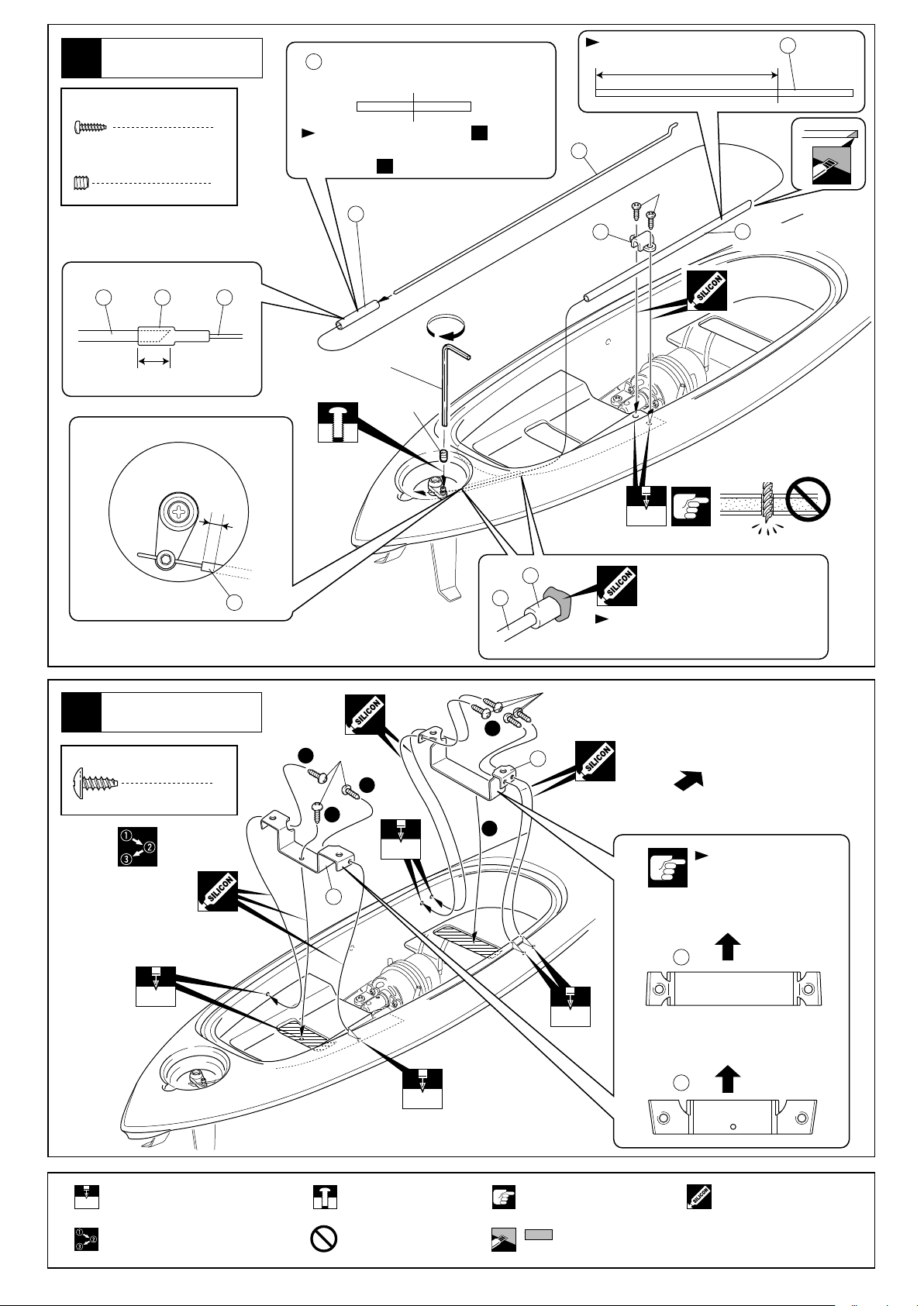
船体
6
Hull
2 x 6mm
TP Screw
3 x 3mm
Set Screw
TPビス
セットビス
カットする。
15
14
Cut.
200mm
2x6mm
16
シリコンチューブ(細)
17
Silicone Tube (thin)
2
1
半分にカットする。残りは で使用。
Cut silicon tube in half. The rest is used
at process .
25
シリコンチューブ(細)
17
Silicone Tube (thin)
25
P.Pパイプ
16
PP Pipe
P.Pパイプ200mm
PP Pipe
1716
10mm
船体
7
Hull
3 x 8mm
TP Screw
TPビス
15
4mm
7
六角レンチ(1.5mm)
Hex Wrench (1.5mm)
16
2
3x8mm
3x3mm
2
1mm
16
15
防水のためすき間をなくす。
Ensure no space remains for waterproof.
3x8mm
4
18
前部
Front
2mm
2mmの穴をあける(例)。
Drill holes with the specified
2mm
diameter (here: 2mm).
番号の順に組立てる。
Assemble in the specified
order.
1
2mm
19
2mm
仮止め。
Tentatively tighten.
禁止事項(してはいけないこと)。
Do not do that!
3
注意して組立てる所。
Pay close attention here!
斜線部をカットする。
Cut off shaded portion.
2mm
向きに注意
Note the direction.
前部
Front
18
前部
Front
19
シリコンシール剤を充てんする。
Fill in with Silicon Sealant.
6
Page 7

船体
8
Hull
21
防水のためすき間を
なくす。
Ensure no space remains
for waterproof.
15mm
シリコンチューブ(太)35mm
Silicone Tube (thick)
シリコンチューブ(太)180mm
Silicone Tube (thick)
20
21
22
20
シリコンチューブ(太)
20
Silicone Tube (thick)
180mm 50mm
カットする。
Cut.
5mm
22
防水のためすき間をなくす。
Ensure no space remains for
waterproof.
9
10
ハッチ
Hatch
船体
Hull
23
24
25
スポンジテープ
26
Sponge Tape
23
25
スポンジテープ
26
Sponge Tape
24
Oリング38mm
O-ring
薄く塗る。
Apply grease thin.
向きに注意。
Note the direction.
防水のためすき間をなくす。
Ensure no space remains for
waterproof.
エポキシ接着剤で接着する。
Apply epoxy glue.
瞬間接着剤で接着する。
Apply instant glue (CA glue, super glue).
グリスを塗る。
Apply grease.
注意して組立てる所。
Pay close attention here!
7
Page 8

メインハッチ
11
Main Hatch
3 x 12mm
F/H Screw
サラビス
中心に貼る。
Apply decal to be centered
on the board.
デカール
Decals
2
18
18
27
3
デカール
Decals
21
3
2
1
デカールを の順で貼る。
Apply the decals , and
in this order.
18 21
4
18 21
プロポ
12
Radio
28
3mm
グロメット
Grommet
1
30
Oリング P2
O-ring P2
1
12
Oリング P5
O-ring P5
1
4
37
28
<OFF>
<ON>
28
デカール
Decals
3
32
2mm
カット後すきまがある場合
エポキシ接着剤を流す。
Add epoxy glue to parting
line if it appears after
debarring.
27
31
2
12
スイッチ
Switch
向きに注意。
Note the direction.
30
12
31
37
37
29
4
3x12mm
30
ON
1
OFF
船体
13
Hull
5 x 15mm
Screw
12
5mm
Washer
ビス
Oリング P5
O-ring P5
ワッシャ
スイッチに付属のビス。
33
がつぶれすぎない程度に締め込む。
12
Screw 5 x 15mm screws paying attention not to squeeze too much.
12
4
5x15mm
4
5x15mm
12
Supplied with the switch.
12
ビニールテープ等でふさぐ。
Close up antenna hole with vinyl
tape.
5x15mm
12
37
5mm
x4
12
4
番号の順に組立てる。
Assemble in the specified
order.
シリコンシール剤を充てんする。
Fill in with Silicon Sealant.
斜線部をカットする。
Cut off shaded portion.
2セット組立てる(例)。
Assemble as many times as specified
x2
(here: twice).
瞬間接着剤で接着する。
Apply instant glue (CA glue,
super glue).
禁止事項(してはいけないこと)。
Do not do that!
2mmの穴をあける(例)。
Drill holes with the specified
diameter (here: 2mm).
コンプリートセットには含まれています。
それ以外は別購入品。
Only supplied with complete sets.
Must be purchsed separately with other sets.
注意して組立てる所。
Pay close attention here!
8
Page 9

14
15
x2
船体
Hull
一度組立て全体に水をかけて内部に浸水しないかテストする。
Assemble the hatch and give a leak test by submerging board under water.
テストが終わったら水をよくふき取りを外しておく。
After the test, dry the board and remove .
37
37
プロポ
Radio
両面テープ
35
サーボ
Servo
Double-sided Tape
40mm
10mm
10mm
カットする。残りは で使用。
Cut off as above. The rest is used at
process .
17
17
10mm
37
34
両面テープ
35
Double-sided Tape
36
10x20mm
サーボのつぎ目まわりに京商製防水クリア
テープ(No.94752¥450)又はビニール
テープを貼り、コードの出口にシリコンシ
ール剤を塗っておくとより防水効果が向上
します。
For more water-proofing, apply Kyosho
water-proofing tape (No.94752) or vinyl
tape around the connection of servo, and
silicon sealant around the root of the cords.
プロポ
16
Radio
20mm
オフ
OFF
オン
ON
スピードコントロールサーボ
Speed control servo
スピードコントロールスティック 中立
With the speed control stick in neutral.
0.5mm
スピードコントロールスティック 前進
With the speed control stick pushed up.
35
両面テープ
Double-sided Tape
40x10mm
斜線部をカットする。
Cut off shaded portion.
コンプリートセットには含まれています。
それ以外は別購入品。
Only supplied with complete sets.
Must be purchsed separately with other sets.
サーボ付属
Supplied with the servo
注意して組立てる所。
Pay close attention here!
0.5mmのすき間が出来るようにする。
Ensure a gap of 0.5mm.
2セット組立てる(例)。
Assemble as many times as specified
x2
(here: twice).
シリコンシール剤を充てんする。
Fill in with Silicon Sealant.
9
Page 10

プロポ
17
Radio
両面テープ
35
Double-sided Tape
10mm
10mm
40mm
カットする。
Cut.
位置を合わせて固定。
Adjust the position.
プロポ
18
Radio
両面テープ
35
Double-sided Tape
40mm
40mm
カットする。
Cut.
ラダーサーボ
Rudder servo
90°
2
この穴を使う。
Use this hole.
11mm
サーボ付属
Supplied with
the servo
位置を合わせて固定。
Adjust the position.
1
15mm
10
斜線部をカットする。
Cut off shaded portion.
注意して組立てる所。
Pay close attention here!
コンプリートセットには含まれています。
それ以外は別購入品。
Only supplied with complete sets.
Must be purchsed separately with other sets.
番号の順に組立てる。
Assemble in the specified
order.
Page 11

プロポ
19
Radio
コネクターをつなぐ。
Plug in.
パーツの
入っていた袋
Part bag
テープでしばる。
Bind with tape.
向きに注意
Note the
direction.
プロポ
20
Radio
電池ボックス
Battery Holder
パーツの入っていた袋
Part bag
受信機
Receiver
コネクターをつなぐ。
Plug in.
90°
角度を合わせセットビスを締め込む。
Adjust the angle as shown, and then tighten
the set screws.
90°
21
人形
Figure
38
斜線部をカットする。
Cut off shaded portion.
カット後すき間がある場合、エポキシ接着剤を流す。
Add epoxy glue to parting line if it appears after debarring.
コンプリートセットには含まれています。
それ以外は別購入品。
Only supplied with complete sets.
Must be purchsed separately with other sets.
39
注意して組立てる所。
Pay close attention here!
40
11
Page 12

22
人形
Figure
41
船体
23
Hull
3mm
ナイロンナット
Nylon Nut
8mm
42
42
40
38
39
1
43
47
ニカドバッテリー
24
Ni-Cd Battery
7.2Vニカドバッテリー
走行時のみコネクターを
つなぐ。
Connect the cords only
when running the boat.
エポキシ接着剤で接着する。
Apply epoxy glue.
Ni-Cd Battery
注意して組立てる所。
Pay close attention here!
マジックテープ
44
Magic Tape
マジックテープ
44
Magic Tape
40mm
マジックテープ
44
Magic Tape
40mm
コンプリートセットには含まれています。
それ以外は別購入品。
Only supplied with complete sets.
Must be purchsed separately with other sets.
50mm
カットする。
Cut.
50mm
マジックテープ
44
Magic Tape
12
Page 13

メインハッチ
25
Main hatch
45
Oリング S22.4
O-ring S22.4
45
六角レンチ(1.5mm)
45
Hex Wrench (1.5mm)
45
2
1
1
46
メインハッチ
26
Main hatch
5 x 15mm
Screw
12
ビス
Oリング P5
O-ring P5
2
4
2
シリコンチューブ(細)
Silicone Tube (thin)
17
PPパイプ
PP Pipe
16
250mm
5x15mm
12
5x15mm
12
5x15mm
12
コード類をはさまない様注意する。
Set the hatch, paying attention not
to catch the cords under seal edge.
がつぶれすぎない程度に締め
12
込む。
Screw 5 x 15mm screws paying attention
not to squeeze too much.
12
12
OリングP5
4
17
10mm
16
PPパイプ
PP Pipe
250mm
12
5x15mm
カットする。
Cut.
12
11
17
番号の順に組立てる。
Assemble in the specified
order.
16
18 20 19 17
18 20 19 17
1
3
14
10
16
8
6
5
15
7
2
13
20
注意して組立てる所。
Pay close attention here!
18
9
19
20
禁止事項(してはいけないこと)。
Do not do that!
斜線部をカットする。
Cut off shaded portion.
13
Page 14

取扱いの注意 OPERATING YOUR MODEL SAFELY
事故やケガ等の危険防止のため、次のことを必ずお守りください。
In order to avoid accidents and personal injury, be sure to observe the following:
●波の動きに注意し、操縦時には水に入らない。
Pay attention to the waves and operate your board from shore.
Always keep model in sight,and within 20m--from shore.
●15才以下の方は保護者といっしょに遊んでください。
Enjoy your R/C Surfer with your guardian/protector if you are
under 15 years old.
●R/Cボートは、湖や河川などの水辺で楽しむものです。
操縦する方や同行の方が思わぬ事故に合わないように
注意し、必ず安全な場所で走航させてください。
With R/C boats, discover a new world of pleasure.
Wheth-er you run your boat on lakes, rivers or elsewhere, take precautionary measures to avoid accidents.
●ケガの恐れがあるので回転
部分に手や物を入れないよ
うにしてください。
Do not put your hands or
any objects into rotating
parts, as this could result in
serious accidents!
●走航直後はモーターやニカ
ドバッテリーなど熱くなっ
ているのでしばらくさわら
ない。また、連続走航はさ
せない。
ery
Ni-Cd
tt
Ba
V
.2
7
The motor and Ni-Cd
battery get hot from run-ning. Do not touch them
for a while after running.
●充電 中は、 ニカド バッテ
リー、充電器ともに発熱す
るので燃えやすい物の上で
の充電は火災等、事故の恐
B
ATTERYBATTER
Y
れがありますのでおやめく
ださい。
Never put the charger and Ni-Cd battery near flam-mable material while charging as this may cause fires!
●次のような場合ショートの原因となり火災等事故の恐
れがあり非常に危険です。
Under the following circumstances, short circuits may
oc-cur and result in fires or other accidents:
■ニカドバッテリーの分解、改造は絶対にしない。
When disassembling or modifying Ni-Cd batteries.
Never do that!
●次のような時や、次のような場所では絶対に走航させ
ないでください。思わぬ事故やケガの原因となります。
For accident prevention, do not run your model under
the following circumstances:
強風や波浪等の注意報が出ているとき。
Operate your Kyosho R/C Surfer in waves under ..5m height. Do
not operate in heavy seas or when a storm warning is in force.
遊泳禁止の場所。(足場が不安定だったり潮の流れ
が速い場所)
Operate Kyosho R/C Surfer at lifeguard patrolled beachs, and in
signposted surfcraft areas only. Stay away from swimmers. Notify
the lifeguard of your presence,and follow his/her instructions.
人が多い場所。
Always be considerate of other beach users whilst using this
model.
河川が増水しているとき、また流れが速いとき。
When rivers are swollen or their current is strong!
同じバンドの無線操縦模型がそばにいるとき。
Also make sure that nobody is using the same
frequency as you do at the same time!
01
05
プロポの電池残量が少ないとき。
With weak radio batteries!
船の動きがおかしい???とき。
When the boat behaves or operates strangely!
?
?
?
?
?
P
OWER 1
4
0
7.
0
2V
破裂危険
EXPLOSIVE
■ニカドバッテリーは有害重金属が使用されています。
火中に投げ入れて破裂すると非常に危険ですので、絶
対にしない。
Never dispose of Ni-Cd batteries into a fire, as these
can explode or emit noxious gases from heavy met-als
used in Ni-Cd batteries !
7
7
.
.
2
2
N
N
V
V
i-C
i-C
d B
d B
att
att
er
er
y
y
破裂危険
EXPLOSIVE
14
●走航させない時は、必ず電源スイッチを
『OFF』にし、安全のため必ずニカドバ
ッテリーのコネクターを抜き、本体より
外しておく。
発熱、発火の原因になります。
When NOT using the model, always
switch off the receiver and transmitter!
Furthermore, disconnect the Ni-Cd
確認する
CHECK
battery and remove it from the model!
This may lead to overheat and fires!
●不要になったニカドバッテリーは捨てずに販売店にお
戻しください。
Do not dispose of Ni-Cd batteries! Return them to the
retail shop!
Page 15

走行前のチェック PRE-RUN CHECKLIST
ゆるんでいるビスはありませんか。
プロポの電池はありますか。
ニカドバッテリーの充電はしていますか。
ラダーの動きはプロポの動きとあってますか。
スピードコントローラーの動きはプロポの動き
とあってますか。
走航場所は安全な所ですか。
近くで同じバンドで無線操縦模型をしている人は
いませんか。
ニカドバッテリーは確実に固定されていますか。
スクリューのとりつけは確実ですか。
回転部分にはグリスが塗ってありますか。
可動部分に当たる物はありませんか。
走航手順 PROPER OPERATING PROCEDURES
走航用のバッテリーを充電。
Fully charge the Ni-Cd battery.
送信機の電池をチェック。
Check the transmitter batteries
CH-2 CH-1
BATT.
Are all screws securely tightened?
Are the radio batteries fully charged?
Is the Ni-Cd battery fully charged?
Does the rudder operate according to your inputs
on the transmitter?
Does the speed controller operate according to your
inputs on the transmitter?
Is the Ni-Cd battery securely attached?
Is the running area safe?
Is nobody on your frequency when running at the
same time in the same area?
Is the propeller securely attached?
Are all rotating parts greased?
Can all moving parts move freely, without binding?
スピードコントローラーがオフであるこ
31 2
とを確認。
Ensure that the speed control servo is in
ぬれた手でプロポに
触れない。
Keep radio handset dry
at all times.
off position.
ニカドバッテリーのコネクターをつなぐ。
4
Connect the Ni-Cd battery.
受信機のスイッチを入れる。
7
Switch on the receiver
ON
走航場所が安全であることを確認。
10
Make sure the running area is safe.
船を回収する。
1
After finishing running, collect your
boat.
送信機のアンテナをのばす。
5
Extend the transmitter antenna
C
H
-
2
BA
TT
.
C
H
-
1
ラダーがプロポのスティックの
8 9
動きとあっているか確認。
Make sure the rudder operates according
to your inputs on the transmitter.
CH-2 CH-1
BATT.
左 右
送信機のスイッチを入れる。
6
Switch on the transmitter.
スピードコントローラーがプロポの
スティックの動きとあっているか確認。
Make sure the speed controller operates
according to your inputs on the transmitter.
前
進
CH-2 CH-1
走行が終わったら AFTER RUNNING . . .
受信機のスイッチを切る。
2
Switch off the receiver.
送信機のスイッチを切る。
3
Switch off the transmitter.
BATT.
CH-2 CH-1
OFF
ON
BATT.
ON
OFF
船体の汚れ水分をきれいにとる。
4 5
Remove dirt from the hull.
船体内部に水や砂が入らない様注意する。
Avoid getting sand or water onto board interior
whilst changing batterys.
OFF
ニカドバッテリーのコネクター
をはずす。
Disconnect the Ni-Cd battery.
CH-2 CH-1
BATT.
OFF
ON
●走航させない時は、必ず電源スイッチを『OFF』
にし、安全のため必ずニカドバッテリーのコネク
ターを抜き、本体より外しておく。
発熱、発火の原因になります。
When NOT using the model, always
switch off the receiver and transmitter!
Furthermore, disconnect the Ni-Cd
battery and remove it from the model!
This may lead to overheat and fires!
確認する
CHECK
15
Page 16

波乗りのコツ HOW TO SURF
RC サー ファ ーの 操縦 方法 は、 普通 のR /C ボー ト と 同 じ で す が 波 に 上 手 く乗 るに は、 波を 読み タイ ミン グを
合わ せ る 事 が ポ イ ン ト で す 。 安 全 に 注 意 し 練 習 し て く だ さ い 。
En j o y y o u r K y o s h o R / C S u r f e r o n t h e p r i n c i p l e o f s a f e t y f i r s t .
St e e r R / C S u r f e r t h r o u g h s u r f i n s i m i l a r w a y t o R / C b o a t s .
STEP:1リリースLAUNCHING R/C SURFER.
RC サ ー フ ァ ー を 海 面 に 離 す 時 と 回 収 す る時
が、 操 縦 者 の あ な た が 海 面 に 最 も 近 づ く 時
です 。 波 に 足 を す く わ れ た り し な い よ う 、
安全 の 為 に 周 囲 の 状 況 を 良 く 確 認 し て く だ
さい。
波が 遠 く に あ る 時 で 、 海 面 が 引 き 始 め た 時
にRC サ ー フ ァー を 押 し 出す 。 ( リ リー ス )
ぬれた手でプロポに触れない。
When launching, pay attention to oncoming
waves, to avoid falling in the water and wetting
the transmitter.
Launch R/C Surfer by placing into water during
flattest conditions between "sets"of waves.
Motor R/C Surfer out past small waves close to
shoreline.
Keep radio handset dry at all times.
引く波に合わせてモーターON
Motor R/C Surfer out past small
waves close to shoreline.
STEP:2沖へ進むGETTING "OUT THE BACK" OF THE WAVES.
途中 の 波 は 、 波 の 正 面 に 向 か い 真 っ 直 ぐ 通
過 。 ( 横 向 き で は 、 転 倒 し た り 岸 に 押 し 戻
された り す る 。)
岸から 2 0 m 以上 離 れ な い。
Choose the easiest path out through the surf,
paying attention to avoid being hit by breaking
waves. Jump broken waves "whitewash"
straight on, and try to steer towards the
unbroken parts of the waves "shoulder".
Position R/C Surfer behind breaking wave area
"impact zone" for best wave selection.Operate
R/C surfer from beach away from shoreline.
keeping the model within 20m of operator.
STEP:3波待ちWAITING "OUT THE BACK" FOR THE GOOD WAVE.
岸に向 か い 待 機。
When in position "out the back", point the R/C
Surfer towards shore, paying attention not to
get "caught inside", of oncoming breaking
waves. Try not to waste battery power whilst
waiting for wave.
OK
20m
STEP:4波に乗るCATCHING AND RIDING A WAVE.
乗り た い 波 が ボ ー ド に 近 づ き 、 ボ ー ド の 後
端が押 し 上 げ られ た ら モ ータ ー O N 。
波の ス ピ ード に あ わせ 、 モ ータ ー O N/ O F Fで
スピー ド 調 整 。
真っ 直ぐ岸に 向かう走 行に慣れ たら、ラ ダ ー
の操 作 も 併 用 し さ ま ざ ま な ラ イ デ ィ ン グ に
チャレ ン ジ
When your selected wave begins to lift the tail
of the R/C Surfer, switch motor power on to
"take off". Adjust the speed of the R/C Surfer to
match the speed of the wave by using motor
switch on/off "stalling". After you have
mastered surfing straight to shore, begin
experimenting using rudder control to surf
across the waves "cornering".
STEP:5再び沖へCORNERING AND GETTING OFF WAVES.
波が く ず れ 始 め た ら 、 モ ー タ ー O N で 波 の前
に出て タ ー ン でき る ス ペ ース を 確 保 。
沖に 向 か い タ ー ン し 、 乗 っ て き た 波 の 正 面
に向か い 真 っ 直ぐ 通 過 。
スピードが 落ちてき たら早 めにRC サーファー
を回収 す る 。
回収 時 に プ ロ ポ を 濡 ら さ な い よ う に 注 意 す
る。
回収 し た ら 砂 や 海 水 を 良 く ふ き と り 、 ニ カ
ドバッ テ リ ー をは ず す 。
Cornering is the starting point for advanced R/C
surfing. When the R/C Surfer has "taken off" and is
very close to the bottom of the wave, gently turn the
R/C Surfer "bottom turn" in required direction, paying
attention to the falling "lip". Stop "bottom turn" when
the R/C Surfer is surfing straight across the wave.
When desired length of ride is reached, or the wave
threatens to "dump" on the shoreline, another
"bottom turn" will direct the R/C Surfer over the back
of the wave "flicking off". Allways try to "flick off" to
avoid being "dumped" on shore by "closeout".
Use step (2) to get "out the back" again.
Pay attention to when the R/C Surfer begins to slow
down, as battery power gets low. When this begins to
happen, surf R/C Surfer closer to shore to be easily
retrieved. Save enough battery power to motor into
shore to avoid being caught "out the back" with no
power. Catch small wave straight to shore. Hold
transmitter high when retrieving R/C Surfer from surf.
Once retrieved, wash sand off R/C Surfer, and dry
well before battery removal/change.
ON
ON
16
Page 17

日常の整備 EVERYDAY MAINTENANCE
ねじ、ナットのゆるみ、老化をチェック。
回転部分にはグリスを塗っておく。
コードが可動部分にこすれたりして破損している
ときは修理する。
サーボのコードや受信機のアンテナ線が破損して
いるときは、使用しているプロポメーカーに修理を
依頼する。
部品が摩耗または破損していないかチェック。
船体の汚れをとる。
船体に入っている水をよくふき取り、よく乾かす。
金属部品にオイルを塗る。
故障かなと思う前に
症 状
スピードコントロールサーボが
動かない。
モーターがまわらない。
原 因
送信機の電池がない。
配線をまちがえている。
ニカドバッテリーの容量不足。
配線をまちがえている。 説明書をよく読んで配線する。
コネクターの接触不良。
モーターの故障。 モーターを交換する。
Make sure screws and nuts are securely tightened
and other parts are not worn.
Grease all rotating parts.
Repair the wiring should cords be damaged or drag
into rotating parts.
Should servo cords and the receiver antenna be
damaged, return them to the manufacturer for repair.
Make sure all parts are neither worn nor damaged.
Remove dirt from the hull.
Draw out water from inside the hull.
Oil the metal parts.
対 策
送、受信機のスイッチを入れる。送、受信機のスイッチがはいっていない。
新しいものに交換する。
プロポの説明書をよく読んでコネクターを
接続する。
ニカドバッテリーを充電する。
コネクターのはめこみをきつくする。
モーターはまわるが走らない。
スクリューを手でまわすと重い
またはまわらない。
スピードコントロールスティ
ックをはなしても船がとまら
ない。
ジョイントがついていない。
または、ビスがゆるんでいる。
回転部分にゴミやホコリがつまっている。
リンケージの調整不良。 プロポのトリムで調整する。
PROBLEM CAUSE
Speed control servo does
not operate.
Motor does not rotate.
Transmitter batteries are weak.
Improper radio installation.
Ni-Cd battery capacity is insufficient.
Improper radio installation. Correct as per instruction manual.
Loose connectors.
Motor trouble. Replace with new motor.
ジョイントを止めているビスを
しめる。
ゴミやホコリを取り除きグリスを塗っておく。
このとき、全開に入らないようなら説明書
を読んでリンケージをもう一度調整する。
TROUBLESHOOTING
REMEDY
Switch on.Transmitter and/or receiver is not switched on.
Replace with new batteries.
Correct as per radio instruction
manual.
Recharge Ni-Cd battery.
Make connectors tighter (e.g. with
minus screwdriver).
Motor rotates but boat will not run.
When rotating by hand, propeller
feels heavy or does not rotate.
Even when releasing speed
control, boat will not stop.
Joint is not installed.
Or, screws are loose.
Dirt entered rotating parts. Clean and regrease.
Improper linkage adjustment. Adjust speed control trim on transmitter.
Tighten screws holding joint.
Should speed controller not return to
neutral, readjust linkages as per instruction manual.
17
Page 18

スペアパーツ SPARE PARTS
品番 パーツ名 内容(キーNo.と入数) ★定価
No. Part Names
ボード本体
SF-1
Surf Board
ハッチセット
SF-2
Hatch Set
Description
(Key No. & Qty.)
5 18 19
x1
11 23 24 25 37 x1
7500 200
2500
★発送
手数料
(一律)
*FOR JAPANESE MARKET ONLY.
品番 パーツ名 内容(キーNo.と入数) ★定価
No. Part Names
モーターマウント
94722
Motor Mount
ウォータージャケットセット
94741
Water Jacket Set
Description
(Key No. & Qty.)
4
x1
2 20 21
x1
300 200
2000
★発送
手数料
(一律)
スタンド
SF-3
Stand
サーファー人形
SF-4
Figure
ラダーセット
SF-5
Rudder Set
リンケージセット
SF-6
Linkage Set
デカール
SF-7
Decal
5×15mmトラスビスセット
SF-8
5×15mm TH Screw Set
Oリングフック
SF-9
O-ring Hook
カラーシリコンチューブ
1790
Color Silicone Tube
マジックテープ
90497
Magic Tape
モータージョイント
94421
Motor Joint
スクリュー(D31xP1.4)
94427
Propeller (D31xP1.4)
ウォータージャケット
94441
Water Jacket
防水スポンジテープ
94450
Waterproof Sponge Tape
48
x1
38 39 40 41
10 13 14 36
8 9 15 16
デカール一式
Decal Set
5×15mmビス,5mmワッシャー x4
5×15mm Screw,5mm Washer x4
46
20
44
3
x1
43
2
x1
26
x1
x2
x2
x2
x2
x142 x2
27
x2
x1
x1
1500
4200
650
600
1200
200
200
400
300
200
800
1200
200
3mmグロメット
94855
3mm Grommet
シリコンOリング(P2)赤
94871
Silicone O-ring (P2) Red
シリコンOリング(P5)赤
94873
Silicone O-ring (P5) Red
防水レシーバースイッチホルダー
94881
Waterproof Switch Holder
吸排水パイプ
94955
Inlet & Outlet Pipe
Oリング(S22.4)
94975
O-ring (S22.4)
Oリング(S38)
94976
O-ring (S38)
スクリューシャフト(162mm)
94995
Propeller Shaft (162mm)
スポンジテープ(1mm)
96441
Sponge Tape (1mm)
モータースイッチ(S)
96551S
Motor Switch (S)
28
x5
30
x10
12
x5
12 29 30 31 32 33
21 22
x1
45
x5
24
x1
3 6 7 47
35
34
x1
x12
x1
x1
200
200
200
650
250
200
200
1000
300
900
キットの部品の一部にはスペアパーツとして販売してないものがあります。
京商ではオプションパーツを販売していますのでお買い求めください。
Some of the parts included are not available as spare parts.
Purchase optional parts instead.
オプションパーツ OPTIONAL PARTS
品番 パーツ名 内容 ★定価
No. Part Names Description
17
蛍光シリコンチューブ
1795
Fluorescent Silicone Tube
KP/KY
防水クリアーテープ
94752
Waterproofing Tape
と交換, 1ヶ入
Instead of 17 , 1pcs.
サーボ防水用
for Servo.
400 200
450
★発送
手数料
(一律)
*FOR JAPANESE MARKET ONLY.
品番 パーツ名 内容 ★定価
No. Part Names Description
TR-12
防水ゴム袋
Waterproofing Bag
受信機、電池ボックス用
for receiver & battery box.
★発送
手数料
150 200
18
Page 19

*発送手数料は2000年5月1日現在のものです
"KyoshoDirect‑Mail‑Parts‑Order‑System"isavailableonlyforJapanesemarket
京商スペアパーツ・オプションパーツの購入方法
これらの購入方法は日本国内に限らせていただきます
部品を
こわしちゃった
●部品をこわしたり、なくしてしまった場合でも
スペアパーツやオプションパーツを購入し、
元どおりに直す事ができます。
●パーツはお 店で直接購入していただくか、
お店に行けない場合は郵便を利用して京商
から通信販売で購入できます。
●京商では電話での直接のご注文は取り扱って
おりません。ご了承ください。
1.まずはお店でお求めください
まずは、お近くのお店か、この商品をお買い求めいただいたお店にご来店
下さい。ご希望のパーツの在庫があれば即購入できます。その際に組立/取
扱説明書をお持ちになると購入がスムーズになります。
お店で在庫切れの場合でも京商の『パーツ直送便』
※
でお店から京商へ申し込めます
購入方法による手数料、お届け日数のめやす
購入方法 発送手数料
お店で
お店に在庫がない場合は
パーツ直送便で
お
店
に
現金書留で
行
け
な
い
場
郵便振込で
合
※お届け 予定日 数は夏・冬期休 業また は交通事情等運 送上の 理由
により遅れる場合がございます。
不要
200
200
円
円
お届け予定日数
日
3〜4
日
6〜7
日
10〜12
お店でご希望のパーツがたまたま品切れだった場合でも、京商の『パーツ直送便』※を利用すればその場で注文できます。『パ
ーツ直送便』は、お店に備え付けのパーツ直送便注文用紙にご希望のパーツの品番や数量等、必要事項をご記入の上、お
店に代金をお支払いいただければ結構です。3〜4日でお客様のご自宅か、お店にお届けします。発送手数料が不要で早く
着くお得なシステムです。
※一部取り扱っていないお店もございます。
パーツ直送便
注文用紙に『品番』
と必要数を記入。
パーツ直送便取り扱い店は
このステッカーが目印
2.お店に行けない場合は
次の2つの方法で京商から通信販売で購入できます
パーツ直送便の
注文用紙といっしょに
代金をお店の人に
払おう!
お店に行けない場合は郵便局から申し込んでいただくようになります。
発送手数料
円
1
現金書留で京商へ申し込む
必要事項を記入した用紙と代金を現金書留に
て京商までご送金ください。代金は次のとおり
となります。
200
お届けまで
日
6〜7
2
郵便振込で京商へ申し込む
郵便局で払込用紙に必要事項をご記入のうえ
、代金を郵便振込にて京商までご送金くださ
い。代金は次のとおりとなります。
●代金は、スペアパーツの定価の他に発送手数料(一律200円)と消費税がかかります。
●代金の計算方法 代金=(スペアパーツの定価の合計+発送手数料200円)×消費税1.05(1円未満は四捨五入)
発送手数料は
不要
3〜4日でお客様の
ご自宅かお店に
お届けします。
発送手数料
円
200
郵便振込のほうが
現金書留より郵便料金が
安いね。
お届けまで
日
3〜4
お届けまで
10〜12
日
(1)
名
氏
電
郵便
話番
住
パー
(2)
号
号
番
所
ツ名
番
品
量
数
243 0034
神奈川県厚木市船子153
京商株式会社
ユーザー相談室
TEL.046-229-4115
(1)メモ用紙に 氏名・電話番号・郵便番号
住所(電話番号は登録・発送をスムーズに
するためのものです。必ずご記入ください)
と注文するパーツ名・品番・注文数を必ず
記入して、(2)お間違えのないよう代金と
いっしょに郵便局よりご送金ください。
・
《現金書留宛先》
〒243-0034 神奈川県厚木市船子153
京商株式会社 ユーザー相談室
Tel.046-229-4115
《払込用紙記入例》
(1)
払 込 取 扱 票 払込票兼受領証
00
口座番号 (右詰めにご記入ください)
※ ※
0 0 2 1 0 4 4 7 2 7 1
加
各
※
入
票
者
の
名
京 商 株 式 会 社
※
印
※
欄
は
品番 パーツ名 数量
通
払
込
(3)
1901 ベアリング 2
人
信
に
発送手数料
お
い
(例)
消費税
欄
合計
払
込
(郵便番号 )
※
人
住
所
氏
名
裏面の注意事項をお読みください。(郵政省)
(部品+発送手数料合計金額 x 5%)
(2)
て
記
載
し
て
く
だ
さ
い
金
額
料
金
(電話番号 - - )
千 百 十 万 千 百 十 円
1 6 8 0
殊 扱
特 取
1,400
200
80
1,680
(4)
受
付
局
日
附
印
(1)
※
口
0 0 2 1 0 4
座
番
号
※
加
切
記
※
入
り
載
者
取
事
名
ら
項
な
を
金
千 百 十 万 千 百 十 円
い
訂
※
で
正
額
郵
し
便
た
局
場
※
払
に
合
込
お
は
人
出
住
し
そ
所
く
の
氏
箇
だ
所
さ
名
に
い
訂
正
料
(消費税込み)
印
を
押
金
し
て
く
だ
さ
特殊取扱
い
右詰めにご記入ください
4 7 2 7 1
京商株式会社
1 6 8 0
(2)
受付局日附印
円
(1)口座番号 : 00210-4-47271
加入者名:京商株式会社
(2)あな たの 氏名・電話番号・郵便
番号・住所 を必ず記入してください。
(電話 番号 は登 録・発送をスムーズ
にするためのものです 。必ずご記
入ください)
(3)注文する、品番・パーツ名・注文
数を必ず記入してください。
(4)お間違えのないよう合計金額を
記入のうえ、ご送金ください。
京商株式会社
〒243-0034 神奈川県厚木市船子153
●お問い合わせはユーザー相談室まで Tel. 046-229-4115 受付時間 : 月〜金曜(祝祭日を除く)10:00〜18:00
Page 20

The servise mentioned below is available only for Japanese market.
組立や、操作上で不明な点のお問い合わせ方法
これらのサービスは日本国内に限らせて頂きます
組立てたり、操作してみて上手くいかない点などございましたら、ご購入いただいた
販売店または、京商ユーザー相談室へお問い合わせください。
京商ユーザー相談室へお問い合わせの際は、お電話いただくか、下記のお問い合わせ
用紙に必要事項をご記入のうえ、
京商へのお問い合わせ先→「京商ユーザー相談室」
京商にお問い合わせの際は、「京商ユーザー相談室」にご連絡ください。
お問い合わせの際は、お手元に商品や組立/取扱説明書をご用意のうえ、組立/取扱説明書のページ数,行程番号,部品番
号(キーNo.)を用いるなど、なるべく具体的にお知らせください。
電話でのお問い合わせ:
ファックス
でのお問い合わせ:
046‑229‑4115
046‑229‑1501
ファ ッ クス
電話でのお問い合わせは、月曜〜金曜(祝祭日を除く)10:00〜18:00。
ファックスでは、24時間お問い合わせの受付をして居ります。回答は、翌営業日
以降となる場合があります。営業日:月曜〜金曜(祝祭日を除く)
または郵便でお送りください。
郵便でのお問い合わせ:
〒243‑0034神奈川県厚木市船子153京商株式会社ユーザー相談室
キリトリ線
お問い合わせ用紙
お問い合わせ用紙は、フ ァ ッ ク ス または郵便でお送りください。回答方法は、京商で検討のうえ考慮させて頂きます。
郵送の場合は、お問い合わせ用紙のコピーを保管してください。
商品No.
ご購入店
ご使用
プロポ
ご氏名
ご自宅
住所
ご自宅の
連絡先
平日の昼間に
可能な連絡先
月曜〜金曜(祝祭日を除く)10:00〜18:00で電話連絡可能な時間帯: 頃
40906
店名
フリガナ
〒___−____
電話
電話
商品名
電話
都道
府県
KYOSHORCサーファー
都道府県
ご使用
モーター
ファックス
ファックス
受付No.(京商記入欄)
ご購入
年月日
性別
生年
月日
男/女
大正/昭和/平成
R/C歴
年月日
約年
年月日
お問い合わせご記入欄:
組立/取扱説明書のページ数や部品番号(キーNo.)を用いるなど、なるべく具体的にご記入ください。
京商株式会社
〒243-0034 神奈川県厚木市船子153
●ユ−ザ−相談室直通TEL.046-229-4115
お問い合わせは:月曜〜金曜(祝祭日を除く) 10:00〜18:00
PRINTED IN JAPAN61920004-2
 Loading...