


※ご使用前にこの説明書を良くお読みになり十分に理解してください。
Before beginning assembly, please read these instructions thoroughly.
組立/取扱説明書
INSTRUCTION MANUAL
THE FINEST RADIO CONTROL MODELS
インファーノMP777
1/8SCALERADIOCONTROLLED
.21ENGINEPOWERED4WDRACINGBUGGY
INFERNO MP777
目 次 INDEX
●キットの他にそろえる物REQUIRED FOR OPERATION
●プロポの準備RADIO PREPARATION
●組立て前の注意BEFORE YOU BEGIN
●ランナー付プラパーツ配置図ARRANGEMENT OF PLASTIC PARTS ON RUNNERS
●本体の組立てASSEMBLY
●取扱いの注意OPERATING YOUR MODEL SAFELY
●分解図EXPLODED VIEW
●スペアパーツ・オプションパーツリストSPARE PARTS & OPTIONAL PARTS
2 〜 3
4 〜 5
6 〜 7
8 〜 28
30 〜 32
33 〜 36
R
3
29
安全のための注意事項
この無線操縦模型は玩具ではありません!
●この商品は高い性能を発揮するように設計されています。組立てに不慣れな方
は、模型を良く知っている人にアドバイスを受け確実に組立ててください。
●小さい部品があるので、組立て作業は幼児の手がとどかない所で必ずおこなっ
てください。
●動かして楽しむ場所は、万一の事故を考えて安全を確認してから、責任をもっ
てお楽しみください。
●組立てた後も、説明書がいつでも見られるように大切に保管してください。
※製品改良のため、予告なく仕様を変更する場合があります。 *SPECIFICATIONS ARE SUBJECT TO BE CHANGED WITHOUT NOTICE.
© 2004 KYOSHO CORPORATION/禁無断転載複製
●First-time builders should seek the advice of experienced modellers before
●Assemble this kit only in places out of children's reach!
●Take enough safety precautions prior to operating this model.
You are responsible for this model's assembly and safe operation!
●Always keep this instruction manual ready at hand for quick
reference, even after completing the assembly.
UNDER SAFETY PRECAUTIONS
This radio control model is not a toy!
beginning assembly and if they do not fully understand any part of the
construction.
No. 31777

キットの他にそろえる物(1)REQUIRED FOR OPERATION (1)
2チャンネル2サーボ無線操縦機
1
(プロポ)
2ch radio control set with 2 servos.
●このキットには2チャンネル2サーボの
プロポが必要です。
●送信機にはスティックタイプとハンドル
タイプがありますが、お好みのタイプを
用意してください。
●スロットルサーボは、リバースで使用し
ます。
●プロポの取扱いは、プロポに付属の説明
書を参考にしてください。
●This kit requires a 2 channel radio con-
trol set with 2 servos.
●Because there are stick-type and wheeltype transmitters, use which ever fits
your convenience best.
●Switch the reverse (transmitter) for the
throttle control.
●For more information on the radio con-trol
set, refer to its instruction manual.
エンジンおよびマフラー
Engine / Muffler / Tire
2
●このキットには21クラスエンジンが必要です。
●This kit requires a .21 class engine.
■21クラスカー用エンジン
Engine for .21-class cars
パイロットシャフト、クラ
※
ンクシャフト一体型のエン
ジンに限ります。
Use only .21 class engine
with crank and pilot shaft
(SG shaft only).
■スティックタイプ
2チャンネルプロポ
Stick-type
2ch radio set.
■ハンドルタイプ
2チャンネルプロポ
Wheel-type
2ch radio set.
■単3乾電池(送信機用)
AA-size Batteries (For Transmitter)
AAAA
■プラグ
Plug
AAAA
■ジョイントパイプ
Joining Pipe
No.92515
マフラージョイントパイプ
Muffler Joining Pipe
■マニホールド
Manifold
No.39514
マニホールド(O.S.21RZ,ピコ,ノバロッシ)
Manifold (O.S.21RZ, Picco, Nova Rossi)
■受信機用ニカドバッテリー
Battery for Receiver
No.71161
6V X-FORCE 600
ニカドバッテリー
Ni-Cd Battery
No.71211
6V X-FORCE 1100
ニカドバッテリー
Ni-Cd Battery
使用できるサーボ・受信機サイズ
Suitable servos & receiver
■サーボ
Servo
31〜36mm
38〜41mm
18〜20mm
■マフラー
Muffler
No.39516
マニホールド(O.S.21RG)
Manifold (
■受信機
Receiver
29〜32mm
No.IFW-37
SP サイレンサー
SP Silencer (FEMCA)
O.S.21RG)
43〜48mm
(FEMCA)
燃料と始動用具
Required for engine starting:
3
■燃料
Glow Fuel
B
g
n
E
No.73403
BPモデルエンジンフュール
チームパワー(バギー用)
BP Model Engine Fuel
Team Power (Buggy)
■プラグレンチ
Plug Wrench
No.80312
ロッキングジグ/レンチ
Locking Jig & Wrench
その他
Other equipment required.
5
■ダンパーオイル
Shock Oil
塗料
Paint
4
■燃料ポンプ
Fuel Pump
l
e
d
o
M
P
l
e
u
F
e
n
i
%
30
ロ
ト
ニ
No.96422
クイックフュールポンプ
Quick Fill Fuel Bottle
■スターター
Starter
■プラグヒーター
Plug Heater
No.695142
DC急速充電器
DC Quick Charger
■スターター用バッテリー
Battery
No.695145
スパークブースター
Spark Booster
x 2
No.36205
マルチスターターボックスプロ
7.2V / 8.4Vバッテリー
7.2V/8.4V Battery
Multi Starter Box Pro
■ストラップ(M)
Strap (M)
●ボディの塗装には塗料が必要です。
京商では、 モデル用塗料、スプレー
を販売していますのでご利用ください。
●For painting the body, use Kyosho
paints for models!
No.2230
ポリカカラー
POLYCA COLOR
No.76501〜76711
京商スプレーカラー
KYOSHO SPRAY COLOR
U
F
E
T
L
P
R
N
O
I
F
A
F
P
K
O
Y
H
S
O
S
P
R
O
R
L
A
O
Y
C
R
U
F
E
T
L
P
R
N
O
I
F
A
F
P
K
O
Y
H
S
O
S
P
R
O
R
L
A
O
Y
C
R
S
I
L
E
I
N
O
C
O
I
L
No.1701KP / KY
蛍光ストラップ
Fluorescent Strap
2

キットの他にそろえる物(2)REQUIRED FOR OPERATION (2)
組立てに必要な工具
Tools required
6
■+ドライバー(大、中、小)
Phillips Screwdriver (L.M.S)
■カッターナイフ
Sharp Hobby Knife
キットに入っている工具
TOOLS INCLUDED
■六角レンチ(1.5mm,2mm,2.5mm,3mm)
Hex Wrench (1.5mm, 2mm, 2.5mm, 3mm)
■グリス
Grease
■十字レンチ
Cross Wrench
Grease
■ラジオペンチ
Needle Nose Pliers
■ニッパー
Wire Cutters
■キリ
Awl
■10mmボックスドライバー
Box Wrench
No.695101
ナイフエッジリーマー
KNIFE EDGE REAMER
下穴加工が不要で、直接
1mm〜15mmの正確な穴
あけができる工具です。
No need to pre-drill!
Precise holes (1mm to
15mm) can be drilled.
使用する工具の取扱いには、
十分注意してください。
CAUTION: Handle tools carefully!
注意
■ネジロック剤
Screw Cement
ネジロック剤
■ゴム系接着剤
Rubber Cement
ゴム系接着剤
■瞬間接着剤
Instant Glue
KYOSHOスペシャルグルー
KYOSHO Special Glue
No.96154
No.1829
ラウンドカッター&サンダー
ROUND CUTTER & SANDER
ボディのカット、仕上
げ用。曲線部分も楽に
作業ができます。
For trimming bodies!
Easler cuts can be made
along curved lines.
KYOSHO
Special Glue
プロポの準備 RADIO PREPARATION
●プロポを下の順番にしたがってセットします。
Set up the radio control system as indicated below.
●始める時
1
送信機に単3乾電池をセットす
る。
2
送信機のアンテナをのばす。
3
電充電した受信機用ニカド
バッテリーをつなぐ。
4
受信機のアンテナをのばす。
5
トリムを中央にセットする。
6
送信機のスイッチを入れる。
7
受信機のスイッチを入れる。
8
ハンドル/トリガー を動かして
●終わる時
9
受信機のスイッチを切る。
10
送信機のスイッチを切る。
11
送信機のアンテナを縮める。
●START
1
Insert AA-size batteries into the
Transmitter.
2
Extend the Transmitter antenna.
3
Connect the charged Ni-Cd battery to the receiver.
4
Unwind the Receiver antenna.
Center the Transmitter trims.
5
Switch "ON" the Transmitter.
6
Switch "ON" the Receiver.
7
Make sure the servos move ac-
8
cording to your transmitter inputs.
●FINISH
9
Switch "OFF" the Receiver.
10
Switch "OFF" the Transmitter.
11
Retract the Transmitter antenna.
サーボ▼
Servo
Transmitter
送信機
▲
5
ON
OFF
ON
2
11
10
6
OFF
2
11
8
5
8
1
10
ON
6
OFF
1
▼受信機
Receiver
4
▼スイッチ
Switch
7
3
▲バッテリー
Battery
9
3

組立て前の注意(1) BEFORE YOU BEGIN (1)
組立てる前に説明書を良く読んで、おおよその構造を理解してから組立てに入ってください。
1
Read through the manual before you begin, so you will have an overall idea of what to do.
キットの内容をお確かめください。万一不良、不足がありましたら、お買い求めの販売店にご相談いただくか、当社「ユーザー相談室」までご連絡ください。
2
Check all parts. If you find any defective or missing parts, contact your local dealer or our Kyosho Distributor.
説明書の見かた
3
How to read the instruction manual:
〔説明例Example〕
説明書内では多くのマークが使用
フロントサスペンション
Front Suspension
1
4
5 x 10mm メタル
Metal Bushing
No.4, No.5, No.6
1
されています。マークに注意して
組立てを進めてください。
This instruction manual uses several symbols. Please note them
during the entire assembly.
4
キングピン
5
King Pin
4
5.8mm ピロボール(黒)
6
Pillow Ball (Black)
2
小物部品の名前、原寸図、使用数。
Key Number, Part Name, True-to-scale
Diagram, Quantity Used
説明書に使われているマーク
4
Symbols used throughout the instruction manual, comprise:
使用する袋詰。
Part bags used.
キット内の部品は、ビス類を除いてキー
No.が付けられています。スペアパーツを
購入する時はキーNo.を参照して下さい。
All parts except screws are identified by
key numbers. For purchasing spare parts,
find the key no. of the part needed in the
spare part list and refer to the left column
to look up the corresponding order no.
4
2mm
3
6
2mmの穴をあける(例)。
Drill holes with the specified
diameter (here: 2mm).
5
7
R
L
5
8
別購入品
Must be purchased separately!
2
x2
エポキシ接着剤で接着する。
Apply epoxy glue.
瞬間接着剤で接着する。
Apply instant glue (CA glue, super glue).
ゴム系接着剤で接着する。
Apply rubber cement.
グリスを塗る。
Apply grease.
ネジロック剤を塗る。
Apply threadlocker (screw cement).
2セット組立てる(例)。
Assemble as many times as
specified (here: twice).
左右同じように組立てる。
Assemble left and right sides
the same way.
BRG001
余分をカットする。
Cut off excess.
をカットする。
Cut off shaded portion.
仮止め。
Tentatively tighten.
可動するように組立てる。
Ensure smooth non-binding
movement while assembling.
原寸図
True-to-scale diagram.
番号の順に組立てる。
Assemble in the specified
order.
オプションのベアリングの品番。
例:No.BRG001
Ball bearings are optional!
(with optional part no.)
注意して組立てる所。
Pay close attention here!
4

組立て前の注意(2) BEFORE YOU BEGIN (2)
キットには、形や長さが違うビスや小物部品が多く入っています。説明書には原寸図がありますので確認してから組立ててください。
5
また、ビス類は多めに入っているものもありますので、予備としてお使いください。
This kit contains screws and hardware in different metric sizes and shapes.
Before using them, check the screws on the true-to-scale diagrams on the left side in each assembly step. Some screws are extras.
●ビスの種類 SCREWS
ビス Screw
キャップビス
Cap Screw
サラビス
Flat Head (F/H) Screw
TPビスは、部品にネジを切りながらしめつけるビスです。しめこみが固い場合がありますが、
6
部品が確実に固定されるまでしめこんでください。ただし、しめすぎるとネジがきかなくなり
ますので、部品が変形するまでしめないでください。
Self-tapping (TP) screws cut threads into the parts when being tightened. Excessive force may
permanently damage parts when tightening TP screws. It is recommended to stop tightening when
the part is attached or when some resistance is felt after the threaded portion enters the plastic.
TPビス
Self-tapping (TP) Screw
TPサラビス
TP F/H Screw
セットビス
Set Screw
●小物部品のサイズ例 OTHER HARDWARE
3x12mmビス
Screw
12mm
3x12mmサラビス
F/H Screw
3mm
12mm
3mmワッシャー・ナット
Washer・Nut
3mm
5x10mmメタル・ベアリング
Metal Bushing・Bearing
5mm
10mm
MEMO
3mm
Correct
Wrong
しめすぎ
Overtightened.
E3Eリング
E-ring
3mm
6.8mmピロボール
Pillow Ball
6.8mm
ビスがきかない
The threads are stripped.
5

ランナー付プラパーツ配置図(1)
ARRANGEMENT OF PLASTIC PARTS ON RUNNERS (1)
No.1
No.4
15
52
190 190
181
174
188
174
部の部品は使用しません。
Shaded parts are not used.
188
185 185
181
部の部品は、セッティング用に使用してくだい。
Use the parts within the dotted lines as tunning options.
部の部品は使用しません。
Shaded parts are not used.
34
No.5
36
52
36
14
73 72
33 32
59 60
35
B
裏面
A
Reverse
63
L
61 62
H
65
L
裏面
2.53
2
H
Reverse
20 2119
6

ランナー付プラパーツ配置図(2)
No.5
ARRANGEMENT OF PLASTIC PARTS ON RUNNERS (2)
24
75
78
44 43
No.6
15
52
52
78
76
4344
14
29
31
29
25
67 66
28
30
146
No.9
162
149
137
151
150
106
138
152
159 160
136
95
154155 153
135
部の部品は使用しません。
Shaded parts are not used.
170
147
129
128
147
92
140
145
145
171
134
92
7

デフギヤ
Gear Differential
1
平らな面
Flat surface
No.2
2
(フロント/リヤ用)
(For front and rear)
4x4mm
4
10
10
9
8
10
3
(センター用)
(For center)
4 x 4mm
Set Screw
5 6mm
10
2
セットビス
Oリング
O-ring
4 x 10mm
Shim
シム
デフギヤ
Gear Differential
3
3
12
1
7
1
4 2.6 x 14mm
Shaft (Black)
7 8 x 16mm
Ball Bearing
シャフト(黒)
ベアリング
No.2
3
9
5
6
2
4
3
フロント/リヤ用
3
For front and rear
x2
センター用
For center
x1
6
2
13
3 x 15mm
4 2.6 x 14mm
Shaft (Black)
5 6mm
O-ring
TPサラビス
TP F/H Screw
シャフト(黒)
Oリング
7
12
3
3
4
5
12
1
7 8 x 16mm
Ball Bearing
ベアリング
7
3
(センター用)
(For center)
2
(フロント/リヤ用)
(For front and rear)
3
(センター用)
(For center)
デフオイル
Diff. Oil
11
(フロント/リヤ用)
(For front and rear)
3x15mm
x2
x1
3x15mm
フロント/リヤ用
For front and rear
センター用
For center
使用する袋詰。
Part bags used.
8
番号の順に組立てる。
Assemble in the specified order.
グリスを塗る。
Apply grease.
2セット組立てる(例)。 別購入品。
x2
Assemble as many
times as specified.
Must be purchased
separately!

リヤギヤボックス
Rear Gearbox
3
No.2, No.4,
No.5, No.10
4 x 20mm
TP F/H Screw
4 x 25mm
TP F/H Screw
171813 x 16mm
Shim
7 8 x 16mm
Ball Bearing
TPサラビス
TPサラビス
シム(厚 Thick)
シム(薄 Thin)
ベアリング
リヤギヤボックス
Rear Gearbox
4
5 x 4mm
Set Screw
4 x 10mm
Screw
23
セットビス
ビス
ジョイントカップ(L)
Joint Cup (L)
2
2
2
7
No.4, No.5,
No.10
1
2
4 x 15mm
1
TP Screw
1
14
TPビス
17,18
2
7
3
16
2
枚数を変えて、バック
ラッシュを調整する。
Adjust the backlash
with the shims.
平らな面にセットビスを固定する。
Tighten the set screw to the flat spot.
4x20mm
20
2
17,18
4x25mm
15
4x10mm
5x4mm
24
23
22
4x15mm
リヤダンパーステー
Rear Shock Stay
5
3 x 20mm
Cap Screw
3 x 10mm
TP Screw
キャップビス
TPビス
2
1
No.4, No.5, No.10
取付穴
Holes for
mounting.
26
3 x 12mm
TP Screw
4 x 10mm
Screw
TPビス
ビス
2
2
3x20mm
25
使用する袋詰。 ネジロック剤を塗る。 注意して組立てる所。
Part bags used. Apply threadlocker
(screw cement).
Pay close attention
here!
27
3x10mm
左右同じように組立てる。
Assemble left and right
sides the same way.
番号の順に組立てる。
Assemble in the
specified order.
4x10mm
3x12mm
グリスを塗る。
Apply grease.
9
ウィングステー
Wing Stay
6
No.5, No.10
3x15mm
29
3x15mm
3 x 15mm
TP Screw
4 x 15mm
TP Screw
TPビス
TPビス
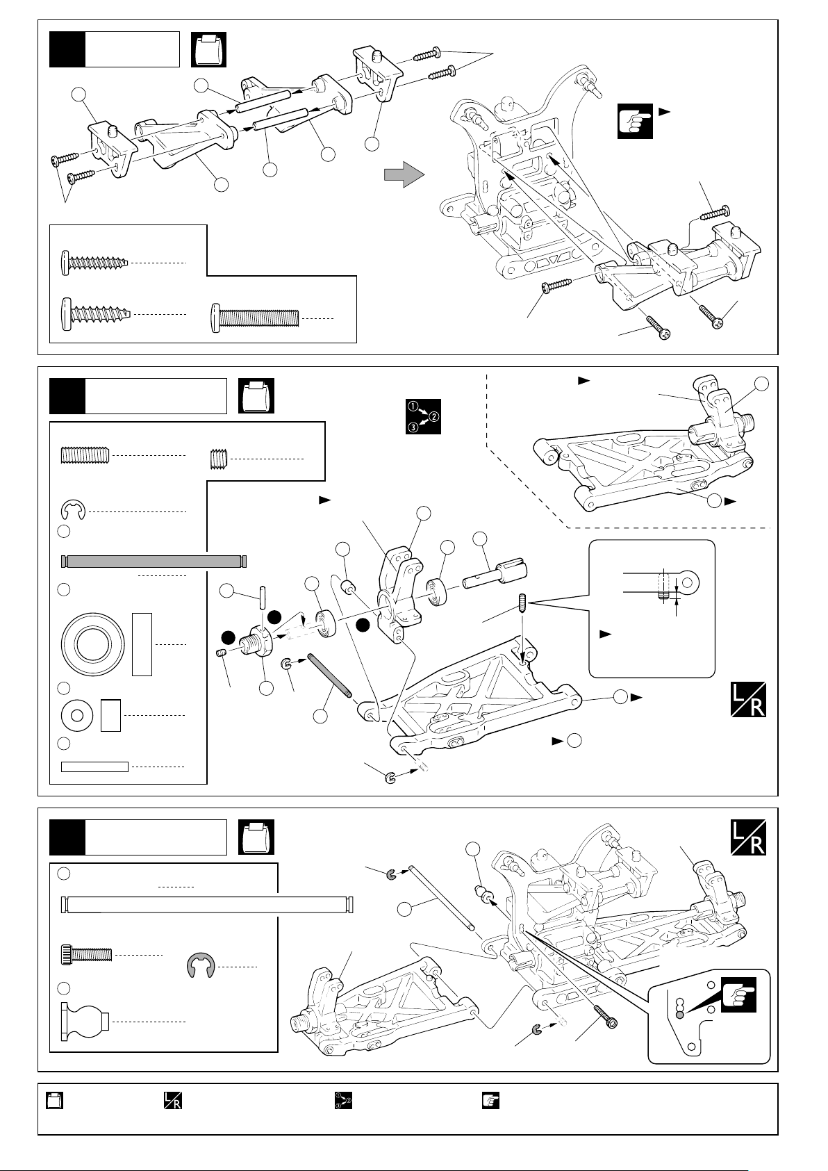
リヤサスペンション
Rear Suspension
7
4 x 12mm
Set Screw
E2.5 Eリング(銀)
E2.5 E-ring (Silver)
40
3 x 47mm
Shaft (Black)
7 8 x 16mm
Ball Bearing
セットビス
シャフト(黒)
ベアリング
31
28
4
4 x 20mm
Screw
2
5 x 4mm
Set Screw
2
< >
左側用
4
< >
For left side.
2
39
3
4
31
ビス
No.4, No.5
セットビス
2
30
2
2
Ò L Óのマーク
Ò L Ó marked.
36
7
ビスの種類に注意。
Note the types
29
4x15mm
< >
右側用
< >
For right side.
4x20mm
Ò R Óのマーク
Ò R Ó marked.
35
37
7
1
4x12mm
Top
上
Bottom
下
車高調整用
For adjusting the
ground clearance.
of screws !
4x15mm
32
1mm
4x20mm
34
右側用
Right
36
3 x 8 x 5mm
Plastic Collar
39
2.6 x 17mm
Shaft
プラカラー
シャフト
リヤサスペンション
Rear Suspension
8
41
4 x 74mm
Shaft
3 x 10mm
Cap Screw
42
7.8mm
Flange Ball (Black)
シャフト
キャップビス
座付ボール(黒)
5x4mm
2
2
2
E3 Eリング(黒)
E3 E-ring (Black)
2
2
38
E2.5
No.4, No.10
4
40
E2.5
左側用
For left side.
E3
41
42
E3
33
左側用
Left
を他のスペーサーと交換することで、
36
ホイールベースの変更ができます。
Wheel base adjustments can be made
by using other spacers.
右側用
For right side.
取付穴
3x10mm
Holes for
mounting.
使用する袋詰。
Part bags used.
10
左右同じように組立てる。
Assemble left and right
sides the same way.
番号の順に組立てる。
Assemble in the
specified order.
注意して組立てる所。
Pay close attention here!

リヤサスペンション
Rear Suspension
9
45
5 x 35mm
Set Screw
44
7.8mm
Ball End
セットビス
ボールエンド ボールエンド
No.5,
No.10
2
43
2
7.8mm
Ball End
2
約 14.5mm
approx. 14.5mm
リヤサスペンション
Rear Suspension
10
3mm
Nylon Nut
46
7.8mm
Ball
3 x 25mm
Cap Screw
ナイロンナット
ツバ付ボール
キャップビス
リヤサスペンション
Rear Suspension
11
45
44
43
x2
No.4, No.10
1
46
2
3
向きに注意。
2
2
Note the direction.
3mm
取付穴
Holes for mounting.
3x25mm
4
2
47
No.4,
No.10
3x10mm
48
50
49
48
3 x 3mm
Set Screw
3 x 4mm
Set Screw
3 x 10mm
Set Screw
3 x 12mm
Screw
2.6 x 5mm
F/H Screw
セットビス
セットビス
セットビス
ビス
サラビス
3x12mm
2
5.8mm
50
Ball
2
48
5.8mm
2
Ball End (S)
2
49
スタビボール(黒)
Stabilizer Ball (Black)
4
ボール
2
ボールエンド(S)
4
2
3x3mm
1
直径2.8mm
Diameter 2.8mm
52
3x4mm
2.6x5mm
3x3mm
51
52
3x4mm
2.6x5mm
2
使用する袋詰。
Part bags used.
左右同じように組立てる。
Assemble left and right
sides the same way.
原寸図。
True-to-scale diagram.
番号の順に組立てる。注意して組立てる所。
Assemble in the specified order.Pay close attention here!
可動するように組立てる。
Ensure smooth non-binding
movement while assembling.
2セット組立てる(例)。
x2
Assemble as many times as specified.
11
 Loading...