

Page 1
※ご使用前にこの説明書を良くお読みになり十分に理解してください。
Before beginning assembly, please read these instructions thoroughly.
R
THE FINEST RADIO CONTROL MODELS
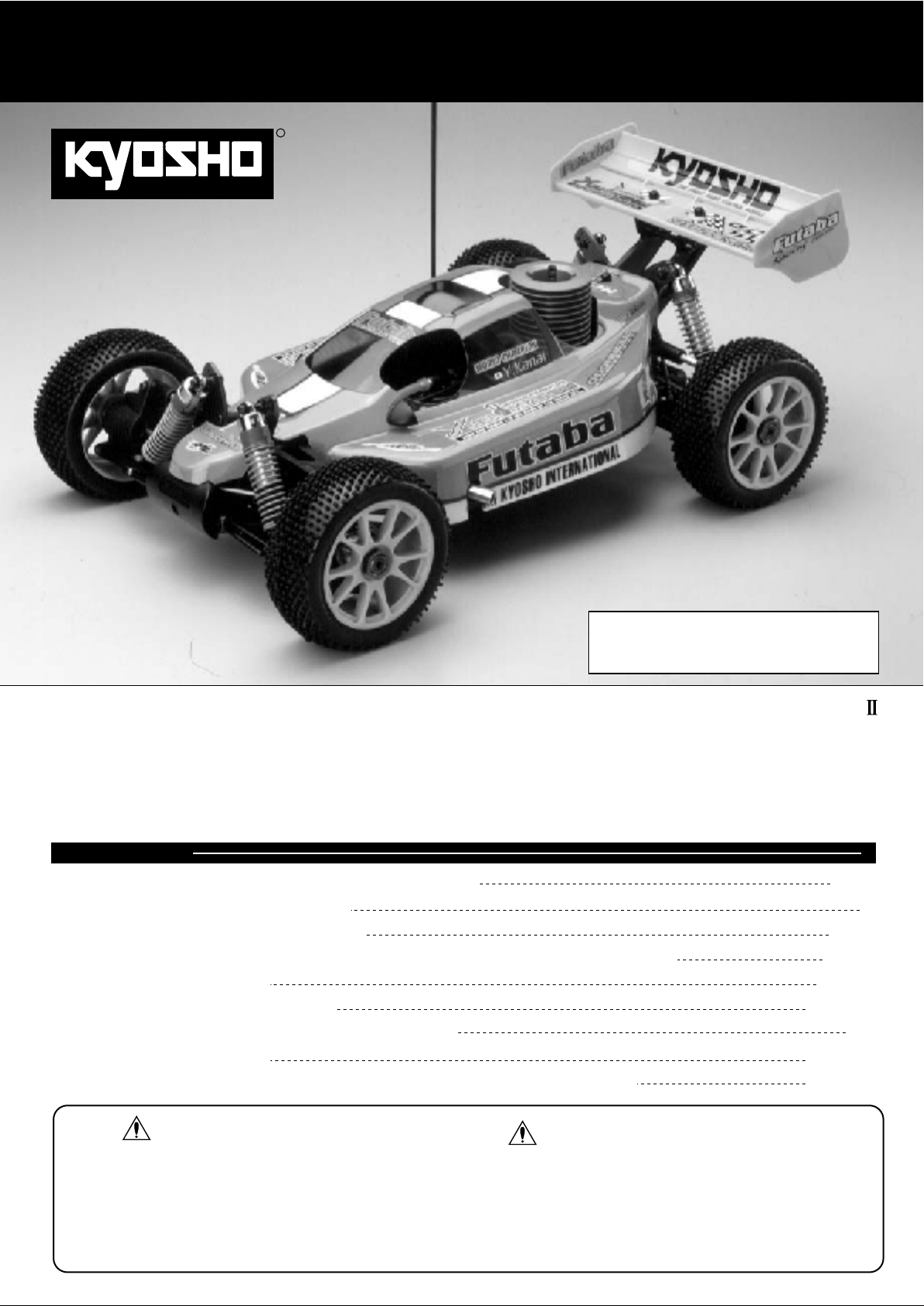
写真のボディ、ウイング用デカールはキットに付属しません。
組立/取扱説明書
INSTRUCTION MANUAL
1/8SCALERADIOCONTROLLED
通常のキットデカールが付属します。
Pictureshowsspecialdecalsnotincludedinthekit.
KitincludesstandardMP‑7.5decals.
インファーノMP‑7.5金井祐一エディション
.21ENGINEPOWERED4WDRACINGBUGGY
INFERNO MP-7.5
目 次 INDEX
●キットの他にそろえる物REQUIRED FOR OPERATION
●プロポの準備RADIO PREPARATION
●組立て前の注意BEFORE YOU BEGIN
●ランナー付プラパーツ配置図ARRANGEMENT OF PLASTIC PARTS ON RUNNERS
●本体の組立てASSEMBLY
●セッティングガイドADJUSTMENT
●取扱いの注意OPERATING YOUR MODEL SAFELY
●分解図EXPLODED VIEW
●スペアパーツ・オプションパーツリストSPARE PARTS & OPTIONAL PARTS
YUICHI KANAI EDITION 2
II
II
2 〜 3
3
4 〜 5
6 〜 7
8 〜 28
28 〜 29
30
31 〜 33
34 〜 37
安全のための注意事項
この無線操縦模型は玩具ではありません!
●この商品は高い性能を発揮するように設計されています。組立てに不慣れな方
は、模型を良く知っている人にアドバイスを受け確実に組立ててください。
●小さい部品があるので、組立て作業は幼児の手がとどかない所で必ずおこなっ
てください。
●動かして楽しむ場所は、万一の事故を考えて安全を確認してから、責任をもっ
てお楽しみください。
●組立てた後も、説明書がいつでも見られるように大切に保管してください。
※製品改良のため、予告なく仕様を変更する場合があります。 *SPECIFICATIONS ARE SUBJECT TO CHANGE WITHOUT NOTICE.※製品改良のため、予告なく仕様を変更する場合があります。 *SPECIFICATIONS ARE SUBJECT TO CHANGE WITHOUT NOTICE.
© 2002 KYOSHO CORPORATION/禁無断転載複製
●First-time builders should seek the advice of experienced modellers before
●Assemble this kit only in places out of children's reach!
●Take enough safety precautions prior to operating this model.
You are responsible for this model's assembly and safe operation!
●Always keep this instruction manual ready at hand for quick
reference, even after completing the assembly.
UNDER SAFETY PRECAUTIONS
This radio control model is not a toy!
beginning assembly and if they do not fully understand any part of the
construction.
No. 31271
Page 2
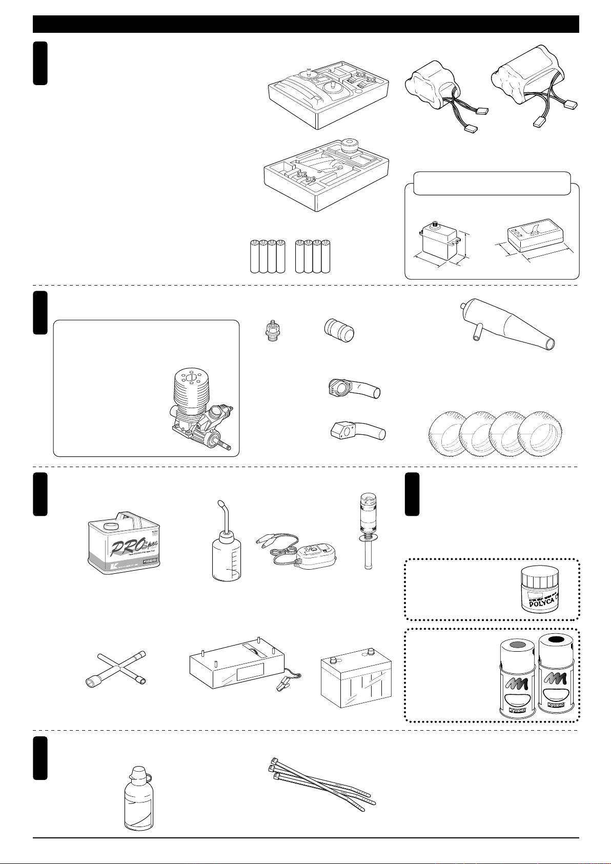
キットの他にそろえる物(1)REQUIRED FOR OPERATION (1)
2チャンネル2サーボ無線操縦機
1
(プロポ)
2ch radio control set with 2 servos.
●このキットには2チャンネル2サーボの
プロポが必要です。
●送信機にはスティックタイプとハンドル
タイプがありますが、お好みのタイプを
用意してください。
●スロットルサーボは、リバースで使用し
ます。
●プロポの取扱いは、プロポに付属の説明
書を参考にしてください。
●This kit requires a 2 channel radio con-
trol set with 2 servos.
●Because there are stick-type and wheeltype transmitters, use which ever fits
your convenience best.
●Switch the reverse (transmitter) for the
throttle control.
●For more information on the radio con-trol
set, refer to its instruction manual.
エンジンおよびマフラー
Engine / Muffler / Tire
2
●このキットには21クラスエンジンが必要です。
●This kit requires a .21 class engine.
■21クラスカー用エンジン
Engine for .21-class cars
パイロットシャフト、クラ
※
ンクシャフト一体型のエン
ジンに限ります。
Only using a type of .21
class engine, which is made
crank shaft and pilot shaft
as one part (SG shaft only).
■スティックタイプ
2チャンネルプロポ
Stick-type
2ch radio set.
■ハンドルタイプ
2チャンネルプロポ
Wheel-type
2ch radio set.
■単3乾電池(送信機用)
AA-size Batteries (For Transmitter)
AAAA
■プラグ
Plug
AAAA
■ジョイントパイプ
Joining Pipe
No.92515
マフラージョイントパイプ
Muffler Joining Pipe
■マニホールド
Manifold
No.39514
マニホールド(O.S.21RZ,ピコ,ノバロッシ)
Manifold (O.S.21RZ, Picco, Nova Rossi)
No.39516
マニホールド(O.S.21RG)
Manifold (
O.S.21RG)
■受信機用ニカドバッテリー
Battery for Receiver
No.71161
6V X-FORCE 600
ニカドバッテリー
Ni-Cd Battery
No.71641
6V-1000mAh
ニカドバッテリー
Ni-Cd Battery
使用できるサーボ・受信機サイズ
Suitable servos & receiver
■サーボ
Servo
38〜41mm
■マフラー
Muffler
■タイヤ
Tire
31〜36mm
18〜20mm
No.IFW-37
SP サイレンサー
SP Silencer (FEMCA)
■受信機
Receiver
29〜32mm
No.W-5651
スーパーマルチピンタイヤ
Super Multi Pin Tire
43〜48mm
(FEMCA)
燃料と始動用具
Required for engine starting:
3
■燃料
Glow Fuel
No.73802
RCモデルフュール
プロスペックフュール(バギー用)
RC Model Fuel
PRO Spec Fuel (Buggy)
■プラグレンチ
Plug Wrench
No.80312
ロッキングジグ/レンチ
Locking Jig & Wrench
その他
Other equipment required.
5
■ダンパーオイル
Shock Oil
■燃料ポンプ
Fuel Pump
No.96422
クイックフュールポンプ
Quick Fill Fuel Bottle
■スターター
Starter
No.1793
スターターボックス
Starter Box
■ストラップ(M)
Strap (M)
■プラグヒーター
Plug Heater
No.695142
DC急速充電器
DC Quick Charger
■スターター用バッテリー
Battery
No.695143
スパークブースター
Spark Booster
−
+
塗料
Paint
4
●ボディの塗装には塗料が必要です。
京商では、 モデル用塗料、スプレー
を販売していますのでご利用ください。
●For painting the body, use Kyosho
paints for models!
No.2230
ポリカカラー
POLYCA COLOR
No.76501〜76711
京商スプレーカラー
KYOSHO SPRAY COLOR
U
F
E
T
L
P
R
N
O
I
F
A
F
P
K
O
Y
H
S
O
S
P
R
O
R
L
A
O
Y
C
R
U
F
E
T
L
P
R
N
O
I
F
A
F
P
K
O
Y
H
S
O
S
P
R
O
R
L
A
O
Y
C
R
S
I
L
E
I
N
O
C
O
I
L
No.1701KP / KY
蛍光ストラップ
Fluorescent Strap
2
Page 3
キットの他にそろえる物(2)REQUIRED FOR OPERATION (2)
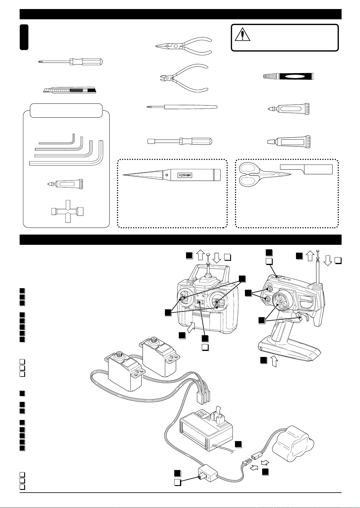
組立てに必要な工具
Tools required
6
■+ドライバー(大、中、小)
Phillips Screwdriver (L.M.S)
■カッターナイフ
Sharp Hobby Knife
キットに入っている工具
TOOLS INCLUDED
■六角レンチ(1.5mm,2mm,2.5mm,3mm)
Hex Wrench (1.5mm, 2mm, 2.5mm, 3mm)
■グリス
Grease
■十字レンチ
Cross Wrench
Grease
■ラジオペンチ
Needle Nose Pliers
■ニッパー
Wire Cutters
■キリ
Awl
■10mmボックスドライバー
Box Wrench
No.695101
ナイフエッジリーマー
KNIFE EDGE REAMER
下穴加工が不要で、直接
1mm〜15mmの正確な穴
あけができる工具です。
No need to pre-drill!
Drills neat 1mm to 15mm
holes directly!
使用する工具の取扱いには、
十分注意してください。
CAUTION: Handle tools carefully!
注意
■瞬間接着剤
Instant Glue
■ネジロック剤
Screw Cement
ネジロック剤
■ゴム系接着剤
Rubber Cement
ゴム系接着剤
No.1829
ラウンドカッター&サンダー
ROUND CUTTER & SANDER
ボディのカット、仕上
げ用。曲線部分も楽に
作業ができます。
For trimming bodies!
Cutting along curved lines
never was so easy!
プロポの準備 RADIO PREPARATION
●プロポを下の順番にしたがってセットします。
Set up the radio control system as indicated below.
●始める時
1
送信機に単3乾電池をセットす
る。
2
送信機のアンテナをのばす。
3
電充電した受信機用ニカド
バッテリーをつなぐ。
4
受信機のアンテナをのばす。
5
トリムを中央にセットする。
6
送信機のスイッチを入れる。
7
受信機のスイッチを入れる。
8
ハンドル/トリガー を動かして
●終わる時
9
受信機のスイッチを切る。
10
送信機のスイッチを切る。
11
送信機のアンテナを縮める。
●START
1
Insert AA-size batteries into the
Transmitter.
2
Extend the Transmitter antenna.
3
Connect the charged Ni-Cd battery to the receiver.
4
Unwind the Receiver antenna.
Center the Transmitter trims.
5
Switch "ON" the Transmitter.
6
Switch "ON" the Receiver.
7
Make sure the servos move ac-
8
cording to your transmitter inputs.
●FINISH
9
Switch "OFF" the Receiver.
10
Switch "OFF" the Transmitter.
11
Retract the Transmitter antenna.
サーボ▼
Servo
Transmitter
送信機
▲
5
ON
OFF
ON
2
11
10
6
OFF
2
11
8
5
8
1
10
ON
6
OFF
1
▼受信機
Receiver
4
▼スイッチ
Switch
7
3
▲バッテリー
Battery
9
3
Page 4
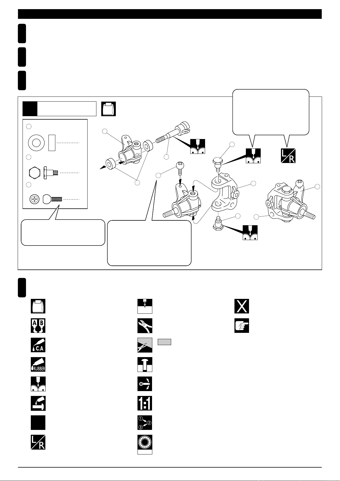
組立て前の注意(1) BEFORE YOU BEGIN (1)
組立てる前に説明書を良く読んで、おおよその構造を理解してから組立てに入ってください。
1
Read through the manual before you begin, so you will have an overall idea of what to do.
キットの内容をお確かめください。万一不良、不足がありましたら、お買い求めの販売店にご相談いただくか、当社「ユーザー相談室」までご連絡ください。
2
Check all parts. If you find any defective or missing parts, contact your local dealer or our Kyosho Distributor.
説明書の見かた
3
How to read the instruction manual:
〔説明例Example〕
説明書内では多くのマークが使用
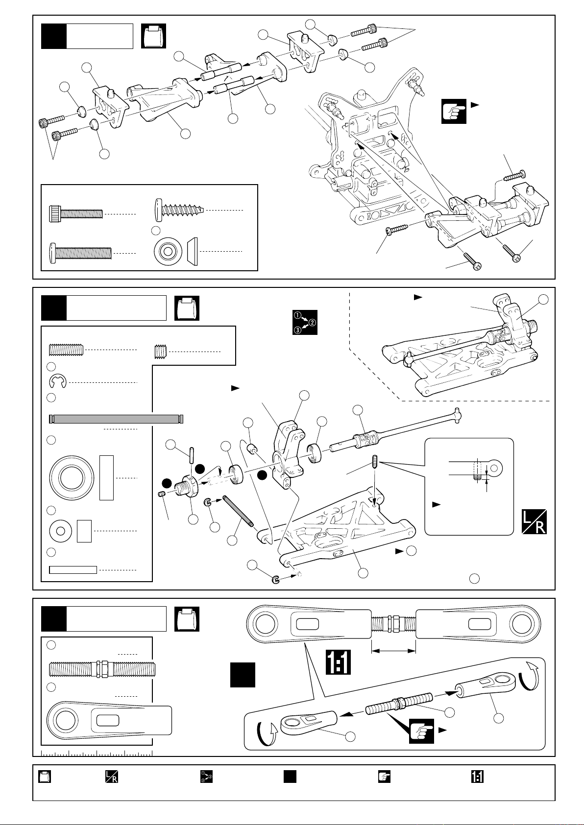
フロントサスペンション
Front Suspension
1
4
5 x 10mm メタル
Metal Bushing
No.4, No.5, No.6
1
されています。マークに注意して
組立てを進めてください。
This instruction manual uses several symbols. Please note them
during the entire assembly.
4
キングピン
5
King Pin
4
5.8mm ピロボール(黒)
6
Pillow Ball (Black)
2
小物部品の名前、原寸図、使用数。
Key Number, Part Name, True-to-scale
Diagram, Quantity Used
説明書に使われているマーク
4
Symbols used throughout the instruction manual, comprise:
使用する袋詰。
Part bags used.
キット内の部品は、ビス類を除いてキー
No.が付けられています。スペアパーツを
購入する時はキーNo.を参照して下さい。
All parts except screws are identified by
key numbers. For purchasing spare parts,
find the key no. of the part needed in the
spare part list and refer to the left column
to look up the corresponding order no.
4
2mm
3
6
2mmの穴をあける(例)。
Drill holes with the specified
diameter (here: 2mm).
5
7
R
L
5
8
別購入品
Must be purchased separately!
2
x2
エポキシ接着剤で接着する。
Apply epoxy glue.
瞬間接着剤で接着する。
Apply instant glue (CA glue, super glue).
ゴム系接着剤で接着する。
Apply rubber cement.
グリスを塗る。
Apply grease.
ネジロック剤を塗る。
Apply threadlocker (screw cement).
2セット組立てる(例)。
Assemble as many times as
specified (here: twice).
左右同じように組立てる。
Assemble left and right sides
the same way.
1901
余分をカットする。
Cut off excess.
をカットする。
Cut off shaded portion.
仮止め。
Tentatively tighten.
可動するように組立てる。
Ensure smooth non-binding
movement while assembling.
原寸図
True-to-scale diagram.
番号の順に組立てる。
Assemble in the specified
order.
オプションのベアリングの品番。
例:No.1901
Ball bearings are optional!
(with optional part no.)
注意して組立てる所。
Pay close attention here!
4
Page 5
組立て前の注意(2) BEFORE YOU BEGIN (2)
キットには、形や長さが違うビスや小物部品が多く入っています。説明書には原寸図がありますので確認してから組立ててください。
5
また、ビス類は多めに入っているものもありますので、予備としてお使いください。
This kit contains screws and hardware in different metric sizes and shapes.
Before using them, check the screws on the true-to-scale diagrams on the left side in each assembly step. Some screws are extras.
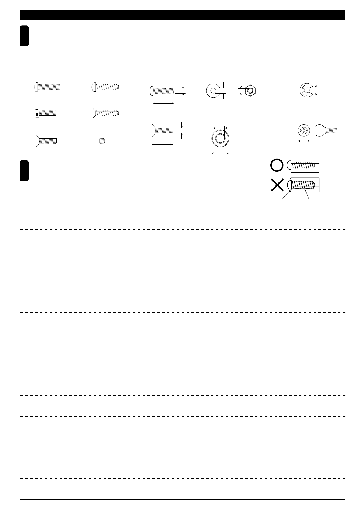
●ビスの種類 SCREWS
ビス Screw
キャップビス
Cap Screw
サラビス
Flat Head (F/H) Screw
TPビスは、部品にネジを切りながらしめつけるビスです。しめこみが固い場合がありますが、
6
部品が確実に固定されるまでしめこんでください。ただし、しめすぎるとネジがきかなくなり
ますので、部品が変形するまでしめないでください。
Self-tapping (TP) screws cut threads into the parts when being tightened. Excessive force may
permanently damage parts when tightening TP screws. It is recommended to stop tightening when
the part is attached or when some resistance is felt after the threaded portion enters the plastic.
TPビス
Self-tapping (TP) Screw
TPサラビス
TP F/H Screw
セットビス
Set Screw
●小物部品のサイズ例 OTHER HARDWARE
3x12mmビス
Screw
12mm
3x12mmサラビス
F/H Screw
3mm
12mm
3mmワッシャー・ナット
Washer・Nut
3mm
5x10mmメタル・ベアリング
Metal Bushing・Bearing
5mm
10mm
MEMO
3mm
Correct
Wrong
しめすぎ
Overtightened.
E3Eリング
E-ring
3mm
6.8mmピロボール
Pillow Ball
6.8mm
ビスがきかない
The threads are stripped.
5
Page 6
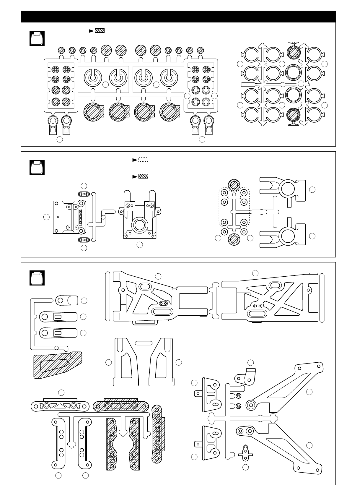
ランナー付プラパーツ配置図(1)
部の部品は使用しません。
No.1
Shaded parts are not used.
ARRANGEMENT OF PLASTIC PARTS ON RUNNERS (1)
No.4
17
284
49
283
166
283
288288
166
284
部の部品は、セッティング用に使用してくだい。
Use the parts within the dotted lines as tunning options.
部の部品は使用しません。
Shaded parts are not used.
166 166
163
166 166
35
No.5
21
41
41
49
72
16
70
261 261
29
36
36
24
34
37
28
30
29
25
189
62
6
Page 7

ランナー付プラパーツ配置図(2)
No.6
ARRANGEMENT OF PLASTIC PARTS ON RUNNERS (2)
17
No.9
49
49
146
142
259 258
16
144 145
147
143
部の部品は使用しません。
Shaded parts are not used.
91
141
123
122
126
134
133
128
101
133
127
149
125 129
149
7
Page 8
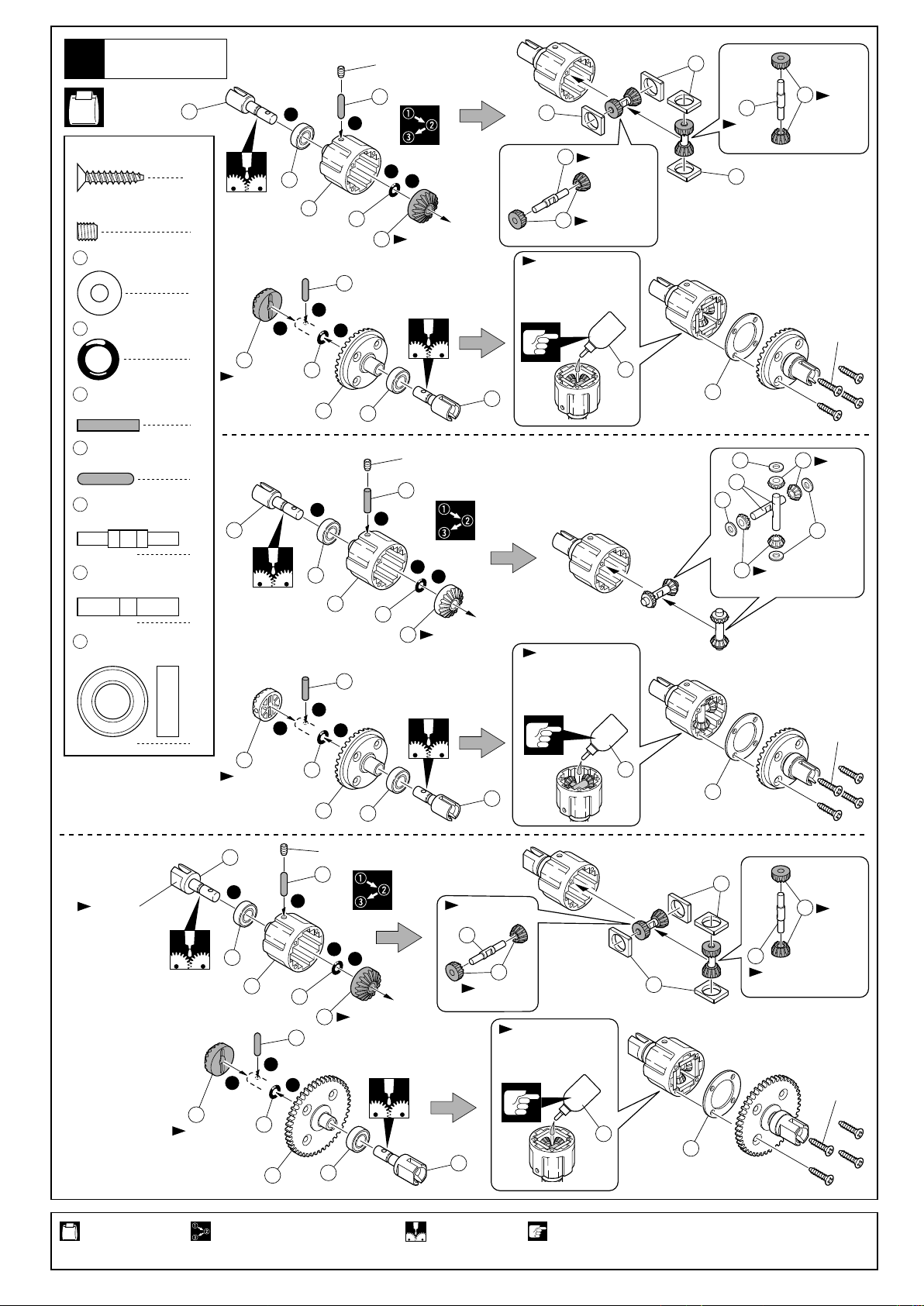
デフギヤ
Gear Differential
1
No.2
3 x 15mm
TP F/H Screw
4 x 4mm
Set Screw
11
4 x 10mm
Shim
6 6mm
O-ring
4
2.6 x 14mm
Shaft (Black)
201
2.6 x 12.8mm
Shaft (Black)
デフシャフト(A)
202
Differential Shaft (A)
デフシャフト(B)
9
Differential Shaft (B)
5 8 x 16mm
Ball Bearing
TPサラビス
セットビス
Oリング
8
12
シム
シャフト(黒)
シャフト(黒)
ベアリング
3
4
6
2
< >
< >
4
8
4
2
6
< >
フロント用
< >
For Front
1
5
1
2
3
204
18 T(黒)
18 T (Black)
6
リヤ用
For Rear
1
5
2
3
2
20 T(銀)
20 T (Silver)
6
12
12
203
202
段付有り
Step
203
205
12 T
(黒)
12 T
(Black)
3x15mm
201
1
3
6
4x4mm
201
2
204
4
18 T(黒)
18 T (Black)
203
202
段付有り
Step
205
12 T(黒)
12 T (Black)
LSDギヤオイル
TCD Gear Oil
※オイルは8分目まで入れる。
Fill up to 80%.
251
8
15
5
4x4mm
4
3
2
4
1
6
20 T(銀)
2
20 T (Silver)
4
1
シリコンオイル#1000
Silicone Oil #1000
※オイルは8分目まで入れる。
Fill up to 80%.
11
9
11
10
10
10 T(銀)
10 T (Silver)
10 T
(銀)
10 T
(Silver)
11
3x15mm
293
8
15
5
< >
センター用
< >
For Center
平らな面
Flat surface
使用する袋詰。
Part bags used.
8
7
4x4mm
201
1
3
5
1
6
204
201
2
3
204
18 T(黒)
18 T (Black)
1
6
13
番号の順に組立てる。
Assemble in the specified order.
2
5
4
18 T(黒)
18 T (Black)
段付有り
Step
202
205
12 T(黒)
12 T (Black)
※オイルは8分目まで入れる。
7
グリスを塗る。
Apply grease.
LSDギヤオイル
TCD Gear Oil
Fill up to 80%.
注意して組立てる所。
Pay close attention here!
251
203
15
203
202
段付有り
Step
205
3x15mm
12 T
(黒)
12 T
(Black)
Page 9
リヤギヤボックス
Rear Gearbox
2
No.2, No.4,
No.5, No.10
4 x 20mm
TP Screw
4 x 25mm
TP F/H Screw
192013 x 16mm
5 8 x 16mm
TPビス
TPサラビス
シム(厚 Thick)
シム(薄 Thin)
Shim
ベアリング
Ball Bearing
リヤギヤボックス
Rear Gearbox
3
5 x 4mm
Set Screw
4 x 10mm
Screw
セットビス
ビス
1
2
5
4x20mm
5
2
16
18
3
2
21
2
19,20
2
No.4, No.5,
19 20
枚数を変えて、バック
ラッシュを調整する。
Adjust the backlash
with the shims.
平らな面にセットビスを固定する。
Tighten the set screw to the flat spot.
17
4x10mm
4x25mm
No.10
5x4mm
1
2
24
4 x 15mm
TP Screw
TPビス
リヤダンパーステー
Rear Shock Stay
4
3 x 20mm
Cap Screw
3 x 10mm
TP Screw
3 x 12mm
TP Screw
4 x 10mm
Screw
キャップビス
TPビス
TPビス
ビス
長
208
Long
2
252
4x15mm
No.4, No.5, No.10
2
1
3x20mm
2
2
25
取付穴
Holes for
mounting.
253
使用する袋詰。 ネジロック剤を塗る。 注意して組立てる所。
Part bags used. Apply threadlocker
(screw cement).
Pay close attention
here!
3x10mm
27
左右同じように組立てる。
Assemble left and right
sides the same way.
番号の順に組立てる。
Assemble in the
specified order.
4x10mm
3x12mm
グリスを塗る。
Apply grease.
9
Page 10
ウィングステー
Wing Stay
5
210
29
No.4, No.5, No.10
209
29
210
3x15mm
210
3x15mm
3 x 15mm
Cap Screw
4 x 20mm
Screw
キャップビス
ビス
リヤサスペンション
Rear Suspension
6
4 x 12mm
Set Screw
39
Eリング(銀)
38
3 x 48mm
Shaft (Black)
5 8 x 16mm
Ball Bearing
セットビス
シャフト(黒)
ベアリング
210
E-ring (Silver)
28
4 x 15mm
TP Screw
4
210
3mm
Head Washer
2
5 x 4mm
Set Screw
2
4
< >
< >
2
TPビス
ヘッドワッシャー
セットビス
左側用
For left side.
54
209
2
4
No.4, No.10
2
Ò L Óのマーク
Ò L Ó marked.
36
5
30
34
ビスの種類に注意。
Note the types
of screws !
4x15mm
4x20mm
4x15mm
4x20mm
< >
右側用
< >
For right side.
Ò R Óのマーク
Ò R Ó marked.
35
68
5
Top
上
3 x 8 x 5mm
36
Plastic Collar
54
2.6 x 17mm
Shaft
プラカラー
シャフト
リヤサスペンション
Rear Suspension
7
254
リヤアッパーロッド
Rear Upper Rod
41
7.8mm
ボールエンド
Ball End
4
2
3
5x4mm
2
33
39
1
4x12mm
Bottom
下
車高調整用
For adjusting the
ground clearance.
1mm
38
を他のスペーサーと交換することで、
36
2
39
37
ホイールベースの変更ができます。
Adjust the wheel base by using the other
spacer instead of .
36
No.4
2
約 16mm
approx. 16mm
x2
4
41
254
逆ネジ
Reverse screw
41
使用する袋詰。
Part bags used.
10
左右同じように組立てる。
Assemble left and right
sides the same way.
Assemble in the
specified order.
2セット組立てる(例)。番号の順に組立てる。
x2
Assemble as many times
as specified.
注意して組立てる所。
Pay close attention here!
原寸図。
True-to-scale diagram.
Page 11
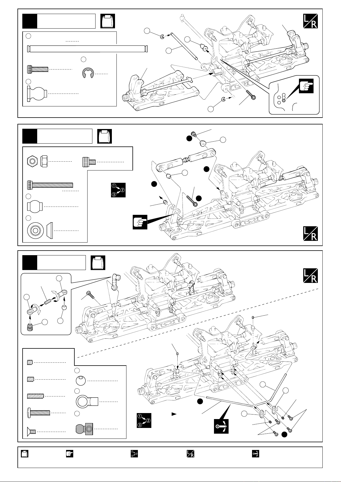
リヤサスペンション
Rear Suspension
8
43
4 x 74mm
Shaft
3 x 10mm
Cap Screw
45
7.8mm
Flange Ball (Black)
シャフト
キャップビス
座付ボール(黒)
2
44
2
2
Eリング(黒)
E-ring (Black)
4
No.4, No.10
左側用
For left side.
44
43
45
44
3x10mm
右側用
For right side.
取付穴
Holes for
mounting.
リヤサスペンション
Rear Suspension
9
3mm
ナイロンナット
Nylon Nut
3 x 25mm
Cap Screw
48
7.8mm
Ball
210
3mm
Head Washer
キャップビス
ツバ付ボール
ヘッドワッシャー
リヤサスペンション
Rear Suspension
10
51
3x10mm
3 x 4mm
Cap Screw
2
2
2
2
キャップビス
Holes for mounting.
No.4, No.10
2
取付穴
No.4,
No.10
3mm
3x4mm
4
48
2
3x25mm
210
1
3
51
255
52
3 x 3mm
Set Screw
3 x 4mm
Set Screw
3 x 10mm
Set Screw
3 x 12mm
Screw
2.6 x 5mm
F/H Screw
使用する袋詰。
Part bags used.
セットビス
セットビス
セットビス
ビス
サラビス
3x12mm
3x3mm
3x3mm
2
5.8mm
255
2
51
2
2
52
4
注意して組立てる所。 可動するように組立てる。
Pay close attention here! Ensure smooth non-binding
ボール
Ball
5.8mm
ボールエンド(S)
Ball End (S)
スタビボール(黒)
Stabilizer Ball (Black)
2
4
2
直径2.8mm
Diameter 2.8mm
番号の順に組立てる。
Assemble in the
specified order.
1
49
3x4mm
2.6x5mm
左右同じように組立てる。
Assemble left and right
sides the same way.
50
49
3x4mm
2
movement while assembling.
2.6x5mm
11
Page 12
11
シャシー
Chassis
No.9, No.10
4 x 20mm
TP F/H Screw
12
3 x 10mm
F/H Screw
3 x 18mm
Cap Screw
TPサラビス
シャシー
Chassis
サラビス
キャップビス
1
1
4
No.4,
No.9,
No.10
58
長い
Long
76
55
4x20mm
57
4x20mm
3x18mm
56
56
トルクロッドボール
Torque Rod Ball
58
6.8mm
ボールエンド(L)
Ball End (L)
フロントギヤボックス
Front Gearbox
13
4 x 20mm
TP Screw
5 8 x 16mm
Ball Bearing
TPビス
ベアリング
1
2
4
2
76
6.8mm
Ball
5
ツバ付ボール
1
1
3x10mm
No.6, No.10
16
4x20mm
5
256
3
18
2
192013 x 16mm
Shim
使用する袋詰。
Part bags used.
12
シム(厚 Thick)
シム(薄 Thin)
番号の順に組立てる。
Assemble in the specified order.
2
19 20
枚数を変えて、バックラッシュを調整する。
Adjust the backlash with the shims.
グリスを塗る。
Apply grease.
19,20
4x20mm
17
Page 13

フロントギヤボックス
Front Gearbox
14
5 x 4mm
Set Screw
4 x 15mm
TP F/H Screw
セットビス
TPサラビス
No.5, No.6, No.10
平らな面にセットビスを
固定する。
1
2
Tighten the set screw to
the flat spot.
5x4mm
62
4 x 20mm
TP F/H Screw
TPサラビス
フロントダンパーステー
Front Shock Stay
15
Holes for mounting.
3 x 20mm
Cap Screw
4 x 10mm
Screw
キャップビス
ビス
2
取付穴
2
4
257
No.6, No.10
3x20mm
27
短
213
Short
4x20mm
4x15mm
4x10mm
3 x 12mm
TP Screw
TPビス
フロントサスペンション
Front Suspension
16
4 x 10mm
Cap Screw
5548 x 16mm
Ball Bearing
2.6 x 17mm
Shaft
5 x 4mm
Set Screw
69
ナックルカラー
Knuckle Collar
キャップビス
ベアリング
シャフト
セットビス
214
2
3x12mm
4x10mm
4x10mm
3x12mm
No.6, No.10
258
< >
右側用
4
< >
For right side.
ÒRÓのマーク
ÒRÓ marked.
4
66
69
ÒRÓのマーク
ÒRÓ marked.
5
54
2
2
5
1
3
2
69
4x10mm
294
ÒLÓのマーク
ÒLÓ marked.
67
< >
左側用
< >
For left side.
259
33
5x4mm
4
ÒLÓのマーク
ÒLÓ marked.
使用する袋詰。
Part bags used.
番号の順に組立てる。
Assemble in the
specified order.
左右同じように組立てる。
Assemble left and right
sides the same way.
ネジロック剤を塗る。
Apply threadlocker
(screw cement).
注意して組立てる所。
Pay close attention here!
13
Page 14

フロントサスペンション
Front Suspension
17
右側用
For right side.
No.5, No.6, No.10
左側用
For left side.
39
1
71
4 x 12mm
Set Screw
39
Eリング(銀)
E-ring (Silver)
44
Eリング(黒)
E-ring (Black)
セットビス
39
2
71
3 x 38mm
Shaft
4
43
4 x 74mm
Shaft
4
1
43
44
4x12mm
2
2
3
44
3
シャフト
2
シャフト
2
70
Top
上
Bottom
下
車高調整用
For adjusting the ground clearance.
1mm
フロントサスペンション
Front Suspension
18
76
6.8mm
ツバ付ボール
Ball
260
フロントアッパーロッド
Front Upper Rod
39
Eリング(銀)
75
3 x 40mm
Shaft (Black)
3 x 22mm
Cap Screw
3mm
Nylon Nut
72
6.8mm
Ball End
E-ring (Silver)
シャフト(黒)
キャップビス
ナイロンナット
ボールエンド
No.5, No.6, No.10
2
逆ネジ
Reverse screw
260
261
2
1
2
4
長
Long
4
39
75
39
72
2
2
2
2
76
約8.5mm
approx. 8.5mm
3mm
3x22mm
3
使用する袋詰。
Part bags used.
14
左右同じように組立てる。
Assemble left and right
sides the same way.
番号の順に組立てる。
Assemble in the specified order.
注意して組立てる所。
Pay close attention here!
原寸図。
True-to-scale
diagram.
Page 15

フロントサスペンション
Front Suspension
19
No.6
No.10
3x10mm
51
216
3 x 3mm
Set Screw
3 x 4mm
Set Screw
3 x 10mm
Set Screw
3 x 12mm
Screw
2.6 x 5mm
F/H Screw
255
51
216
セットビス
セットビス
セットビス
ビス
サラビス
5.8mm
ボール
Ball
5.8mm
ボールエンド(S)
Ball End (S)
スタビボール(銀)
Stabilizer Ball (Silver)
51
3x12mm
255
2
2
2
2
4
3x3mm
3x3mm
262
2
1
4
2
直径2.5mm
Diameter 2.5mm
49
3x4mm
2.6x5mm
49
3x4mm
2.6x5mm
2
シャシー
Chassis
20
3 x 10mm
TP Screw
4 x 20mm
TP F/H Screw
TPビス
TPサラビス
No.6, No.10
1
4
1
77
3x10mm
2
2
4x20mm
4x20mm
使用する袋詰。
Part bags used.
左右同じように組立てる。
Assemble left and right
sides the same way.
番号の順に組立てる。
Assemble in the
specified order.
可動するように組立てる。
Ensure smooth non-binding
movement while assembling.
15
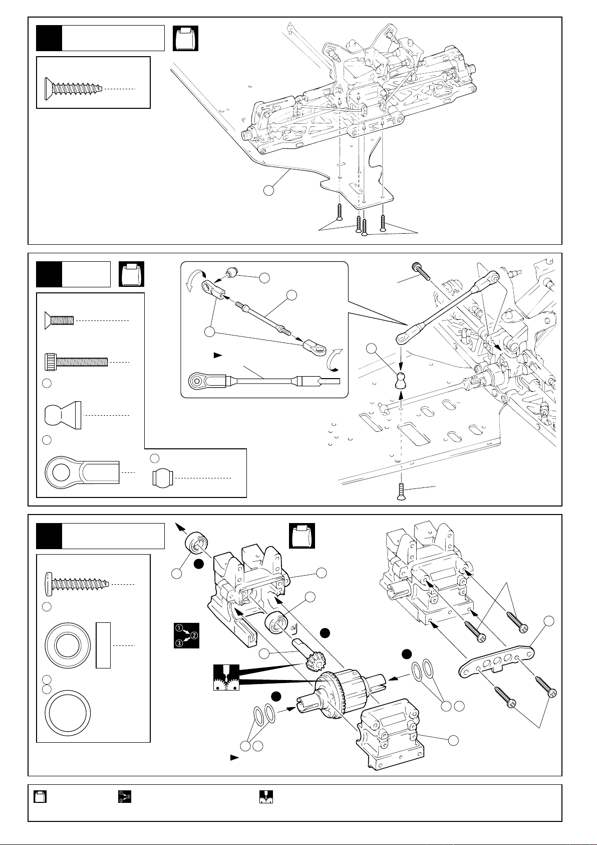
Page 16

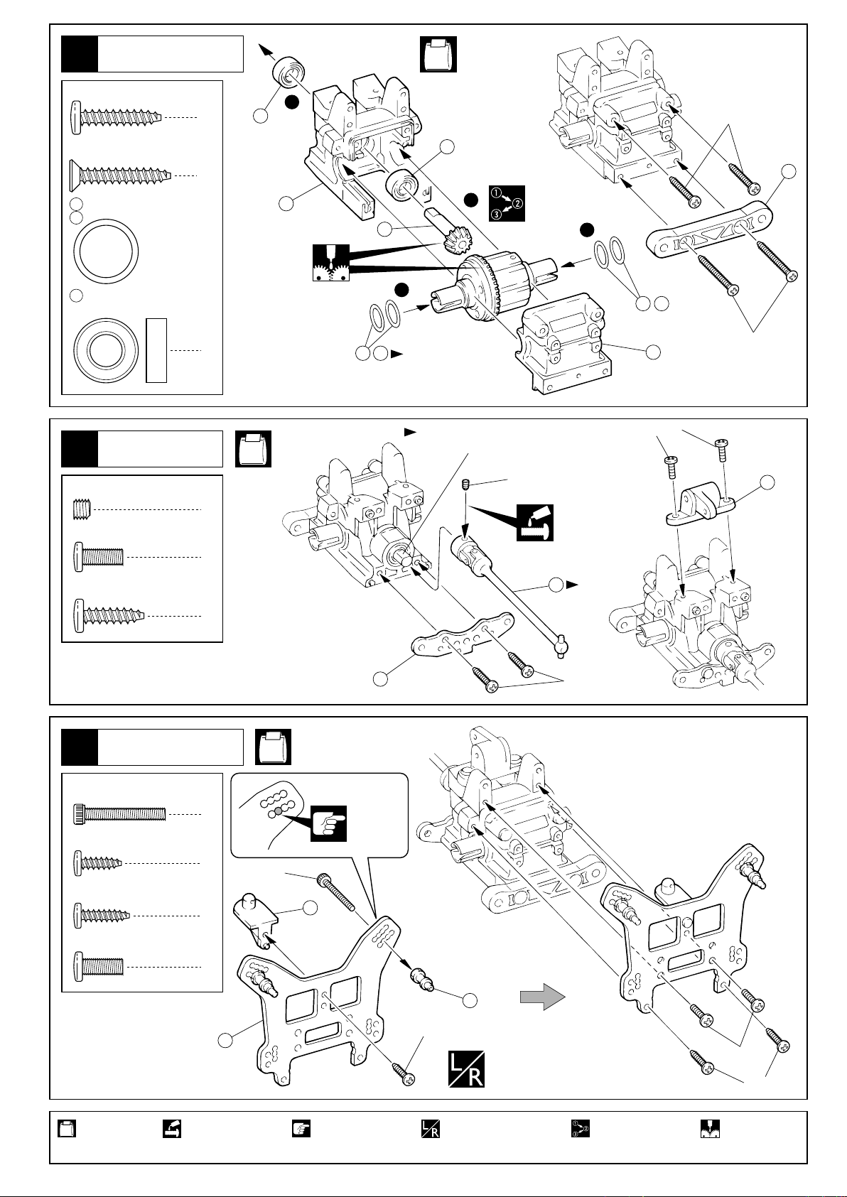
センターギヤボックス
Center Gearbox
21
218
263
No.8
78
ブレーキキャリパー
Brake Caliper
79
ブレーキパッド(黒)
Brake Pad (Black)
センターギヤボックス
Center Gearbox
22
78
6
218
20mm
Disk Plate Bolt
8
79
78
79
ディスクプレートボルト
4
No.9, No.10
149
263
78
82
センターデフ
Center Differential
83
149
78
79
78
79
263
約13mm
approx. 13mm
263
78
218
4 x 15mm
TP F/H Screw
3 x 8mm
TP F/H Screw
23
TPサラビス
TPサラビス
センターギヤボックス
Center Gearbox
No.8, No.9, No.10
3 x 3mm
Set Screw
3 x 10mm
TP F/H Screw
220
セットビス
TPサラビス
3mm
サラワッシャー
F/H Washer
4
3x8mm
4
89
90
3x3mm
2
88
91
3x8mm
220
4x15mm
4x15mm
3x3mm
3x10mm
220
91
87
91
7mm14mm
ロッドがプレ
ートにあたる
場合はペンチ
で曲げる。
Bend the rods
if they contact
the plate.
厚いものを使用。
Use thick one.
89
2
88
87
2
使用する袋詰。 注意して組立てる所。 ゴム系接着剤で接着する。
Part bags used. Pay close attention here!
Apply rubber type glue.
16
Page 17

ステアリング
Steering
24
4 x 10mm
F/H Screw
3mm
Flanged Nut
99
ステアリングピン
Steering Pin
サラビス
フランジ付ナット
98
ステアリングカラー
Steering Collar
2
221
6 x 10mm
Ball Bearing
2
3 x 10mm
Washer
2
No.7, No.10
ベアリング
ワッシャー
2
4
2
短い
Short
4x10mm
222
221
221
長い
Long
98
99
4x10mm
265
3x10mm
3mm
95
221
223
221
98
99
向きに注意。
Note the direction.
3x10mm
3mm
ステアリング
Steering
25
3 x 10mm
F/H Screw
3 x 15mm
F/H Screw
3 x 18mm
F/H Screw
4 x 10mm
Screw
4 x 10mm
F/H Screw
3 x 8mm
Cap Screw
266
210
サラビス
サラビス
サラビス
ビス
サラビス
キャップビス
6.8mm
ボール
Ball
3mm
ヘッドワッシャー
Head Washer
3mm
Nut
1
291
テーパーカラー
Tapered Collar
2
292
3x6x2mm
Collar
2
3mm
Flanged Nut
1
56
トルクロッドボール
4
Torque Rod Ball
1
224
タイロッド
Tie Rod
4
1
No.7, No.10
ナット
2
2
カラー
2
フランジ付ナット
2
2
58
短い
Short
225
4mm
サラワッシャー
F/H Washer
58
6.8mm
ボールエンド(L)
Ball End (L)
3mm
4
6
2
(フランジ付)
(Flanged)
4x10mm
226
ビスの種類に注意。
Note the types
of screws !
3x8mm
101
4x10mm
225
225
210
225
56
4x10mm
仮止めのビスを外して使う。
Remove these screws
and retighten after
長い
installing .
Long
短い
Short
100
4x10mm
266
100
向きに注意。
Note the
direction.
56
3x10mm
292
291
3x15mm
約24mm
approx. 24mm
取付穴
Holes for
mounting.
使用する袋詰。 ネジロック剤を塗る。 注意して組立てる所。
Part bags used. Apply threadlocker
左右同じように組立てる。
Assemble left and right
sides the same way.
3mm
(screw cement).
3x18mm
原寸図。 仮止め。
True-to-scale
diagram.
Pay close attention here!
58
224
逆ネジ
Reverse screw
Tentatively tighten.
17
Page 18

エンジン
Engine
26
クランクシャフトを引っ張り
出した状態で組み立てます。
Assemble the following parts
with pulling the crankshaft.
必ずキット付属の テーパー
コレットを使用する。
Use taper collet
105
included in the kit.
105
No.3
エンジン
Engine
エンジン
Engine
267
107
105
テーパーコレット
Tapered Coret
107
パイロットナット
Pilot Nut
268
3 x 5 x 0.2mm
Shim
シム
105
270
268
269
1
269
269
268
の短い方を の溝に入れる。
The short side of must
be in the groove of .
107270
270
107
270
1
270
107
3
270
エンジン
Engine
27
3 x 6mm
Cap Screw
3 x 10mm
Cap Screw
5 x 8 x 0.2mm
Shim
※
キャップビス
キャップビス
シム
エンジンによってワッシャー及び
シムの種類、枚数を調整する。
A number and / or type of shim need to be
adjusted depending on the type of engine.
5 x 10mm
Washer
1
111
5 x 10mm
Ball Bearing
4
210
3mm
Head Washer
2
3x6mm
ヘッドワッシャー
No.3
ワッシャー
ベアリング
110
5 x 20mm
Shim
1
2
1
5x10mm
210
シム
111
1
5x8x0.2mm
エンジン
Engine
3x10mm
110
111
5x8x0.2mm
112
227
使用する袋詰。 注意して組立てる所。 別購入品。 可動するように組立てる。
Part bags used. Pay close attention here! Must be purchased separately!
Ensure smooth non-binding
movement while assembling.
18
Page 19

28
エンジン
Engine
180
No.3, No.10
紙1枚分のすきまをあける。
Insert a sheet of paper
before installing.
前
Front
180
4 x 6mm
F/H Screw
4 x 10mm
Flanged Cap Screw
サラビス
フランジ付キャップビス
マフラー
Muffler
29
4 x 4mm
Set Screw
3 x 6mm
F/H Screw
セットビス
サラビス
4
4
1
2
4x10mm
4x10mm
4x6mm
4x6mm
No.9, No.10
マニホールド
Manifold
4x4mm
185
184
マフラーに合わせて曲げる。
3x6mm
使用する袋詰。 別購入品。
Part bags used. Must be purchased separately!
Bend so it fits into the muffler.
マフラー
Muffler
マフラージョイント
パイプ
Muffler Joining Pipe
ナイロン
ストラップ
Nylon Strap
19
Page 20

30
燃料タンク
Fuel Tank
No.8, No.9,
No.10
3x15mm
3x15mm
121
183
122
3 x 15mm
TP Screw
3 x 10mm
TP F/H Screw
TPビス
2
TPサラビス
2
183
3x10mm
ビスの種類に注意。
Note the types of screws !
123
Oリングの向きに注意。
Note the direction for O-ring.
228
271
エンジン、マフラーに合せてシリコン
チューブの長さを調節する。
Cut the Silicone Tube, depending
271
on Engine and Muffler.
プロポ
Radio
31
No.9, No.10
3 x 6mm
Screw (Silver)
3 x 8mm
Screw
2 x 20mm
Screw
2 x 30mm
Screw
2 x 8mm
TP Screw
ビス(銀)
ビス
ビス
ビス
TPビス
127
1
127
2
125
2x20mm
126
2x30mm
2x8mm
2x8mm
272
3x6mm
2x8mm
128
1
スイッチ
1
7
Switch
使用する袋詰。
Part bags used.
20
3x8mm
スイッチ
Switch
注意して組立てる所。 別購入品。
Pay close attention here! Must be purchased
125
193
separately!
2mm
2mm
specified diameter.
129
をカットする。2mmの穴をあける(例)。
Cut off shaded portion.Drill holes with the
Page 21

32
プロポ
Radio
275
274
273
アンテナ
Antenna
131
No.10
受信機
Receiver
メカボックスのすき間には、
スポンジ等を入れると良い。
Better to fill some sponge
between radio box and
receiver as well as battery.
バッテリー
Battery
130
130
フックピン
Hook Pin
2
130
プロポ
Radio
33
3 x 10mm
TP F/H Screw
TPサラビス
カットした溝にアンテナ
を通す。
The Antenna code must
be in the groove.
No.10
4
使用する袋詰。
Part bags used.
別購入品。
Must be purchased separately!
3x10mm
3x10mm
注意して組立てる所。
Pay close attention here!
21
Page 22

プロポ
Radio
34
No.9, No.10
スロットルサーボ
Throttle Servo
3x15mm
(F/H)
3x10mm
220
3x15mm(F/H)
220
ステアリングサーボ
Steering Servo
3x10mm
132
133
3x15mm
3x6mm
3 x 10mm
TP Screw
3 x 15mm
TP Screw
3 x 6mm
Screw
3 x 10mm
F/H Screw
3 x 15mm
F/H Screw
TPビス
TPビス
ビス
サラビス
サラビス
プロポ
Radio
35
No.7, No.9,
No.10
3 x 15mm
F/H Screw
3mm
Flanged Nut
サラビス
フランジ付ナット
133
2
134
(トランスポンダー用)
(For transponder.)
2
ビスの種類に注意。
4
4
220
3mm
8
F/H Washer
Note the types of screws !
サラワッシャー
8
コード
Cords
コネクターを接続する。
Connect as per radio.
229
229
3x10mm
229
255
230
135
135
2
2
平行
Parallel
逆ネジ
Reverse screw
3x15mm
291
3mm
20mm
291
テーパーカラー
Tapered Collar
135
5.8mm
Ball End (L)
5.8mm
255
Ball
230
ステアリングロッド
Steering Rod
使用する袋詰。
Part bags used.
22
2
ボールエンド(L)
2
ボール
2
1
3x15mm
291
3mm
注意して組立てる所。 をカットする。別購入品。
Pay close attention here! Cut off shaded portion.Must be purchased separately!
Page 23

36
プロポ
Radio
サーボホーン
Servo Horn
No.7,
No.9,
No.10
2x6mm
142
2.6mm
147
と の向きに注意。
141 147
Note the directions of
and .
147141
147
142
141
約19mm
approx. 19mm
143
2x6mm
3 x 3mm
Set Screw
2 x 6mm
Cap Screw
2.6 x 16mm
Cap Screw
2.6mm
Nylon Nut
148
138
139
セットビス
キャップビス
キャップビス
ナイロンナット
リンケージスプリング
Linkage Spring
スプリング
Spring
2mm
ストッパー
Stopper
6
3
1
1
2
1
4
約7mm
approx. 7mm
スロットルロッド
Throttle Rod
ブレーキロッド
Brake Rod
x2
スロットルロッド
Throttle Rod
3x3mm
98mm
3x3mm
20mm
141
2.6x16mm
137
140
3x3mm
137
84mm
138
139
144
OS.ノバロッシエンジンの場合
With O.S. and NOVA Rossi engines :
145
ピコエンジンの場合
With Picco engines :
平行
Parallel
146
148
3x3mm
140
アジャスターノブ
Adjuster Nob
2x145mm
137
Adjuster Rod
アジャスターロッド
2
139
3
ブレーキロッド
Brake Rod
スロットルリンケージ調整
Throttle Linkage Adjustment
37
< > < > < >
ニュートラル ハイ ブレーキ
< >< > < >
BrakeNeutral High Throttle
1mm
ブレーキ調整つまみ
146 146
上側ーリヤ側
下側ーフロント側
Brake Adjusting Knobs
Upper Linkage Ñ Rear Brake
Lower Linkage Ñ Front Brake
146
148
146
1mm以下に閉じな
いようにスロー調
整ビスで調整する。
Adjust with this screw
the carburetor so it
cannot close more
than 1mm.
139
3x3mm
1mm
使用する袋詰。
Part bags used.
movement while assembling.
Cut off shaded portion.
2セット組立てる(例)。
x2
Assemble as many
times as specified.
仮止め。可動するように組立てる。 をカットする。 別購入品。
Tentatively tighten.Ensure smooth non-binding
Must be purchased
separately!
23
Page 24

エンジン
Engine
38
No.3, No.10
3 x 10mm
TP F/H Screw
TPサラビス
雨天の場合
Rainy Weather
をかぶせてからビスを外し、 を
118 119
120
取付、ビスをしめる。
After putting the cover on, loosen the
screw, fit in the plastic washer
and screw in the
screw again.
1
オイルをしみ込ませておく。
Soak inner sponge with oil.
3x10mm
117
116
燃料フィルター
Fuel Filter
39
と が当たる
264 120
部分をカットする。
Cut off the shaded
portion of .
3 x 15mm
TP F/H Screw
3 x 15mm
TP Screw
264
TPサラビス
1
TPビス
1
115
3x15mm
(TP F/H)
220
120
118
3x15mm
219
119
264
No.1948
エアクリーナーオイル
Air Cleaner Oil
T
H
E
F
I
N
E
S
T
R
A
D
I
O
C
O
N
T
R
O
L
M
O
D
E
L
S
220
3mm
サラワッシャー
F/H Washer
ダンパー
Shock
40
2.6mm
ナイロンナット
Nylon Nut
2.6mm
ワッシャー
Washer
280
3.5mm
O-ring
283
Cリング
284
6.8mm
Ball End (S)
Oリング
C-ring
ボールエンド(S)
1
276
(短) Ð フロント用
(Short) Ð For Front
277
(長) Ð リヤ用
(Long) Ð For Rear
281
4
カラー(白)
Collar (White)
No.1
2.6mm
2.6mm
231
276 277
4
278
(短) Ð フロント用
(Short) Ð For Front
279
(長) Ð リヤ用
(Long) Ð For Rear
282
4
カラー(黒)
Collar (Black)
280
4
282
281
8
231
4
4
ピストン(白)
Piston (White)
284
4
283
282
281 278 279
280
溝にはめる。
Fit into groove.
283
フロント用
For Front
x2
リヤ用
For Rear
x2
使用する袋詰。
Part bags used.
24
2セット組立てる(例)。
x2
Assemble as many times as specified.
Page 25

41
ダンパー
Shock
No.1
ダンバーオイル
Shock Oil
多少もり上がる
ぐらいまで入れる。
Fill in until shock oil
nearly overflows.
285
286
ピストンを下げる。
Pull down the piston.
ダンパー
Shock
42
165
6.8mm
Ball (Black)
ボール(黒)
フロント用のみ。
Only on front !
7mm
上下させ、気泡をとる。
Then, gently move the
piston up and down to
get rid of air bubbles.
4
162
No.1
163
287
奥まで入れる。
Insert deeply.
186
(短) Ñ フロント用
(Short) Ñ For Front
187
(長) Ñ リヤ用
(Long) Ñ For Rear
165
スムーズに動くか
確認する。
Check if piston
moves smoothly.
166
スプリング調整用。
For Spring adjustment.
フロント用
For Front
x2
リヤ用
For Rear
x2
x4
ダンパー
Shock
43
No.1, No.10
3x5mm
169
3mm
Nylon Nut
3 x 5mm
Set Screw (Silver)
288
5mm
Shock Bushing
ナイロンナット
セットビス(銀)
ダンパーブッシュ
4
4
169
3 x 27mm
Shaft
4
288
フロントダンパー
Front Shocks
シャフト
3mm
4
< >
フロント
< >
Front
リヤダンパー
Rear Shocks
3x5mm
169
288
3mm
< >
リヤ
< >
Rear
使用する袋詰。
Part bags used.
をカットする。
Cut off shaded portion.
2セット組立てる(例)。
x2
Assemble as many
times as specified.
左右同じように組立てる。
Assemble left and right
sides the same way.
Ensure smooth, non-binding
movement when assembling.
別購入品。可動するように組立てる。
Must be purchased
separately!
25
Page 26

タイヤ
Wheels
44
ホイルのミゾにピッタリ
タイヤをおしこむ。
Slide the tires into these
slots in the wheels.
あらかじめシンナー等で接着
面をきれいにしておく。
Clean the tire rims with
thinner beforehand.
番号順にタイヤを手で押さえ、瞬間接着剤を
少しづつ流しこみ、最後に全体を接着します。
Apply instant glue little by little in the order.
1 8
1
5
7
3 4
タイヤ
Wheels
45
< >
< >
173
172
8 x 12 x 0.2mm
Shim
フロント
Front
シム
170
No.4, No.6, No.10
< >
リヤ
< >
Rear
ガタがある場合は
172
8x12mmシムを入れ、調整する。
In case of vibrations,
172
insert a 8x12mm shim.
172
8
2
6
x4
173
ホイルストッパーナット
Wheel Stopper Nut
サイドガード
Side Guard
46
No.10
3 x 10mm
TP Screw
TPビス
173
4
174
(L)
175
3x10mm
3x10mm
6
3x10mm
(R)
排気口に合わせる。
Trim the shaded portion away
so the exhaust pipe can exit.
使用する袋詰。
Part bags used.
26
左右同じように組立てる。
Assemble left and right
sides the same way.
をカットする。
Cut off shaded portion.
4セット組立てる(例)。
x4
Assemble as many
times as specified.
瞬間接着剤で接着する。
Apply instant glue
(CA glue, super glue).
別購入品。
Must be purchased
separately!
Page 27

47
ボディ
Body Shell
8mm
176
使用するエンジン
に合わせる。
Fit to the engine
when cutting out.
8mm
177
7mm
排気口に合わせる。
Fit to the muffler
when cutting out.
2.6
mm
塗装
Painting
48
塗装前に、洗剤で油やよごれを洗う。 ウインドウ部分に、内側から
1
Before painting, use a neutral detergent
to remove any oil residues and dirt.
塗分けはパッケージ写真も
3
参考にしてください。
Refer to the pictures on the
box for the color scheme.
京商スプレーカラーで
ボディ内側を塗装する。
Paint the body shell from
the inside using KyoshoÕs
spray colors.
2
マスキングシートを貼る。
Mask the windows from
the inside.
塗装後、ボディ表面の保護ビニール
4
シートをはがしておく。
After painting, remove the
protective film from the
body shell.
2.6
mm
アンテナパイプ用。
Hole for antenna pipe.
デカール
Decals
49
をカットする。 8mmの穴をあける(例)。
Cut off shaded portion. Drill holes with the specified diameter.
デカールは好みの位置に貼ってください。
Apply decals to any spots you like.
8mm
27
Page 28

50
ボディ
Body Shell
179
232
No.10
デカール
Decal
289
289
179
179
179
178
178
ミラーデカール
Mirror Decal
290 289
178
ウイングプラワッシャー
Wing Plastic Washer
デカール
Decal
232
2.6x6mm
ボディピンは、図のように曲げて
おくと取り外しが楽です。
2
Slightly bend the body pins as shown
in the diagram for easier removal.
290
290
179
ボディピン
Body Pin
2.6 x 6mm
TP Screw
4
TPビス
セッティングガイド
4
5
2
ADJUSTMENT
4
3
1
5
2
使用する袋詰。
Part bags used.
28
Page 29

トー角(フロント)
Toe Adjustment (Front)
1
トーイン
Toe - in
トーアウト
Toe - out
タイロッドの長さを変えて、
トー角の調整ができます。
Adjust the front toe either by making
the tie rods longer or by making them
shorter.
キャンバー角
Camber Adjustment
4
アッパーロッド
Upper Rod
アッパーロッドの長さを変えて
キャンバー角の調整ができます。
Adjust the front / rear camber either by making
the upper rods longer or by making them shorter.
タイロッド
Tie Rod
Lの長さ
Length (L)
長くする
Making longer.
トーイン
Toe - in
L
短くする
Shortening.
トーアウト
Toe - out
直進性良くなる。ステアリング
特性はマイルド傾向になる。
Straightline stability becomes
better. Steering becomes milder.
直進性悪くなる。ステアリング
特性はクイック傾向になる。
Straightline stability becomes worse.
Steering response becomes quicker.
特性
Steering Characteristics
タイロッドの長さは、左右同じにすること。
Ensure that the length of both the left and right tie rods is the same.
257
62
キャスター角(フロント)
Caster Angle (Front)
2
, を交換することで、
キャスター角の調整ができます。
Caster Angle can be changed, with a set
of and IFW129, instead of and .
257189
62
特性
Steering Characteristics
257
必ず , 又は , IFW129の
257 189
62
セットで使用してください。
Front sus holder is made for set using.
Must use together with and
189
set or and IFW129 set.
257
62
257
キャスター角(大)
Caster (High)
189
キャスター角(小)
Caster (Low)
62
IFW129
ステアリング特性は
マイルド傾向になる。
Steering becomes
milder.
ステアリング特性は
クイック傾向になる。
Steering response
becomes quicker.
L
ネガティブキャンバー
Negative Camber
ポジティブキャンバー
Positive Camber
Lの長さ 特性
Length (L)
長くする
Making longer.
ポジティブキャンバー
Positive Camber
62
短くする
Shortening
ネガティブキャンバー
Negative Camber
アッパーロッドの長さは、左右同じにすること。
Ensure that the length of both the left and right upper rods is the same
either by unscrewing or by tightening the set screw.
車高
Toe Adjustment (Rear)
5
フロント/リヤ
Front / Rear
フロント
Front
リヤ
Rear Rear tire grip becomes worse when entering corners.
フロント
Front
リヤ
Rear
ステアリング特性はマイルド傾向になる。
Steering becomes milder.
コーナリング初期にリヤタイヤがすべりやすくなる。
コーナリング初期の反応が良くなる。
Enters corners more aggressively.
コーナリング初期にリヤタイヤがすべりにくくなる。
Gives rear tires more grip when entering corners.
Steering Characteristics
サスアームのセットビスの締込
量で車高の調整ができます。
Adjust the front / rear ride height.
六角レンチ(2mm)
Hex Wrench (2mm)
トー角(リヤ)
Toe Adjustment (Rear)
3
を変更することで、
62
トー角の調整ができます。
Adjust the rear toe by replacing .
特性
Steering Characteristics
リヤタイヤがスライドしやす
191
トーイン 1°
Toe - in 1û
トーイン 2°
Toe - in 2û
トーイン 3°
Toe - in 3û
くなり、スライド走法向き。
Rear tire slip becomes
more important.
標準のセットです。
21
Neutral steering
(Standard)
コーナリング後半時リヤタイヤ
192
がすべらず、グリップ走法向き。
Gives the rear tires more
grip when exiting corners.
62
21
191
192
No.5
車高 セットビス
Ride Height Set Screw
セットビスをしめる。
Screwing in the set screw.
セットビスをゆるめる。
Unscrewing the set screw.
車高が下がる。
Ride height becomes lower.
車高が上がる。
Ride height becomes higher.
シャシーを平な所におき、前輪を持上げ、次にゆっくり降ろ
した時、左右の前輪が同時に地面につくように調整すること。
Place the chassis on a level surface and lift the front of the model.
When setting down the model again, check if both front wheels
touch down at the same time.
29
Page 30

取扱いの注意 OPERATING YOUR MODEL SAFELY
次のような時、場所では走らせない。思わぬ事故の原因になります。
WARNING: Do NOT operate the model in the following places and situations:
(Non-observance may lead to accidents!)
警告
●周囲に人がいなくて、広い安全な場所で!
1.自動車道路では走らせない。
2.近くに小さな子供がいたり、人の多い場所では走らせない。
3.民家の近くや公園などでは走らせない。
4.室内やせまいところでは走らせない。
※人にケガをさせる原因になります。また、物をこわしたり、
他人の迷惑になります。
Operate the model in spacious areas with no people
around! Do NOT operate it:
1. on roads!
2. in places where children and many people gather!
3. in residential districts and parks!
4. indoors and in limited space!
*
Non-observance may account
for personal injury and
property damage!
●プロポ関係の電池残量は常にチェックする。
電池が減ってくると電波の送・受信が弱くコントロール
ができなくなり、暴走や衝突の原因なります。
Always check the dry batteries in the radio!
When the dry batteries get weaker, transmission and reception of
the radio decrease. You may lose control of your model when
operating it under such condition. This may lead to accidents!
●近くで無線操縦模型を楽しんでいる人がいる。
同じバンドでの同時走行はできません。電波が混信して
コントロールができなくなり、暴走や衝突の原因なります。
Keep in mind that people around you may also
operate a radio controled model!
NEVER share the same frequency
with somebody else at the same
time! Signals will be mixed and
you will lose control of your model.
This may lead to accidents!
01
05
●車の動きがおかしい??とき。
すぐに走行を中止しておかしい原因を調べる、原因不明のまま
走行させると、思わぬ故障や事故の原因になります。
When the model is behaving strangely . . .!
Immediately stop the model and check the reason. As long as the
problem is not cleared, do NOT operate it! This may lead to further
trouble and unforeseen accidents!
事故やケガ等の危険防止のため、次のことを必ずお守りください。
WARNING: in order to avoid accidents and personal injury,
警告
be sure to observe the following:
●燃料の取扱いは、必ず屋外で。
燃料の蒸気、排気ガスは有害です。
Handle fuel ONLY
outdoors!
Vapors and exhausts are
very noxious to health!
●回転している部分に、指や物などを入れない。
高速回転しているのでケガの原因になります。
Do NOT put fingers or any objects inside
rotating and moving parts!
Rotating / moving at high
speed, you may be
seriously injured!
●走行直後は、エンジン、マフラー周辺は高温になって
いるので、すぐにはさわらない。
ヤケドの原因になります。
Right after use, do NOT
touch equipment on the
model such as the engine
and muffler, because they
generate high temperatures!
You may burn yourself seriously touching them!
●燃料は、模型用グロー燃料を必ず使用する。
ガソリンや灯油の使用は、火災等の事故の原因になります。
ONLY use glow fuel for radio control models!
Because the use of gasoline and kerosene in R/C models ac-counts for fires, do NOT use them!
●燃料は、引火性があります。
1.火気のあるところや室内では絶対に使用しない。
2.保管は、キャップをしっかりしめ、幼児の手の届かない冷暗
所に置くこと。
3.使用後の空缶は、火中には投げ入れない。爆発の原因になり
ます。
Fuel is highly inflammable and
high-explosive!
1. NEVER use fuel indoors or in places
with open fires and sources of heat!
2. Store fuel ONLY in cool, dry and dark
places out of children's reach! Tightly shut the cap!
3. Do NOT dispose of empty fuel cans into a fire! There is
danger of explosion!
●燃料は、飲んだり、目に入れたりしない。
万一、事故が起きた場合は、吐かせる、洗眼する等をした後、
すぐに医師の診察を受けてください。
NEITHER swallow fuel NOR let it into your eyes!
Immediate measures
should be taken:
if fuel is swallowed, in-duce vomit-ing. If fuel
gets into eyes, rinse
them and consult an
orphamologist!
30
Page 31

< EXPLODED VIEW
デフギヤ
Gear Differential
8
IF101
BS16
5
1
15
< >
フロント
< >
Front
< >
リヤ
< >
Rear
8
IF101
5
IF103
BS16
IF103
IFW117
205
1
15
10
IF102
(
201
4
)
1
IFW117
6
IF39
>
BSW63
204
BSW63
6
IFW117
IF102
2
203
202
11
9
IFW117
IFW117
IF102
BS107
204
12
2
12
IFW117
IFW117
201
IF106
IF102
IF39
4
IF106
BSW63
6
BSW63
6
IFW118
BS16
5
BS16
5
8
8
IF101
IF101
< >
センター
< >
Center
ダンパー
Shock
IFW140-03
282
166
166
276
BSW77
IFW140-05
< >
リヤ
< >
Rear
277
276
7
278
279
IF104
281
BS16
5
IF103
IFW140-04
IFW115
231
IFW
140
-
06
BSW77
163
1
BSW77
187
15
205
IFW117
166
IFW141-02
272
IFW33BL
201
166
IFW117
6
166
BSW63
204
166
276
275
IFW117
202
277
276
IFW141-01
IFW117
203
IFW117
IFW140-03
282
281
IFW140-06
278
279
IFW140-05
162
IFW140-04
IFW115
231
BSW77
163
BSW78
204
271
IFW32BL
186
IFW117
IFW117
201
6
IF105
13
< >
< >
IFW140-02
BSW63
フロント
Front
IFW140-01
274
283
280
5
162
284
IFW140-07
IFW119
BS16
IF104
7
IFW140
BSW78
IFW140-05
IFW141
IFW140-07
283
280
IFW140-05
284
31
Page 32

EXPLODED VIEW
< >
一部パーツ販売していないパーツがあります。
Parts indentified only by key numbers are not sold individually!
IF6
66
W0146
220
IFW140-07
288
169
IF111
258
IFW116BL
214
134
IF135
C
IFW104
51
17
W0201
D
IF112
B
27
フロントダンパー
Front Shoch
IFW127
256
IF127
77
BSW41
1383
44
262
49
IFW104
216
IFW104
IF112
70
IF122
255
W0201
IFW104
216
255
A
261
IF111
169
IF111
71
1382
39
IFW142
294
BS165
IFW140-07
288
IF7
69
IF6
67
IF7
69
BS165
BS53
172
B
266
IFW107B
33
IFW139
W0202
IFW107B
54
フロントダンパー
Front Shoch
© 2002 KYOSHO CORPORATION / 禁無断転載複製
229
フロントデフ
Front Diff
IFW137
260
1382
39
IFW139
259
W0141V
291
132
IFW113
101
IFW123
IF35
IF136
IF135
179
99
98
171
W0146
220
IF135
133
19
BS53
FM29
IF123
72
W0142
292
IF139KG
1708
IF135
126
IFW135
220
IF129BL
90
267
J
275
W0146
IFW110
IF135
149
131
105
78
117
1708
130
271
91
87
79
82
IF109
227
92638
92213
IF27
IF132
IF131
116
IFW102
115
K
IF134
79
263
208
120
128
78
IFW122
IFW45
92304
N
IF11
174
IF135
79
227
180
274
273
272
IF135
125
44
IFW102
IF107
L
7879
1383
34
1710V
92638
130
44
39
IF114
218
BS165
1383
210
1382
K
IFW36
W0148
IF111
38
24
N
252
68
184
129
IF121
L
IFW132
IF125
IF111
43
271
183
92511
IF135
16
37
92213
IF137
193
255
リヤデフ
Rear Diff
IF112
IF123
41
BS165
IF111
169
IF122
H
BS79
IF117
35
179
BS165
254
IF114
39
185
FM29
52
IF56
45
IFW124
36
1382
IF135
122
92511
18
IF114
25
50
IF21
41
IF121
IF117
IF123
121
BS53
IF137
2019
IF117
48
BS165
17
IF55
172
M
BSW41
27
リヤダンパー
Rear Shoch
IFW121BL
253
IF112
52
255
BS53
54
IF137
183
123
IF110
IFW107B
33
92213
271
IF135
51
178
IF117
BSW71W
IFW7
210
29
49
44
BSW41
27
IFW140-07
288
BSW71KG
177
BSW71KG
178
FM29
179
IF121
IF112
FM29
IF121
IFW7
209 209
IF139KG
171
179
IFW106B
173
1383
21
IF124
44
1383
IFW140-07
288
リヤダンパー
30
Rear Shoch
INFERNO MP-7.5 YUICHI KANAI EDITION 2
28
G
139
89
146
148
148
IF132
IF27
148
139
IF27
F
IF27
142
147
137
IF27
140
141
G
F
137
140
146
148
IF132
229 I
89
IFW113
BS165
62
139
IF124
75
139
IF27
W0151
220
IF111
W0151
137
144 145
IF27
W0146
219
127
IF135
1876
228
264
C
1382
39
IFW13
213
IF132
210
88
1383
44
79
IFW122
263
IF118
W0148
175
D
78
83
O
135
57
112
IF11
IF131
58
56
LA43
IFW46
111
149
E
91
I
センターデフ
Center Diff
IFW112
92304
107
96996
IF135
H
IF27
58
IFW54
KC45
110
O
119
118
76
269
I
IF54
IFW53
270
268
IFW136
IF107
180
M
IFW136
IFW128
257
BS165
IF21
18
W0147
225
20
210
IF129BL
100
IFW105
221
IF54
76
IF111
43
218
IFW112
IF112
16
IFW36
78
291
222
79
IFW112
56
58
255
W0141V
IFW105
IF134
226
291
255
W0201
135
78
79
263
W0141V
W0201
230
LA43
58
56
79
IFW122
MIW3
IFW134
J
IFW105
1296
221
223
IFW105
221
95
E
A
IFW101
55
221
173
IFW105
IF35
99
98
265
292
291
266
IFW106B
IFW126BL
W0142
W0141V
W0202
1296
58
208
95
IFW2
IF128
58
32 33
Page 33

品番
No.
BS16
BS53
BS79
BS107
BSW41
BSW63
BSW71
KG
BSW77
BSW78
FM29
IF6
IF7
IF11
IF21
IF27
IF35
IF39
IF54
IF55
IF56
IF101
IF102
IF103
IF104
IF105
IF106
IF107
IF110
IF111
IF112
IF114
IF117
IF118
IF121
IF122
34
パーツ名
Part Names
8x16mmベアリング
8x16mm Ball Bearing
シムセット
Shim Set
スイッチブーツ
Switch Boots
ベベルシャフト
Bevel Shaft
スチールダンパーブッシュ
Steel Shock Bushing
Oリング(P6)
O-ring (P6)
カラーナイロンウイング(蛍光グリーン)
Color Nylon Wing (Fluorescent Green)
アジャストカラー
Adjust Collar
ダンパーブーツ
Shock Boots
ボディピン
Body Pin
ナックルアーム
Knuckle Arm
ナックルアームカラー
Knuckle Arm Collar
サイドガード
Side Guard
ドライブベベルギヤ(13T)
Drive Bevel Gear (13T)
リンケージセット
Linkage Set
ステアリングピン
Steering Pin
2.6x14mmシャフト
2.6x14mm Shaft
6.8mmツバ付ボール
6.8mm Ball
7.8mmツバ付ボール
7.8mm Ball
7.8mm座付ボール
7.8mm Flanged Ball
デフシャフトセット
Differential Shaft Set
デフベベルセット
Differential Bevel Set
デフケース
Differential Case
センターデフシャフト
Center Differential Shaft
スパーギヤ(46T)
Spur Gear (46T)
38mmベベルギヤ(43T)
38mm Bevel Gear (43T)
エンジンマウントスペーサー
Engine Mount Spacer
2.6x17mmピン
2.6x17mm Pin
サスシャフトセット
Suspension Shaft Set
バルクヘッドセット
Bulkhead Set
リヤハブキャリア
Rear Hub Carrier
リヤスタビライザーセット
Rear Stabilizer Set
リヤトルクロッドセット
Rear Torque Rod Set
ウイングステー
Wing Stay
ロアサスアーム
Lower Suspension Arm
スペアパーツ SPARE PARTS
内容(キーNo.と入数)
Quantity
5 x 2
19 20
172
x 4
193
x 3
9 x 6
27
x 4
6 x 10
177
x 1
178
x 2
163
x 2
166
x 12
162
x 4
179
x 10
66 67
x 1
69
x 4
174 175
x 1
18
x 1
138 141 142 143 144 145
147
x 1
91
140 146 148
137
x 3
98 99
4 x 2
76
x 2
48
x 2
45
x 2
8
19 20
2 x 2
115x 1
7 x 2
13
x 1
12
x 1
180
x2
54
x 4
38 71 75
16 17
34 35
52
x 2
3x3mmセットビス
3x3mm Set Screw
3x10mmセットビス
3x10mm Set Screw
3x12mmバインドビス
3x12mm Bind Screw
2.6x5mmサラビス
2.6x5mm F/H Screw
57
x 1
3x18mmキャップビス
3x18mm Cap Screw
3x10mmサラビス
3x10mm F/H Screw
24 25 28 2930
37 70
x 2
x 2
x 2
10 11
x 4
4x10mmフランジ付キャップビス
4x10mm Flanged Cap Screw
43 46
x 2
x 1
x 1
51
169
49
x 2
36
x 2
50
x 1
x 4
,,3x4mmセットビス
3x4mm Set Screw
x 2
x 2
x 4
58
x 2
x 2
x 1
4x12mmセットビス 平先
x2
4x12mm Set Screw
x 4
x 1
x 1
x4
x4
★定価
650
350
280
550
800
300
1000
500
600
150
800
800
800
1200
1000
450
180
300
300
400
750
400
500
800
1900
2500
600
200
1500
600
450
1000
500
500
950
発送
手数料
200
(一律)
品番
No.
IF124
IF125
IF127
IF129BL
IF131
IF132
IF135
IF136
IF137
IF137
-1
IF138
IF139
KG
IF141
IF142
IFW2
IFW7
IFW13
IFW32
BL
IFW33
BL
IFW36
IFW45
IFW46
IFW53
Part Names
サスホルダー
Suspension Holder
フロントユニバーサルスイングシャフト
Front Universal Swingshaft
バンパー
Bumper
プレートセット
Plate Set
センターデフマウント
Center Differential Housing
ブレーキカムセット
Brake Cam Set
メカボックス
Receiver Box
メカプレート
Radio Plate
燃料タンク(125cc)
Fuel Tank (125cc)
防振ゴム
Antiribration Rubber
ボディ(MP-7.5)
Body (MP-7.5)
テンスポークホイール(蛍光グリーン)
Ten-spoke Wheel (Fluorescent Green)
デカール(MP-7.5)
Decal Set (MP-7.5)
ホイールレンチ(17mm)
Wheel Wrench (17mm)
スペシャルタイロッド
Special Tie Rod
ウイングステーカラー
Wing Stay Collar
ユニバーサルセンターシャフト
Universal Center Shaft
スプリング(70)ブルー・ミディアム
Spring (70) Blue ¥ Medium
スプリング(90)ブルー・ミディアム
Spring (90) Blue ¥ Medium
ディスクプレートボルト(ロングダブルディスク用)
Disk Plate Bolt (Long Double Disk)
ユニバーサルセンターシャフト
Universal Center Shaft
SPクラッチベル(13T)
SP Clutch Bell (13T)
3PCクラッチスプリング(1.00)
3PC Clutch Spring (1.00)
3PCフライホイールナット(SGシャフト用)
3PC Flywheel Nut (For SG Shaft)
SPメインシャシー
IFW101
Special Main Chassis
SPエンジンマウント
IFW102
Special Engine Mount
フロントスタビライザーセット
IFW104
Front Stabilizer Set
SPサーボセイバーセット
IFW105
Special Servo Saver Set
ホイールナット(ブルー)
IFW106B
Wheel Nut (Blue)
ホイールハブ(ブルー)
IFW107B
Wheel Hub (Blue)
3PCフライホイール(34mm)
IFW110
3PC Flywheel (34mm)
パーツ名
★FOR JAPANESE MARKET ONLY.
内容(キーNo.と入数)
Quantity
21 62
189
x 1
★定価
550
発送
手数料
200
(一律)
68
x 2
77
x 1
90
100
x 1
82 83
x 1
89
87 88
x 1
x 2
101 122 123 125 126 127 129
134
x 1
128 149
x 2
2x20mmナベビス
2x20mm Screw
2x30mmナベビス
2x30mm Screw
2x8mm TPビス
2x8mm TP Screw
132
x 1
183
x 1
x 4
マスキングシール
x 1
Masking Seal
x 2
x 2
121
183
176
170
MP-7.5用デカール
for MP-7.5 Decal
ホイールレンチ17mm
Wheel Wrench 17mm
58
x 2
3x15mmキャップビス
3x15mm Cap Screw
x 1
x 2
x 2
x 4
x 1
x 1
x 3
x 1
x 1
x 2
x 2
x 4
262
x 4
x 1
209
210
224
x 2
x 4
213
186
187
218
208
112
270
107
55
227
216
51
3x12mmバインドビス
3x12mm Bind Screw
2.6x5mmサラビス
2.6x5mm Flat Head Screw
3x3mmセットビス
3x3mm Set Screw
3x4mmセットビス
3x4mm Set Screw
3x10mmセットビス
3x10mm Set Screw
フロントスタビライザーバー 2mm
Front Stabilizer Bar 2mm
フロントスタビライザーバー 2.3mm
Front Stabilizer Bar 2.3mm
222 223
x 1
95
x 2
221
x 4
173
x 4
33
5x4mm
5x4mm
セットビス
Set Screw
x 4 x 4
54
267
x 1
133
x 2
x 2
x 7
x 1
x 1
x 4
x 1
x 4
x 2
x 4
x 2
x 2
x 2
3200
300
700
500
650
800
550
1800
200
3000
800
500
500
600
900
1600
900
900
400
1800
2200
400
350IFW54
8500
3500
1000
x 1
x 1
2800
550
1100
1500
Page 34

品番
No.
IFW112
IFW113
IFW115
IFW116
BL
IFW117
IFW118
IFW119
IFW121
BL
IFW122
IFW123
IFW124
IFW126
BL
IFW127
IFW128
IFW131
IFW134
IFW135
IFW136
IFW137
IFW139
IFW140
IFW140
-01
IFW140
-02
IFW140
-03
IFW140
-04
IFW140
-05
IFW140
-06
IFW140
-07
IFW141
IFW141
-01
IFW141
-02
Part Names
フロントトルクロッドセット
Front Torque Rod Set
スペシャルメカポスト
Special Radio Post
ダンパーピストン1.4mm x2穴
Shock Piston 1.4mm x2 Hole
ハードダンパーステー(F)70-75S
Hard Shock Stay (F) 70-75S
LSDギヤセット
TCD Gear Set
LSDアッセンブリー(ファイナル)
TCD Assembly (Final)
LSDアッセンブリー(センター)
TCD Assembly (Center)
ハードダンパーステー(リヤ)
Hard Shock Stay (Rear)
SPブレーキディスク
SP Brake Disk
ハードアッパーロッド(フロント)
Hard Upper Rod (Front)
ハードアッパーロッド(リヤ)
Hard Upper Rod (Rear)
ステアリングプレート
Steering Plate
フロントロアサスプレート(ガンメタ)
Front Lower Suspention Plate (gun metallic)
フロントロアサスホルダーA(レッド)
Front Lower Suspention Holder A (Red)
SPリヤサスプレート2û(ゴールド)
SP Rear Suspension Plate 2û (Gold)
6.8mmハードピポットボール
6.8mm Hard Pivot Ball
ブレーキカバー
Brake Cover
3PCアルミクラッチシュー
3PC Aluminum Clutch Shoe
フロントアッパーアーム
Front Upper Arm
フロントハブキャリア(22°)
Front Hub Carrier (22û)
オイルダンパーセット(3.5mmシャフト フロント用)
Oil Shock Set (3.5mm Shaft For Front)
ダンパーケース(47)
Shock Case (47)
ダンパーシャフト(3.5x53mm)
Shock Shaft (3.5x53mm)
ダンパーキャップ
Shock Cap
ダイアフラム
Pressure Rubber
Oリングセット
O-ring Set
Oリング(1.9x3.4mm)
O-ring (1.9x3.4mm)
プラパーツセット
Plastic Parts Set
オイルダンパーセット(3.5mmシャフト リヤ用)
Oil Shock Set (3.5mm Shaft For Rear)
ダンパーケース(55)
Shock Case (55)
ダンパーシャフト(3.5x61mm)
Shock Shaft (3.5x61mm)
パーツ名
スペアパーツ SPARE PARTS
内容(キーNo.と入数)
Quantity
226210
56 58
x 2
3x10mmサラビス
3x10mm Flat Head Screw
3x8mmキャップビス
3x8mm Cap Screw
3x6mmバインドビス
229
x 4
3x6mm Bind Screw
3x10mmサラビス
3x10mm Flat Head Screw
231
x 2
214
x 1
201 202 204
203 205
x 2
x 4
11 12
13 15 16
203 205
x 4
4x4mmセットビス
4x4mm Set Screw
3x10mm TPサラビス
3x10mm Self-Tapping Flat Head Screw
5 6
7 x 2
1
13 15
x 1
203 205
x 4
4x4mmセットビス
4x4mm Set Screw
3x12mm TPサラビス
3x12mm Self-Tapping Flat Head Screw
253
x 1
263
x 1
260
x 2
254
x 2
265
x 1
256
x 1
257
x 1
252
x 1
56
x 3
264
x 1
268 269
x 3
261
x 2
258 259
x 1
3x22mmキャップビス
3x22mm Cap Screw
162 163 231 276 278 281 283282
284 285 287 288 280
278
x 2
2.6mmワッシャー/ナイロンナット
276
x 2
2.6mm Washer / Nylon Nut
281
x 1
282
281
x 10
277 278 284
276
280 283
x 2
x 10
x 4
162 163 231 277 279 281 283282
284 285 287 288 280
279
x 2
2.6mmワッシャー/ナイロンナット
277
x 2
2.6mm Washer / Nylon Nut
x 1
x 1
x 1
x 4
x 4
201 202 20414x 2
206
x 1
x 1
x 4
201 202 204
x 1
x 4
x 2
x 4x 2
x 4
276 279
x 4
x 4x 2
x 2
x 2
★定価
700
600
250
2300
7500
10000
9500
2700
1800
1000
1200
1800
2000
2000
1500
450
600
1500
500
1200
4600
2000
800
1600
800
800
600
800
4600
2000
800
発送
手数料
200
(一律)
★FOR JAPANESE MARKET ONLY.
品番
No.
IFW142
LA43
MIW3
W0141V
W0142
W0146
W0147
W0148
W0151
W0201
W0202
1296
1382
1383
1708
1710V
1876
92201
92213
92304
92511
92638
92696
92985
96641
96996
キットの部品の一部にはスペアパーツとして販売していない物があります。
京商ではオプションパーツを販売していますのでお買い求めください。
Some of the parts included are not available as spare parts. Purchase
optional parts instead.
パーツ名
Part Names
ユニバーサルスイングシャフト(90.7)
Universal Swing Shaft (90.7)
5.8mmボールエンド
5.8mm Ball End
SPロッドセット
SP Rod Set
3mmテーパーワッシャー
3mm Tapered Washer
3x6x2mmカラー
3x6x2mm Collars
3mmサラワッシャー
3mm Flat Head Washer
4mmサラワッシャー
4mm Flat Head Washer
3mmヘッドワッシャー
3mm Head Washer
リンケージストッパー(2mm)
Linkage Stopper (2mm)
5.8mmスチールボール
5.8mm Still Ball
6.8mmスチールボール
6.8mm Still Ball
6.8mmボールエンド
6.8mm Ball End
Eリング(2.5mm)
E-ring (2.5mm)
Eリング(3mm)
E-ring (3mm)
カラーアンテナ(黒)
Color Antenna (Black)
スペシャルアンテナホルダーII
Special Antenna Holder II
燃料フィルター
Fuel Filter
LSDギヤオイル(赤)
TCD Gear Oil (Red)
燃料チューブ(2.4x6x1m)
Fuel Tube (2.4x6x1m)
HDエアクリーナー
HD Air Cleaner
マフラーステー
Muffler Stay
スナップピン
Snap Pin
ディスクブレーキパッド
Brake Disk Pad
ハードブレーキライニング
Hard Brake Lining
3x5mmシムセット
3x5mm Shim Set
5x10mmベアリング
5x10mm Ball Bearing
内容(キーNo.と入数)
Quantity
294
x 2
135
x 12
230
x 2
x 10
x 10
x 10
x 10
x 4
x 10
x 10
x 10
x 12
x 10
x 10
x 1
x 1m
x 10
x 2
x 4
x 10
x 2
x 1
x 4
x 1
x 1
x 1
x 1
x 1
x 10
x 10
135
291
292
220
225
210
139
255
266
58
39
44
131 275
272 273 274
3x6mmバインドビス
3x6mm Bind Screw
219 228
251
271
115 116 117 118 119 120
184 185
130
78
79
268
3x5x0.1mmシム
3x5x0.1mm Shim
3x5x0.3mmシム
3x5x0.3mm Shim
111
★定価
3200
300
900
450
450
500
500
600
650
700
700
400
150
150
500
800
1000
1200
700
800
600
200
300
400
450
1000
発送
手数料
200
(一律)
35
Page 35

品番
No.
BSW71
W
BSW71
BL
BSW71
KO
BSW71
KY
BSW71
G
BSW84
IF115
IF116
IF139
W
IF139
BL
IF139
KO
IF139
KY
IF139
G
IFW18
IFW19
IFW32
R
IFW32
GR
IFW32
W
IFW33
R
IFW33
GR
IFW33
W
IFW37
IFW47
IFW52
IFW53H
IFW53M
IFW53S
IFW103
IFW106G
IFW107G
IFW129
IFW130
IFW132
IFW133
IFW138
パーツ名
Part Names
カラーナイロンウィング(ホワイト)
Color Nylon Wing (white)
カラーナイロンウィング(ブルー)
Color Nylon Wing (Blue)
カラーナイロンウイング(蛍光オレンジ)
Color Nylon Wing (Fluorescent Orange)
カラーナイロンウイング(蛍光イエロー)
Color Nylon Wing (Fluorescent Yellow)
カラーナイロンウイング(ガンメタ)
Color Nylon Wing (Gun Metallic)
ダンパーピストン1.2mmx2穴
Shock Piston 1.2mmx2 Hole
ホイールハブ
Wheel Hub
ホイールナット
Wheel Nut
ホイール(10本スポーク / ホワイト)
Wheel (10-spoke / White)
ホイール(10本スポーク / ブルー)
Wheel (10-spoke / Blue)
ホイール(10本スポーク / 蛍光オレンジ)
Wheel (10-spoke / Fluorescent Orange)
ホイール(10本スポーク / 蛍光イエロー)
Wheel (10-spoke / Fluorescent Yellow)
ホイール(10本スポーク / ガンメタ)
Wheel (10-spoke / Gun Metallic)
ダンパーピストン1.6mmx1穴
Shock Piston 1.6mmx1 Hole
ダンパーピストン1.3mm 2穴
Shock Piston 1.3mm 2 Hole
スプリング(S)レッド・スーパーソフト
Spring (S) Red ¥ Super Soft
スプリング(S)グリーン・ソフト
Spring (S) Green ¥ Soft
スプリング(S)ホワイト・ハード
Spring (S) White ¥ Hard
スプリング(L)レッド・スーパーソフト
Spring (L) Red ¥ Super Soft
スプリング(L)グリーン・ソフト
Spring (L) Green ¥ Soft
スプリング(L)ホワイト・ハード
Spring (L) White ¥ Hard
SPサイレンサー(FEMCA)
SP Silencer (FEMCA)
SPクラッチベル(14T)
SP Clutch Bell (14T)
3PCクラッチシュー
3PC Clutch Shoe
3PCクラッチスプリング
3PC Clutch Spring
3PCクラッチスプリング
3PC Clutch Spring
3PCクラッチスプリング
3PC Clutch Spring
リヤスタビライザーバー2.5mm
Rear Stabilizer Bar 2.5mm
ホイールナット(ゴールド)
Wheel Nut (Gold)
ホイールハブ(ゴールド)
Wheel Hub (Gold)
フロントロアサスホルダーB
Front Lower Suspention Holder B
SPリヤサスプレート1û(レッド)
SP Rear Suspension Plate 1û (Red)
SPリヤサスプレート3û(ブルー)
SP Rear Suspension Plate 3û (Blue)
SPクラッチベル(15T)
SP Clutch Bell (15T)
フロントハブキャリア(20°)
Front Hub Carrier (20û)
オプションパーツ OPTIONAL PARTS
内容(キーNo.と入数)
Quantity
と交換
159
instead of .
アルマイト加工無し
None Anodized.
アルマイト加工無し
None Anodized.
と交換
159
instead of .
と交換
159
instead of .
と交換
186
instead of .
と交換
186
instead of .
と交換
186
instead of .
と交換
187
instead of .
と交換
187
instead of .
187
と交換
instead of .
ハイパワーマフラー
high-power muffler
と交換
112
instead of .
3ピースクラッチ用
for 3-piece clutch.
3ピースクラッチ用(1.10)
for 3-piece clutch. (1.10)
3ピースクラッチ用(0.95)
for 3-piece clutch. (0.95)
3ピースクラッチ用(0.90)
for 3-piece clutch. (0.90)
と交換
50
instead of .
と交換
173
instead of .
と交換
173
instead of .
と交換
112
instead of .
ローキャスタータイプ
Low Caster Type
159
159
159
186
186
186
187
187
187
112
50
173
173
112
★定価
1000
1000
1000
1000
1000
250
950
450
800
800
800
800
800
250
250
900
900
900
900
900
900
6800
2200
1600
400
400
400
450
550
1100
1500
1500
1500
2200
1200
発送
手数料
200
(一律)
品番
No.
W5035
W5039
W5191
W5646
S/H
W5648
S/H
W5648
S-C
W5649
S/H
W5650
SS
W5650
SS-C
W5651H
1701
KP/KY
1790
1793
1948
39514
39514-1
71641
80312
80951B
92408
92515
94402
96422
695101
695142
695143
Part Names
インナースポンジ(ローハイト)
Inner Sponge (Low-hight)
インナースポンジ(ラウンドタイプ)
Inner Sponge (round type)
インナースポンジ(ハイハイト)
Inner Sponge (
ハイトラクションタイヤ S/H
High-traction Tire (S/H)
ハイトラクションタイヤ Xパターン
High-traction Tire (X-pattern)
C-Gripタイヤ Xパターン S
C-Grip Tire (X pattern S)
ハイトラクションタイヤピンタイプ
High-traction Tire (pin type)
ハイトラクションタイヤ マイクロX(SS)
High-traction Tire (miclo X SS)
C-Gripタイヤ マイクロX(SS)メッシュ入
C-Grip Tire (miclo X SS)
スーパーマルチピンタイヤ
Super Multi Pin Tire
蛍光ストラップ(M)
Fluorescent Strap (M)
カラーシリコンチューブ
Color Silicone Tube
スターターボックス
Starter Box
エアクリーナーオイル
Air Cleaner Oil
マニホールド(O.S.-21RZ, ピコ, ノバロッシ)
Manifold (O.S.-21RZ, Picco, Nova Rossi)
マニホールドスプリング
Manifold Spring
マニホールド(O.S.-21RG)
Manifold (O.S.-21RG)
6v X-FORCE 600ニカドバッテリー
6v X-FORCE 600 Ni-Cd Battery
6v-1000mAhニカドバッテリー
6v-1000mAh Ni-Cd Battery
ロッキングジグ&レンチ
Locking Jig & Wrench
フライホイールレンチ
Flywheel Wrench
マフラージョイントパイプ(GP20)
Muffler Joining Pipe (GP20)
耐熱マフラージョイントパイプ
Heat-resistant Muffler Joining Pipe
ロックタイト(中強度)
Loctite (medium strength)
クイックフュールポンプ(500cc)
Quick Fill Fuel Bottle (500cc)
ナイフエッジリーマー
Knife Edge Reamer
DC急速充電器(スパークブースター用)
DC Quick Charger (For Spark Booster)
スパークブースター(バッテリー付)
Spark Booster (Battery)
パーツ名
High-hight
★FOR JAPANESE MARKET ONLY.
内容(キーNo.と入数)
Quantity
タイヤの内部に入れる
Install inside of tires.
タイヤの内部に入れる
Install inside of tires.
タイヤの内部に入れる
)
Install inside of tires.
キット付属品と同じ
Same pattern as standerd kit.
蛍光ピンク/蛍光イエロー
Fluorescent Pink / Fluorescent Yellow
受信機用電源
for receiver
受信機用電源
for receiver
十字レンチ+クランクロック
Cross wrench + Plug Locker.
フライホイールの取外し用
Wrench Set.
ネジの緩み防止
Screw cement.
給油ポンプ
aid for fueling
ボディ等の穴あけ加工に最適
To drill holes of the body.
スパークブースター用充電器
DC Charger for Glow Heater.
プラグヒート用(バッテリー付き)
Glow Heater (battery included)
★定価
1300
1300
1300
(各)
3000
(各)
2000
2500
(各)
2000
2000
2500
2000
(各)
250
400
12000
1000
3000
350
300039516
380071161
4000
800
1200
550
1000
900
1200
2000
1900
2400
発送
手数料
200
(一律)
36
Page 36

SCREW・NUT etc.ビス・ナット類
品番
No.
1101
1102
1103
1104
1105
1106
1110
1111
1112
1113
1114
1115
1118
1119
1120
1121
1122
1123
1124
1125
1126
1127
1128
1129
1130
1131
サイズ(mm)
Size (mm)
ナベビス
Round Head Screw
2x6・2x8・2x10・2x15 5 each 10 each
2.6x8・2.6x10・2.6x12・2.6x14
3x4・3x6・3x8・3x10・3 x12
3x14・3x16・3x18・3x20
4x6・4x8・4x10・4x12
3x22・3x24・3x26・3x28
バインドビス
Bind Screw
2.6x4・2.6x6・2.6x8・2.6x12
3x4・3x6・3x8・3x10・3x12
3x14・3x16・3x18・3x20
4x6・4x8・4x10・4x12
3x22・3x25・3x28・3x30
4x15・4x18・4x20・4x22
サラビス
Flat Head Screw
2.6x8・2.6x10・2.6x12・2.6x14
3x6・3x8・3x10・3x12
3x14・3x16・3x18・3x20
4x8・4x10・4x15・4x20
3x22・3x24・3x26・3x28
3x30・3x32・3x34・3x35
キャップビス
Cap Screw
2x8・2x10・2x12・2x14
2.6x8・2.6x10・2.6x12・2.6x14
3x8・3x10・3x12・3x14
3x15・3x16・3x18・3x20
3x25・3x30・3x35・3x40
4x10・4x15・4x20
4x25・4x28・4x30
4x35・4x40・4x45
入数(各)
QUANTITY
★200 ★200
5 each
5 each
5 each
5 each
5 each
★200
5 each
5 each
5 each
5 each
5 each
5 each
★200
5 each
5 each
5 each
5 each
5 each
5 each
★200
2 each
2 each
2 each
2 each
2 each
2 each
2 each
2 each
品番
No.
1132
1133
1134
1135
1136
1137
1140
1141
1142
1143
1147
1148
1149
1150
1153
1154
1157
1160
1161
1162
1163
1164
1165 3x20・3x25 3 each
サイズ(mm)
Size (mm)
ナベタッピングビス
Round Head Self-Tapping Screw
2x4・2x6・2x8・2x10 5 each
2.6x6・2.6x8・2.6x10・2.6x12
3x6・3x8・3x10・3x12・3x14
3x15・3x16・3x18・3x20
3x25・3x30・3x35
2.6x14・2.6x15・2.6x16・2.6x18
バインドタッピングビス
Bind Self-Tapping Screw
2.6x6・2.6x8・2.6x10・2.6x12
3x6・3x8・3x10・3x12・3x14
3x15・3x16・3x18・3x20
4x10・4x15・4x18
サラタッピングビス
Flat Head Self-Tapping Screw
2.6x6・2.6x8・2.6x10・2.6x12
3x6・3x8・3x10・3x12・3x14
3x15・3x16・3x18・3x20
4x15・4x20・4x25
フランジ付キャップビス
Flanged Cap Screw
3x6・3x8・3x10
4x8・4x10・4x12
サラ小丸ビス
Screw
2x8・2x10
セットビス
Set Screw
3x6・3x12・3x14・3x16
3x3・3x4・3x5・3x10
4x4・4x5・4x8・4x12
5x4・5x5・5x6
5x30・5x40
入数(各)
QUANTITY
★200
5 each
5 each
5 each
5 each
5 each
★200
5 each
5 each
5 each
5 each
★200
5 each
5 each
5 each
5 each
★200
2 each
2 each
★200
10 each
★200
3 each
3 each
3 each
3 each
3 each
★FOR JAPANESE MARKET ONLY.
品番
No.
1171
2mm・2.6mm
1172
3mm・4mm
1174
3mm
1175
4mm
1177
2.6mm
1178
3mm
1179
4mm
1180
4mm
1185
2mm・2.6mm・3mm
1186
4mm・5mm
1380
E1.5
1381
E2.0
1382
E2.5
1383
E3.0
1384
E4.0
1385
E5.0
1386
E6.0
1387
E7.0
1390
E10.0
ここに明記された以外のビス、ナット等は
『ユーザー相談室』にお問い合わせください。
径
mm
ナット
Nut
フランジ付ナット
Flanged Nut
ナイロンナット
Nylon Nut
フランジ付ナイロンナット
Flanged Nylon Nut
ワッシャー
Washer
Eリング
E-Clips
入数(各)
QUANTITY
10 each
★200
10 pcs
10 pcs
★200
5 pcs
5 pcs
5 pcs
★200
5 pcs
★200
10 each
10 each
★150
10 pcs
10 pcs
10 pcs
10 pcs
10 pcs
10 pcs
10 pcs
6 pcs
6 pcs
品番
No.
Part Names
シリコンオイル(100)
96601
Silicone Oil (100)
シリコンオイル(150)
96602
Silicone Oil (150)
シリコンオイル(200)
96603
Silicone Oil (200)
シリコンオイル(250)
96604
Silicone Oil (250)
シリコンオイル(300)
96605
Silicone Oil (300)
シリコンオイル(350)
96606
Silicone Oil (350)
パーツ名
内容(
ダンパー用
for shocks.
キーNo.と入数
Qty.
)
★定価
各600
★発送
手数料
200
(一律)
品番
No.
Part Names
シリコンオイル(400)
96607
Silicone Oil (400)
シリコンオイル(500)
96608
Silicone Oil (500)
シリコンオイル(550)
96612
Silicone Oil (550)
シリコンオイル(600)
96609
Silicone Oil (600)
シリコンオイル(700)
96613
Silicone Oil (700)
シリコンオイル(800)
96610
Silicone Oil (800)
パーツ名
内容(
ダンパー用
for shocks.
キーNo.と入数
Qty.
)
★定価
各600
★発送
手数料
200
(一律)
★ FOR JAPANESE MARKET ONLY.
品番
No.
96613
96531
96752
96753
96754
96755
96756
96757
パーツ名
Part Names
シリコンオイル(700)
Silicone Oil (700)
シリコンオイル(1000)
Silicone Oil (1000)
シリコンオイル(2000)
Silicone Oil (2000)
シリコンオイル(3000)
Silicone Oil (3000)
シリコンオイル(4000)
Silicone Oil (4000)
シリコンオイル(5000)
Silicone Oil (5000)
シリコンオイル(6000)
Silicone Oil (6000)
シリコンオイル(7000)
Silicone Oil (7000)
内容(
キーNo.と入数
Qty.
デフ用
for diffs.
)
★定価
各600
★発送
手数料
200
(一律)
37
Page 37

*発送手数料、消費税率は平成14年6月1日現在のものです。
"Kyosho Direct-Mail-Parts-Order-System" is available only for Japanese market.
京商スペアパーツ・オプションパーツの購入方法
部品を
こわしちゃった
●部品をこわしたり、なくしてしまった場合で
もスペアパーツ や オプションパーツ を 購 入
し、元どおりに直す事ができます。
●
パーツ は お店で 直 接購入 し て いた だ く か、お
店に行けない場合は、インターネットか郵便を
利用して京商から通信販売で購入できます。
※電話での直接のご注文は取り扱っておりませ
んので予めご了承ください。
1.まずはお店でお求めください。
まずは、お近くのお店か、この商品をお買い求めいただいたお店にご来店ください。ご希望のパーツの在庫が
あれば即購入できます。その際に組立/取扱説明書をお持ちになると購入がスムーズになります。
お店で在庫切れの場合でも京商の『パーツ直送便』
これらの購入方法は日本国内に限らせていただきます
購入方法による手数料、お届け日数のめやす。
購入方法 発送手数料
お店で
お店に在庫がない場合は
パーツ直送便で
現金書留で
お店に
行けない場合
※お届け予定 日数は夏・冬期休業また は交通事情等運送上の理由により。
遅れる場合がございますのでご了承ください。
※
でお店から京商へ申し込めます
郵便振込で
インターネットで
不要
200
200
お支払い方法により
異なります。
円
円
お届け予定日数
日
3〜4
日
6〜7
日
10〜12
日
3〜4
お店でご希望のパーツがたまたま品切れだった場合でも、京商の『パーツ直送便』※を利用すればその場で注文でき
ます。『パーツ直送便』は、お店に備え付けのパーツ直送便注文用紙にご希望のパーツの品番や数量等、必要事項
をご記入の上、お店に代金をお支払いいただければ結構です。3〜4日でお客様のご自宅か、お店にお届けします。
発送手数料が不要で早く着くお得なシステムです。
※一部取り扱っていないお店もございます。
お店でパーツ直送便
注文用紙に『品番』
と必要数を記入。
パーツ直送便の
注文用紙といっしょに
代金をお店の人に
支払う!
発送手数料は
不要
3〜4日でお客様の
ご自宅かお店に
お届けします。
お届けまで
日
3〜4
パーツ直送便取り扱い店は
このステッカーが目印
2.お店に行けない場合は
次の3つの方法で京商から通信販売で購入できます。
お店に行けない場合は、京商ホームページ(http://www.kyosho.co.jp/)内のパーツオンラインショップからお申し込みいただくか、郵便局からお申し込みいただくようになります。
1
インターネットで京商へ申し込む
京商ホームページ(http://www.kyosho.co.jp/)内のインデックス
から
パーツオンラインショップをクリックしてください。
パーツオンラインショップ(インターネット)でお申し込みの
場
合は、右側の3種類(KYOSHOカード、
各社クレジットカード、代引支払い)から
お選びいただけますのでご利用ください。
お届けまで
日
3〜4
KYOSHOカードで
お支払いの場合
発送代引手数料
不要
特典満載KYOSHOオフィシャルカード
お申し込みが、京商ホームページ
(http://www.kyosho.co.jp/)
でもOK!!
各社クレジットカードで
お支払いの場合
発送手数料
の
代引にてお支払いの場合
発送及び
代引手数料
200
1000
円
円
2
現金書留で京商へ申し込む
必要事項を記入した用紙と代金を現金書留
にて京商までご送金ください。代金は次の
とおりとなります。
発送手数料
円
200
お届けまで
日
6〜7
3
郵便振込で京商へ申し込む
郵便局で払込用紙に必要事項をご記入のう
え、代金を郵便振込にて京商までご送金く
ださい。代金は次のとおりとなります。
発送手数料
円
200
郵便振込のほうが
現金書留より郵便料金が
安いね。
お届けまで
10〜12
●代金は、スペアパーツの定価の他に発送手数料(一律200円)と消費税がかかります。
●代金の計算方法は、代金=(パーツの定価の合計+発送手数料200円)×消費税1.05(1円未満は四捨五入)
《払込用紙の記入例》
(1)
払 込 取 扱 票 払込票兼受領証
00
口座番号 (右詰めにご記入ください)
※ ※
0 0 2 1 0 4 4 7 2 7 1
加
各票の※印欄は
※
入
者
名
京商株式会社
※
品番 パーツ名 数量
通
払込人において記載してください
(3)
1901 ベアリング 2
信
発送手数料
(例)
消費税
(部品+発送手数料合計金額x5%)
欄
合計
払
込
(郵便番号 )
※
人
住
所
氏
名
裏面の注意事項をお読みください。(郵政省)
金
額
料
金
(2)
(電話番号 ‑ ‑ )
千 百 十 万 千 百 十 円
受
付
局
日
附
印
特
取
1,400
1,680
殊
扱
200
1 6 8 0
80
(4)
(1)
切り取らないで郵便局にお出しください
記
載
事
項
を
訂
正
し
た
場
合
は
そ
の
箇
所
に
訂
正
印
を
押
し
て
く
だ
さ
特殊取扱
い
口
座
番
号
加
入
者
名
金
額
払
込
人
住
所
氏
名
料
金
(消費税込み)
※
0 0 2 1 0 4
右詰めにご記入ください
※
4 7 2 7 1
※
京商株式会社
千 百 十 万 千 百 十 円
※
1 6 8 0
※
(2)
受付局日附印
円
(1)口座番号:00210‑4‑47271
加入者名:京商株式会社
(2)あなたの 氏名・電話番号・郵便
番号
・
住所を必ず記入してくだ
さい。(電話番号は登 録
をスムーズにするためのもの
です。必ずご記入ください)
(3 )注 文する 、品番・パー ツ名・注
文数を必ず記入してください。
(4)お間違えのないよう合計金額
を記入のうえ、ご送金ください。
(1)
氏 名
電
郵便
話番号
住
パーツ
番号
品 番
数 量
所
(2)
名
243 0034
神奈川県厚木市船子153
京商株式会社
ユーザー相談室
電話046‑229‑4115
(1)メモ用紙に氏名・電話番号・郵便番号
住所(電話番号は登録・発送をスムー
・
ズにするためのものです。必ずご記入
ください)と注文するパーツ名・品番
注文数を必ず記入してください。
・
(2)お間違えのないよう代金といっしょ
に郵便局よりご送金ください。
《現金書留の宛先》
〒243‑0034神奈川県厚木市船子153
京商株式会社ユーザー相談室
電話046‑229‑4115
京商株式会社
〒243‑0034神奈川県厚木市船子153●お問い合わせはユーザー相談室まで 電話046‑229‑4115 受付時間:月〜金曜(祝祭日を除く)10:00〜18:00
日
・
発送
Page 38

The service mentioned below is available only for Japanese market.
組立や、操作上で不明な点のお問い合わせ方法
これらのサービスは日本国内に限らせて頂きます
組立てたり、操作してみて上手くいかない点などございましたら、ご購入いただいた
販売店または、京商ユーザー相談室へお問い合わせください。
京商ユーザー相談室へお問い合わせの際は、お電話いただくか、下記のお問い合わせ
用紙に必要事項をご記入のうえ、
京商へのお問い合わせ先→「京商ユーザー相談室」
京商にお問い合わせの際は、「京商ユーザー相談室」にご連絡ください。
お問い合わせの際は、お手元に商品や組立/取扱説明書をご用意のうえ、組立/取扱説明書のページ数,行程番号, 部品番
号(キーNo.)を用いるなど、なるべく具体的にお知らせください。
ファ ック ス
または郵便でお送りください。
電話でのお問い合わせ:
ファックス
でのお問い合わせ:
郵便でのお問い合わせ:
046‑229‑4115
046‑229‑1501
〒243‑0034神奈川県厚木市船子153京商株式会社ユーザー相談室
電話でのお問い合わせは、月曜〜金曜(祝祭日を除く)10:00〜18:00。
ファックスでは、24時間お問い合わせの受付をして居ります。回答は、翌営業日
以降となる場合があります。営業日:月曜〜金曜(祝祭日を除く)
キリトリ線
お問い合わせ用紙
お問い合わせ用紙は、フ ァ ッ ク ス または郵便でお送りください。回答方法は、京商で検討のうえ考慮させて頂きます。
郵送の場合は、お問い合わせ用紙のコピーを保管してください。
品番 商品名
ご購入店
ご使用
プロポ
ご氏名
ご自宅
住所
ご自宅の
連絡先
平日の昼間に
可能な連絡先
月曜〜金曜(祝祭日を除く)10:00〜18:00で電話連絡可能な時間帯:頃
No.31271
店名
メーカー名 商品名
フリガナ
〒___−____
都道
府県
電話 ( )
電話 ( )
インファーノMP‑7.5金井祐一エディションII
都道府県
()電話
ご使用の
エンジン
性別
生年月日
ファックス
( )
ファックス
( )
受付No.(京商記入欄)
ご購入
年月日
男/女
大正/昭和/平成
平成 年 月 日
R/C歴
約年
年月日
お問い合わせご記入欄:
組立/取扱説明書のページ数や部品番号(キーNo.)を用いるなど、なるべく具体的にご記入ください。
Page 39

THE FINEST RADIO CONTROL MODELS
R
メーカー指定の純正部品を使用して
安全にR/Cを楽しみましょう。
40
京商株式会社
〒243-0034 神奈川県厚木市船子153
●ユ−ザ−相談室直通 電話 046-229-4115
お問い合わせは:月曜〜金曜(祝祭日を除く) 10:00〜18:00
PRINTED IN JAPAN60950206-1
 Loading...