


INSTRUCTION MANUAL
DIGITAL CLAMP METER
KEW SNAPSeries
KEW SNAP 2413F
KYORITSU ELECTRICAL INSTRUMENTS WORKS LTD.

Contents
Safety Warnings ………………………………………………………Features ………………………………………………………………Specifications …………………………………………………………Instrument Layout ……………………………………………………Operation
Preparation ……………………………………………………11
AC Current Measurement ……………………………………11
How to Use Peak Hold Function ……………………………14
How to Use The Frequency Selector Switch ………………16
How to Use Data Hold Function ……………………………17
Analogue Output How to Use Model 7073 Output Cord …17Battery Replacement …………………………………………………19
Cleaning ………………………………………………………………20
Before Sending For Repair …………………………………………21
Safety Warnings
Make sure to read through this instruction manual before using this instrument.
●The instrument has been designed, manufactured, and tested according to:
IEC 61010, pollution degree2, CAT , 300V
IEC 61010, pollution degree2, CAT , 600
This instruction manual contains warnings and safety rules which must be observed by the use to ensure safe operation of the instrument and to retain it in safe condition.
●The symbol  indicated on the instrument means that the user must refer to related parts in the manual for safe operation of the instrument. Be sure to carefully read the instruction following each
  symbol in this manual.
 DANGER is reserved for conditions and actions that are likely
to cause serious or fatal injury.
 WARNING is reserved for conditions and actions that can cause
serious or fatal injury.
 CAUTION is reserved for conditions and actions that can cause bodily injury or instrument damage.
 WARNING
●Read through and understand instructions contained in this manual before starting using the instrument.
●Save and keep the manual handy to enable quick reference whenever necessary.
●In order to avoid injury, or damage to the instrument or the circuit under test, be sure to understand and follow all safety instructions contained in the manual.
●Be sure to use the instrument only in its intended applications and to follow measurement procedures described in the manual.
― 1 ―
Following symbols are used on the instrument and in the instruction manual. Attention should be paid to each symbol to ensure your safety.
Refer to the instructions in the manual.
This symbol is marked where the user must refer to the instruction manual so as not to cause personal injury or instrument damage.
Indicates an instrument with double or reinforced insulation.
Indicates that this instrument can clamp on bare conductors when measuring a voltage corresponding to the applicable Measurement category, which is marked next to this symbol.
 DANGER
●Never make measurement on a circuit above 600VAC.
●Do not attempt to make measurement in the presence of flammable gasses, fumes, vapor or dust. Otherwise, the use of the instrument may cause sparking, which can lead to an explosion.
●Transformer jaw tips are designed not to short the circuit under test. If equipment under test has exposed conductive parts, however, extra precaution should be taken to minimize the possibility of shorting.
●Never open the battery compartment cover when making measurement.
●Never attempt to use the instrument if its surface or your hand is wet.
●Do not exceed the maximum allowable input of any measurement range.
●Never try to make measurement if any abnormal conditions, such as broken Transformer jaws or case is noted.
●The instrument is be used only in its intended applications or conditions. Otherwise,Safety functions equipped with the instrument doesn't work, and instrument damage or serious personal injury may be caused.
 WARNING
●Never attempt to make any measurement if any abnormal conditions are noted, such as broken case, cracked test leads and exposed metal parts.
●Do not install substitute parts or make any modification to the instrument Return the instrument to Kyoritsu or your distributor for repair or re-calibration.
●Do not try to replace the battery if the surface of the instrument is wet.
― 2 ―
 CAUTION
●Make sure that the function selector switch is set to an appropriate position before making measurement.
●Be sure to set the function selector switch to the “OFF” position after use. When the instrument will not be use for a long period of time, place it in storage after removing the battery.
This is to avoid damage to the instrument by possible leakage from the battery.
●Do not expose the instrument to the direct sun, extreme temperatures or dew fall.
●Placing the instrument in temperatures of 50 or higher can cause the instrument's case to deform and result in operation failures.
●Never apply voltage to the OUTPUT terminal. the terminal is not electrically isolated from the internal circuits of the instrument.
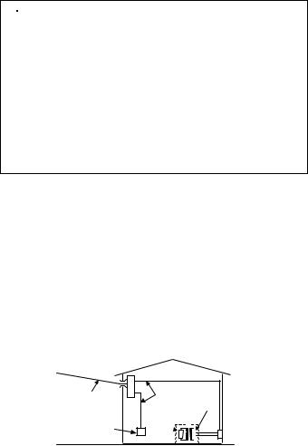
○Measurement categories (Over-voltage categories)
To ensure safe operation of measuring instruments, IEC61010 establishes safety standards for various electrical environments, categorized as CAT to CAT , and called measurement categories. Higher-numbered categories correspond to electrical environments with greater momentary energy, so a measuring instrument designed for CAT environments can endure greater momentary energy than one designed for CAT .
CAT : Secondary electrical circuits connected to an AC electrical outlet through a transformer or similar device.
CAT : Primary electrical circuits of equipment connected to an AC electrical outlet by a power cord.
CAT : Primary electrical circuits of the equipment connected directly to the distribution panel, and feeders from the distribution panel to outlets.
CAT :The circuit from the service drop to the service entrance, and to the power meter and primary over-current protection device (distribution panel).
Incoming wire
Interior wiring
CAT.IV |
CAT.III |
TransformerCAT.II
Socket CAT.I
― 3 ―

Features
KEW SNAP 2413F is a unique digital clamp meter for both very low current and high current measurements. Its shielded transformers jaws minimizes the effect of external stray magnetic field, enabling leakage current measurements.
●Measures from 0.1mA to 1000A AC and provides frequency response higher than 1kHz on all measuring ranges.
Measurements also possible with approximately 7% accuracy at 20 kHz on 200mA range.
●Provides a frequency selector switch ― 50/60Hz or WIDE ―to turn on or off an incorporated low pass filter. This permits current measurement in mains fundamental frequency only or a wide range of frequencies, including those from such devices as inverters.
●Peak-hold facility with selectable response time of 10ms or 100 ms. ●Two-way analogue output terminal
Provides AC voltage output proportional to the current under test for monitoring the waveform with an oscilloscope or measuring RMS current values with a true-RMS-reading instrument.
Also convent ACA readings to DC voltage output for direct connection to such devices as a chart recorder.
●Data hold function to allow for easy readings in hard-to-reach locations. Display can be observed away from the conductor.
― 4 ―

Specifications
Measuring Ranges and Accuracy
●AC Current
|
|
Accuracy |
|
||
Ranges |
|
|
Time Limit for |
||
Frequency Range Response |
|||||
Measurements |
|||||
|
|
|
|
||
|
|
WIDE |
50/60Hz |
|
|
|
|
|
|
|
|
200m |
0 199.9m |
±1.0 rdg±2dgt |
|
|
|
|
|
50/60Hz |
±1.5 rdg±2dgt |
|
|
2 |
0 1.999 |
|
|||
±3.0 rdg±2dgt |
|
||||
|
|
|
|
||
20 |
0 19.99 |
40 kHz |
|
|
|
|
|
|
|
|
|
|
|
±1.5 rdg±2dgt |
|
|
|
200 |
0 199.9 |
50/60Hz |
±2.0 rdg±2dgt |
Continuous |
|
±3.5 rdg±2dgt |
|||||
|
|
|
|
||
|
|
40 kHz |
|
|
|
|
|
|
|
|
|
|
|
±1.5 rdg±2dgt |
|
|
|
|
0 500 |
50/60Hz |
±2.0 rdg±2dgt |
|
|
|
±3.5 rdg±2dgt |
|
|||
|
|
|
|
||
|
|
40 kHz |
|
|
|
1000 |
|
|
|
|
|
|
±5 rdg |
|
|
||
|
|
|
|
||
|
501 1000 |
50/60Hz |
±5.5 rdg |
10min. |
|
|
±10 rdg |
||||
|
|
|
|
||
|
|
40 kHz |
|
|
|
|
|
|
|
|
|
Refer to Figure 1 for frequency characteristics.
●Effect of External Stray Magnetic Field
10mA AC max. in proximity to a 10mm-dia conductor carrying 100A
AC.
●Effect of Residual Current
10mA AC max. when clamping on two 10mm-dia conductors, each carrying supply or return 100A AC current.
― 5 ―

Analogue Output (Output impedance: Approx. 1kΩ)
●AC Output
Range |
Measuring Range |
AC Output Voltage |
Accuracy |
|
|
|
|
|
|
200mA |
0 200mA |
|
|
|
|
|
|
±2 rdg |
|
2A |
0 2A |
0 200mV |
||
|
|
|
||
20A |
0 20A |
|
||
|
|
|||
|
|
|
|
|
200A |
0 200A |
|
±2.5 rdg |
|
|
|
|
|
|
1000A |
0 500A |
0 50mV |
±3 rdg |
|
|
|
|
||
501A 1000A |
50 100mV |
±5 rdg |
||
|
||||
|
|
|
|
*Voltage proportional to the current under test is output with “WIDE”frequency characteristics regardless of the setting of the frequency Selector or peak hold switch.
― 6 ―
 Loading...