

Page 1

PF-470
PF-471
SERVICE
MANUAL
Published in October 2010
843NN110
3NNSM060
First Edition
Page 2

CAUTION
RISK OF EXPLOSION IF BATTERY IS REPLACED BY AN INCORRECT TYPE. DISPOSE
OF USED BATTERIES ACCORDING TO THE INSTRUCTIONS.
It may be illegal to dispose of this battery into the municipal waste stream. Check with your
local solid waste officials for details in your area for proper disposal.
ATTENTION
IL Y A UN RISQUE D’EXPLOSION SI LA BATTERIE EST REMPLACEE PAR UN MODELE
DE TYPE INCORRECT. METTRE AU REBUT LES BATTERIES UTILISEES SELON LES
INSTRUCTIONS DONNEES.
Il peut être illégal de jeter les batteries dans des eaux d’égout municipales. Vérifiez avec les
fonctionnaires municipaux de votre région pour les détails concernant des déchets solides
et une mise au rebut appropriée.
Page 3

Revision history
Revision Date Replaced pages Remarks
Page 4

This page is intentionally left blank.
Page 5

Safety precautions
This booklet provides safety warnings and precautions for our service personnel to ensure the safety of
their customers, their machines as well as themselves during maintenance activities. Service personnel
are advised to read this booklet carefully to familiarize themselves with the warnings and precautions
described here before engaging in maintenance activities.
Page 6
Safety warnings and precautions
Various symbols are used to protect our service personnel and customers from physical danger and
to prevent damage to their property. These symbols are described below:
DANGER: High risk of serious bodily injury or death may result from insufficient attention to or incorrect
compliance with warning messages using this symbol.
WARNING: Serious bodily injury or death may result from insufficient attention to or incorrect compliance
with warning messages using this symbol.
CAUTION: Bodily injury or damage to property may result from insufficient attention to or incorrect com-
pliance with warning messages using this symbol.
Symbols
The triangle ( ) symbol indicates a warning including danger and caution. The specific point of attention is
shown inside the symbol.
General warning. Warning of risk of electric shock.
Warning of high temperature.
indicates a prohibited action. The specific prohibition is shown inside the symbol.
General prohibited action. Disassembly prohibited.
indicates that action is required. The specific action required is shown inside the symbol.
General action required. Remove the power plug from the wall outlet.
Always ground the copier.
Page 7

1. Installation Precautions
WARNING
• Do not use a power supply with a voltage other than that specified. Avoid multiple connections to
one outlet: they may cause fire or electric shock. When using an extension cable, always check that
it is adequate for the rated current. .....................................................................................................
• Connect the ground wire to a suitable grounding point. Not grounding the copier may cause fire or
electric shock. Connecting the earth wire to an object not approved for the purpose may cause
explosion or electric shock. Never connect the ground cable to any of the following: gas pipes, lightning rods, ground cables for telephone lines and water pipes or faucets not approved by the proper
authorities. ..........................................................................................................................................
CAUTION:
• Do not place the copier on an infirm or angled surface: the copier may tip over, causing injury. .........
• Do not install the copier in a humid or dusty place. This may cause fire or electric shock. .................
• Do not install the copier near a radiator, heater, other heat source or near flammable material. This
may cause fire. ...................................................................................................................................
• Allow sufficient space around the copier to allow the ventilation grills to keep the machine as cool
as possible. Insufficient ventilation may cause heat buildup and poor copying performance. ............
• Always handle the machine by the correct locations when moving it. .................................................
• Always use anti-toppling and locking devices on copiers so equipped. Failure to do this may cause
the copier to move unexpectedly or topple, leading to injury. ..............................................................
• Avoid inhaling toner or developer excessively. Protect the eyes. If toner or developer is accidentally
ingested, drink a lot of water to dilute it in the stomach and obtain medical attention immediately.
If it gets into the eyes, rinse immediately with copious amounts of water and obtain medical atten-
tion. .....................................................................................................................................................
• Advice customers that they must always follow the safety warnings and precautions in the copier’s
instruction handbook. .........................................................................................................................
Page 8
2. Precautions for Maintenance
WARNING
• Always remove the power plug from the wall outlet before starting machine disassembly. ................
• Always follow the procedures for maintenance described in the service manual and other related
brochures. ..........................................................................................................................................
• Under no circumstances attempt to bypass or disable safety features including safety mechanisms
and protective circuits. ........................................................................................................................
• Always use parts having the correct specifications. ............................................................................
• Always use the thermostat or thermal fuse specified in the service manual or other related brochure
when replacing them. Using a piece of wire, for example, could lead to fire or other serious acci-
dent. ...................................................................................................................................................
• When the service manual or other serious brochure specifies a distance or gap for installation of a
part, always use the correct scale and measure carefully. ..................................................................
• Always check that the copier is correctly connected to an outlet with a ground connection. ...............
• Check that the power cable covering is free of damage. Check that the power plug is dust-free. If it
is dirty, clean it to remove the risk of fire or electric shock. .................................................................
• Never attempt to disassemble the optical unit in machines using lasers. Leaking laser light may
damage eyesight. ...............................................................................................................................
• Handle the charger sections with care. They are charged to high potentials and may cause electric
shock if handled improperly. ...............................................................................................................
CAUTION
• Wear safe clothing. If wearing loose clothing or accessories such as ties, make sure they are safely
secured so they will not be caught in rotating sections. ......................................................................
• Use utmost caution when working on a powered machine. Keep away from chains and belts. ..........
• Handle the fixing section with care to avoid burns as it can be extremely hot. ..................................
• Check that the fixing unit thermistor, heat and press rollers are clean. Dirt on them can cause
abnormally high temperatures. ...........................................................................................................
Page 9

• Do not remove the ozone filter, if any, from the copier except for routine replacement. ......................
• Do not pull on the AC power cord or connector wires on high-voltage components when removing
them; always hold the plug itself. ........................................................................................................
• Do not route the power cable where it may be stood on or trapped. If necessary, protect it with a
cable cover or other appropriate item. ................................................................................................
• Treat the ends of the wire carefully when installing a new charger wire to avoid electric leaks. ..........
• Remove toner completely from electronic components. .....................................................................
• Run wire harnesses carefully so that wires will not be trapped or damaged. ......................................
• After maintenance, always check that all the parts, screws, connectors and wires that were
removed, have been refitted correctly. Special attention should be paid to any forgotten connector,
trapped wire and missing screws. .......................................................................................................
• Check that all the caution labels that should be present on the machine according to the instruction
handbook are clean and not peeling. Replace with new ones if necessary. .......................................
• Handle greases and solvents with care by following the instructions below: ......................................
· Use only a small amount of solvent at a time, being careful not to spill. Wipe spills off completely.
· Ventilate the room well while using grease or solvents.
· Allow applied solvents to evaporate completely before refitting the covers or turning the power
switch on.
· Always wash hands afterwards.
• Never dispose of toner or toner bottles in fire. Toner may cause sparks when exposed directly to
fire in a furnace, etc. ...........................................................................................................................
• Should smoke be seen coming from the copier, remove the power plug from the wall outlet immedi-
ately. ...................................................................................................................................................
3. Miscellaneous
WARNING
• Never attempt to heat the drum or expose it to any organic solvents such as alcohol, other than the
specified refiner; it may generate toxic gas. ........................................................................................
Page 10

This page is intentionally left blank.
Page 11

CONTENTS
1-1 Specifications
1-1-1 Specifications ........................................................................................................................ 1-1-1
1-1-2 Parts names .......................................................................................................................... 1-1-2
(1) Paper feeder (single casette) ........................................................................................... 1-1-2
(2) Paper feeder (double casette) .......................................................................................... 1-1-3
1-1-3 Machine cross section ........................................................................................................... 1-1-4
(1) Paper feeder (single casette) ........................................................................................... 1-1-4
(2) Paper feeder (double casette) .......................................................................................... 1-1-4
1-2 Installation
1-2-1 Installation environment......................................................................................................... 1-2-1
1-2-2 Unpacking.............................................................................................................................. 1-2-2
(1) Unpacking Paper feeder (single casette) ........................................................................ 1-2-2
(2) Unpacking Paper feeder (double casette) ....................................................................... 1-2-3
(3) Removing the tapes.......................................................................................................... 1-2-4
1-3 Maintenance Mode
1-3-1 Maintenance mode ................................................................................................................ 1-3-1
(1) Executing a maintenance item ......................................................................................... 1-3-1
(2) Maintenance modes item list ............................................................................................ 1-3-2
(3) Contents of the maintenance mode items ........................................................................ 1-3-3
1-4 Troubleshooting
1-4-1 Paper misfeed detection ........................................................................................................ 1-4-1
(1) Paper misfeed indication .................................................................................................. 1-4-1
(2) Paper misfeed detection condition ................................................................................... 1-4-1
1-4-2 Self-diagnostic function ......................................................................................................... 1-4-4
(1) Self-diagnostic function .................................................................................................... 1-4-4
(2) Self diagnostic codes........................................................................................................ 1-4-4
1-4-3 Electric problems ................................................................................................................... 1-4-6
1-4-4 Mechanical problems............................................................................................................. 1-4-8
1-5 Assembly and disassembly
1-5-1 Precautions for assembly and disassembly........................................................................... 1-5-1
(1) Precautions....................................................................................................................... 1-5-1
1-5-2 Paper feed section................................................................................................................. 1-5-2
(1) Detaching and refitting the primary paper feed units........................................................ 1-5-2
(2) Detaching and refitting the drive unit ................................................................................ 1-5-3
(3) Detaching and refitting the PF main PWB ........................................................................ 1-5-4
2-1 Mechanical Construction
2-1-1 Mechanical construction ........................................................................................................ 2-1-1
(1) Paper feeder (single casette) ........................................................................................... 2-1-1
(2) Paper feeder (double casette) .......................................................................................... 2-1-2
2-2 Electrical Parts Layout
2-2-1 Electrical parts layout ............................................................................................................ 2-2-1
(1) Paper feeder (single casette) ........................................................................................... 2-2-1
(2) Paper feeder (double casette) .......................................................................................... 2-2-2
2-3 Operation of the PWBs
2-3-1 PF main PWB ........................................................................................................................ 2-3-1
2-4 Appendixes
2-4-1 Appendixes............................................................................................................................ 2-4-1
(1) Wiring diagram ................................................................................................................. 2-4-1
3NN/3NP
Page 12

3NN/3NP
This page is intentionally left blank.
Page 13

1-1 Specifications
1-1-1 Specifications
Item Specifications
Original feed method Paper feeder (single casette) Paper feeder (double casette)
Paper weight 52 to 163 g/m
Paper type Plain, Recycled, Color (Colour), Thick
2
3NN/3NP
Paper size
Loading capacity 500 sheets (80 g/m
Dimensions (W × D × H)
A3,A4R,A4, A5R, B5R,B5,Folio,Ledger, LetterR,Letter, Legal, Statement,
Executive, Oficio II, 8K, 16KR,16K
2
)
590 × 586 × 352 mm
23 1/4 × 23 7/16 × 13 7/8”
Weight 21 kg/ 46.3 lb or less 21 kg/ 46.3 lb or less
Power source Electrically connected to the machine.
NOTE: These specifications are subject to change without notice.
500 sheets (80 g/m
2
) × 2
1-1-1
Page 14
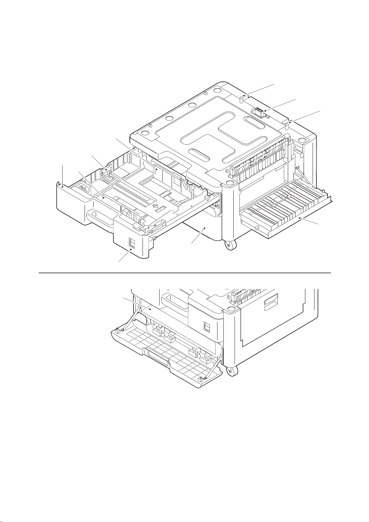
1-1-2 Parts names
8
6
7
1
4
5
2
4
6
3
9
1. Cassette 2
2. Paper type window
3. Box cover
4. Paper width guide
5. Paper length guide
6. Positioning pins
7. Interface connector
8. Right cover 3
9. Cabinet
(1) Paper feeder (single casette)
3NN/3NP
Figure 1-1-1
1-1-2
Page 15
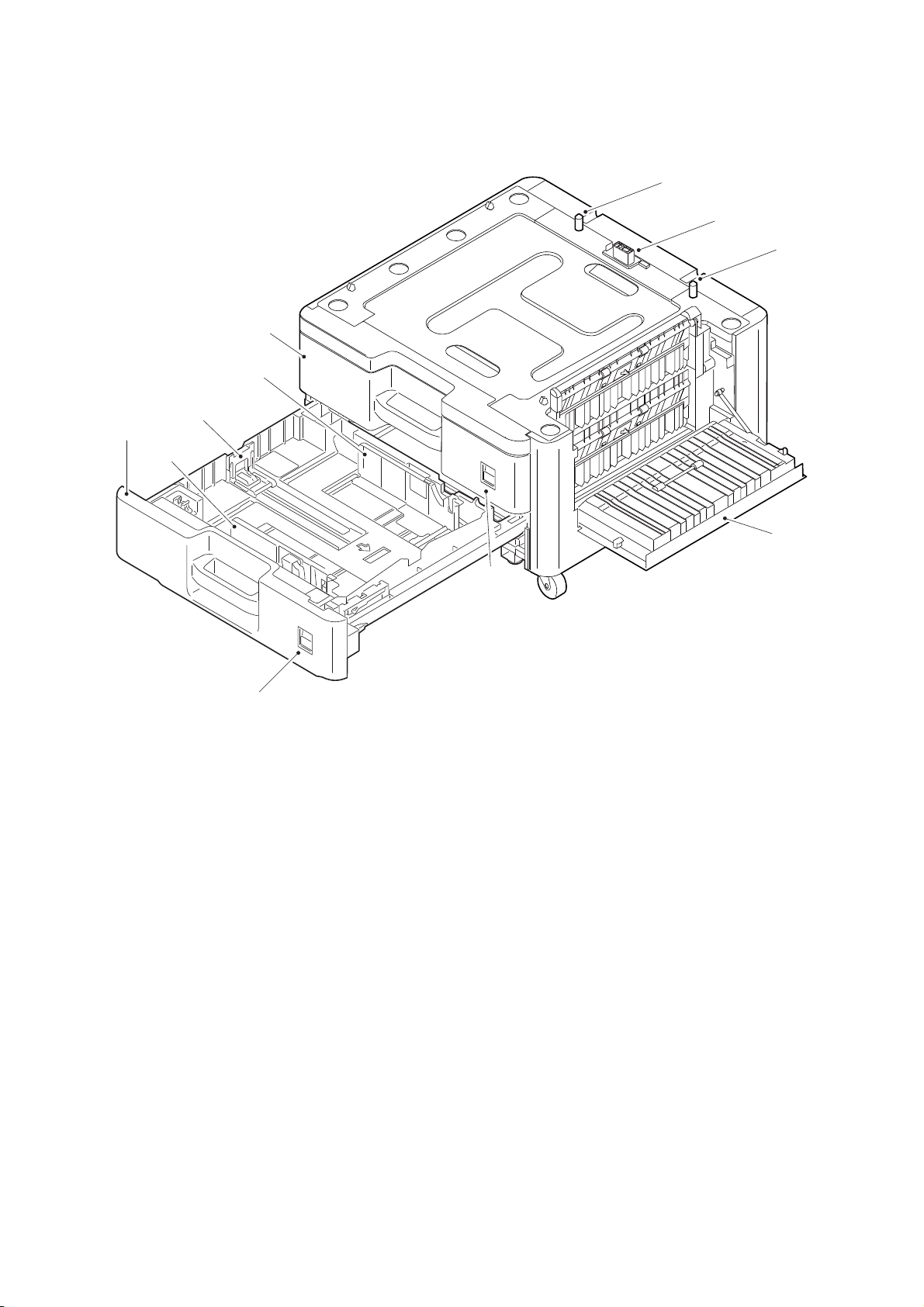
(2) Paper feeder (double casette)
8
6
7
2
4
5
1
3
3
4
6
1. Cassette 2
2. Cassette 3
3. Paper type window
4. Paper width guide
5. Paper length guide
6. Positioning pins
7. Interface connector
8. Right cover 3
3NN/3NP
Figure 1-1-2
1-1-3
Page 16
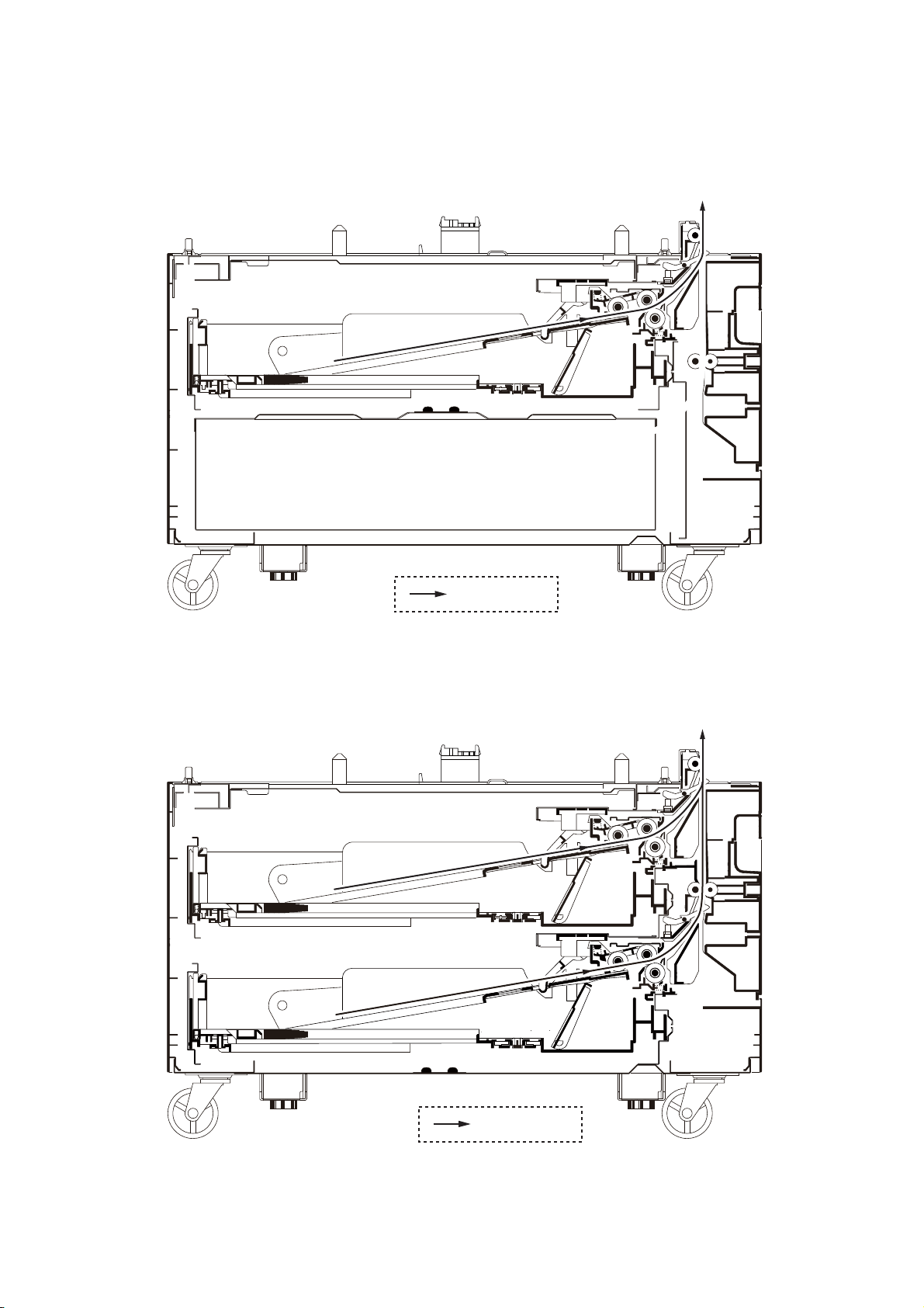
1-1-3 Machine cross section
Paper path
Paper path
(1) Paper feeder (single casette)
3NN/3NP
(2) Paper feeder (double casette)
Figure 1-1-3
Figure 1-1-4
1-1-4
Page 17

3NN/3NP
1-2 Installation
1-2-1 Installation environment
Installation location
Avoid direct sunlight or bright lighting. Ensure that the photoconductor will not be exposed to direct sunlight or
other strong light when removing paper jams.
Avoid locations subject to high temperature and high humidity or low temperature and low humidity; an abrupt
change in the environmental temperature; and cool or hot, direct air.
Avoid places subject to dust and vibrations.
Choose a surface capable of supporting the weight of the machine.
Place the machine on a level surface (maximum allowance inclination: 1°).
Avoid air-borne substances that may adversely affect the machine or degrade the photoconductor, such as
mercury, acidic of alkaline vapors, inorganic gasses, NOx, SOx gases and chlorine-based organic solvents.
Select a well-ventilated location.
1-2-1
Page 18
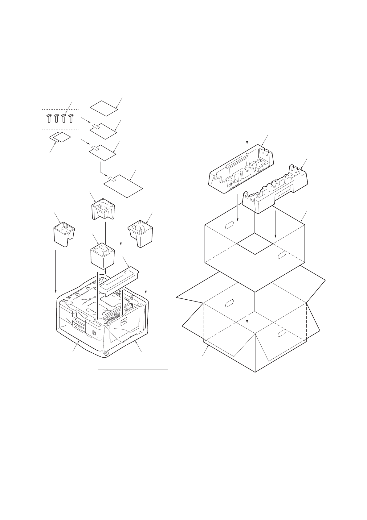
1-2-2 Unpacking
4
1
5
2
3
9
7
6
8
11
13
14
10
12
13
16
15
1. Paper feeder
2. Outer case
3. Inner case
4. Bottom left pad
5. Bottom right pad
6. Upper left front pad
7. Upper left back pad
8. Upper right front pad
9. Upper right back pad
10. Top spacer
11. Plastic sheet
12. Plastic bag (240 × 350)
13. Plastic bag (70 × 110)
14. Installation guide etc.
15. Cursor pins
16. Paper size plates
(1) Unpacking Paper feeder (single casette)
3NN/3NP
Figure 1-2-1
1-2-2
Page 19

(2) Unpacking Paper feeder (double casette)
1. Paper feeder
2. Outer case
3. Inner case
4. Bottom left pad
5. Bottom right pad
6. Upper left front pad
7. Upper left back pad
8. Upper right front pad
9. Upper right back pad
10. Top spacer
11. Plastic sheet
12. Plastic bag (240 × 350)
13. Plastic bag(70 × 110)
14. Installation guide etc.
15. Cursor pins
16. Paper size plates
3NN/3NP
16
15
7
6
8
13
13
10
14
12
4
5
9
3
Place the machine on a level surface.
1
11
Figure 1-2-2
1-2-3
2
Page 20

(3) Removing the tapes
Ta pe
Ta pe
Ta pe
Ta pe
1. Remove four tapes.
3NN/3NP
Figure 1-2-3
1-2-4
Page 21

3NN/3NP
Enter “10871087” using
the numeric keys.
Enter the maintenance item
number using the cursor left/right keys
or numeric keys.
The selected maintenance item is run.
Press the stop key.
Press the start key.
Start
End
Maintenance mode is entered.
The maintenance item is selected.
Maintenance mode is exited and
the system is restarted to initialize it
and to reflect the setting changes.
Repeat the same
maintenance item?
Run another maintenance
item?
Turn the main power switch off and on.
No
No
Yes
Yes
1-3 Maintenance Mode
1-3-1 Maintenance mode
The machine is equipped with a maintenance function which can be used to maintain and service the
machine.
(1) Executing a maintenance item
1-3-1
Page 22

(2) Maintenance modes item list
3NN/3NP
Section
General U019 Displaying the ROM version -
Drive, paper
feed and
paper conveying system
Mode setting U341 Specific paper feed location setting for printing function -
Others U901 Checking copy counts by paper feed locations -
Item
No.
U034 Adjusting the print start timing
Leading edge registration
Center line
U051 Adjusting the deflection in the paper 0/0/0/0
Content of maintenance item
Initial
setting
0/0/0/0/0/0
0/0/0/0/0
1-3-2
Page 23

(3) Contents of the maintenance mode items
Display Description
Main Main ROM
MMI Operation ROM
Engine Engine ROM
Engine Boot Engine booting
RFID RFID ROM
IO CPU IO CPU ROM
IO CPU Boot IO CPU booting
Option Language Optional language ROM
Dictionary -
DP Document processor ROM
DP Boot Document processor booting
PF Paper feeder ROM
PF Boot Paper feeder booting
DF Document finisher ROM
DF Boot Document finisher booting
AK Bridge ROM
AK Boot Bridge booting
Fax APL Fax control PWB APL
Fax Boot Fax control PWB booting
Fax IPL Fax control PWB IPL
Item No. Description
U019 Displaying the ROM version
Description
Displays the part number of the ROM fitted to each PWB.
Purpose
To check the part number or to decide, if the newest version of ROM is installed.
Method
1. Press the start key. The ROM version are displayed.
2. Change the screen using the cursor up/down keys.
3NN/3NP
Completion
Press the stop key. The screen for selecting a maintenance item No. is displayed.
1-3-3
Page 24

Item No. Description
Display Description
LSUOUT TOP Leading edge registration adjustment
LSUOUT LEFT Center line adjustment
Display Description
Setting
range
Initial
setting
Change in
value per step
MPT(L) Paper feed from MP tray
(when large size paper is used)
-128 to 127 0 0.1 mm
Cassette(L) Paper feed from cassette
(when large size paper is used)
-128 to 127 0 0.1 mm
Duplex(L) Duplex mode (second)
(when large size paper is used)
-128 to 127 0 0.1 mm
MPT(S) Paper feed from MP tray
(when small size paper is used)
-128 to 127 0 0.1 mm
Cassette(S) Paper feed from cassette
(when small size paper is used)
-128 to 127 0 0.1 mm
Duplex(S) Duplex mode (second)
(when small size paper is used)
-128 to 127 0 0.1 mm
U034 Adjusting the print start timing
Description
Adjusts the leading edge registration or center line.
Purpose
Make the adjustment if there is a regular error between the leading edges of the copy image and
original.
Make the adjustment if there is a regular error between the center lines of the copy image and
original.
Method
1. Press the start key.
2. Select the item to be adjusted.
3NN/3NP
Adjustment: Leading edge registration adjustment
1. Press the system menu key.
2. Press the start key to output a test pattern.
3. Press the system menu key.
4. Select the item to be adjusted..
Large size: 218 mm or more in width of paper.
1-3-4
Page 25

Item No. Description
Correct image
Output
example 1
Output
example 2
Leading edge
registration
(20 ± 1.5 mm)
U034
U066
(See the service manual
for the machine.)
U071
(See the service manual
for the machine.)
Display Description
Setting
range
Initial
setting
Change in
value per step
MPT Paper feed from MP tray -128 to 127 0 0.1 mm
Cassette1 Paper feed from cassette 1 -128 to 127 0 0.1 mm
Cassette2 Paper feed from optional
cassette 2
-128 to 127 0 0.1 mm
Cassette3 Paper feed from optional
cassette 3
-128 to 127 0 0.1 mm
Duplex Duplex mode (second) -128 to 127 0 0.1 mm
U034
5. Change the setting value using the cursor left/right keys or numeric keys.
For output example 1, increase the value. For output example 2, decrease the value.
Figure 1-3-1
6. Press the start key. The value is set.
Remark
When changing the setting value of [Large] each item is modified, equal to amount of the value
which is changed adds also the value of [Small] each item and is pulled.
3NN/3NP
Caution
Check the copy image after the adjustment. If the image is still incorrect, perform the following
adjustments in maintenance mode.
Adjustment: Center line adjustment
1. Press the system menu key.
2. Press the start key to output a test pattern.
3. Press the system menu key.
4. Select the item to be adjusted..
1-3-5
Page 26

Item No. Description
Center line of printing
(within ± 0.5 mm)
Correct image
Output
example 1
Output
example 2
U034
U067
(See the service manual
for the machine.)
U072
(See the service manual
for the machine.)
U034 5. Change the setting value using the cursor left/right keys or numeric keys.
For output example 1, increase the value. For output example 2, decrease the value.
Figure 1-3-2
6. Press the start key. The value is set.
3NN/3NP
Caution
Check the copy image after the adjustment. If the image is still incorrect, perform the following
adjustments in maintenance mode.
Completion
Press the stop key. The screen for selecting a maintenance item No. is displayed.
1-3-6
Page 27

Item No. Description
Display Description Setting range Initial setting
MPT Paper feed from MP tray -30 to 20 0
Cassette Paper feed from cassette 1 -30 to 20 0
PF Paper feed from paper feeder -30 to 20 0
Duplex Duplex mode (second) -30 to 20 0
Original Copy
example 1
Copy
example 2
U051 Adjusting the deflection in the paper
Description
Adjusts the deflection in the paper at the registration roller.
Purpose
Make the adjustment if the leading edge of the copy image is missing or varies randomly, or if the
copy paper is Z-folded.
Adjustment
1. Press the start key.
2. Press the system menu key.
3. Place an original and press the start key to make a test copy.
4. Press the system menu key.
5. Select the item to be adjusted.
3NN/3NP
6. Change the setting value using the cursor left/right keys or numeric keys.
For output example 1, increase the value. For output example 2, decrease the value.
The greater the value, the larger the deflection; the smaller the value, the smaller the deflection.
Figure 1-3-3
7. Press the start key. The value is set.
Completion
Press the stop key. The indication for selecting a maintenance item No. appears.
1-3-7
Page 28

Item No. Description
Display Description
Cassette1 Cassette 1
Cassette2 Cassette 2 (paper feeder)
Cassette3 Cassette 3 (paper feeder)
U341 Specific paper feed location setting for printing function
Description
Sets a paper feed location specified for printer output (only if a printer kit is installed).
Purpose
To use a paper feed location only for printer output.
A paper feed location specified for printer output cannot be used for copy output.
Method
1. Press the start key.
2. Select the paper feed location for the printer.
3. Select [On] or [Off] using the cursor left/right keys.
* : When an optional paper feed device is not installed, the corresponding count is not dis-
played.
4. Press the start key. The setting is set.
3NN/3NP
Completion
Press the stop key. The screen for selecting a maintenance item No. is displayed.
1-3-8
Page 29

Item No. Description
Display Description
MPT MP tray
Cassette1 Cassette 1
Cassette2 Cassette 2 (paper feeder)
Cassette3 Cassette 3 (paper feeder)
Duplex Duplex unit
U901 Checking copy counts by paper feed locations
Description
Displays or clears copy counts by paper feed locations.
Purpose
To check the time to replace consumable parts. Also to clear the counts after replacing the consumable parts.
Method
1. Press the start key. The counts by paper feed locations are displayed.
3NN/3NP
* : When an optional paper feed device is not installed, the corresponding count is not dis-
played.
Clearing
1. Select the counts to be cleared.
[Cassette2] and [Cassette3] cannot be cleared.
2. Select the counts for all and press [Clear].
3. Press the start key. The counter value is cleared.
Completion
Press the stop key. The screen for selecting a maintenance item No. is displayed.
1-3-9
Page 30

3NN/3NP
This page is intentionally left blank.
1-3-10
Page 31

3NN/3NP
Sensors
Regist sensor
PF paper feed sensor1
PF paper feed sensor2
Feed sensor
MP paper feed sensor
Eject sensor
Paper full sensor
1
2
3
4
5
6
7
DP paper feed sensor
DP timing sensor
DP regist sensor
DP switchback sensor
Eject paper sensor
Duplex sensor
10
11
12
13
8
9
Paper jam location
MP tray
Cassette1
Cassette2
Cassette3
Machine inside
Duplex section
Right cover2
Job separatot tray
Bridge
Document finsher
DP original tray
DP paper feed section
DP feed section
DP switchback section
A
B
C
D
E
F
G
H
A
B
C
D
E
F
G
H
1
2
3
4
5
6
7
Document processor
Machine
Paper
feeder
J
K
L
M
N
P
J
K
L
M
N
12
P
8
9
13
10
11
Document
Fisher
1-4 Troubleshooting
1-4-1 Paper misfeed detection
(1) Paper misfeed indication
When a paper misfeed occurs, the machine immediately stops printing and displays the paper misfeed message on the operation panel. To remove paper misfed in the machine, pull out the cassette, open the right
cover.
(2) Paper misfeed detection condition
Figure 1-4-1 Paper jam location
1-4-1
Page 32

3NN/3NP
Code Contents Conditions
0502 No paper feed from cassette 2PF feed sensor 1 (PFFS1) does not turn on during
paper feed from cassette 2 (Retry 1 times).
0503 No paper feed from cassette 3PF feed sensor 2 (PFFS2) does not turn on during
paper feed from cassette 3 (Retry 1 times).
0512 Multiple sheets in cassette 2 PF feed sensor 1 (PFFS1) does not turn off during
paper feed from cassette 2.
0513 Multiple sheets in cassette 3 PF feed sensor 2 (PFFS2) does not turn off during
paper feed from cassette 3.
1403 PF feed sensor 1 non arrival
jam
1413 PF feed sensor 1 stay jam PF feed sensor 1 (PFFS1) does not turn off during
4002 Registration sensor non
arrival jam
4003 The registration sensor (RS) does not turn on dur-
4012 Registration sensor stay jam The registration sensor (RS) does not turn off dur-
PF feed sensor 1 (PFFS1) does not turn on during
paper feed from cassette 3.
paper feed from cassette 3.
The registration sensor (RS) does not turn on during paper feed from cassette 2.
ing paper feed from cassette 3.
ing paper feed from cassette 2.
Jam
location*
B
C
B
C
E
E
E
E
E
4013 The registration sensor (RS) does not turn off dur-
ing paper feed from cassette 3.
4202 Eject sensor non arrival jam The eject sensor (ES) does not turn on during
paper feed from cassette 2.
4203 The eject sensor (ES) does not turn on during
paper feed from cassette 3.
4212 Eject sensor stay jam The eject sensor (ES) does not turn off during
paper feed from cassette 2.
4213 The eject sensor (ES) does not turn off during
paper feed from cassette 3.
4302 Duplex sensor non arrival
jam
4303 The duplex sensor (DUS) does not turn on during
4312 Duplex sensor stay jam The duplex sensor (DUS) does not turn off during
4313 The duplex sensor (DUS) does not turn off during
4902 Bridge conveying sensor 1
non arrival jam
The duplex sensor (DUS) does not turn on during
paper feed from cassette 2.
paper feed from cassette 3.
paper feed from cassette 2.
paper feed from cassette 3.
The bridge conveying sensor 1 (BRCS1) does not
turn on during paper feed from cassette 2.
E
F
F
F
F
F
F
G
G
F
4903 The bridge conveying sensor 1 (BRCS1) does not
turn on during paper feed from cassette 3.
*: Refer to figure 1-4-2 for paper jam location (see page 1-4-1).
1-4-2
F
Page 33

3NN/3NP
Code Contents Conditions
4912 Bridge conveying sensor 1
stay jam
4913 The bridge conveying sensor 1 (BRCS1) does not
5002 Bridge conveying sensor 3
non arrival jam
5003 The bridge conveying sensor 3 (BRCS3) does not
5012 Bridge conveying sensor 3
stay jam
5013 The bridge conveying sensor 3 (BRCS3) does not
*: Refer to figure 1-4-2 for paper jam location (see page 1-4-1).
The bridge conveying sensor 1 (BRCS1) does not
turn off during paper feed from cassette 2.
turn off during paper feed from cassette 3.
The bridge conveying sensor 3 (BRCS3) does not
turn on during paper feed from cassette 2.
turn on during paper feed from cassette 3.
The bridge conveying sensor 3 (BRCS3) does not
turn off during paper feed from cassette 2.
turn off during paper feed from cassette 3.
Jam
location*
J
J
J
J
J
J
1-4-3
Page 34

3NN/3NP
1-4-2 Self-diagnostic function
(1) Self-diagnostic function
This machine is equipped with self-diagnostic function. When a problem is detected, the machine stops printing and display an error message on the operation panel. An error message consists of a message prompting
a contact to service personnel and a four-digit error code indicating the type of the error.
(2) Self diagnostic codes
If the part causing the problem was not supplied, use the unit including the part for replacement.
Code Contents Causes
1020 PF lift motor error
(paper feeder)
After cassette 2 is inserted,
PF lift sensor 1 does not turn
on within 12 s. This error is
detected four times successively.
1030 PF lift motor error
(paper feeder)
After cassette 3 is inserted,
PF lift sensor 2 does not turn
on within 12 s. This error is
detected four times successively.
Defective bottom
plate elevation
mechanism in the
cassette.
Defective connector cable or poor
contact in the connector.
Defective drive
transmission system of the PF lift
motor 1.
Defective PF lift
motor 1.
Defective PF main
PWB.
Defective bottom
plate elevation
mechanism in the
cassette.
Defective connector cable or poor
contact in the connector.
Check procedures/
corrective measures
Check to see if the bottom plate can move
smoothly and repair it if any problem is
found.
Reinsert the connector. Also check for continuity within the connector cable. If none,
replace the cable.
PF lift motor 1 and PF main PWB (YC4)
Check if the gears rotate smoothly. If not,
grease the bushes and gears. Check for
broken gears and replace if any.
Replace the PF lift motor 1.
Replace the PF main PWB (Refer to the service manual for the paper feeder).
Check to see if the bottom plate can move
smoothly and repair it if any problem is
found.
Reinsert the connector. Also check for continuity within the connector cable. If none,
replace the cable.
PF lift motor 2 and PF main PWB (YC7)
Defective drive
transmission system of the PF lift
motor 2.
Defective PF lift
motor 2.
Defective PF main
PWB.
1-4-4
Check if the gears rotate smoothly. If not,
grease the bushes and gears. Check for
broken gears and replace if any.
Replace the PF lift motor 2.
Replace the PF main PWB (Refer to the service manual for the paper feeder).
Page 35

3NN/3NP
Code Contents Causes
1800 Paper feeder communica-
tion error
A communication error is
detected 10 times in succession.
1900 Paper feeder EEPROM error
When writing the data, the
write data and the read data is
not continuously in agreement
5 times.
2600 PF drive motor error
(paper feeder)
When the PF drive motor is
driven, error signal is detected
continuously for 1 s.
Improper installation paper feeder.
Defective connector cable or poor
contact in the connector.
Defective engine
PWB.
Defective PF main
PWB.
Defective PF main
PWB.
Device damage of
EEPROM.
Defective connector cable or poor
contact in the connector.
Defective drive
transmission system of the PF drive
motor.
Check procedures/
corrective measures
Follow installation instruction carefully again.
Reinsert the connector. Also check for continuity within the connector cable. If none,
replace the cable.
PF main PWB (YC3) and engine PWB
(YC20)
Replace the engine PWB and check for correct operation.
Replace the PF main PWB (Refer to the service manual for the paper feeder).
Replace the PF main PWB (Refer to the service manual for the paper feeder).
Contact the Service Administrative Division.
Reinsert the connector. Also check for continuity within the connector cable. If none,
replace the cable.
PF drive motor and PF main PWB (YC2)
Check if the rollers and gears rotate
smoothly. If not, grease the bushes and
gears. Check for broken gears and replace if
any.
Defective PF drive
motor.
Defective PF main
PWB.
Replace the PF drive motor.
Replace the PF main PWB (Refer to the service manual for the paper feeder).
1-4-5
Page 36

1-4-3 Electric problems
If the part causing the problem was not supplied, use the unit including the part for replacement.
Troubleshooting to each failure must be in the order of the numbered symptoms.
Problem Causes Check procedures/corrective measures
3NN/3NP
(1)
The machine does
not operate when
the main power
switch is turned on.
(2)
PF paper feed
clutch 1 and 2
does not operate.
(3)
PF conveying
clutch does not
operate.
1. No electricity at the
power outlet.
2. The power cord is
not plugged in properly.
3. The right cover 3 is
not closed completely.
4. Broken power cord. Check for continuity. If none, replace the cord.
5. Defective PWB. Replace the PFmain PWB (see page 1-5-4).
1. Defective connector
cable or poor contact in the connector.
2. Defective clutch. Replace the drive unit.
3. Defective PWB. Replace the PFmain PWB and check for correct operation
1. Defective connector
cable or poor contact in the connector.
2. Defective clutch. Replace the PF conveying clutch.
Measure the input voltage.
Check the contact between the power plug and the outlet.
Check the right cover 3.
Reinsert the connector. Also check for continuity within the
connector cable. If none, replace the cable.
Paper feed clutch 1 and PFmain PWB (YC4)
Paper feed clutch 2 and PFmain PWB (YC7)
(see page 1-5-4).
Reinsert the connector. Also check for continuity within the
connector cable. If none, replace the cable.
PF conveying clutch and PFmain PWB (YC4)
(4)
The message
requesting paper to
be loaded is shown
when paper is
present on the cassette.
3. Defective PWB. Replace the PFmain PWB and check for correct operation
(see page 1-5-4).
1. Defective connector
cable or poor contact in the connector.
2. Deformed actuator of
the paper sensor.
3. Defective paper sensor 1 and 2.
4. Defective PWB. Replace the PFmain PWB and check for correct operation
Reinsert the connector. Also check for continuity within the
connector cable. If none, replace the cable.
Paper sensor 1 and PFmain PWB (YC3)
Paper sensor 2 and PFmain PWB (YC6)
Check visually and replace if necessary.
Replace paper sensor 1 and 2.
(see page 1-5-4).
1-4-6
Page 37

Problem Causes Check procedures/corrective measures
3NN/3NP
(5)
The size of paper
on the cassette is
not displayed correctly.
(6)
A paper jam in the
paper feeder is
indicated when the
main power switch
is turned on.
(7)
A message indicating cover open is
displayed when the
right cover 3 is
closed.
1. Defective connector
cable or poor contact in the connector.
2. Defective PF paper
size switch.
3. Defective PWB. Replace the PFmain PWB PWB and check for correct
1. A piece of paper torn
from paper is caught
around PF feed sensor 1 or 2.
2. Defective PF feed
sensor 1 or 2.
1. Defective right cover
3 switch.
2. Defective PWB. Replace the PFmain PWB PWB and check for correct
Reinsert the connector. Also check for continuity within the
connector cable. If none, replace the cable.
PF paper size length switch 1 and PFmain PWB (YC5)
PF paper size length switch 2 and PFmain PWB (YC6)
PF paper size width switch 1 and PFmain PWB (YC5)
PF paper size width switch 2 and PFmain PWB (YC8)
Replace PF paper size switch.
operation (see page 1-5-4).
Check visually and remove it, if any.
Replace PF feed sensor 1 or 2.
Replace right cover 3 switch.
operation (see page 1-5-4).
1-4-7
Page 38

1-4-4 Mechanical problems
If the part causing the problem was not supplied, use the unit including the part for replacement.
Problem Causes/check procedures Corrective measures
3NN/3NP
(1)
No primary paper
feed.
(2)
Skewed paper feed.
(3)
Multiple sheets of
paper are fed.
(4)
Paper jams.
(5)
Abnormal noise is
heard.
Check if the surfaces of the following rollers are dirty with paper powder.
Pickup roller
Paper feed roller
Check if the following rollers is deformed.
Pickup roller
Paper feed roller
Defective paper feed clutch installation. Check visually and remedy if necessary.
Paper width guide in a cassette installed
incorrectly.
Check if the paper is excessively curled. Change the paper.
Paper is loaded incorrectly. Load the paper correctly.
Check if the retard roller is worn. Replace the retard roller if it is worn
Check if the paper is excessively curled. Change the paper.
Deformed guides along the paper conveying path.
Check if the rollers, pulleys and gears
operate smoothly.
Check if the following clutches are
installed correctly.
PF paper feed clutch 1
PF paper feed clutch 2
PF conveying clutch
Clean with isopropyl alcohol.
Check visually and replace any
deformed (see page 1-5-2).
Check the paper width guide visually
and remedy or replace if necessary.
(see page 1-5-2).
Check visually and remedy or replace
any deformed guides.
Grease the bushes and gears.
Check visually and remedy if necessary.
1-4-8
Page 39

3NN/3NP
1-5 Assembly and disassem bly
1-5-1 Precautions for assembly and disassembly
(1) Precautions
Before starting disassembly, press the Power key on the operation panel to off. Make sure that the Power
lamp is off before turning off the main power switch. And then unplug the power cable from the wall outlet.
When handling PWBs (printed wiring boards), do not touch parts with bare hands.
The PWBs are susceptible to static charge.
Do not touch any PWB containing ICs with bare hands or any object prone to static charge.
When removing the hook of the connector, be sure to release the hook.
Take care not to get the cables caught.
To reassemble the parts, use the original screws. If the types and the sizes of screws are not known, refer to
the PARTS LIST.
1-5-1
Page 40

1-5-2 Paper feed section
Cassette
p
p
(1) Detaching and refitting the primary paper feed units
Procedure
1. Remove cassette.
3NN/3NP
2. Push up the paper feed lever (yellow)
and then remove the primary paper
feed unit.
Figure 1-5-1
Paper feed lever
(yellow)
Primary paper feed unit
1-5-2
Figure 1-5-2
Page 41

(2) Detaching and refitting the drive unit
Rear cover
Screw
Screw
Hook(rear side)
Procedure
1. Remove two screws.
2. Release three hooks and then remove
the rear cover.
3NN/3NP
3. Remove the connector of the motor.
4. Release the wire from hooks.
5. Remove three screws and then remove
the drive unit.
Screw
Screw
Screw
Motor
Connector
Drive unit
Figure 1-5-3
Hook
Wire
Hook
Hook
Figure 1-5-4
1-5-3
Page 42

(3) Detaching and refitting the PF main PWB
Procedure
1. Remove the rear cover.
2. Remove all connectors from the PF
main PWB.
3. Remove two screws.
4. Release two hooks and then remove
the PF main PWB.
PF main PWB
3NN/3NP
Hook
Screw
Screw
PF main PWB
Figure 1-5-5
1-5-4
Page 43

3NN/3NP
1. Pickup roller
2. Paper feed roller
3. Retard roller
4. Feed roller 1
5. PF lift sensor 1 (PFLS1)
6. Cassette base
7. Bottom plate
8. Bottom pad
9. Lift work plate
10. Paper sensor 1(U) (PFPS1(U))
11. Paper sensor 1(L) (PFPS1(L))
12. Actuator (paper sensor 1)
13. PF feed sensor 1
14. Actuator (PF feed sensor 1)
2-1 Mechanical Construction
2-1-1 Mechanical construction
The paper feeder feeds paper from either of its one or two cassettes to the machine.The cassette can contain
500 sheets (80 g/m
paper conveying section by rotation of the paper feed roller. Also the retard roller prevents multiple feeding of
paper.
(1) Paper feeder (single casette)
2
) . The sheet from the cassette is pulled out by rotation of the pickup roller and sent to the
4
2
14
5
1
13
11
10
12
7
3
8
9
6
Figure 2-1-1 Paper feeder (single casette)
2-1-1
Page 44

(2) Paper feeder (double casette)
5
2
3
6
9
10
11
1
17
20
21
2
1
3
9
10
11
12
12
18
19
22
4
13
14
15
16
7
8
1. Pickup roller
2. Paper feed roller
3. Retard roller
4. Feed roller 1
5. Feed roller 2
6. Feed pulley
7. PF lift sensor 1 (PFLS1)
8. PF lift sensor 2 (PFLS2)
9. Cassette base
10. Bottom plate
11. Bottom pad
12. Lift work plate
13. Paper sensor 1(U) (PFPS1(U))
14. Paper sensor 1(L) (PFPS1(L))
15. Paper sensor 2(U) (PFPS2(U))
16. Paper sensor 2(L) (PFPS2(L))
17. Actuator (paper sensor 1)
18. Actuator (paper sensor 2)
19. PF feed sensor 1
20. PF feed sensor 2
21. Actuator (PF feed sensor 1)
22. Actuator (PF feed sensor 2)
3NN/3NP
Figure 2-1-2 Paper feeder (double casette)
2-1-2
Page 45

PFMPWB
YC4-6
3NN/3NP
REG_CL_REM
YC3-12
YC4-3
YC3-3
YC3-6
YC3-9
YC4-1
YC5-1,2,4
YC5-5
YC6-3*
YC6-6*
YC6-9*
YC7-1*
YC8-1,2,4*
YC8-5*
PFFS1
REG_CL_REM1
PFLS1
PFPS1(U)
PFPS1(L)
LIFT_REM1
PAPLSIZE1(1),(2),(3)
PAPWSIZE1
PFLS2
PFPS2(U)
PFPS2(L)
LIFT_REM2
PAPLSIZE2(1),(2),(3)
PAPWSIZE2
PFPLSW1
PFPLSW2
PFPS1(U)
PFPS1(L)
PFPWSW1
PFPS2(U)
PFPS2(L)
PFPWSW2
5
PFLS1
PFLM1
PFLS2
PFLM2
PFDM
PFPF
CL1
PFPF
CL2
PFFS1
5
PFFS2
PFC
CL
YC2-4
YC7-3*
YC6-12*
MAIN_REM
REG_CL_REM2
PFFS2
*: Paper feeder (double casette) only.
Figure 2-1-3
2-1-3
Page 46

3NN/3NP
This page is intentionally left blank.
2-1-4
Page 47

2-2 Electrical Parts Layout
2
3
4
5
6
7
8
9
10
11
13
Machine insideMachine front
Machine rear
1
12
2-2-1 Electrical parts layout
(1) Paper feeder (single casette)
3NN/3NP
Figure 2-2-1 PWBs
1. PF main PWB (PFMPWB) .................... Controls electrical parts.
2. Right cover 3 switch (RC3SW) ............. Breaks the safety circuit when right cover 3 is opened, and resets
paper jam detection.
3. PF lift sensor 1 (PFLS1)....................... Detects the cassette operation plate of cassette 2 reaching the
upper limit.
4. PF paper sensor 1 (U)(PFPS1(U))....... Detects the presence of paper in cassette 2.
5. PF paper sensor 1 (L)(PFPS1(L))........ Detects the presence of paper in cassette 2.
6. PF paper size length switch 1
(PFPLSW1)........................................... Detects the length of paper in cassette 2.
7. PF paper size width switch 1
(PFPWSW1) ......................................... Detects the width of paper in cassette 2.
8. PF feed sensor1 (PFFS1) ..................... Detects the presence of paper.
9. PF drive motor (PFDM)......................... Drives the paper feeder.
10. PF lift motor 1 (PFLM1)......................... Drives the cassette operation plate of cassette 2.
11. PF paper feed clutch 1 (PFPFCL1)....... Primary paper feed from cassette 2.
12. PF paper conveying clutch (PFCCL) .... Conveys paper to the machine.
13. PF cassette heater (PFCH)................... Dehumidifies paper.
2-2-1
Page 48

(2) Paper feeder (double casette)
2
3
5
4
7
8
6
9
10
11
12
13
15
17
19
20
21
1
16
14
18
Machine insideMachine front
Machine rear
3NN/3NP
Figure 2-2-2 Switches and sensors
1. PF main PWB (PFMPWB) .................... Controls electrical parts.
2. Right cover 3 switch (RC3SW) ............. Breaks the safety circuit when right cover 3 is opened, and resets
paper jam detection.
3. PF lift sensor 1 (PFLS1)........................ Detects the cassette operation plate of cassette 2 reaching the
upper limit.
4. PF lift sensor 2 (PFLS2)........................ Detects the cassette operation plate of cassette 3 reaching the
upper limit.
5. PF paper sensor 1 (U)(PFPS1(U))........ Detects the presence of paper in cassette 2.
6. PF paper sensor 1 (L)(PFPS1(L))......... Detects the presence of paper in cassette 2.
7. PF paper sensor 2 (U)(PFPS2(U))........ Detects the presence of paper in cassette 3.
8. PF paper sensor 2 (L)(PFPS2(L))......... Detects the presence of paper in cassette 3.
9. PF paper size length switch 1
(PFPLSW1)........................................... Detects the length of paper in cassette 2.
10. PF paper size length switch 2
(PFPLSW2)........................................... Detects the length of paper in cassette 3.
11. PF paper size width switch 1
(PFPWSW1) ......................................... Detects the width of paper in cassette 2.
12. PF paper size width switch 2
(PFPWSW2) ......................................... Detects the width of paper in cassette 3.
13. PF feed sensor 1 (PFFS1) .................... Detects the presence of paper.
14. PF feed sensor 2 (PFFS2) .................... Detects the presence of paper.
15. PF drive motor (PFDM)......................... Drives the paper feeder.
2-2-2
Page 49

16. PF lift motor 1 (PFLM1)......................... Drives the cassette operation plate of cassette 2.
17. PF lift motor 2 (PFLM2)......................... Drives the cassette operation plate of cassette 3.
18. PF paper feed clutch 1 (PFPFCL1)....... Primary paper feed from cassette 2.
19. PF paper feed clutch 2 (PFPFCL2)....... Primary paper feed from cassette 3.
20. PF paper conveying clutch (PFCCL) .... Conveys paper to the machine.
21. PF cassette heater (PFCH)................... Dehumidifies paper.
3NN/3NP
2-2-3
Page 50

3NN/3NP
This page is intentionally left blank.
2-2-4
Page 51

2-3 Operation of the PWBs
2-3-1 PF main PWB
112
YC1
12
5
6
3NN/3NP
YC7
8
U4
YC2
6
U1
7118
1
17
YC9
YC6
YC5
1
2
14
13
1
2
YC4
1
2
11
12
YC3
2
1
U2
1
Figure 2-3-1 PF main PWB silk-screen diagram
U3
YC8
6
2-3-1
Page 52

Connector Pin Signal I/O Voltage Description
YC1 1
GND
-
-
Ground
3NN/3NP
Connected to
the.interface
connector
YC2 1
Connected to
the PF drive
motor.
GND
2
3.3V4
3
3.3V0
4
24V4
5
PF_PAUSE
6
PF_SET
7
PF_RDY
8
PF_SEL
9
EH_SI
10
EH_SO
11
EH_CLK
12
MAIN_DIR
MAIN_READY
2
MAIN_CLK
3
MAIN_REM
4
GND
5
-
-
DC3.3V
I
DC3.3V
I
DC24V
I
DC0V/3.3V
O
DC0V/3.3V
O
DC0V/3.3V
O
DC0V/3.3V
I
DC0V/3.3V(pulse)
I
DC0V/3.3V(pulse)
O
DC0V/3.3V(pulse)
I
DC0V/3.3V
O
DC0V/3.3V
I
DC0V/3.3V(pulse) Clock signal to PFDM
O
DC0V/3.3V PFDM: On/Off
O
-
-
Ground
3.3V DC power from DFRPWB
3.3V DC power from DFRPWB
24 V DC power from DFRPWB
Pause signal
Set signal to the machine
Ready signal to the machine
Paper feeder select signal
Serial communication data signal input
Serial communication data signal output
Serial communication clock signal
Drive select signal to PFDM
Ready signal
Ground
YC3 1
Connected to
e PF paper
th
sensor 1(U)/
(L) , PF lift
sensor 1 and
PF feed sensor 1.
6
2
3
4
5
6
7
8
9
10
11
12
24V4
3.3V4
GND
PFLS1
3.3V4
GND
PFPS1(U)
3.3V4
GND
PFPS1(L)
3.3V4
GND
PFFS1
DC24V 24V DC power to PFDM
O
DC3.3V 3.3V DC power to PFLS1
O
- Ground
-
DC0V/3.3V PFLS1: On/Off
I
DC3.3V 3.3V DC power to PFPS1(U)
O
- Ground
-
DC0V/3.3V PFPS1(U): On/Off
I
DC3.3V 3.3V DC power to PFPS1(L)
O
- Ground
-
DC0V/3.3V PFPS1(L): On/Off
I
DC3.3V 3.3V DC power to PFFS1
O
- Ground
-
DC0V/3.3V PFFS1: On/Off
I
2-3-2
Page 53

Connector Pin Signal I/O Voltage Description
YC4 1
Connected to
the PF lift
motor 1, PF
paper feed
clutch 1 and
PF paper
conveying
clutch.
LIFT_REM1
24V4
2
REG_CL_RE
3
M1
NC
4
24V4
5
REG_CL_RE
6
M
DC0V/3.3V PFLM1: On/Off
O
DC24V 24V DC power to PFLM1
O
DC0V/3.3V PFPFCL1: On/Off
O
-
-
DC24V 24V DC power to PFPFCL1
O
DC0V/3.3V PFCCL: On/Off
O
Not used
3NN/3NP
YC5 1
Connected to
the PF paper
size length
switch 1, PF
paper size
width switch
1 and right
cover 3.
YC6 1
Connected to
the PF paper
sensor 2(U)/
(L), PF lift
sensor 2 and
PF feed sensor 2.
NC
7
24V4
8
PAPLSIZE1(3)
PAPLSIZE1(2)
2
GND
3
PAPLSIZE1(1)
4
PAPWSIZE1
5
GND
6
COVEROPEN
7
GND
8
3.3V4
GND
2
PFLS2
3
3.3V4
4
GND
5
PFPS2(U)
6
3.3V4
7
GND
8
PFPS2(L)
9
3.3V4
10
GND
11
PFFS2
12
NC
13
GND
14
-
-
DC24V 24V DC power to PFCCL
O
DC0V/3.3V PFPLSW1: On/Off
I
DC0V/3.3V PFPLSW1: On/Off
I
-
-
DC0V/3.3V PFPLSW1: On/Off
I
DC0V/3.3V PFPWSW1: On/Off
I
-
-
DC0V/3.3V RC3SW: On/Off
I
-
-
DC3.3V 3.3V DC power to PFLS2
O
- Ground
-
0V/3.3V PFLS2: On/Off
DC
I
DC3.3V 3.3V DC power to PFPS2(U)
O
- Ground
-
DC0V/3.3V PFPS2(U): On/Off
I
DC3.3V 3.3V DC power to PFPS2(L)
O
- Ground
-
DC0V/3.3V PFPS2(L): On/Off
I
DC3.3V 3.3V DC power to PFFS2
O
- Ground
-
DC0V/3.3V PFFS2: On/Off
I
- Not used
-
- Ground
-
Not used
Ground
Ground
Ground
2-3-3
Page 54

Connector Pin Signal I/O Voltage Description
YC7 1
Connected to
the PF lift
motor 2 and
PF paper
feed clutch 1.
YC8 1
Connected to
the PF paper
size length
switch 2 and
PF paper
size width
switch 2.
LIFT_REM2
24V4
2
REG_CL_RE
3
M2
NC
4
24V4
5
PAPLSIZE2(3)
PAPLSIZE2(2)
2
GND
3
PAPLSIZE2(1)
4
PAW L S IZE2
5
GND
6
DC0V/24V PFLM2: On/Off
O
DC24V 24V DC power to PFLM2
O
DC0V/24V PFPFCL2: On/Off
O
-
-
DC24V 24V DC power to PFPFCL2
O
DC0V/3.3V PFPLSW2: On/Off
I
DC0V/3.3V PFPLSW2: On/Off
I
-
-
DC0V/3.3V PFPLSW2: On/Off
I
DC0V/3.3V PFPWSW2: On/Off
I
-
-
Not used
Ground
Ground
3NN/3NP
2-3-4
Page 55

2-4 Appendixes
2-4-1 Appendixes
(1) Wiring diagram
3NN/3NP
Machine
EPWB
EH_CLK
EH_SI
EH_SO
PF_SEL
PF_RDY
PF_SET
PF_PAUSE
24V4
3.3V0
3.3V4
GND
GND
PSPWB
Cassette_H_LIVE
Cassette_H_NEUTRAL
Cassette_H_LIVE
Cassette_H_NEUTRAL
NC
NC
1
1
2
2
3
3
4
4
5
5
6
6
7
7
8
8
9
9
10
10
11
11
12
12
1
1
5
5
3
4
2
2
6
6
AC_NEUTRAL
1
2
AC_LIVE
PFDM
PFMPWB
YC1
7
6
5
4
3
2
1
5
4
3
2
1
3
4
1
2
1
2
3
4
5
6
7
1
2
3
4
5
3
4
1
2
1
2
PFCH
6
6
5
5
4
4
3
3
2
2
1
1
12
11
10
9
8
7
6
5
4
3
2
1
1
2
3
4
5
6
EH_CLK
12
EH_SO
11
EH_SI
10
PF_SEL
9
PF_RDY
8
PF_SET
7
PF_PAUSE
6
24V4
5
3.3V0
4
3.3V4
3
GND
2
GND
1
YC2
MAIN_DIR
1
MAIN_READY
2
MAIN_CLK
3
MAIN_REM
4
GND
5
24V4
6
LIFT_REM1
REG_CL_REM1
REG_CL_REM
PAPLSIZE1(3)
PAPLSIZE1(2)
PAPLSIZE1(1)
PAPWSIZE1
COVEROPEN
LIFT_REM2
REG_CL_REM2
PAPLSIZE2(3)
PAPLSIZE2(2)
PAPLSIZE2(1)
PAPWSIZE2
3.3V4
GND
PFLS1
3.3V4
GND
PFPS1(U)
3.3V4
GND
PFPS1(L)
3.3V4
GND
PFFS1
24V4
NC
24V4
NC
24V4
GND
GND
GND
3.3V4
GND
PFLS2
3.3V4
GND
PFPS2(U)
3.3V4
GND
PFPS2(L)
3.3V4
GND
PFFS2
NC
GND
24V4
NC
24V4
GND
GND
YC3
10
11
12
YC4
YC5
YC6
10
11
12
13
14
YC7
YC8
1
1
2
2
3
3
4
4
5
5
6
6
7
7
8
8
9
9
10
11
12
1
1
2
2
3
3
4
4
5
5
6
6
7
7
8
8
1
1
2
2
3
3
4
4
5
5
6
6
7
7
8
8
1
1
2
2
3
3
4
4
5
5
6
6
7
7
8
8
9
9
10
11
12
13
14
1
1
2
2
3
3
4
4
5
5
1
1
2
2
3
3
4
4
5
5
6
6
1
3
2
2
3
1
1
3
2
2
3
1
3
1
2
2
1
3
1
3
2
2
3
1
3
2
1
3
2
1
3
2
1
3
2
1
2
1
3
2
1
3
2
1
4
3
2
1
212
2
1
3
2
1
3
2
1
3
2
1
3
2
1
2
1
3
2
1
4
3
2
1
212
3
2
1
3
PFPS1(U)
2
1
3
2
PFPS1(L)
1
3
2
1
2
1
3
PFPFCL1
2
1
3
2
1
4
3
PFPLSW1
2
1
PFPWSW1
1
2
1
3
2
1
3
PFPS2(U)
2
1
3
PFPS2(L)
2
1
3
2
1
2
1
3
PFPFCL2
2
1
4
3
PFPLSW2
2
1
PFPWSW2
1
PFLS1
PFFS1
PFLM1
PFCCL
RC3SW
PFLS2
PFFS2
PFLM2
2-4-1
Two cassettes Paper feeder only.
Page 56

3NN/3NP
This page is intentionally left blank.
2-4-2
Page 57

Page 58

 Loading...