

Kyocera DF-770, AK-730, PH-7A, PH-7C, PH-7D Service Manual

DF-770
AK-730
PH-7A/7C/7D
SERVICE
MANUAL
Published in January 2011
843NC110
3NCSM060
First Edition

CAUTION
RISK OF EXPLOSION IF BA TTER Y IS REPLACED BY AN INCORRECT TYPE. DISPOSE
OF USED BATTERIES ACCORDING TO THE INSTRUCTIONS.
It may be illegal to dispose of this battery into the municipal waste stream. Check with your
local solid waste officials for details in your area for proper disposal.
ATTENTION
IL Y A UN RISQUE D’EXPLOSION SI LA BA TTERIE EST REMPLACEE P AR UN MODELE
DE TYPE INCORRECT. METTRE AU REBUT LES BATTERIES UTILISEES SELON LES
INSTRUCTIONS DONNEES.
Il peut être illégal de jeter les batteries dans des eaux d’égout municipales. Vérifiez avec les
fonctionnaires municipaux de votre région pour les détails concernant des déchets solides
et une mise au rebut appropriée.

Revision history
Revision Date Replaced pages Remarks

This page is intentionally left blank.

Safety precautions
This booklet provides safety warnings and precautions for our service personnel to ensure the safety of
their customers, their machines as well as themselves during maintenance activities. Service personnel
are advised to read this booklet carefully to familiarize themselves with the warnings and precautions
described here before engaging in maintenance activities.
Safety warnings and precautions
Various symbols are used to protect our service personnel and customers from physical danger and
to prevent damage to their property. These symbols are described below:
DANGER: High risk of serious bodily injury or death may result from insufficient attention to or incorrect
compliance with warning messages using this symbol.
WARNING: Serious bodily injury or death may result from insufficient attention to or incorrect compliance
with warning messages using this symbol.
CAUTION: Bodily injury or damage to property may result from insufficient attention to or incorrect com-
pliance with warning messages using this symbol.
Symbols
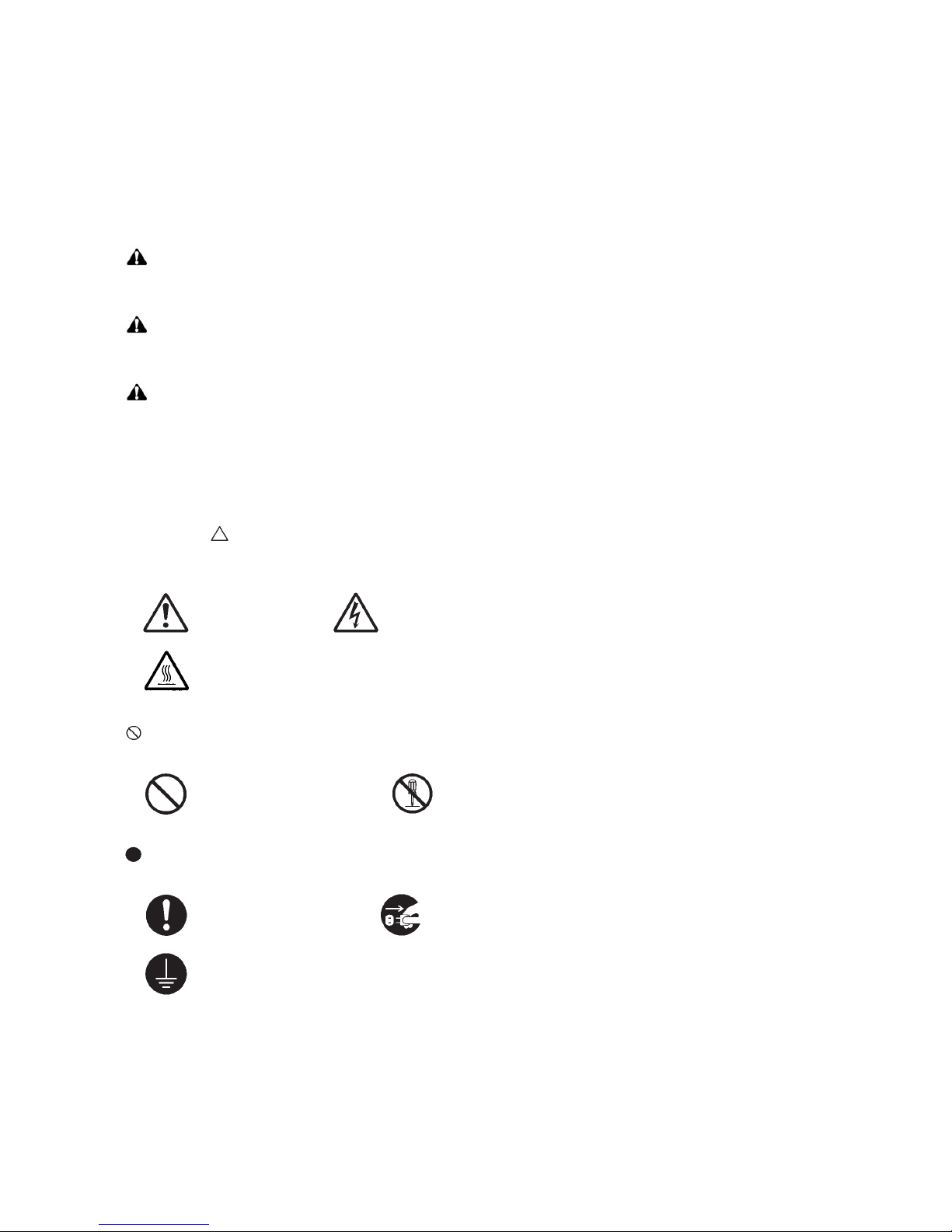
The triangle ( ) symbol indicates a warning including danger and caution. The specific point of attention is
shown inside the symbol.
General warning. Warning of risk of electric shock.
Warning of high temperature.
indicates a prohibited action. The specific prohibition is shown inside the symbol.
General prohibited action. Disassembly prohibited.
indicates that action is required. The specific action required is shown inside the symbol.
General action required. Remove the power plug from the wall outlet.
Always ground the copier.

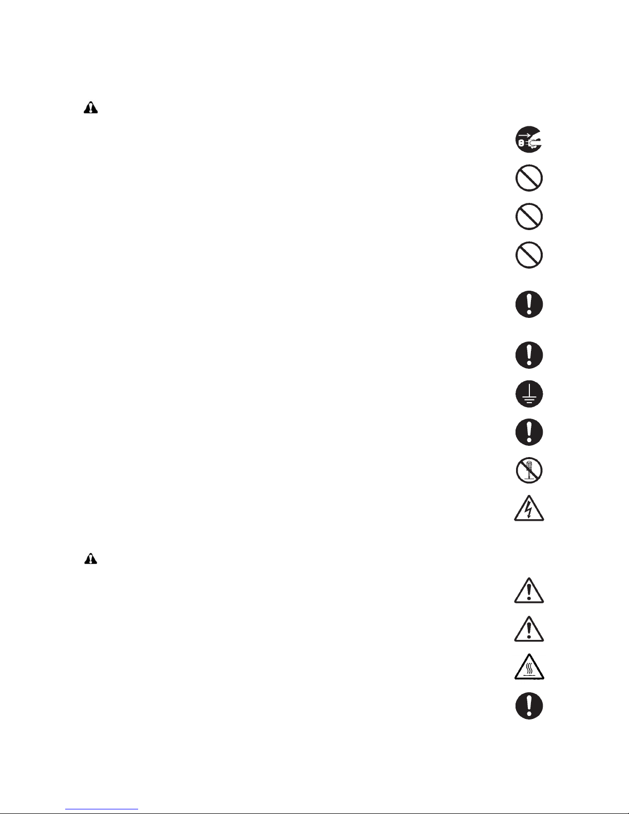
1. Installation Precautions
WARNING
• Do not use a power supply with a voltage other than that specified. Avoid multiple connections to
one outlet: they may cause fire or electric shock. When using an extension cable, always check that
it is adequate for the rated current. .....................................................................................................
• Connect the ground wire to a suitable grounding point. Not grounding the copier may cause fire or
electric shock. Connecting the earth wire to an object not approved for the purpose may cause
explosion or electric shock. Never connect the ground cable to any of the following: gas pipes, lightning rods, ground cables for telephone lines and water pipes or faucets not approved by the proper
authorities. ..........................................................................................................................................
CAUTION:
• Do not place the copier on an infirm or angled surface: the copier may tip over, causing injury. .........
• Do not install the copier in a humid or dusty place. This may cause fire or electric shock. .................
• Do not install the copier near a radiator, heater, other heat source or near flammable material. This
may cause fire. ...................................................................................................................................
• Allow sufficient space around the copier to allow the ventilation grills to keep the machine as cool
as possible. Insufficient ventilation may cause heat buildup and poor copying performance. ............
• Always handle the machine by the correct locations when moving it. .................................................
• Always use anti-toppling and locking devices on copiers so equipped. Failure to do this may cause
the copier to move unexpectedly or topple, leading to injury. ..............................................................
• Avoid inhaling toner or developer excessively. Protect the eyes. If toner or developer is accidentally
ingested, drink a lot of water to dilute it in the stomach and obtain medical attention immediately.
If it gets into the eyes, rinse immediately with copious amounts of water and obtain medical atten-
tion. .....................................................................................................................................................
• Advice customers that they must always follow the safety warnings and precautions in the copier’s
instruction handbook. .........................................................................................................................
2. Precautions for Maintenance
WARNING
• Always remove the power plug from the wall outlet before starting machine disassembly. ................
• Always follow the procedures for maintenance described in the service manual and other related
brochures. ..........................................................................................................................................
• Under no circumstances attempt to bypass or disable safety features including safety mechanisms
and protective circuits. ........................................................................................................................
• Always use parts having the correct specifications. ............................................................................
• Always use the thermostat or thermal fuse specified in the service manual or other related brochure
when replacing them. Using a piece of wire, for example, could lead to fire or other serious acci-
dent. ...................................................................................................................................................
• When the service manual or other serious brochure specifies a distance or gap for installation of a
part, always use the correct scale and measure carefully. ..................................................................
• Always check that the copier is correctly connected to an outlet with a ground connection. ...............
• Check that the power cable covering is free of damage. Check that the power plug is dust-free. If it
is dirty, clean it to remove the risk of fire or electric shock. .................................................................
• Never attempt to disassemble the optical unit in machines using lasers. Leaking laser light may
damage eyesight. ...............................................................................................................................
• Handle the charger sections with care. They are charged to high potentials and may cause electric
shock if handled improperly. ...............................................................................................................
CAUTION
• Wear safe clothing. If wearing loose clothing or accessories such as ties, make sure they are safely
secured so they will not be caught in rotating sections. ......................................................................
• Use utmost caution when working on a powered machine. Keep away from chains and belts. ..........
• Handle the fixing section with care to avoid burns as it can be extremely hot. ..................................
• Check that the fixing unit thermistor, heat and press rollers are clean. Dirt on them can cause
abnormally high temperatures. ...........................................................................................................
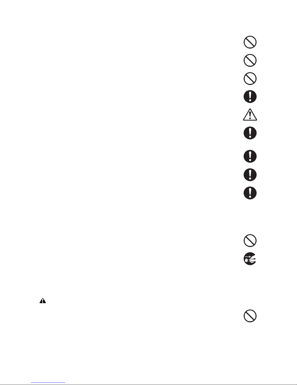
• Do not remove the ozone filter, if any, from the copier except for routine replacement. ......................
• Do not pull on the AC power cord or connector wires on high-voltage components when removing
them; always hold the plug itself. ........................................................................................................
• Do not route the power cable where it may be stood on or trapped. If necessary, protect it with a
cable cover or other appropriate item. ................................................................................................
• Treat the ends of the wire carefully when installing a new charger wire to avoid electric leaks. ..........
• Remove toner completely from electronic components. .....................................................................
• Run wire harnesses carefully so that wires will not be trapped or damaged. ......................................
• After maintenance, always check that all the parts, screws, connectors and wires that were
removed, have been refitted correctly. Special attention should be paid to any forgotten connector,
trapped wire and missing screws. .......................................................................................................
• Check that all the caution labels that should be present on the machine according to the instruction
handbook are clean and not peeling. Replace with new ones if necessary. .......................................
• Handle greases and solvents with care by following the instructions below: ......................................
· Use only a small amount of solvent at a time, being careful not to spill. Wipe spills off completely.
· Ventilate the room well while using grease or solvents.
· Allow applied solvents to evaporate completely before refitting the covers or turning the power
switch on.
· Always wash hands afterwards.
• Never dispose of toner or toner bottles in fire. Toner may cause sparks when exposed directly to
fire in a furnace, etc. ...........................................................................................................................
• Should smoke be seen coming from the copier, remove the power plug from the wall outlet immedi-
ately. ...................................................................................................................................................
3. Miscellaneous
WARNING
• Never attempt to heat the drum or expose it to any organic solvents such as alcohol, other than the
specified refiner; it may generate toxic gas. ........................................................................................

This page is intentionally left blank.

3NC/3NB/3NK
CONTENTS
1-1 Specifications
1-1-1 Specifications ........................................................................................................................1-1-1
1-1-2 Parts names ..........................................................................................................................1-1-2
(1) Document Finisher ...........................................................................................................1-1-2
(2) Bridge unit ........ ... ... .... .......................................... ... ... ... .... ..............................................1-1-3
1-1-3 Machine cross section...........................................................................................................1-1-4
1-2 Installation
1-2-1 Installation environment.........................................................................................................1-2-1
1-2-2 Unpacking..............................................................................................................................1-2-2
(1) Unpacking.........................................................................................................................1-2-2
(2) Removing the tapes and pads..........................................................................................1-2-4
1-3 Maintenance Mode
1-3-1 Maintenance mode................................................................................................................1-3-1
(1) Executing a maintenance item .......... ... .... ... ... ... .... ... ... ....... ... ... ... ... .... ... ... ... .... ... ... ... ... .... .1-3-1
(2) Maintenance modes item list............................................................................................1-3-2
(3) Contents of the maintenance mode items......................................................................1-3-10
1-4 Troubleshooting
1-4-1 Paper misfeed detection............ .... ... ... .......................................... ... ... .... ..............................1-4-1
(1) Paper misfeed indication..................................................................................................1-4-1
(2) Paper misfeed detection condition ...................................................................................1-4-2
1-4-2 Self-diagnostic function ....................................... ... .......................................... .... ... ... ... ......1-4-27
(1) Self-diagnostic function ..................................................................................................1-4-27
(2) Self diagnostic codes......................................................................................................1-4-28
1-4-3 Image formation problems................ ... ... ... .... ... ... .......................................... ... .... ... ............1-4-88
(1) No image appears (entirely white)..................................................................................1-4-89
(2) No image appears (entirely black)..................................................................................1-4-90
(3) Image is too light. ...........................................................................................................1-4-91
(4) The background is colored.............................................................................................1-4-91
(5) White streaks are printed vertically.................................................................................1-4-92
(6) Black streaks are printed vertically.................................................................................1-4-92
(7) Streaks are printed horizontally......................................................................................1-4-92
(8) One side of the print image is darker than the other. .....................................................1-4-93
(9) Spots are printed............................................................................................................1-4-93
(10) Image is blurred..............................................................................................................1-4-93
(11) The leading edge of the image is consistently misaligned with the original. ............ ... ...1-4-94
(12) The leading edge of the image is sporadically misaligned with the original...................1-4-94
(13) Paper is wrinkled............................................................................................................1-4-94
(14) Offset occurs. .................................................................................................................1-4-95
(15) Part of image is missing. ................................................................................................1-4-95
(16) Fusing is loose................................................................................................................1-4-95
(17) Image is out of focus. .....................................................................................................1-4-96
(18) Image center does not align with the original center. .................. ... .... ... ... ......................1-4-96
1-4-4 Electric problems.................................................................................................................1-4-97
1-4-5 Mechanical problems. ... .....................................................................................................1-4-105
1-4-6 Send error code.................................................................................................................1-4-107
(1) Scan to SMB error codes .............................................................................................1-4-107
(2) Scan to FTP error codes ..............................................................................................1-4-108

3NC/3NB/3NK
(3) Scan to E-mail error codes...........................................................................................1-4-109
1-4-7 Error codes........................................................................................................................1-4-110
(1) Error code....................................... .......................................... ... ... .... ..........................1-4-110
(2) Table of general classification......................................................................................1-4-111
(2-1) U004XX error code table: Interrupted phase B...................................................1-4-113
(2-2) U006XX error code table: Problems with the unit ...............................................1-4-113
(2-3) U008XX error code table: Page transmission error............ ... .... ... ... ... .... ... ... ... ... .1-4-113
(2-4) U009XX error code table: Page reception error..................................................1-4-113
(2-5) U010XX error code table: G3 transmission.........................................................1-4-114
(2-6) U011XX error code table: G3 reception ..............................................................1-4-115
(2-7) U017XX error code table: V.34 transmission ......................................................1-4-116
(2-8) U018XX error code table: V.34 reception............................................................1-4-116
1-5 Assembly and disassembly
1-5-1 Precautions for assembly and disassembly...........................................................................1-5-1
(1) Precautions.......................................................................................................................1-5-1
1-5-2 Document finisher section .....................................................................................................1-5-2
(1) Detaching and refitting the front cover and rear cover .....................................................1-5-2
(2) Detaching and refitting the PF main PWB........................................................................1-5-3
(3) Detaching and refitting the Staple unit..............................................................................1-5-4
1-6 Requirements on PWB Replacement
1-6-1 Remarks on finisher PWB replacement.................................................................................1-6-1
2-1 Mechanical Construction
2-1-1 Bridge unit section......................................................................................... ... .... ... ..............2-1-1
2-1-2 Prosessing section ................................................................................................................2-1-3
(1) Bundle discharge operation..............................................................................................2-1-5
2-1-3 Eject tray section ...................................................................................................................2-1-6
2-1-4 Punch unit(Option).................................................................................................................2-1-8
2-2 Electrical Parts Layout
2-2-1 Electrical parts layout ............................................................................................................2-2-1
(1) PWBs................................................................................................................................2-2-1
(2) Switches and sensors.......................................................................................................2-2-2
(3) Motors...............................................................................................................................2-2-3
(4) Bridge section.................................... .......................................... ... .... ... ...........................2-2-4
(5) Punch unit(Option).................... ... ... ... ... .... ... .......................................... ... ... .... .................2-2-5
2-3 Operation of the PWBs
2-3-1 DF main PWB........................................................................................................................2-3-1
2-3-2 Bridge PWB................................................... ... .......................................... ... ... .... .................2-3-6
2-3-3 Punch unit PWB ....................................................................................................................2-3-8
2-4 Appendixes
2-4-1 Appendixes............................................................................................................................2-4-1
(1) Wiring diagram ................................................................................................................2-4-1
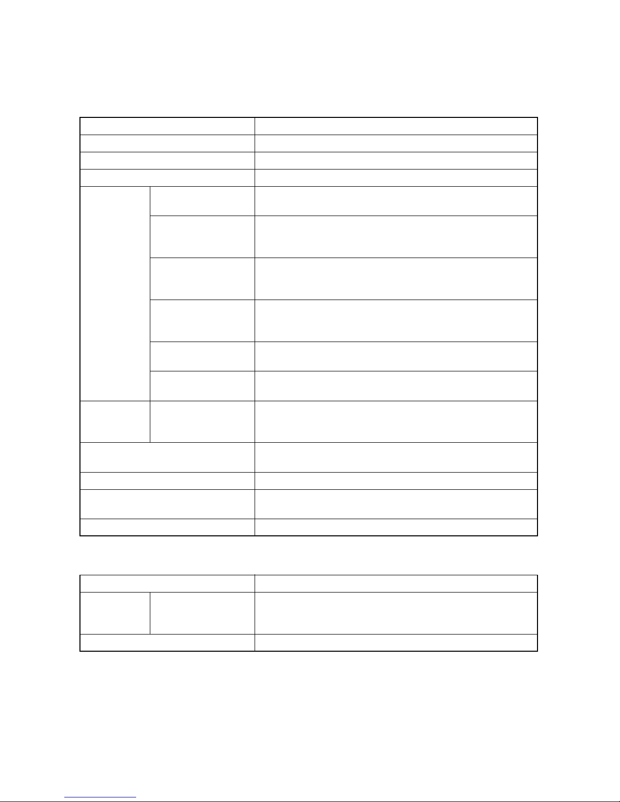
1-1 Specifications
1-1-1 Specifications
Item Specifications
Type Floor model
Number of trays Two tray
Paper weight 45 to 300 g/m
When not stapling
When stapling 2 or 4
sheets
Tray capacity
Main Try
(Try A)
Tray capacity
Sub Try
(Try B)
Paper weight 90 g/m
Dimensions (W × D × H)
When stapling 5 or10
sheets
When stapling 11 or
20 sheets
When stapling 21 or
30 sheets
When stapling 21 or
50 sheets
Stapling capacity
2
or less
Power source Electrically connected to the machine
Weight Approx. 26.5 kg/Approx. 58.42 lb
3NC/3NB/3NK
2
A3, B4, Ledger, Legal, Oficio II, 12×18", 8K: 500 sheets
A4, A4R, B5, Letter, LetterR, 16K: 1000 sheets
A3, B4, Ledger, Legal, 8K: 220 sheets(55-110 sets)
A4R, LetterR: 350 sheets(85-175 sets)
A4, B5,Letter, 16K:350 sheets(85-175 sets)
A3, B4, Ledger, Legal, 8K: 250 sheets(20-50 sets)
A4R, LetterR: 350 sheets(35-70 sets)
A4, B5,Letter, 16K:350 sheets(35-70 sets)
A3, B4, Ledger, Legal, 8K: 300 sheets(15-30 sets)
A4R, LetterR: 400 sheets(20-40 sets)
A4, B5,Letter, 16K: 400 sheets(20-40 sets)
A3, B4, Ledger, Legal, 8K: 500 sheets(16-25 sets)
A4, A4R, B5, Letter, LetterR, 16K: 1000 sheets(20-50 sets)
A4, A4R, B5, Letter, LetterR, 16K: 100 sheets
A3, B4, Ledger, Legal, 12×18", 8K: 30 sheets
A4, A4R, B5, Letter, LetterR, 16K: 50 sheets
666 ×618.5 ×1013.5 mm
26 7/32 × 24 11 × 32 × 39 57/64”
Item Specifications
Tray capacity
Main Try
When not stapling
(Try A)
Paper weight 45 to 300 g/m
NOTE: These specifications are subject to change without notice.
A3, B4, Ledger, Legal,Statement R, Folio, A4, A4R, B5, B5R, Letter, LetterR,12×18",8K,16K,16KR
2
1-1-1
1-1-2 Parts names
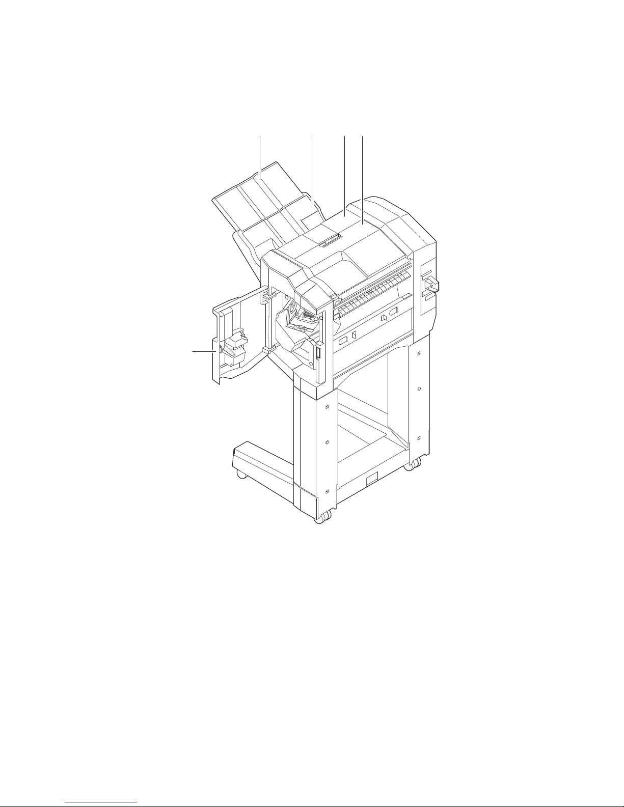
1. DF Main tray(tray A)
2. DF tray extension
3. DF top cover
4. DF Sub tray(tray B)
5. DF Front cover
(1) Document Finisher
3NC/3NB/3NK
213
4
5
Figure 1-1-1
1-1-2
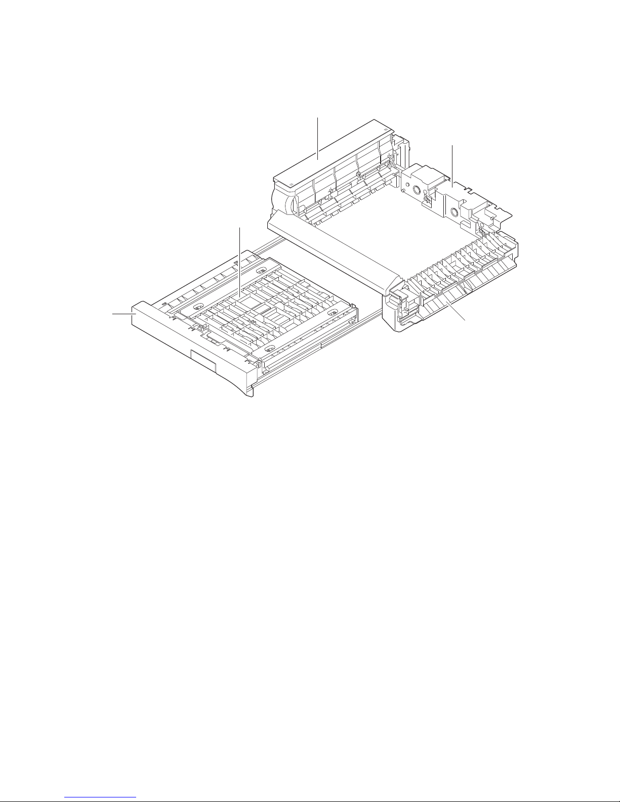
(2) Bridge unit
1. Bridge eject cover
2. Bridge conveying unit
3. Bridge conveying cover
4. Bridge drive unit
5. Bridge entry unit
3NC/3NB/3NK
1
4
3
2
Figure 1-1-2
5
1-1-3
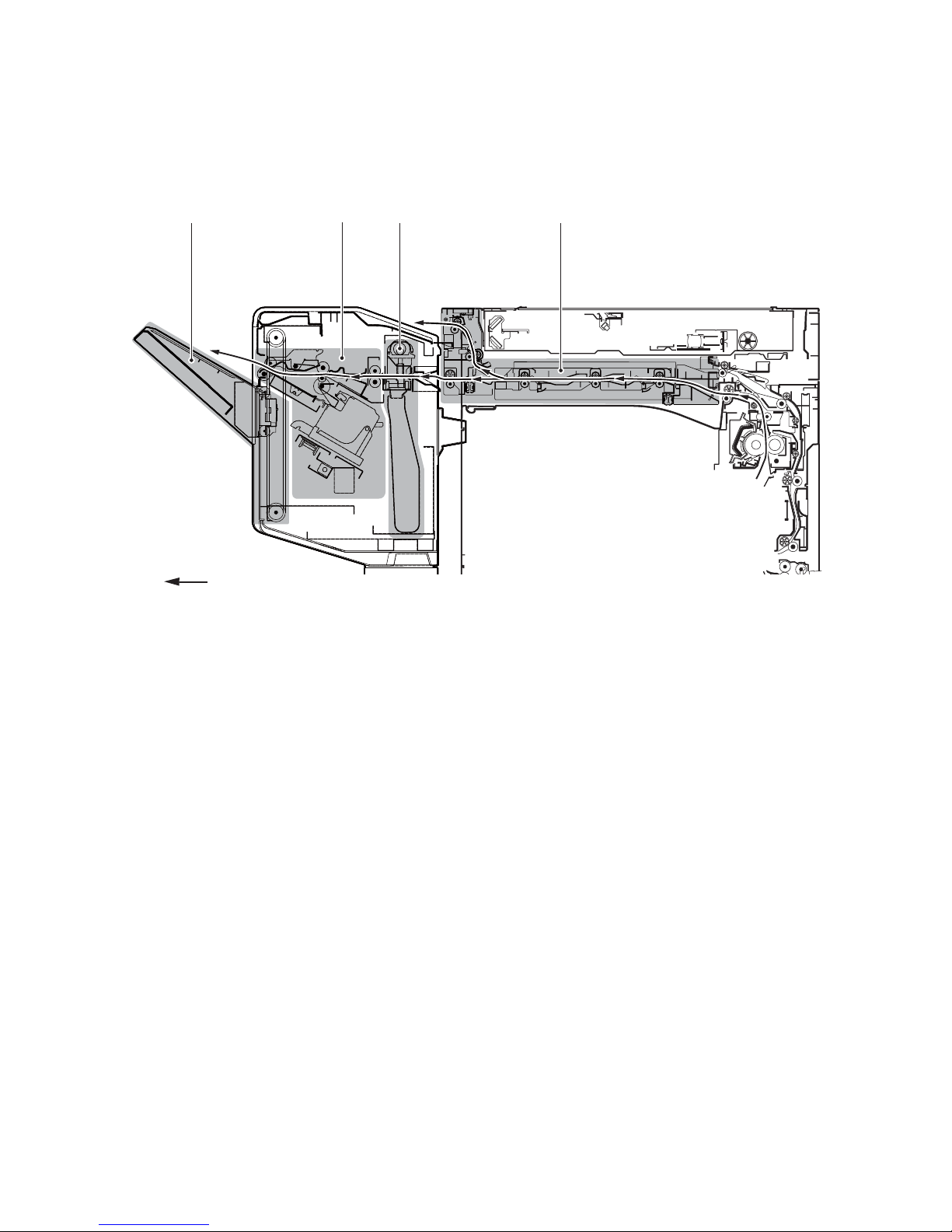
1-1-3 Machine cross section
1. DF processing section
2. Eject tray section
3. Bridge unit section
4. Punch unit (Option)
3NC/3NB/3NK
2 1
Paper path
4
3
Figure 1-1-3
1-1-4

3NC/3NB/3NK
1-2 Installation
1-2-1 Installation environment
Installation location (Be based on the machine establishment place.)
Avoid direct sunlight or bright lighting. Ensure that the photoconductor will not be exposed to direct sunlight or
other strong light when removing paper jams.
Avoid locations subject to high temperature and high humidity or low temperature and low humidity; an abrupt
change in the environmental temperature; and cool or hot, direct air.
Avoid places subject to dust and vibrations.
Choose a surface capable of supporting the weight of the machine.
Place the machine on a level surface (maximum allowance inclination: 1°).
Avoid air-borne substances that may adversely affect the machine or degrade the photoconductor, such as
mercury, acidic of alkaline vapors, inorganic gasses, NOx, SOx gases and chlorine-based organic solvents.
Select a well-ventilated location.
1-2-1
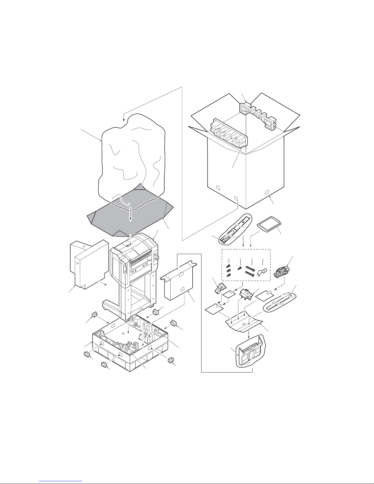
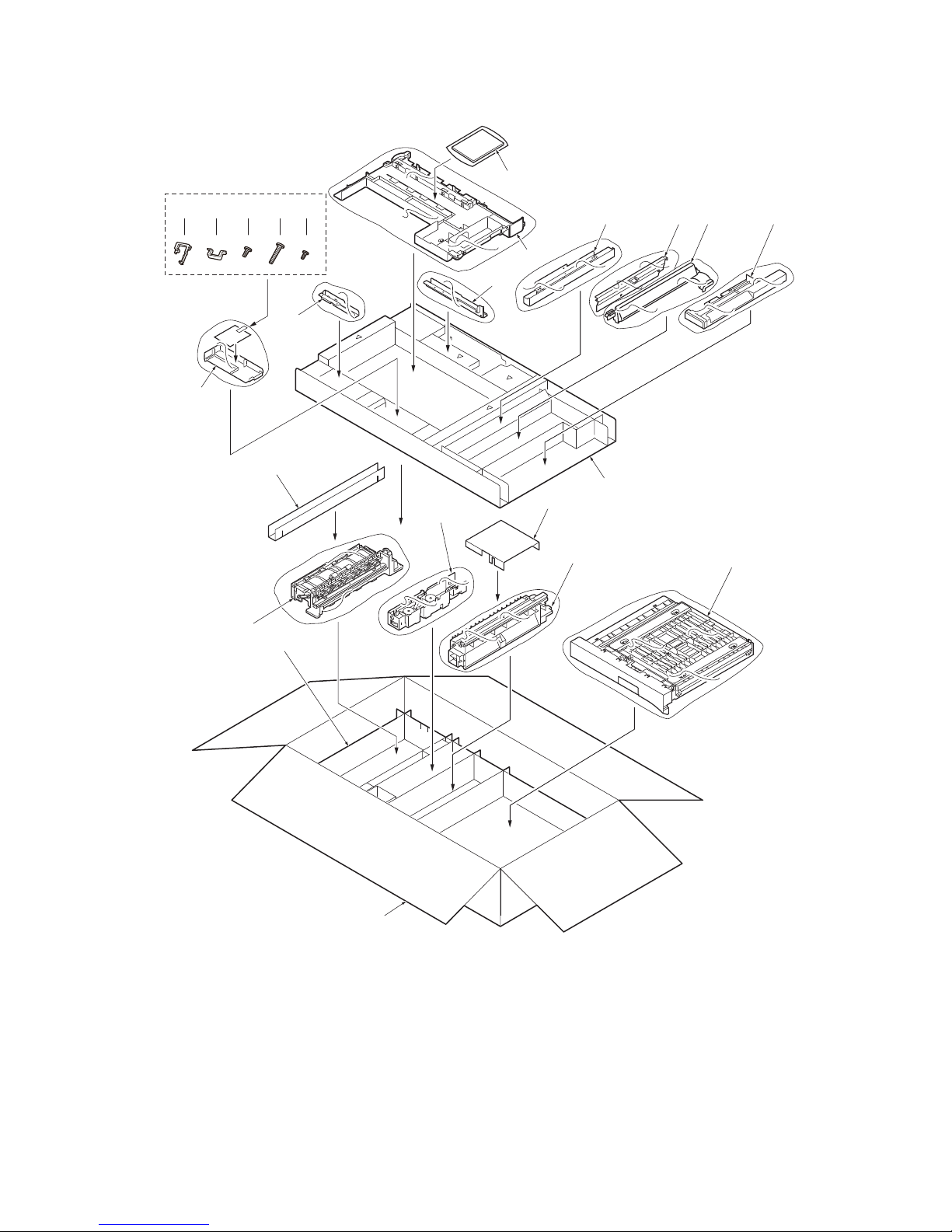
1-2-2 Unpacking
1. Skid
2. Bottom right pad
3. Bottom left pad
4. Document Finisher
5. Spacer A
6. Plastic sheet
7. Plastic sheet
8. Outer case
9. Upper right pad
10. Upper left pad
11. Spacer B
12. Finisher tray
13. Spacer C
14. Lower earth plate
15. Wire guide
16. Staple cartridge
17. Eject guide
18. M4 x 8 screw
19. M4 x 10 screw(black)
20. M4 x 30 screw
21. Upper earth plate
22. Connecting plate
23. Installation guide,etc.
24. Hinge joints
(1) Unpacking
Document Finisher
7
3NC/3NB/3NK
10
9
8
4
6
22
18 19 20 21
23
16
14
15
17
5
24
24
1
11
24
3
12
13
24
24
2
24
Figure 1-2-1
1-2-2
Bridge unit
1. Outer case
2. Bottom spacer
3. Bridge conveying unit
4. Bridge entry unit
5. Bridge drive unit
6. Bridge eject unit
7. Spacer A
8. Spacer B
9. Top spacer
10. Left connevtion cover
11. Upper front cover
12. Left scanner cover
13. Lower connevtion
cover
14. Left cover
15. Front left stay
16. Rear left stay
17. Upper left cover
18. Edging
19. Wire stopper
20. M4 x 8 screw
21. M4 x 20 screw
22. P Tite screw M3 x 8
23. Installation guide,etc.
3NC/3NB/3NK
23
18 19 20 21 22
16
17
7
6
2
13 12 11 10
14
15
8
9
5
4
3
See the Installation Guide for installation.
1
Figure 1-2-2
1-2-3
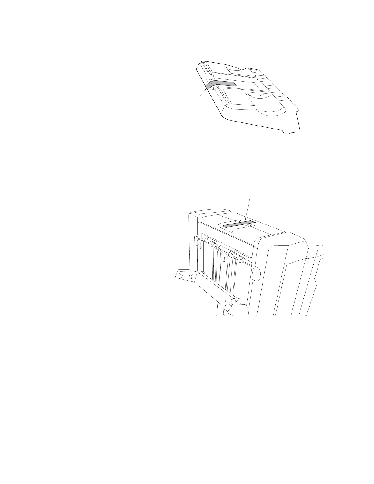
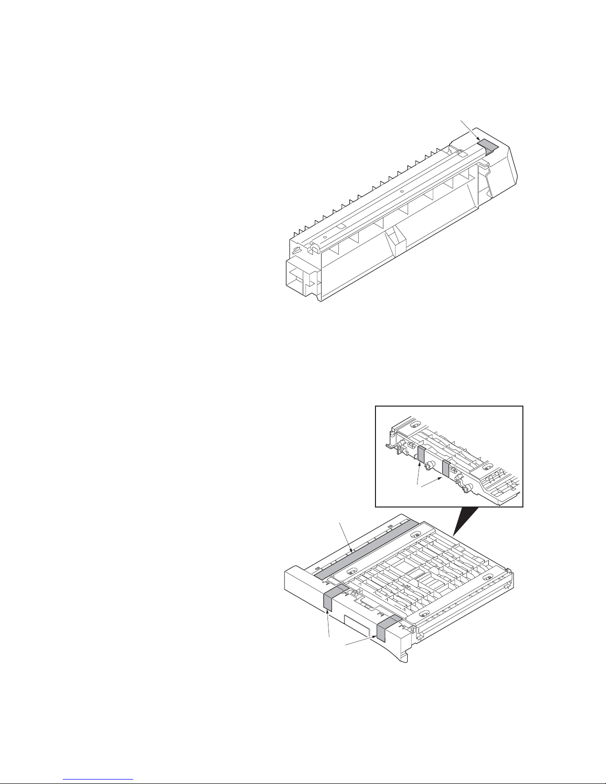
(2) Removing the tapes and pads
1. Remove tape from the finisher try.
2. Remove tape from the document
finisher.
3NC/3NB/3NK
Ta pe
Figure 1-2-3
Ta pe
Figure 1-2-4
1-2-4
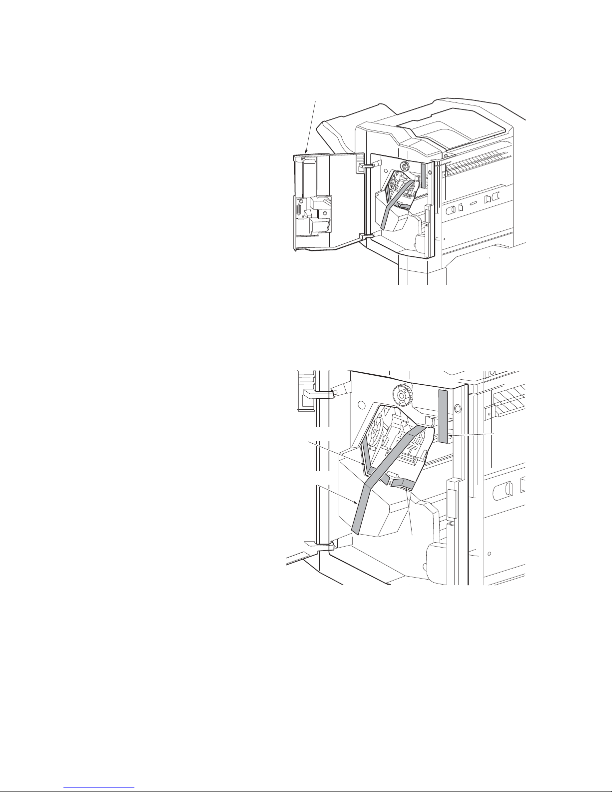
3. Open the DF front cover.
3NC/3NB/3NK
DF front cover
Figure 1-2-5
4. Remove four tapes.
Ta pe
Ta pe
Ta pe
Ta pe
Figure 1-2-6
1-2-5
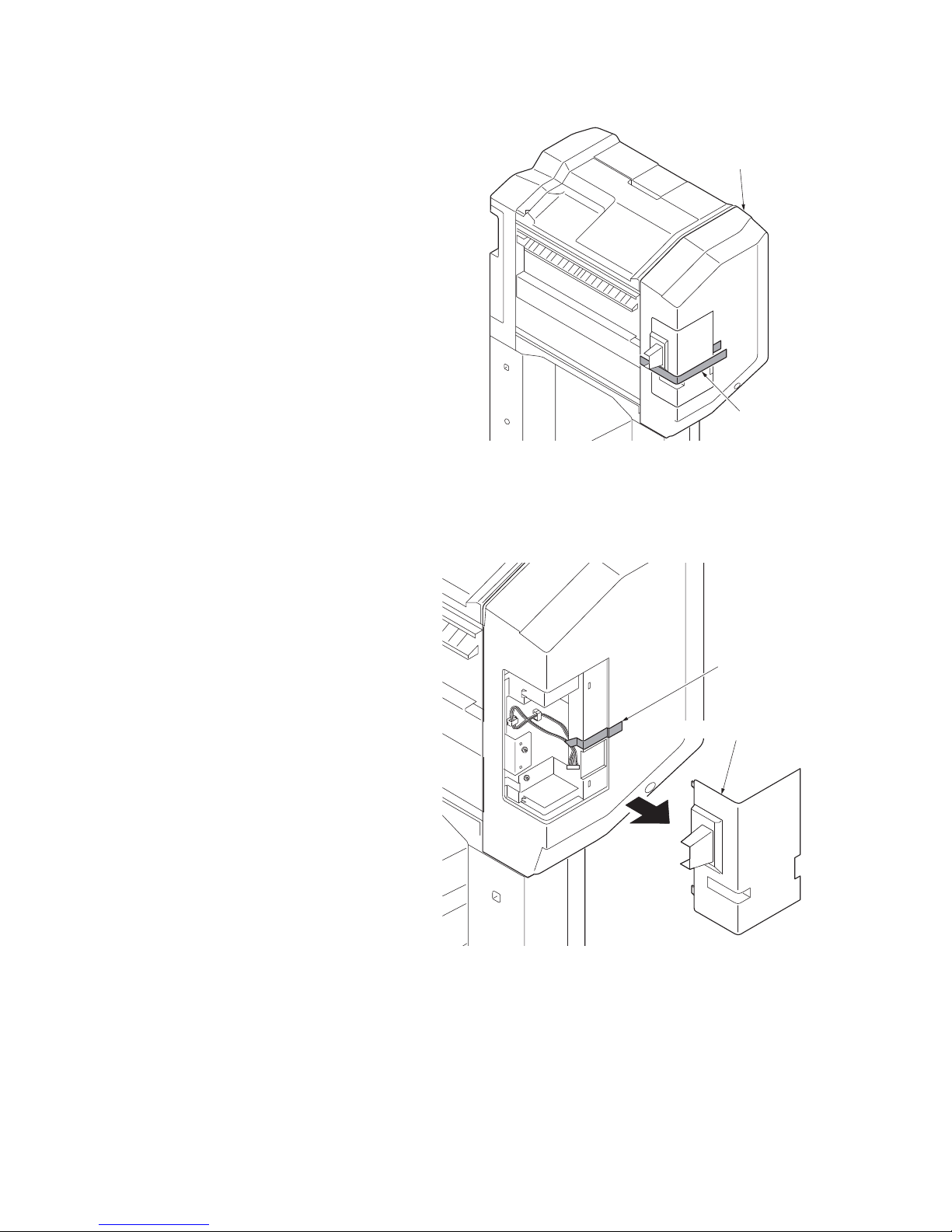
5. Remove tape from the DF rear cover.
3NC/3NB/3NK
DF rear cover
Tape
Figure 1-2-7
6. Remove the lid rear cover and then
remove tape .
Tape
Lid rear cover
Figure 1-2-8
1-2-6
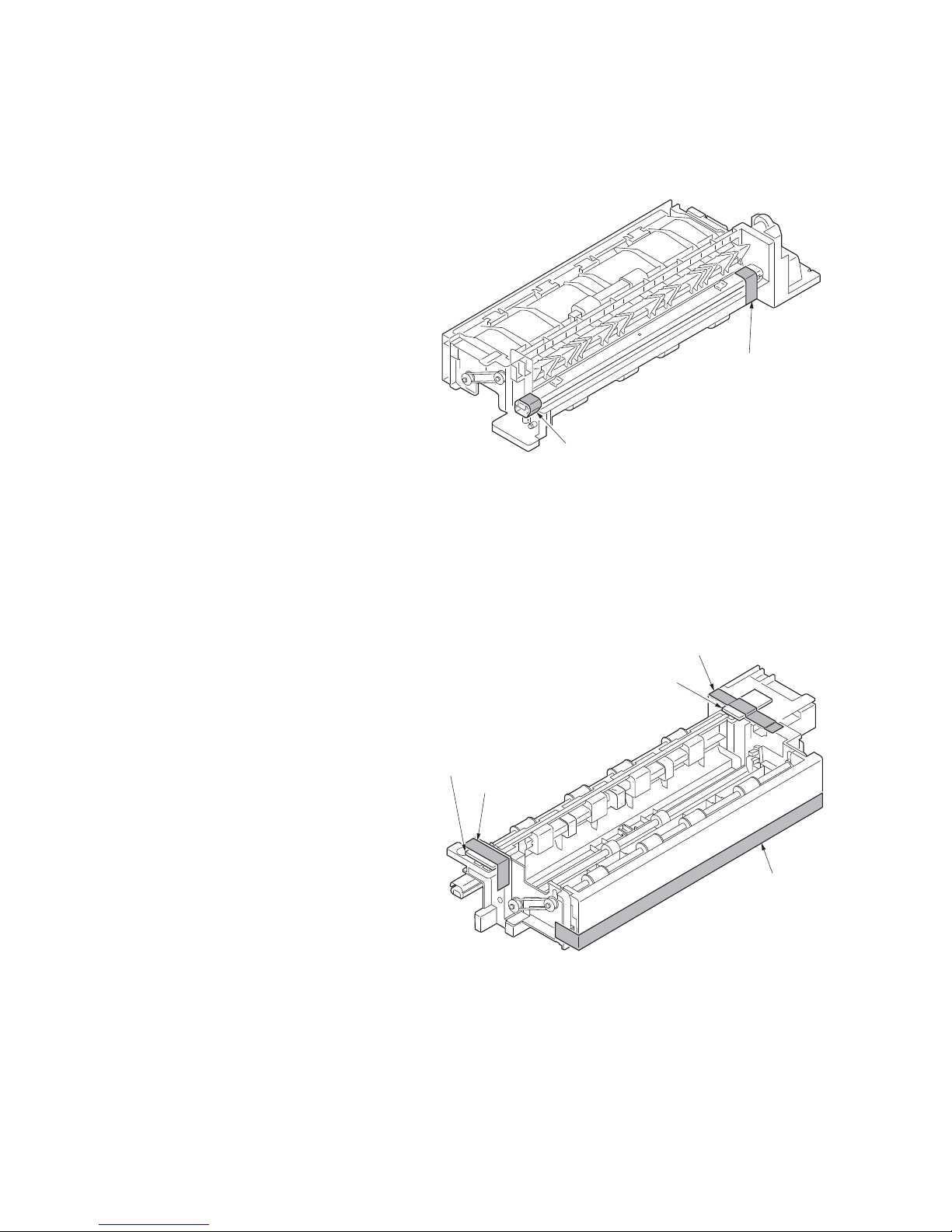
7. Remove tape from the bridge entry unit.
3NC/3NB/3NK
Ta pe
8. Remove five tapes from bridge conveying unit.
Figure 1-2-9
Ta pe s
Ta pe
Ta pe s
Figure 1-2-10
1-2-7
9. Remove two tapes from the bridge eject
unit.
3NC/3NB/3NK
Ta pe
Ta pe
10. Remove three tapes and two pads.
Figure 1-2-11
Ta pe
Pad
Pad
Ta pe
Tape
Figure 1-2-12
1-2-8
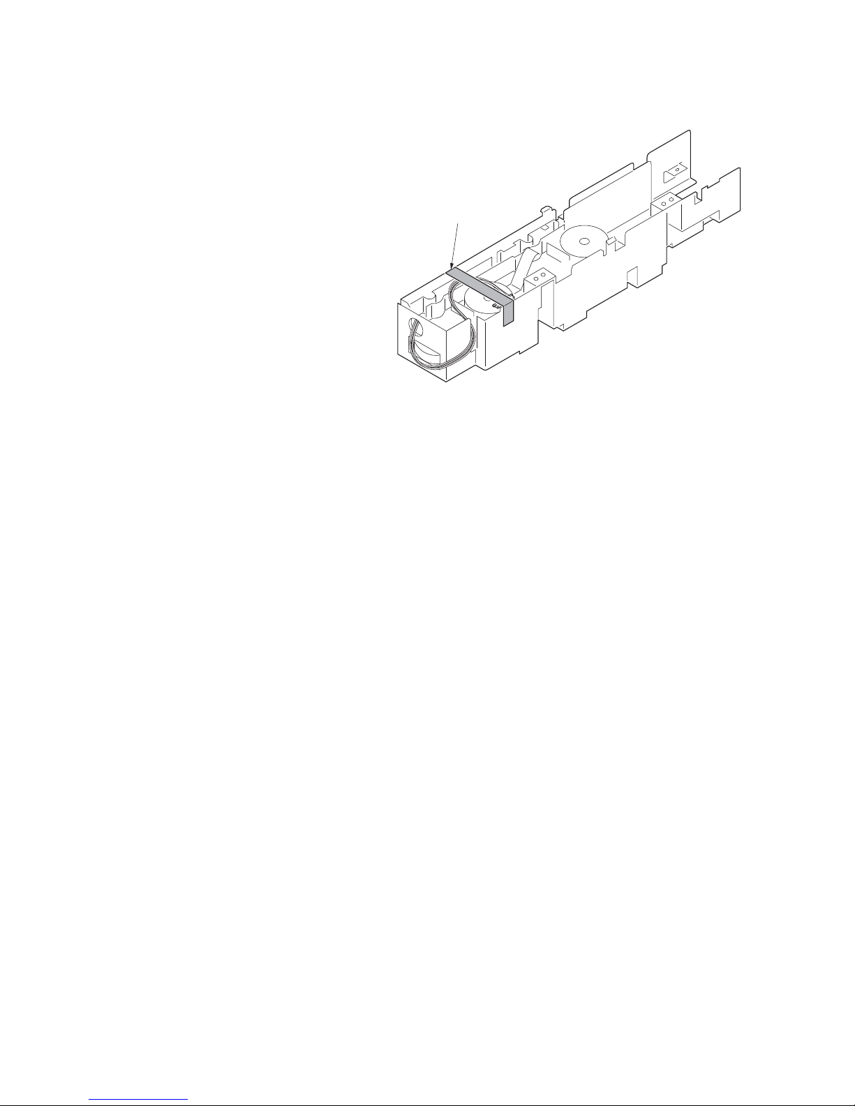
11. Remove tape from the bridge drive unit.
3NC/3NB/3NK
Ta pe
Figure 1-2-13
1-2-9

3NC/3NB/3NK
This page is intentionally left blank.
1-2-10
3NC/3NB/3NK
1-3 Maintenance Mode
1-3-1 Maintenance mode
The machine is equipped with a maintenance function which can be used to maintain and service the
machine.
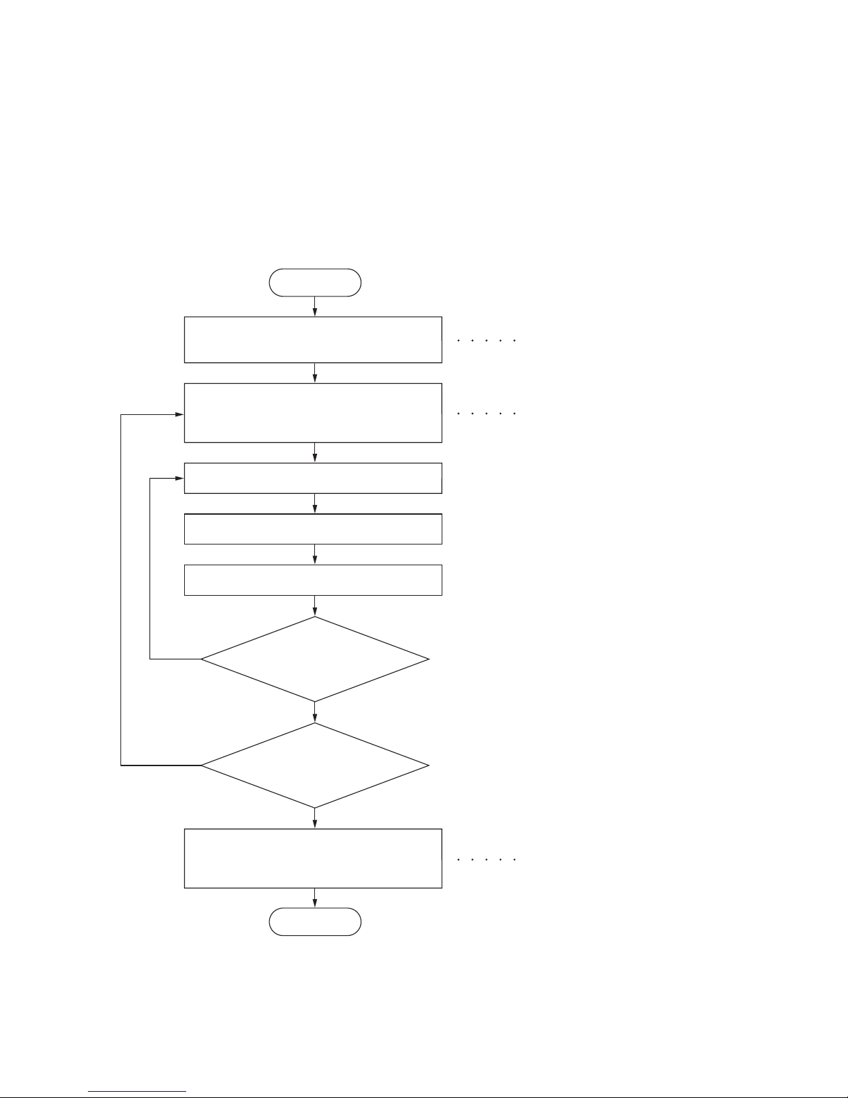
(1) Executing a maintenance item
Start
Enter “10871087” using
the numeric keys.
Enter the maintenance item
number using the cursor
or numeric keys.
Press the start key.
The selected maintenance item is run.
Press the stop key.
Yes
Repeat the same
maintenance item?
No
up/down
keys
Maintenance mode is entered.
The maintenance item is selected.
Yes
Run another maintenance
Enter 001 using the cursor
up/down keys or numeric keys
and press the start key.
item?
No
Maintenance mode is exited.
End
1-3-1

(2) Maintenance modes item list
3NC/3NB/3NK
Section
General U019 Displaying the ROM version Others U905 Checking counts by optional devices -
Item
No.
Content of maintenance item Initial setting
1-3-2

Contents of the maintenance mode items
Display Description
Main Main ROM
MMI Operation ROM
Browser Browser ROM
Engine Engine ROM
Engine Boot Engine booting
Scanner Scanner ROM
Scanner Boot Scanner booting
RFID RFID ROM
IH CPU IH CPU ROM
IH CPU Boot IH CPU booting
Motor CPU Motor CPU ROM
Motor CPU Boot Motor CPU booting
Dictionary Option Language Optional language ROM
PDF1.7 Resource PDF1.7 resource ROM
Solution Framework Framework ROM
FMU FMU ROM
Weekly Timer Weekly Timer ROM
Color Table1(Copy) Color table 1 (copy) ROM
Color Table2(Copy) Color table 2 (copy) ROM
Color Table1(Prn) Color table 1 (printer) ROM
Color Table2(Prn) Color table 2 (printer) ROM
DP Document processor ROM
DP Boot Document pr ocessor booting
PF1 Paper feeder / Large capacity feeder ROM
PF1 Boot Paper feeder / Large capacity feeder booting
Side PF SMT paper feeder /Side feeder ROM
Item No. Description
U019 Displaying the ROM version
Description
Displays the part number of the ROM fitted to each PWB.
Purpose
To check the part number or to decide, if the newest version of ROM is installed.
Method
1. Press the start key. The ROM version are displayed.
2. Change the screen using the cursor up/down keys.
3NC/3NB/3NK
1-3-3
Item No. Description
Display Description
Side PF Boot SMT paper feeder /Side feeder booting
PF2 Sid e paper feeder / Side large capacity feeder ROM
PF2 Boot Side paper feeder / Side large capacity feeder booting
DF 1000-sheet finisher / 4000-sheet finisher ROM
DF Boot 1000-sheet finisher / 4000-sheet finisher booting
PH Punch unit ROM
PH Boot Punch unit booting
MT Mailbox ROM
MT Boot Mailbox booting
BF Center-folding unit ROM
BF Boot Center-folding unit booting
Fax APL1 Fax APL 1
Fax Boot1 Fax booting 1
Fax IPL1 Fax IPL 1
Fax APL2 Fax APL 2 (dual Fax)
Fax Boot2 Fax booting 2 (dual Fax)
Fax IPL2 Fax IPL 2 (dual Fax)
U019
3NC/3NB/3NK
Completion
Press the stop key. The screen for selecting a maintenance item No. is displayed.
1-3-4
 Loading...