

Page 1
Q
PREFACE
This Service Manual describes the
technical features and servicing
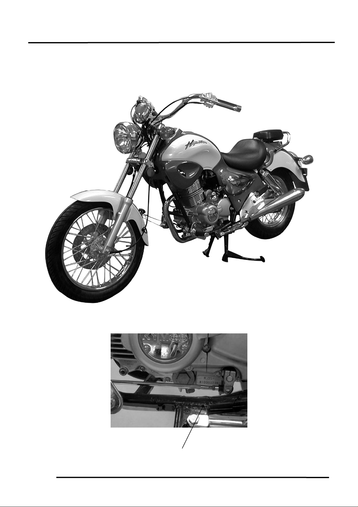
procedures for the KYMCOHipster125.
Section 1 contains the precautions for all
operations stated in this manual. Read
them carefully before starting any
operation.
Section 2 is the inspection/ adjustment
procedures, safety rules and service
information for each part, starting from
periodic maintenance.
Sections 3 and 4 state the servicing
procedures and cautions for the removal
and installation of lubrication and fuel
systems.
Sections 5 through 18 give instructions
for disassembly, assembly and inspection
of engine, chassis frame and electrical
equipment.
Most sections start with an assembly or
system illustration and troubleshooting
for the section. The subsequent pages
give detailed procedures for the section.
The information and contents included
in this manual may be different from
the motorcycle in case specifications
are changed.
KWANG YANG MOTOR CO., LTD.
OVERSEAS SALES DEPARTMENT
OVERSEAS SERVICE SECTION
HIPSTER125/150
TABLE OF CONTENTS
GENERAL INFORMATION 1
INSPECTION/ADJUSTMENT 2
LUBRICATION SYSTEM 3
FUEL SYSTEM 4
ENGINE
ENGINE REMOVAL/INSTALLATION 5
CYLINDER HEAD/VALVES 6
CYLINDER/PISTON 7
STARTER MOTOR/GENERATOR/
LEFT CRANKCASE COVER/STARTER
CLUTCH/CAMSHAFT
CLUTCH/GEAR SHIFT MECHANISM 9
CRANKCASE/CRANKSHAFT/TRANS-
MISSION SYSTEM/STARTER SPINDLE
FRONT WHEEL/SUSPENSION/
STEERING
CHASSIS
REAR WHEEL/BRAKE/SUSPENSION 12
HYDRAULIC BRAKE 13
REAR CARRIER/REAR FENDER/
EXHAUST MUFFLER
ELECTRICAL
E
IGNITION SYSTEM 15
UIPMENT
CHARGING SYSTEM 16
STARTING SYSTEM 17
LIGHTS/INSTRUMENTS/SWITCHES/
HORN
8
10
11
14
18
Page 2

1. GENERAL INFORMATION
HIPSTER 125/150
1
__________________________________________________________________________________
__________________________________________________________________________________
__________________________________________________________________________________
__________________________________________________________________________________
__________________________________________________________________________________
1
GENERAL INFORMATION
__________________________________________________________________________________
ENGINE SERIAL NUMBER---------------------------------------------- 1- 1
SPECIFICATIONS---------------------------------------------------------- 1- 2
SERVICE PRECAUTIONS------------------------------------------------ 1- 4
TORQUE VALUES --------------------------------------------------------- 1-12
SPECIAL TOOLS ----------------------------------------------------------- 1-13
LUBRICATION POINTS -------------------------------------------------- 1-14
CABLE & HARNESS ROUTING ---------------------------------------- 1-15
WIRING DIAGRAM-------------------------------------------------------- 1-17
TROUBLESHOOTING----------------------------------------------------- 1-18
1-0
Page 3
1. GENERAL INFORMATION
r
ENGINE SERIAL NUMBER
Location of Engine Serial Numbe
HIPSTER 125/150
1-1
Page 4
1. GENERAL INFORMATION
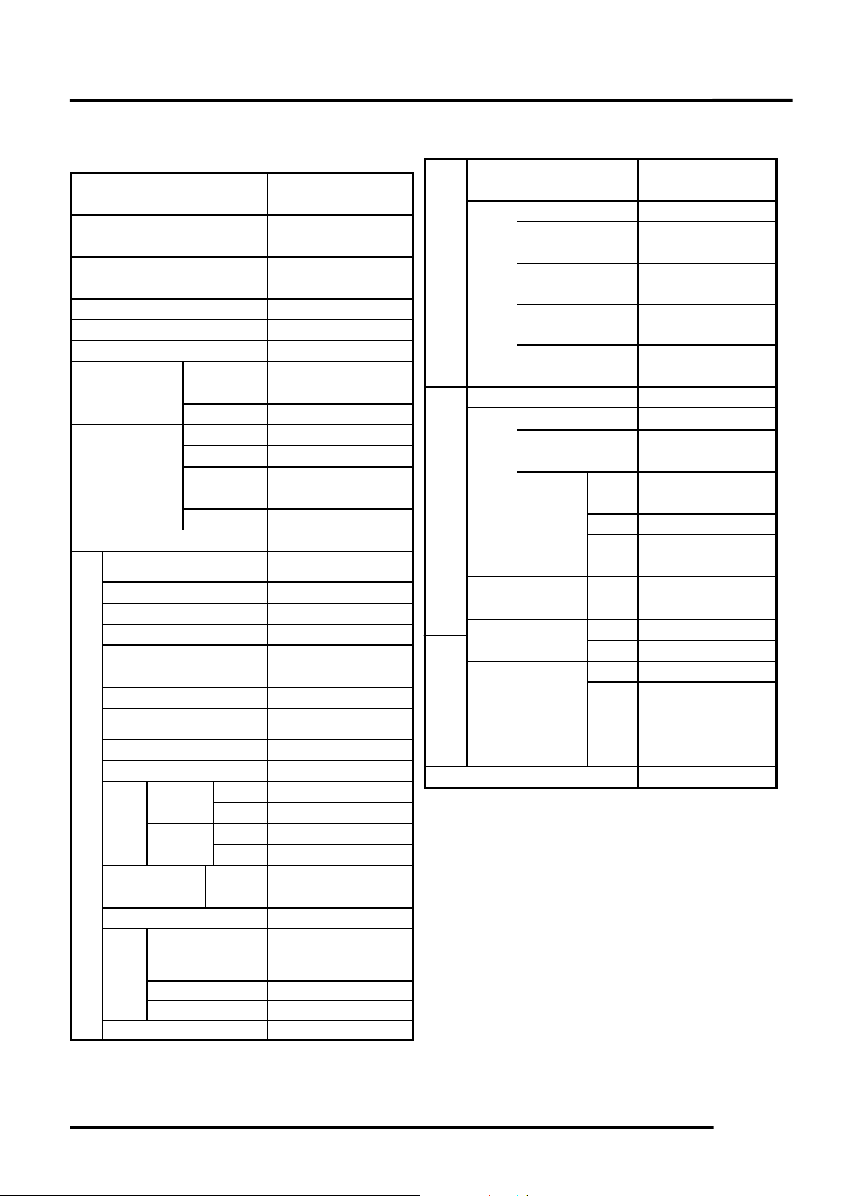
SPECIFICATIONS
Motorcycle name & Model No. RJ25AA
Motorcycle name HIPSTER125
Overall length (mm) 2250
Overall width (mm) 900
Overall height (mm) 1180
Wheel base (mm) 1475
Engine type 4 ∞
Displacement (cc) 124.1
Fuel type 92# nonleaded gasoline
Front wheel 59
Dry weight (kg)
Gross weight(kg)
Tires
Ground clearance (mm) 150
Starting system
Type OHC
Cylinder arrangement Single cylinder
Combustion chamber type Semi-sphere
Valve train OHC-2V
Bore x stroke (mm) 56.5 x 49.5
Compression ratio 9.4
Compression pressure
(kg/cm²)
Max. output (ps/rpm) 11.5/9000
Engine
Max. torque (Kg.m/rpm) 1.0/6000
Port
timing
Valve clearance
(cold)
Idle speed (rpm) 1600rpm
Lubrication
System
Oil filter type Wire gauze filter
Cooling Type Air cooling
Rear wheel 80
Total 139
Front wheel 67.5
Rear wheel 91
Total 158.5
Front wheel 3.00-18-4PR
Rear wheel 130/90-15-4PR
Starting motor &
kick starter
13
Intake
(mm)
Exhaust
(mm)
Lubrication type
Oil pump type Inner/outer rotor
Oil capacity 1.0L SAE#30
Open 5.5
Close 27.5
Open 4
Close 36
Intake 0.06mm
Exhaust 0.06mm
Forced pressure &
wet sump
Fuel System
Electrical
Equipment
Power Drive
System
Moving
Device
Damping
Device
Frame type Double cradle
SPECIFICATIONS
HIPSTER 125/150
Air cleaner type Paper element type
Fuel capacity 12.0 liter
Carburetor
Type CVK
Piston dia. (mm) φ26.5
Venturi dia.(mm) φ26
Throttle type Piston type
Ignition
System
Type CDI
Ignition timing 34.5° ±2/4000rpm
Spark plug NGK-DR8EA
Spark plug gap 0.60.7mm
Battery Capacity 12V6AH
Clutch Type Wet multi-disc clutch
Type Permanent gear meshing
Transmission Gear
Operating method Foot operated
Type International type
1st gear 2.846
Reduction
ratio
Tire pressure
(kg/cm²)(2 riders)
Turning angle
Brake system type
Shock absorber
type
2nd gear 2.063
3rd gear 1.4
4th gear 1.130
5th gear 0.923
Front 1.75
Rear 2.25
Left 43°
Right 43°
Front Disk brake
Rear Drum brake
Front Telescope
Rear Double swing
1-2
Page 5
1. GENERAL INFORMATION
y
HIPSTER 125/150
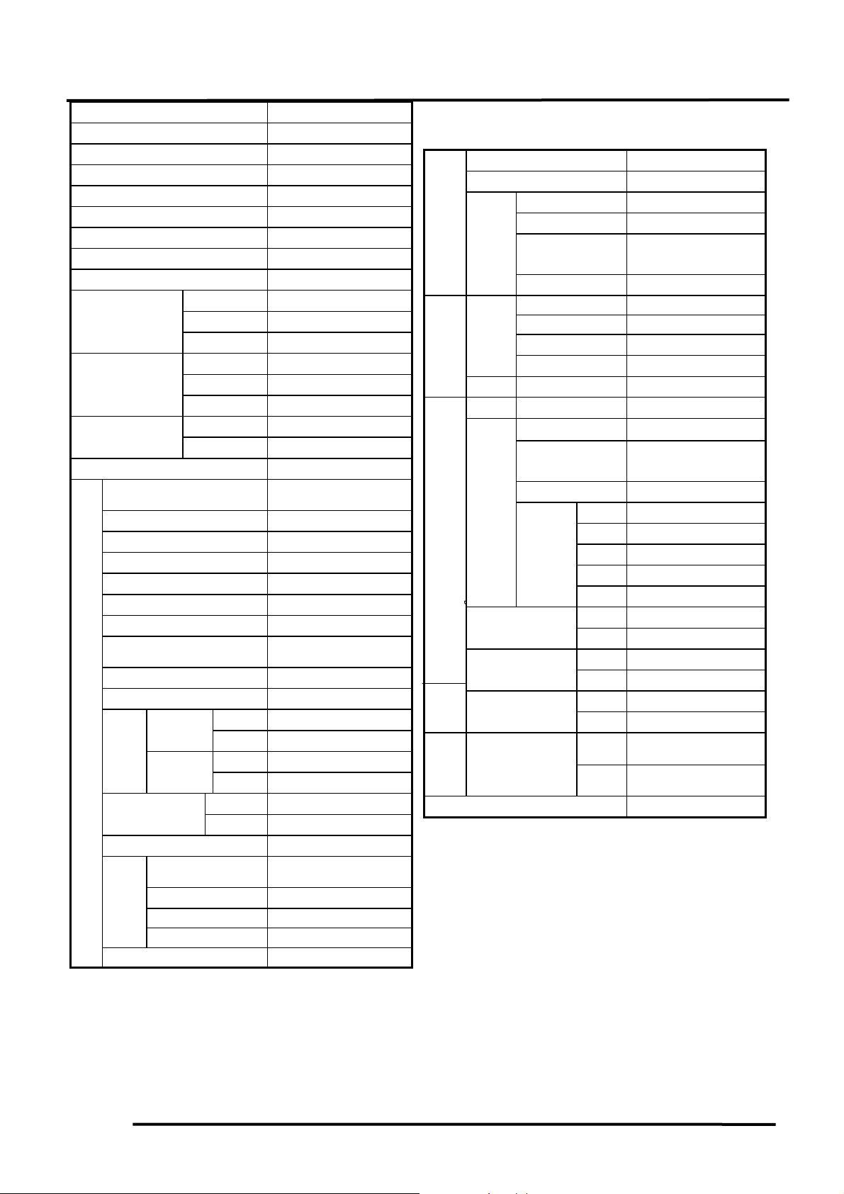
Motorcycle name & Model No. RH30AA
Motorcycle name HIPSTER150
Overall length (mm) 2275
Overall width (mm) 830
Overall height (mm) 1135
Wheel base (mm) 1475
Engine type 4 ∞
Displacement (cc) 149.4
Fuel type 92# nonleaded gasoline
Front wheel 59
Dry weight (kg)
Gross weight(kg)
Tires
Ground clearance (mm) 140
Starting system
Type OHC
Cylinder arrangement Single cylinder
Combustion chamber type Dome head
Valve train SOHC-4V
Bore x stroke (mm) 62 x 49.5
Compression ratio 10
Compression pressure
(kg/cm²)
Max. output (Ps/rpm) 14/9000
Engine
Max. torque (Kg.m/rpm) 1.1/7500
Port
timing
Valve clearance
(cold)
Idle speed (rpm) 1600rpm
Lubrication
System
Oil filter type Wire gauze filter
Cooling Type Air cooling
Rear wheel 80
Total 139
Front wheel 67.5
Rear wheel 91
Total 158.5
Front wheel 3.0-18-4PR
Rear wheel 130/90-15-4PR
Starting motor &
kick starter
13
Intake
(1mm)
Exhaust
(1mm)
Lubrication type
Oil pump type Inner/outer rotor
Oil capacity 1.0L SAE#30
Open 0
Close 30
Open 0
Close 30
Intake 0.06mm
Exhaust 0.06mm
Forced pressure &
wet sump
Air cleaner type Paper element type
Fuel System
Fuel capacity 12.0L
Type CVK
Carburetor
Piston dia. (mm) φ26.5
Venturi
dia.(mm)
Throttle type Piston type
Ignition
System
Electrical
Equipment
Battery Capacity 12V6AH
Moving
Clutch Type Wet multi-disc clutch
Tire pressure
(kg/cm²)(2 riders)
Turning angle
Brake system
type
Damping
Device
Shock absorber
type
Frame type Double cradle
Type CDI
Ignition timing 34.5° ±2/4000rpm
Spark plug NGK-CR8EH9
Spark plug gap 0.60.7mm
Type Permanent gear meshing
Transmission Gear
Operating
ethod m
Type International type
1st gear 2.846
Reductio
n
ratio
2nd gear 2.063
3rd gear 1.4
4th gear 1.130
5th gear 0.923
Front 1.75
Rear 2.25
Left 45°
Right 45°
Front Disk brake
Rear Drum brake
Front Telescope
Rear Double swing
φ26
Foot operated
1-3
Page 6
1. GENERAL INFORMATION
SERVICE PRECAUTIONS
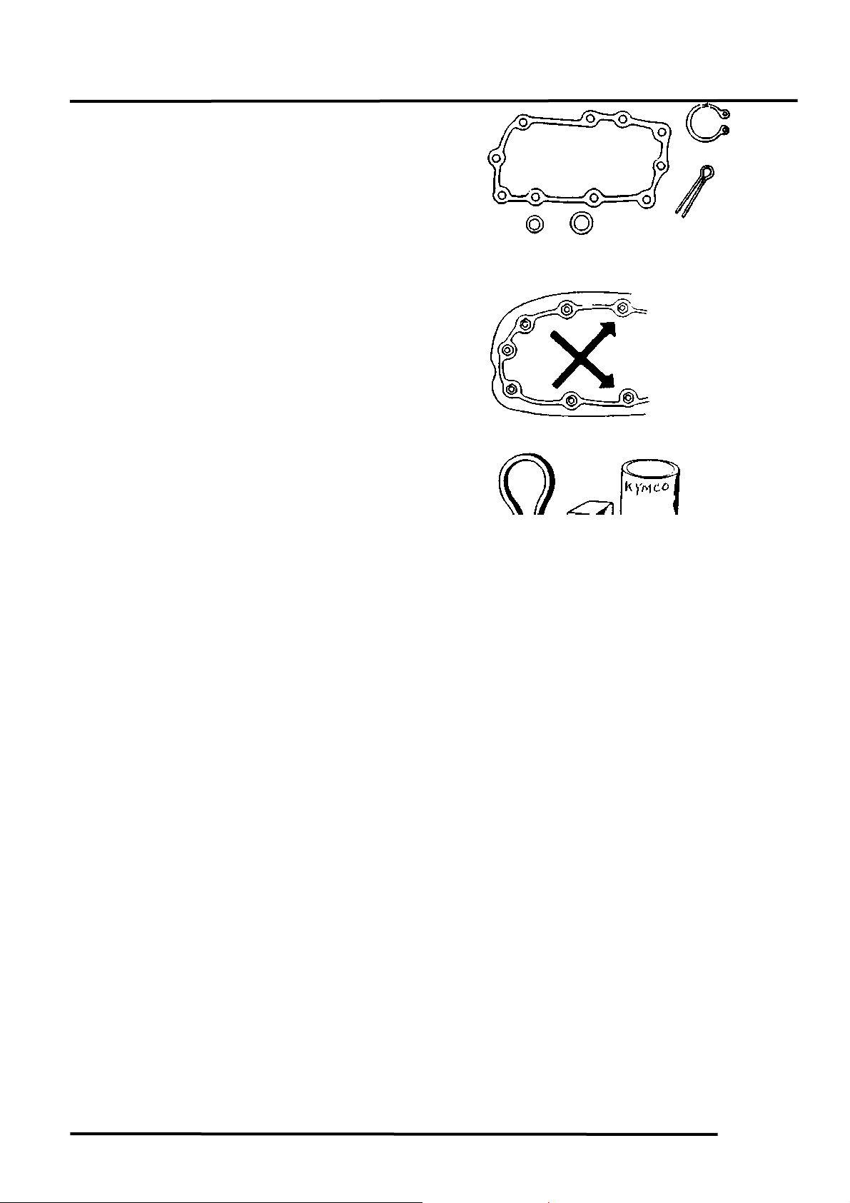
Make sure to install new gaskets, O-rings,
circlips, cotter pins, etc. when
reassembling.
When tightening bolts or nuts, begin with
larger-diameter to smaller ones at several
times, and tighten to the specified torque
diagonally.
Use genuine parts and lubricants.
When servicing the motorcycle, be sure
to use special tools for removal and
installation.
After disassembly, clean removed parts.
Lubricate sliding surfaces with engine oil
before reassembly.
HIPSTER 125/150
Apply or add designated greases and
1-4
Page 7

1. GENERAL INFORMATION
lubricants to the specified lubrication
points.
After reassembly, check all parts for
proper tightening and operation.
When two persons work together, pay
attention to the mutual working safety.
Disconnect the battery negative (-)
terminal before operation.
When using a spanner or other tools,
make sure not to damage the motorcycle
surface.
After operation, check all connecting
points, fasteners, and lines for proper
connection and installation.
When connecting the battery, the positive
(+) terminal must be connected first.
After connection, apply grease to the
battery terminals.
Terminal caps shall be installed securely.
HIPSTER 125/150
If the fuse is burned out, find the cause
1-5
Page 8

1. GENERAL INFORMATION
and repair it. Replace it with a new one
according to the specified capacity.
After operation, terminal caps shall be
installed securely.
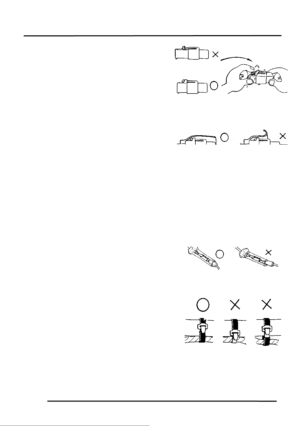
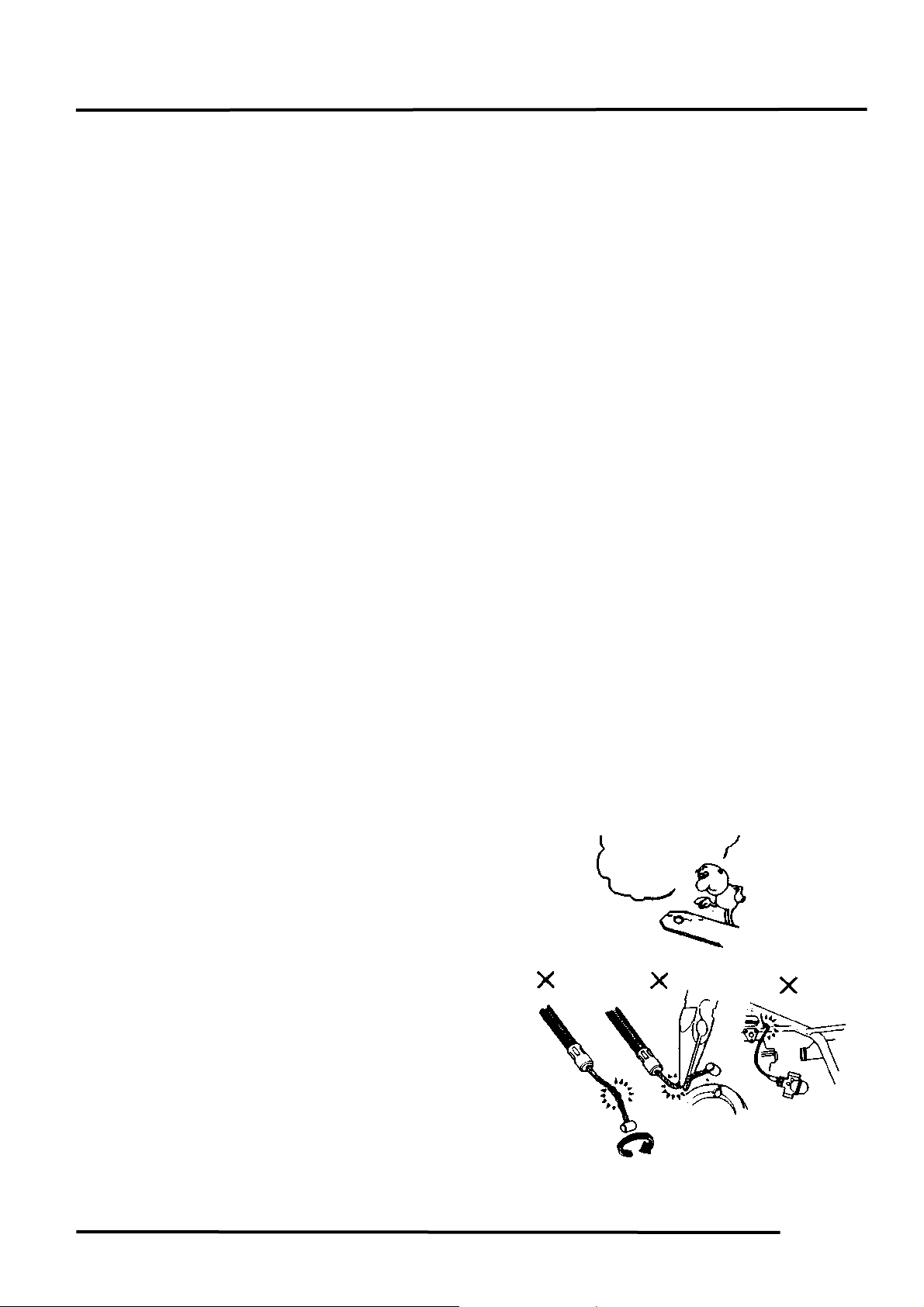
When taking out the connector, the lock
on the connector shall be released before
operation.
Hold the connector body when
connecting or disconnecting it.
Do not pull the connector wire.
Check if any connector terminal is
bending, protruding or loose.
HIPSTER 125/150
Confirm
Capacity
1-6
Page 9
1. GENERAL INFORMATION
The connector shall be inserted
completely.
If the double connector has a lock,
lock it at the correct position.
Check if there is any loose wire.
Check the double connector cover for
proper coverage and installation.
Before connecting a terminal, check for
damaged terminal cover or loose negative
terminal.
Insert the terminal completely.
Check the terminal cover for proper
coverage.
Do not make the terminal cover opening
face up.
Secure wire harnesses to the frame with
their respective wire bands at the
designated locations.
Tighten the bands so that only the
insulated surfaces contact the wire
harnesses.
HIPSTER 125/150
Snapping!
1-7
Page 10
1. GENERAL INFORMATION
N
After clamping, check each wire to make
sure it is secure.
Do not squeeze wires against the weld or
its clamp.
After clamping, check each harness to
make sure that it is not interfering with
any moving or sliding parts.
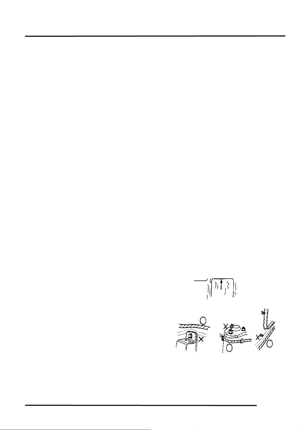
When fixing the wire harnesses, do not
make it contact the parts which will
generate high heat.
Route wire harnesses to avoid sharp
edges or corners. Avoid the projected
ends of bolts and screws.
Route wire harnesses passing through the
side of bolts and screws. Avoid the
projected ends of bolts and screws.
HIPSTER 125/150
o Contact !
1-8
Page 11
1. GENERAL INFORMATION
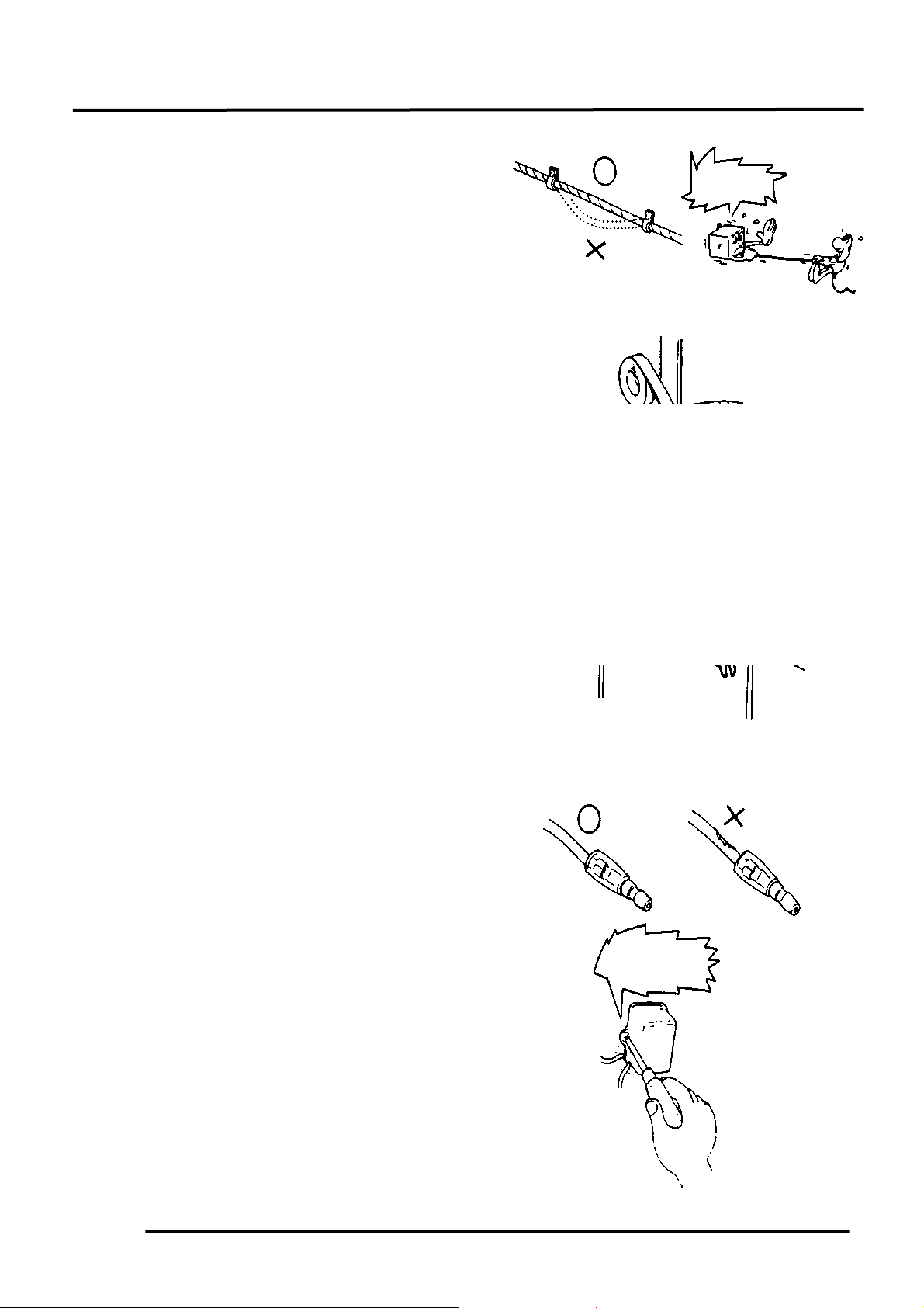
Route harnesses so they are neither
pulled tight nor have excessive slack.
Protect wires and harnesses with
electrical tape or tube if they contact a
sharp edge or corner.
When rubber protecting cover is used to
protect the wire harnesses, it shall be
installed securely.
Do not break the sheath of wire.
If a wire or harness is with a broken
sheath, repair by wrapping it with
protective tape or replace it.
When installing other parts, do not press
or squeeze the wires.
HIPSTER 125/150
Do not press or
squeeze the wire.
Do not pull
too tight!
1-9
Page 12
1. GENERAL INFORMATION
After routing, check that the wire
harnesses are not twisted or kinked.
Wire harnesses routed along with
handlebar should not be pulled tight, have
excessive slack or interfere with adjacent
or surrounding parts in all steering
positions.
When a testing device is used, make sure
to understand the operating methods
thoroughly and operate according to the
operating instructions.
Be careful not to drop any parts.
When rust is found on a terminal, remove
the rust with sand paper or equivalent
before connecting.
Do not bend or twist control cables.
Damaged control cables will not operate
smoothly and may stick or bind.
Do you understand the
instrument? Is the
instrument set correctly?
HIPSTER 125/150
Remove Rust !
1-10
Page 13
1. GENERAL INFORMATION
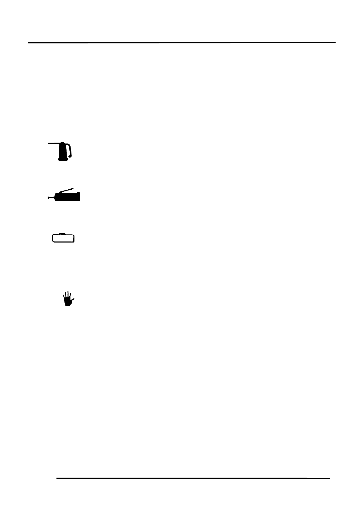
Symbols:
The following symbols represent the
servicing methods and cautions included
in this service manual.
: Apply engine oil to the
specified points. (Use
designated engine oil for
Engine Oil
Grease
Special
lubrication.)
: Apply grease for
lubrication.
: Use special tool.
: Caution
: Warning
HIPSTER 125/150
1-11
Page 14
1. GENERAL INFORMATION
m
HIPSTER 125/150
TORQUE VALUES
STANDARD TORQUE VALUES
5mm bolt, nut
6mm bolt, nut
8mm bolt, nut
10mm bolt, nut
12mm bolt, nut
Torque specifications listed below are for important fasteners.
ENGINE
Cylinder head bolt A
Cylinder head bolt B
Oil filter screen cap
Exhaust muffler joint lock nut
Valve adjusting lock nut
Oil bolt
Cylinder bolt
A.C. generator bolt
Cylinder head cover bolt
Oil pump bolt
Oil filter lock nut
Rocker arm lock bolt
Cylinder head lock bolt
Cylinder bolt
Crankcase assembly bolt
Crankshaft damper bolt
Right crankcase cover bolt
Left crankcase cover bolt
A.C. generator coil lock bolt
Starter gear set plate bolt
Carburetor lock bolt
Item Torque (kg-m) Ite
0.450.6
0.81.2
1.82.0
3.04.0
5.06.0
Item Q‘ty Thread dia.(mm) Torque (kg-m) Remarks
2
2
1
2
2
1
2
1
4
2
1
3
1
2
10
1
8
4
4
1
2
5mm screw
6mm nut, SH bolt
6mm flange bolt, nut
8mm flange bolt, nut
10mm flange bolt, nut
8
8
30
6
5
12
6
14
6
6
16
8
8x79
6x22
6
6x25
6
6
5
6
6
2.83.2
2.83.2
1.53.0
0.81.2
1.41.8
2.03.0
0.81.2
4.05.2
0.81.2
0.71.1
1.53.0
1.52.0
1.52.0
0.81.2
0.81.5
0.81.2
0.81.2
0.81.2
0.41.7
1.01.6
0.81.2
Torque (kg-m)
0.350.5
0.71.1
1.01.4
2.03.0
3.54.5
Double end bolt
Double end bolt
Double end bolt
FRAME
Steering stem lock nut
Front axle nut
Rear axle nut
Rear shock absorber upper mount bolt
Rear shock absorber lower mount bolt
Rear fork pivot nut
Handlebar lock bolt
Rear driven gear bolt
Rear brake panel bolt
Item Q‘ty Thread dia.(mm) Torque (kg-m) Remarks
1
1
1
2
2
1
4
4
1
22
14
16
10
10
12
6
8
8
6.09.0
5.57.0
6.08.0
3.04.0
3.04.0
5.57.0
6.09.0
1.82.0
1.82.5
1-12
Page 15

1. GENERAL INFORMATION
SPECIAL TOOLS
HIPSTER 125/150
Flywheel puller E005
Bearing puller 18mm E008
Lock nut socket wrench E010
Tappet adjuster E012
Oil seat & bearing install E014
Bearing puller 15mm E018
Bearing puller 12mm E020
Flywheel holder E021
Crankshaf bearing puller E030
Bearing puller 10mm E031
Race cone install F005
Tool Name Tool No. Remarks Ref. Page
1-13
Page 16
1. GENERAL INFORMATION
LUBRICATION POINTS
Front Brake Fluid Tube
Grease
Throttle Cable
HIPSTER 125/150
Engine Oil
Clutch Cable
Grease
Speedometer Cable
1-14
Page 17
1. GENERAL INFORMATION
t
r
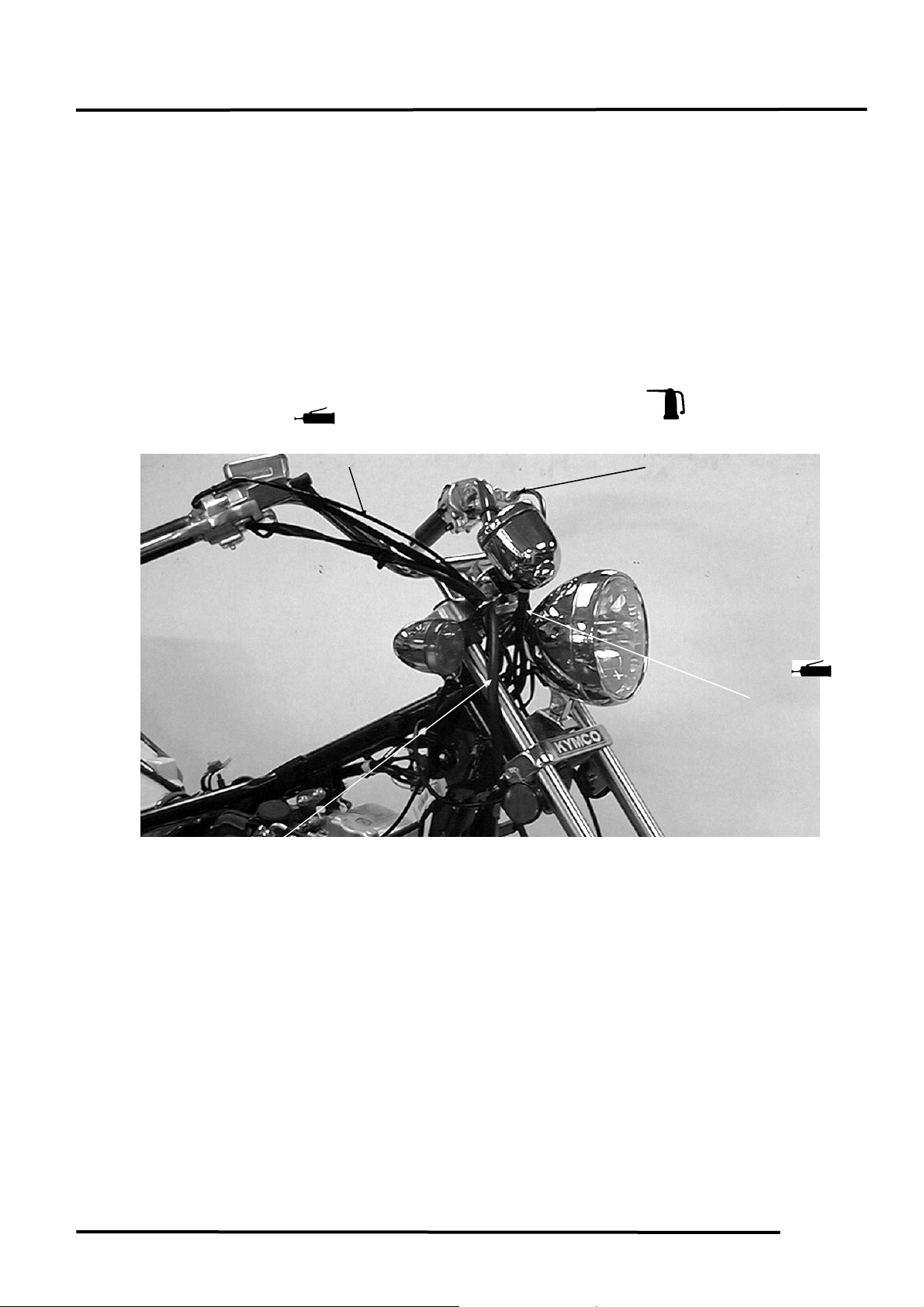
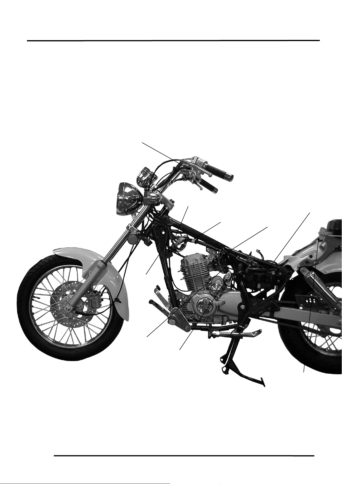
CABLE & HARNESS ROUTING
Handlebar Switch
Connectors
Ignition Coil
Fuel Tube
Ignition Switch
CDI Uni
Wire Harness
HIPSTER 125/150
A.C. Generator
Wire Connector
Fuel Filte
Taillight Wire
Connector
1-15
Page 18
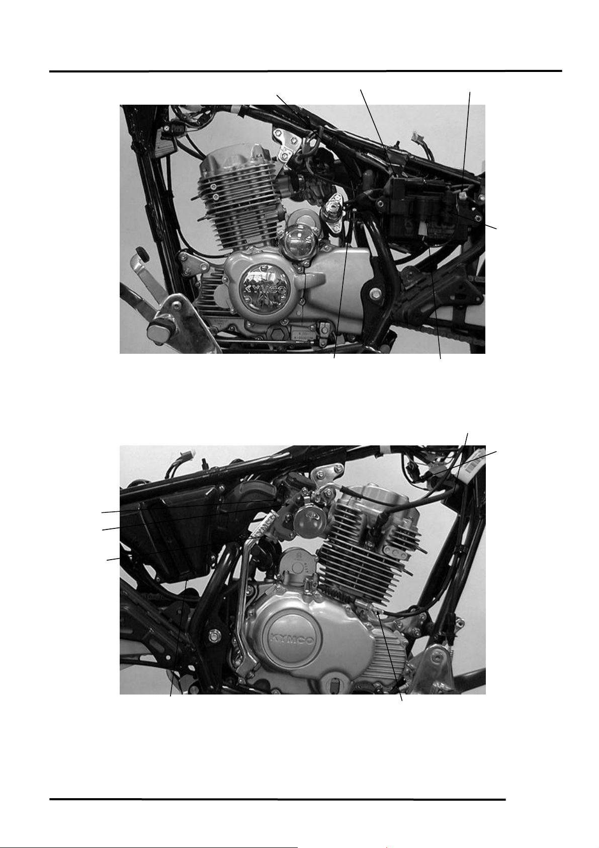
1. GENERAL INFORMATION
N
r
t
r
A.C.V. Vacuum
Tube
A.C.V.
Accelerating Pump
Cable
Purge Control
Valve
Air Cleane
Vacuum Tube
Starter Relay
Starter Motor Wire
Throttle Cable
egative Cable
Clutch Cable
HIPSTER 125/150
Battery Positive
Cable
Fuse Box
Winke
CDI Uni
A.I.C.V.
Ignition Coil
Wire
1-16
Page 19
1. GENERAL INFORMATION
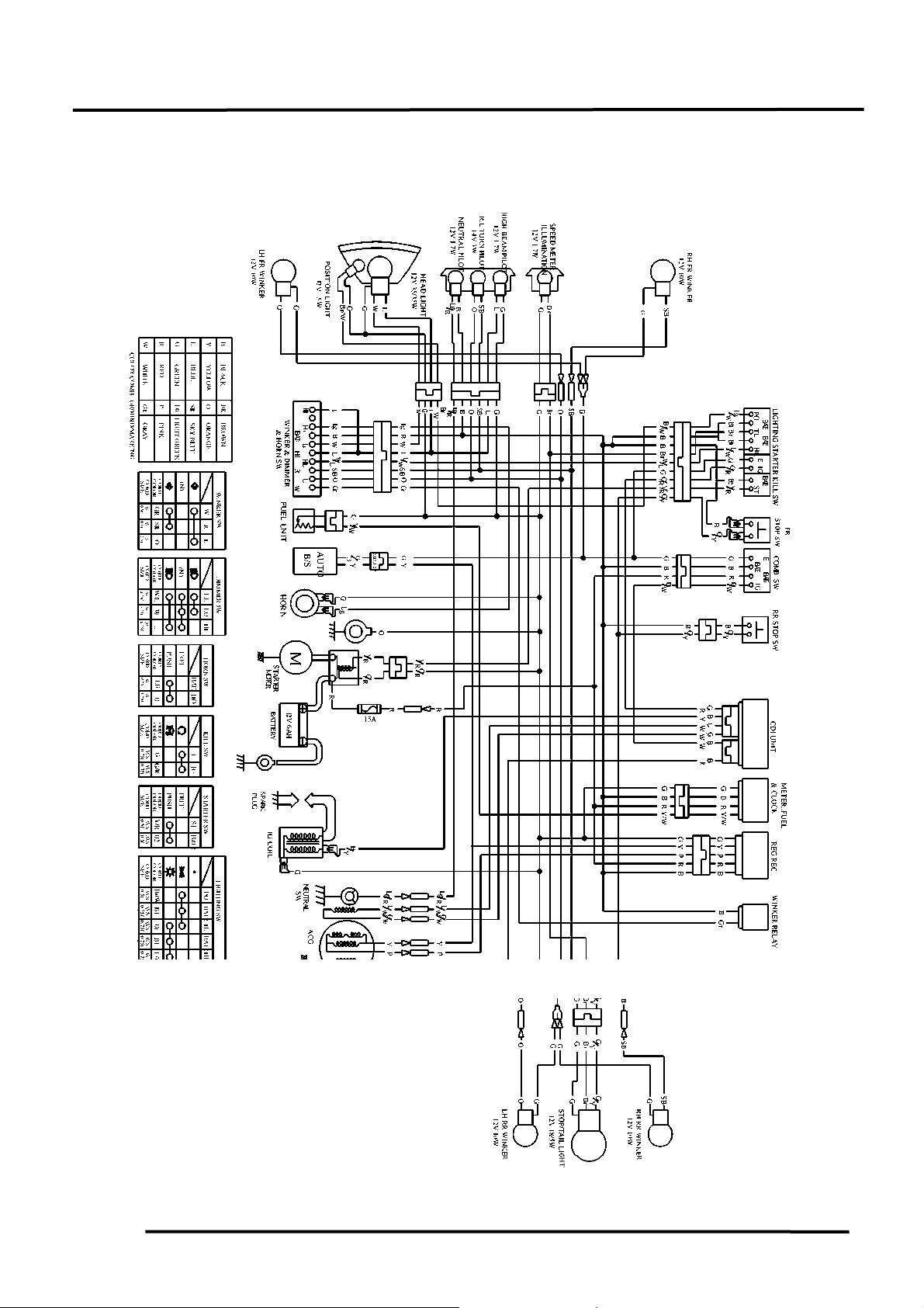
WIRING DIAGRAM
HIPSTER 125/150
1-17
Page 20
1. GENERAL INFORMATION
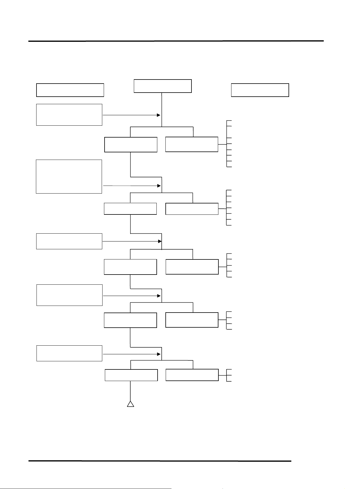
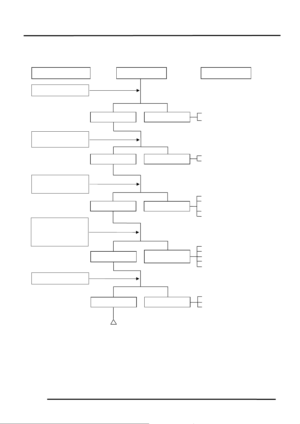
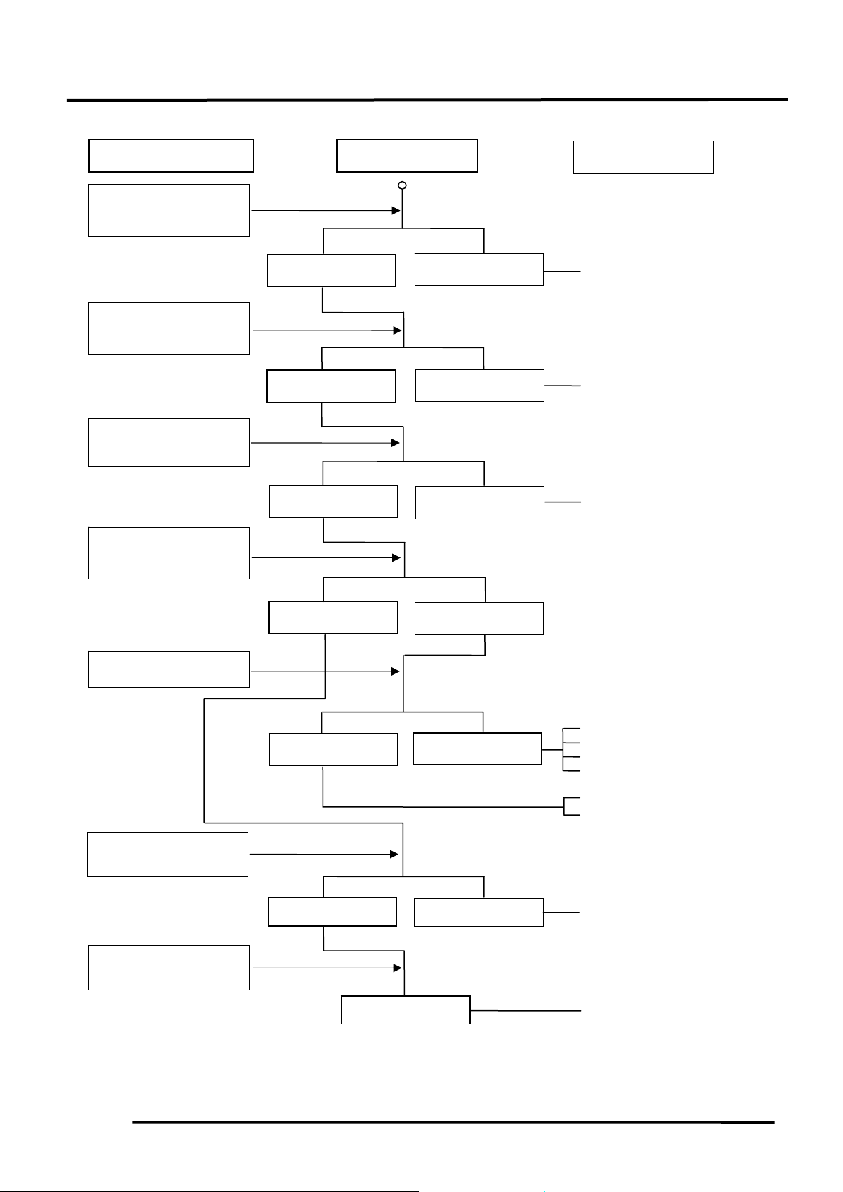
TROUBLESHOOTING
ENGINE WILL NOT START OR IS HARD TO START
Inspection/Adjustment
Check if fuel reaches
carburetor by loosening
drain screw
Remove spark plug and
install it into spark plug
cap to test spark by
connecting it to engine
ground
Test cylinder
compression
Start engine by
follow-ing normal
starting procedure
Remove spark plug and
inspect again
Fuel reaches
carburetor
Spark jumps
Normal
compression
Engine does not
fire
Dry spark plug
Symptom
Fuel does not
reach carburetor
Weak or no spark
Low or no
compression
Engine fires but
does not start
Wet spark plug
HIPSTER 125/150
Probable Cause
Empty fuel tank
Clogged fuel line between fuel
tank and carburetor
Clogged float oil passage
Clogged fuel filter
Clogged charcoal canister
Clogged auto fuel valve strainer
Faulty auto fuel valve passage
Clogged carburetor air balance
tube
Faulty spark plug
Fouled spark plug
Faulty CDI unit
Faulty pulser coil
Faulty exciter coil
Faulty ignition switch
Broken or shorted ignition coil
wire
Faulty or slipping clutch
Valve clearance too small
Valve stuck open
Worn cylinder and piston rings
Leaking cylinder head gasket
Faulty choke control system
Leaking intake manifold
Incorrect ignition timing
Incorrectly adjusted pilot screw
Flooded carburetor
Throttle valve excessively open
Clogged air cleaner
1-18
Page 21
1. GENERAL INFORMATION
POOR PERFORMANCE (ESPECIALLY AT IDLE AND LOW SPEEDS)
Inspection/Adjustment Symptom
Check ignition timing
Faulty CDI unit
Faulty pulser coil
Mixture too lean (turn screw in)
Mixture too rich (turn screw
out)
Faulty intake manifold gasket
Carburetor not securely
tightened
Damaged insulator rubber
Broken vacuum tube
Faulty or fouled spark plug
Faulty CDI unit
Faulty A.C. generator
Faulty ignition coil
Faulty ignition switch
Faulty A.C. generator
Damaged vacuum tube
Clogged air vent hole
Check carburetor pilot
screw adjustment
Check carburetor gasket
for air leaks
Remove spark plug and
install it into spark plug
cap to test spark by
connecting it to engine
ground
Check A.C. generator
Correct
Correctly adjusted
No air leak
Good spark
Good
Incorrect
Incorrectly adjusted
Air leaks
Weak or inter-
mittent spark
Faulty
HIPSTER 125/150
Probable Cause
1-19
Page 22
1. GENERAL INFORMATION
N
t
r
t
r
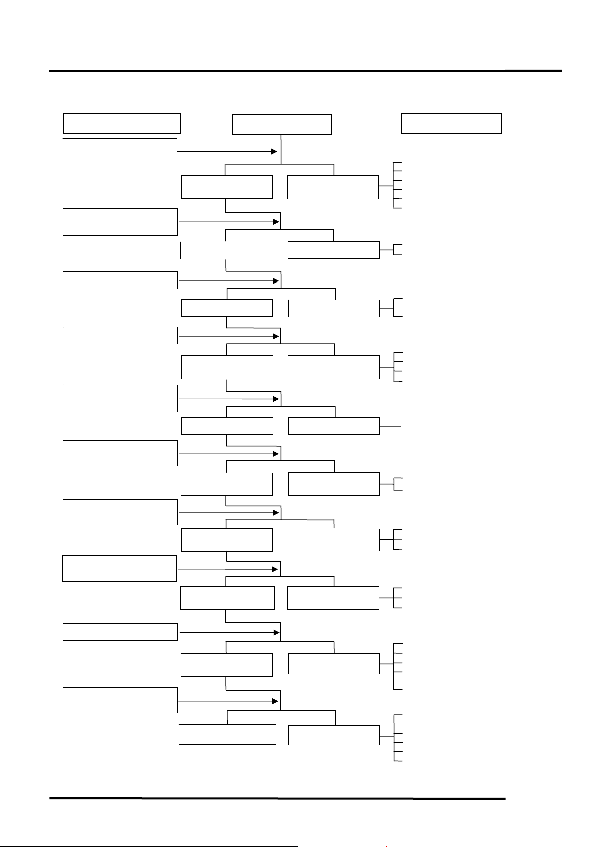
POOR PERFORMANCE (ENGINE LACKS POWER)
Inspection/Adjustment
Start engine and accelerate
lightly for observation
Check ignition timing using
a timing light
Check valve clearance
Test cylinder compression
Check carburetor for
clogging
Remove spark plug and
inspect
Check crankcase for oil
level and condition
Remove cylinder head oil
pipe bolt and inspect
Check for engine overheating
Rapidly accelerate or run at
high speed
Engine speed
increases
Correct
Correct
ormal
compression
Not clogged
Plug not fouled o
discolored
Correct and no
contaminated
Valve train lubricated
properly
Engine does no
overheats
Engine does not knock
Symptom
Engine speed does not
increase sufficiently
Incorrect
Incorrect
Abnormal
compression
Clogged
Plug fouled or
discolored
Incorrect o
contaminated
Valve train not
lubricated properly
Engine overheats
Engine knocks
HIPSTER 125/150
Probable Cause
Clogged air cleaner
Poor fuel flow (Restricted)
Clogged fuel tank cap breather hole
Clogged exhaust muffler
Carburetor fuel level too low
Clogged carburetor high speed fuel
passage
Faulty CDI unit
Faulty pulser coil
Improper valve clearance
adjustment
Excessively worn valve seat
(protruded valve stem)
Improper valve and seat contact
Worn cylinder and piston rings
Leaking cylinder head gasket
Improper valve timing
Clean and unclog
Fouled spark plug
Incorrect heat range plug
Oil level too high
Oil level too low
Oil not changed
Clogged oil cooler
Clogged oil line
Faulty oil pump
Worn cylinder and piston rings
Mixture too lean
Poor quality fuel
Excessive carbon buildup in
combustion chamber
Ignition timing too advanced
Excessive carbon build-up in
combustion chamber
Poor quality fuel
Clutch slipping
Mixture too lean
Ignition timing too advanced
1-20
Page 23
1. GENERAL INFORMATION
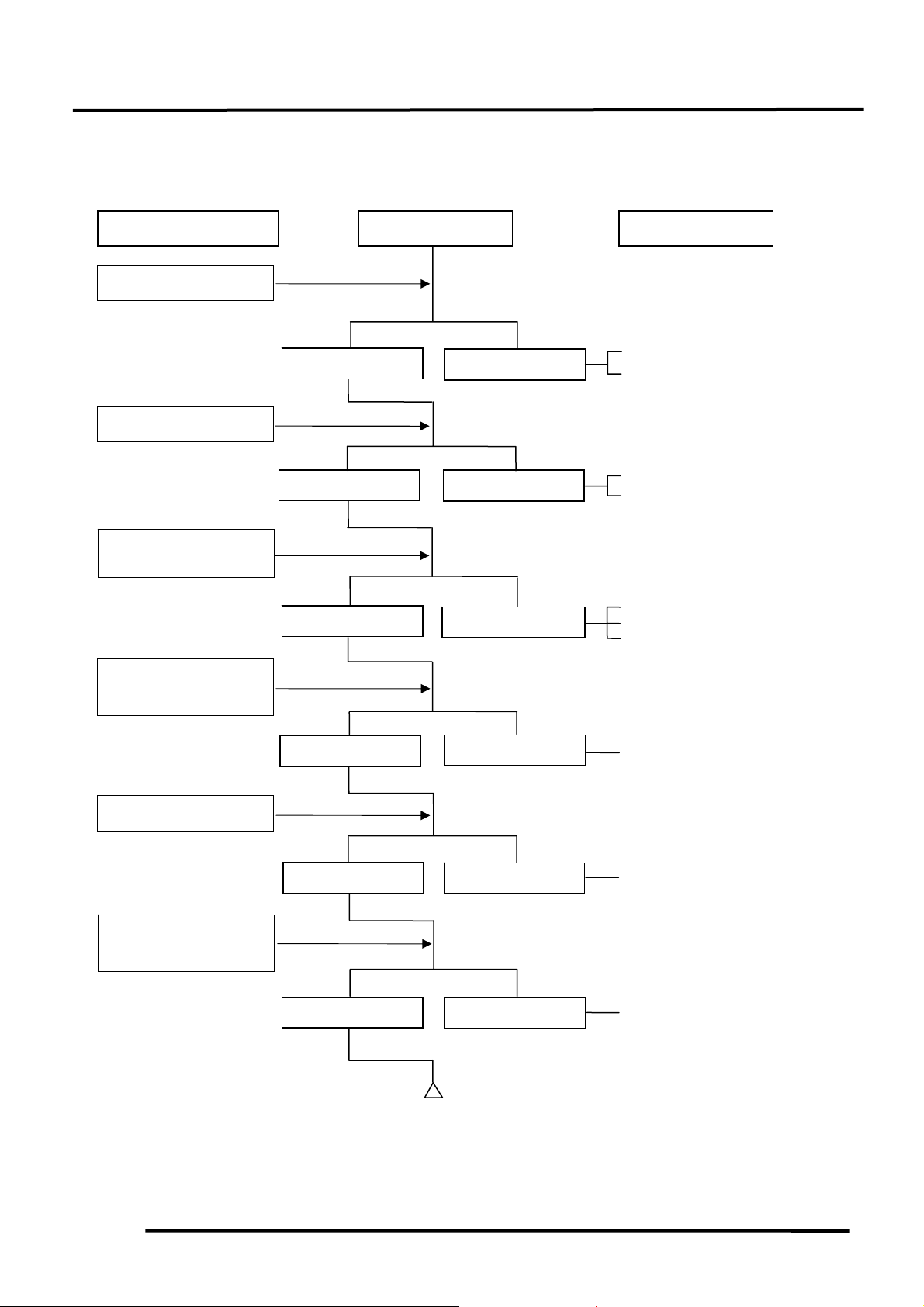
POOR PERFORMANCE (AT HIGH SPEED)
Inspection/Adjustment Symptom
Check ignition timing
Correct
Check valve clearance
Correct
Check fuel filter for
fuel supply
Fuel flows freely
Check carburetor for
clogged jets
Not clogged
Check valve timing
Correct
Check valve spring
tension
Not weakened
Fuel f l ow restricted
Incorrect
Incorrect
Clogged
Incorrect
Weak spring
HIPSTER 125/150
Probable Cause
Faulty CDI unit
Faulty pulser coil
Improperly adjusted valve clearance
Worn valve seat
Empty fuel tank
Clogged fuel filter
Clogged fuel tank cap breather
hole
Clean and unclog
Cam timing gear aligning marks
not aligned
Faulty spring
1-21
Page 24
1. GENERAL INFORMATION
B
t
B
HIPSTER 125/150
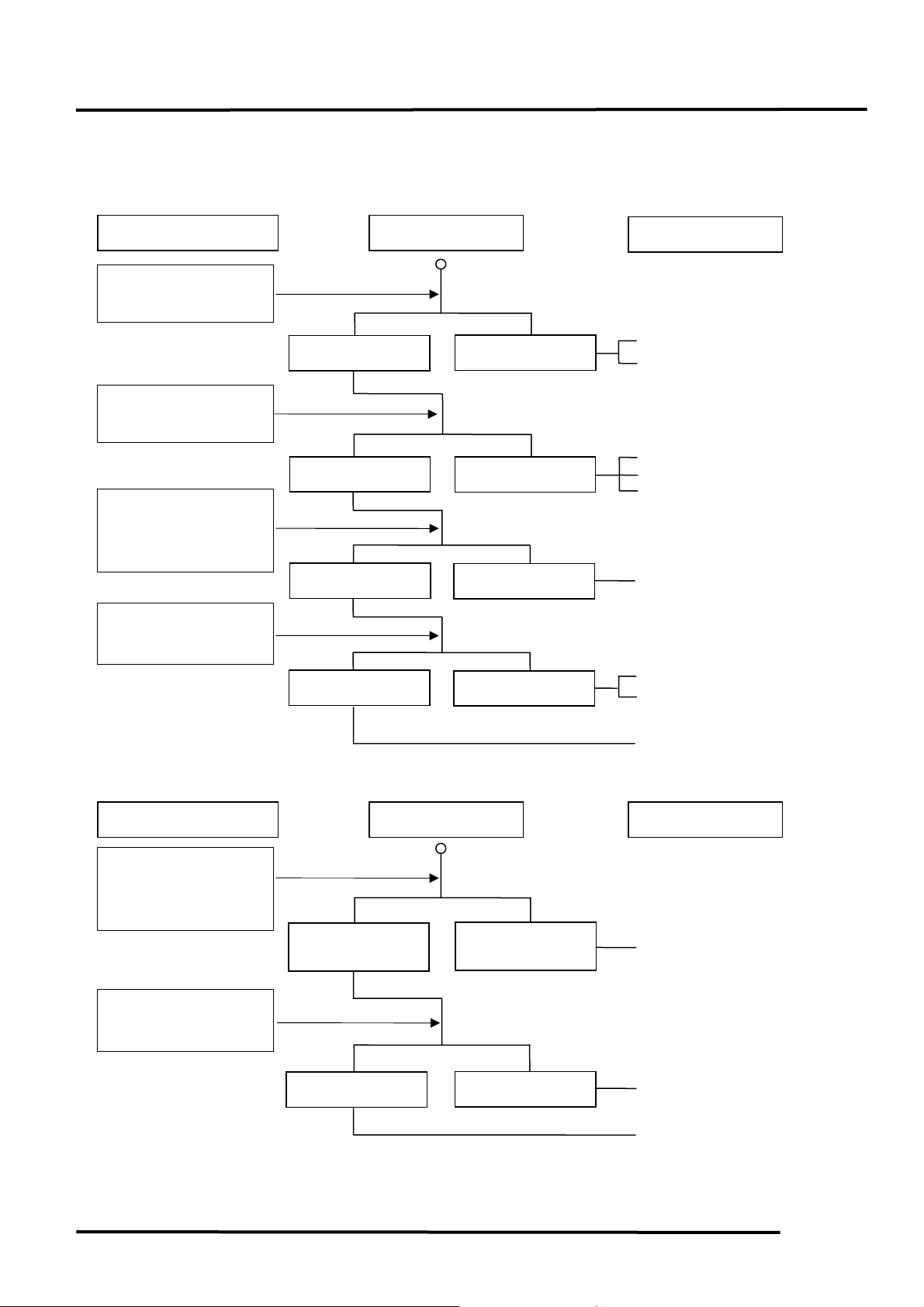
POOR CHARGING (BATTERY OVER DISCHARGING OR OVERCHARGING)
Undercharging
Inspection/Adjustment Symptom
Probable Cause
Start engine and test
limit voltage between
battery terminals
Measure resistance
between AC generator
coil terminals
Connect battery (+) wire
to regulator/rectifier
coupler red wire and
battery (-) wire to engine
ground and test voltage
Check regulator/rectifier
coupler for loose
connection
Normal voltage
Normal
Normal voltage
Voltage does no
increase
Resistance too high
No voltage
Dead battery
Faulty battery
Faulty coil
Broken pink and yellow wires
Shorted pink and yellow wires
Broken red wire
Normal
Abnormal
Faulty regulator/rectifier
Poorly connected coupler
Faulty A.C. generator
Overcharging
Inspection/Adjustment Symptom
Probable Cause
Connect battery (+) wire
to regulator/rectifier
coupler black wire and
battery (-) wire to engine
ground and test voltage
Check regulator/rectifier
coupler for loose
connection
attery has voltage
with ignition switch
“ON”
Normal
attery has no
voltage with ignition
switch “ON”
Abnormal
Broken black wire
Poorly connected coupler
Faulty regulator/rectifier
1-22
Page 25
1. GENERAL INFORMATION
p
NO SPARK AT SPARK PLUG
Inspection/Adjustment Symptom
Replace with a new spark
lug and inspect again
Weak or no spark
Check spark plug cap
and ignition coil wire for
looseness
Not loose
Check CDI unit coupler
for looseness
Normal
Measure resistance
between CDI unit
coupler wire terminals
Normal
Check related parts
Normal
Check CDI unit with a
CDI unit tester
Normal
Check ignition coil with
a CDI unit tester
Abnormal
Good spark
Loose
Abnormal
Abnormal
Abnormal
Abnormal
HIPSTER 125/150
Probable Cause
Faulty old spark plug
Loose spark plug cap
Poorly connected coupler
Faulty ignition switch
Faulty exciter coil
Faulty pulser coil
Faulty ignition coil
Broken wire harness
Poorly connected coupler
Faulty CDI unit
Faulty ignition coil
1-23
Page 26

2. INSPECTION/ADJUSTMENT
2
__________________________________________________________________________________
HIPSTER125/150
__________________________________________________________________________________
__________________________________________________________________________________
__________________________________________________________________________________
__________________________________________________________________________________
INSPECTION/ADJUSTMENT
__________________________________________________________________________________
SERVICE INFORMATION------------------------------------------------ 2- 1
MAINTENANCE SCHEDULE-------------------------------------------- 2- 2
FUEL LINE/FILTER-------------------------------------------------------- 2- 3
THROTTLE OPERATION------------------------------------------------- 2- 3
AIR CLEANER -------------------------------------------------------------- 2- 4
SPARK PLUG---------------------------------------------------------------- 2- 4
VALVE CLEARANCE----------------------------------------------------- 2- 5
CARBURETOR IDLE SPEED -------------------------------------------- 2- 5
IGNITION TIMING--------------------------------------------------------- 2- 6
CYLINDER COMPRESSION--------------------------------------------- 2- 6
ENGINE OIL----------------------------------------------------------------- 2- 7
DRIVE CHAIN -------------------------------------------------------------- 2- 7
BRAKE SHOE/BRAKE PEADAL---------------------------------------- 2- 8
CLUTCH---------------------------------------------------------------------- 2- 8
BRAKE FLUID -------------------------------------------------------------- 2- 8
SUSPENSION---------------------------------------------------------------- 2- 9
NUTS/BOLTS/FASTENERS ---------------------------------------------- 2- 9
WHEELS/TIRES ------------------------------------------------------------ 2- 9
STEERING HANDLEBAR ------------------------------------------------ 2-10
2
2-0
Page 27
2. INSPECTION/ADJUSTMENT
HIPSTER125/150
SERVICE INFORMATION
GENERAL
WARNING
•Before running the engine, make sure that the working area is well-ventilated. Never run the
engine in a closed area. The exhaust contains poisonous carbon monoxide gas which may
cause death to people.
•Gasoline is extremely flammable and is explosive under some conditions. The working area
must be well-ventilated and do not smoke or allow flames or sparks near the working area or
fuel storage area.
SPECIFICATIONS
ENGINE CHASSIS
Throttle grip free play : 26mm Rear brake free play : 1020mm
Spark plug gap : 0.60.7mm Brake fluid : DOT-3
Spark plug specification : DR8EA
Valve clearance : IN: 0.06mm Cold Engine: IN: 0.05mm
EX: 0.06mm EX: 0.05mm
Cylinder compression : 150cc: 13kg/cm²
125cc: 13kg/cm²
Ignition timing : 34.5±2°/4000rpm
Idle speed : 1600±100rpm
Engine oil capacity:
At disassembly : 1.0 liter
At change : 0.9 liter
TIRE PRESSURE
TIRE SIZE:
Front : 3.00–18
Rear : 130/90–15
TORQUE VALUES
Front axle nut 5.57.0kg-m
Rear axle nut 6.08.0kg-m
Front 1.75kg/cm² 1.75kg/cm²
Rear 2.0kg/cm² 2.25kg/cm²
–4PR
–4PR
1 Rider 2 Riders
2-1
Page 28

2. INSPECTION/ADJUSTMENT
r
MAINTENANCE SCHEDULE
Perform the periodic maintenance at each scheduled maintenance period.
I: Inspect, and Clean, Adjust, Lubricate, Refill, Repair or Replace if necessary.
A: Adjust C: Clean R: Replace T : Tighten
HIPSTER125/150
Frequency
Item
Engine oil
Whicheve
comes
first Ö
Ø
1000
New
R
motorcycle
300km
200
0
Regular Service Mileage (km)
300
400
500
600
700
0
0
0
0
0
R
R
R
800
0
900
1000
1100
1200
0
0
0
0
R
R
Engine oil filter
C C C
screen
Fuel filter screen R
Valve clearance
New
A
motorcycle
300km
A
A
A
Carburetor I I I
Air Cleaner Note 2,3 I R I R I R
Spark plug Clean at every 3000km and replace if necessary
Brake system I I I I I I
Drive chain A A A A A A
Suspension I I
Nuts, bolts, fasteners I T I T
Tire I I I
Steering head bearing I I
• In the interest of safety, we recommend these items should be serviced only by an authorized
KYMCO motorcycle dealer.
Note: 1. For higher odometer readings, repeat at the frequency interval established here.
2. Service more frequently when riding in dusty or rainy areas.
3. Service more frequently when riding for long distance, in rain or at full throttle.
2-2
Page 29
2. INSPECTION/ADJUSTMENT
r
t
t
t
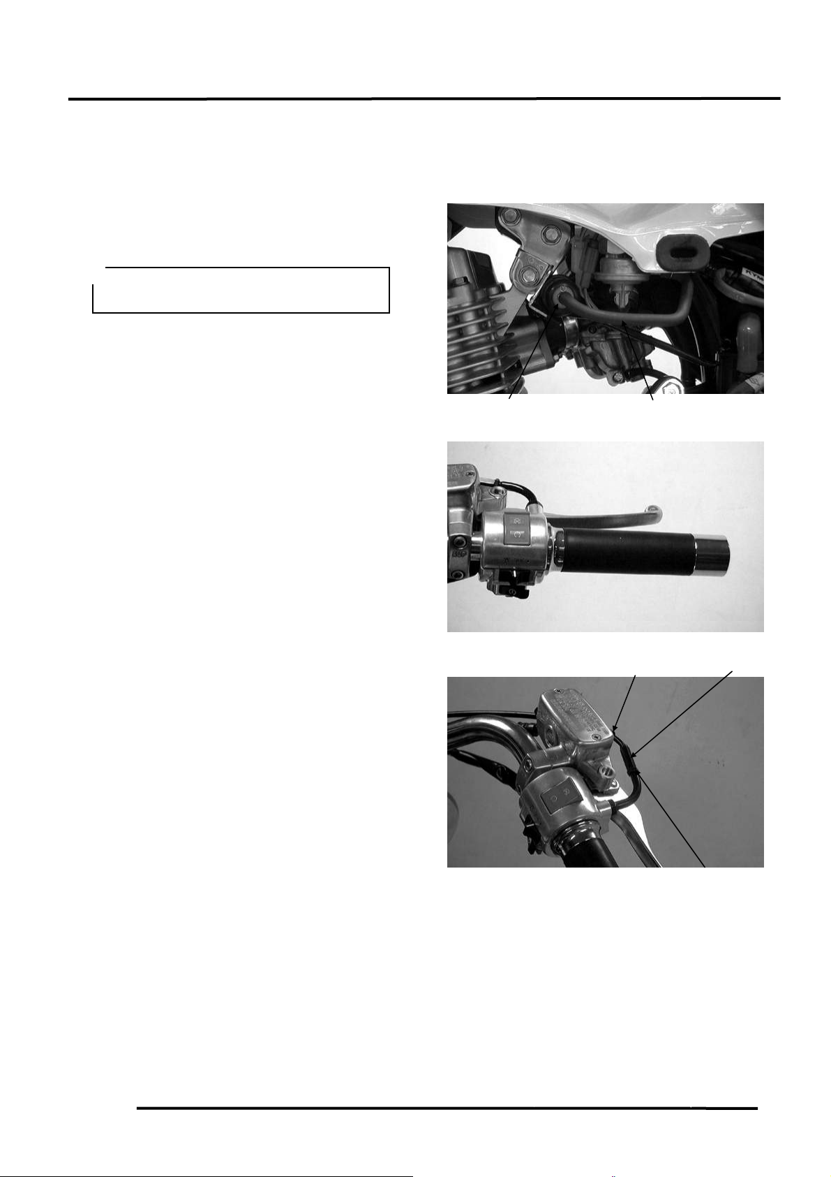
FUEL LINE/FILTER
Check the fuel lines and replace any parts
which show signs of deterioration, damage
or leakage.
Do not smoke or allow flames or sparks
in your working area.
THROTTLE OPERATION
Check for smooth throttle grip movement in
all steering positions.
Measure the throttle grip free play.
Free Play: 26mm
Adjust the throttle grip free play by turning
the adjusting nut on the throttle cable.
Slide the dust boot out and adjust by
loosening the lock nut and turning the
adjusting nut.
Check if the punch mark on the carburetor
accelerating pump is aligned.
Align the punch mark by turning the
adjusting nut at the accelerating pump cable.
Fuel Filte
HIPSTER125/150
Fuel Line
Dust Boo
Adjusting Nu
Lock Nu
2-3
Page 30
2. INSPECTION/ADJUSTMENT
t
y
y
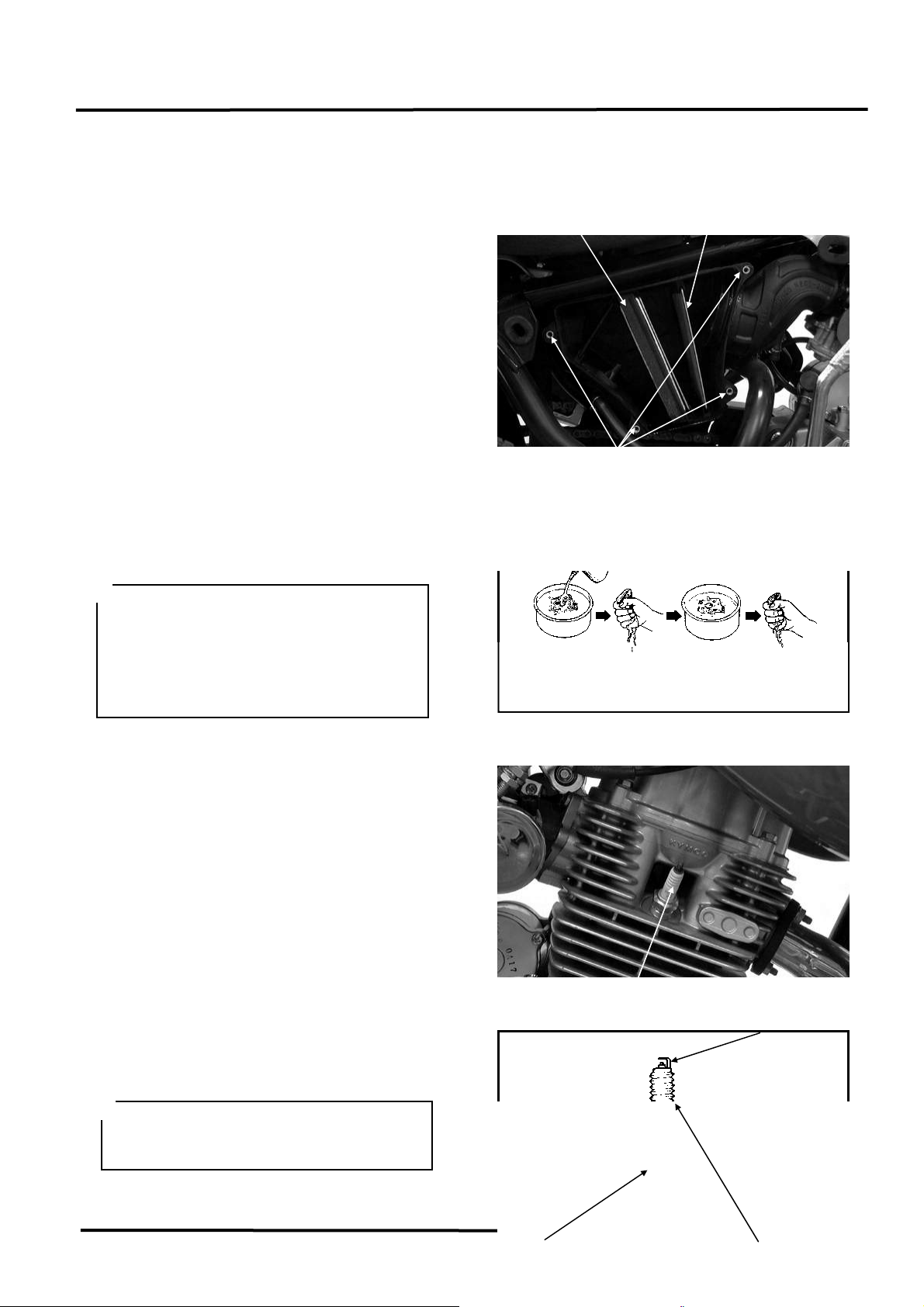
AIR CLEANER
AIR CLEANER REPLACEMENT
Remove the right side cover. Remove the
two screws attaching the emission control
system.
Remove the air cleaner case cover screws
and the cover.
Remove the air cleaner screen and element.
Check the element and replace it with a new
one if it is excessively dirty or damaged.
CHANGE INTERVAL
More frequent replacement is required when
riding in unusually dusty or rainy areas.
• If the air cleaner is installed
improperly, dust may be sucked into
the cylinder directly to reduce the
engine horse-power and affect engine
service life.
• Do not wash the element in any solvent
SPARK PLUG
Remove the spark plug.
Check the spark plug for wear, damage and
fouling deposits.
Clean any fouling deposits with a spark plug
cleaner or a wire brush.
Specified Spark Plug: DR8EA
Measure the spark plug gap.
Spark Plug Gap: 0.60.7mm
When installing, first screw in the spark
plug by hand and then tighten it with a
spark plug wrench.
HIPSTER125/150
Elemen
Wash
Screw
Squeeze out
and dr
Spark Plug
Screen
Engine
oil
Gap, Wear, and
Fouling Deposits
Squeeze out
and dr
2-4
Page 31

2. INSPECTION/ADJUSTMENT
Cracks
Damage
VALVE CLEARANCE
Inspect and adjust valve clearance while
the engine is cold (below 35).
Remove four bolt.
Remove the cylinder head cover protector..
Remove the cylinder head cover.
Rotate the generator flywheel to locate the
camshaft on the top dead center (TDC) and
align the “T” mark on the flywheel with the
mark on the left crankcase cover.
After adjustment, rotate the crankshaft
several turns to make sure that the valve
clearance is correct.
Inspect and adjust the valve clearance.
Valve Clearance: IN : 0.06mm
EX: 0.06mm
Cold Engine: IN: 0.05mm
EX: 0.05mm
Loosen the lock nut and adjust by turning the
adjusting bolt.
Special
Tappet Adjust E012
Check the valve clearance again after the
lock nut is tightened.
CARBURETOR IDLE SPEED
The engine must be warm for accurate
idle speed inspection and adjustment.
Turn the throttle stop screw to obtain the
specified idle speed.
Idle Speed: 1600±100rpm
When the engine misses or run erratic, adjust
Washer
Deformation
the pilot screw.
“T” Mark
Feeler Gauge
HIPSTER125/150
Bolts
2-5
When adjusting the carburetor, make
sure to use a E/M tester.
Page 32

2. INSPECTION/ADJUSTMENT
t
Throttle Stop Screw
IGNITION TIMING
• The CDI unit is not adjustable.
• If the ignition timing is incorrect,
check the ignition system.
Remove the ignition timing eye hole cap on
the left crankcase cover.
Check the ignition timing with a timing light.
When the engine is running at idle speed, the
ignition timing is correct if the index mark
on the left crankcase cover aligns with the
“F” mark on the flywheel.
CYLINDER COMPRESSION
Warm up the engine before compression test.
Stop the engine, then remove the spark plug
and insert a compression gauge.
Open the throttle valve fully and crank the
engine with the starter motor or kick lever.
Measure the compression.
Compression: 13kg/cm²
If the compression is low, check for the
following:
Leaky valves
Valve clearance too small
Leaking cylinder head gasket
Worn piston rings
Worn piston/cylinder
If the compression is high, it indicates that
Pilot Screw
HIPSTER125/150
carbon deposits have accumulated on the
combustion chamber and the piston head.
Eye Hole
Timing Ligh
“F” Mark
Compression Gauge
2-6
Page 33

2. INSPECTION/ADJUSTMENT
g
t
t
ENGINE OIL
When checking the oil level, place the
motorcycle on its main stand on level
ground for oil level check.
After the engine is stopped for 10 minutes,
check if the oil level is between the upper and
lower limits through the wash window.
If the oil level is low, add the recommended
oil to the proper level.
Recommended Oil: SAE30W#
After oil change, be sure to tighten the drain
bolt securely.
Check the drain bolt washer for damage.
Oil Capacity: At disassembly : 1.0 liter
At change : 0.9 liter
HIPSTER125/150
Watch Window Oil Filter Screen Cap
Engine Oil Filter Screen Cleaning
Remove the oil filter screen cap.
Remove the oil filter screen and spring and
then clean with compressed air.
Be careful not to install the oil filter
screen in the reverse direction to avoid
engine damage.
DRIVE CHAIN
Check the drive chain slack.
Specified Slack: 12cm
Drive Chain Adjustment:
1. Loosen the rear axle nut.
2. Adjust the right and left adjusting nuts to
align the right punch mark with the left
punch mark.
3. Turn the rear wheel to see if the drive
chain slack is within the specified range.
4. Tighten the rear axle nut.
After drive chain adjustment, check the
rear brake pedal free play and adjust if
necessary.
Sprin
Spring
Oil Filter Screen
Rear Axle Nu
Oil Filter Screen
Punch Mark
Adjusting Nu
2-7
Page 34

2. INSPECTION/ADJUSTMENT
t
t
t
t
t
BRAKE SHOE
Inspect the front brake linings for wear.
BRAKE LEVER/PEDAL
Measure the rear brake pedal free play.
Free Play: 2030mm
CLUTCH
Measure the clutch lever free play.
Free Play: 1020mm
When minor adjustment is required, adjust
by turning the adjusting nut on the clutch
lever side.
When major adjustment is required, adjust
by turning the adjusting nut on the clutch
cable from the right crankcase cover.
Adjust by loosening the lock nut and turning
the adjusting nut. After adjustment, tighten
the lock nut.
BRAKE FLUID
Turn the steering handlebar upright and
check if the brake fluid level is between the
upper and lower limits.
Specified Brake Fluid: DOT-3
Lower Limi
Lock Nu
HIPSTER125/150
Adjusting Nu
Adjusting Nu
Lock Nu
2-8
Page 35

2. INSPECTION/ADJUSTMENT
SUSPENSION
FRONT
Fully apply the front brake lever and check
the action of the front shock absorbers by
compressing them several times.
Check the entire shock absorber assembly
for oil leaks, looseness or damage.
REAR
Check the action of the rear shock absorber
by compressing it several times.
Check the entire shock absorber assembly
for oil leaks, looseness or damage.
Jack the rear wheel off the ground and move
the rear wheel sideways with force to see if
the engine hanger bushings are worn.
NUTS/BOLTS/FASTENERS
Check all important chassis nuts and bolts
for looseness.
Tighten them to their specified torque values
if any looseness is found.
WHEELS/TIRES
Check the tires for cuts, imbedded objects or
other damages.
Check the tire pressure.
Tire pressure should be checked when
tires are cold.
TIRE PRESSURE
1 Rider 2 Riders
Front 1.75kg/cm² 1.75kg/cm²
Rear 2.00kg/cm² 2.25kg/cm²
TIRE SIZE
Front 3.00-18-4PR
Rear 130/90-15-4PR
Tire Pressure Gauge
HIPSTER125/150
2-9
Page 36

2. INSPECTION/ADJUSTMENT
t
Check the front and rear axle nuts for
looseness.
If the axle nuts are loose, tighten them to the
specified torques.
Torques: Front : 5.57.0kg-m
Rear : 6.08.0kg-m
STEERING HANDLEBAR
Check that the control cables do not interfere
with handlebar rotation.
Raise the front wheel off the ground and
check that the steering handlebar rotates
freely.
If the handlebar moves unevenly, binds, or
has vertical movement, adjust the steering
head bearing.
HIPSTER125/150
Front Axle Nu
2-10
Page 37

3. LUBRICATION SYSTEM
HIPSTER125/150
3
__________________________________________________________________________________
__________________________________________________________________________________
__________________________________________________________________________________
__________________________________________________________________________________
__________________________________________________________________________________
__________________________________________________________________________________
SERVICE INFORMATION------------------------------------------------ 3- 2
TROUBLESHOOTING----------------------------------------------------- 3- 2
ENGINE OIL/OIL FILTER SCREEN ------------------------------------ 3- 3
OIL PUMP/OIL FILTER ROTOR ---------------------------------------- 3- 4
3
3-0
Page 38

3. LUBRICATION SYSTEM
LUBRICATION SYSTEM
HIPSTER125/150
3-1
Page 39

3. LUBRICATION SYSTEM
HIPSTER125/150
SERVICE INFORMATION
GENERAL INSTRUCTIONS
• The service and maintenance of this section can be performed with the engine installed in the
frame.
• Use care when removing and installing the oil pump not to allow dust and foreign matters to
enter the engine and oil line.
• The oil pump must be replaced as a set when it reaches its service life.
• After the oil pump is installed, check each part for oil leaks and improper lubrication.
• When removing and installing the oil cooler, be careful not to bend or deform the oil pipe.
SPECIFICATIONS
Inner rotor-to-outer rotor clearance ⎯ 0.20
Oil pump Outer rotor-to-pump body clearance ⎯ 0.20
Rotor end-to-pump body clearance 0.0150.10 0.15
Item Standard (mm) Service Limit (mm)
TROUBLESHOOTING
Oil level too low Engine burns
• Natural oil consumption • Low or no lubrication pressure
• Oil leaks • Clogged oil passages
• Worn or poorly installed piston rings • Not use the specified oil
• Worn valve guide or seal
• Clogged or leaky oil pipe
3-2
Page 40

3. LUBRICATION SYSTEM
t
t
p
t
ENGINE OIL/OIL FILTER
OIL LEVEL
• Place the motorcycle upright on level
ground for engine oil level check.
• Run the engine for 23 minutes and
check the oil level after the engine is
stopped for 23 minutes.
Check the oil level through the watch
window. If the level is near the lower limit,
fill to the upper limit with the specified
engine oil.
OIL CHANGE
The engine oil will drain more easily
while the engine is warm.
Remove the drain bolt to drain the engine oil
thoroughly.
Check the drain bolt washer for damage or
deformation and replace with a new one if
necessary.
Remove the oil filter screen cap and then
remove the oil filter screen and spring.
Clean the oil filter screen with compressed
air.
Check the filter screen cap O-ring for
damage or deformation and replace if
necessary.
Install the oil filter screen, spring and filter
screen cap.
Torque: 1.5kg-m
Do not install the oil filter screen upside
down.
Oil Capacity: At disassembly : 1.1 liter
At change : 1.0 liter
Check for oil leaks and then start the engine
and let it idle for few minutes.
Stop the engine and recheck the oil level.
HIPSTER125/150
Lower Limi
Drain Bol
Oil Filter Screen Ca
Upper Limi
3-3
Page 41

3. LUBRICATION SYSTEM
r
r
r
r
p
OIL PUMP/OIL FILTER ROTOR
REMOVAL
1. Remove the kick lever.
2. Disconnect the clutch cable.
3. Remove the right crankcase cover bolts
and right crankcase cover.
4. Check the cover gasket, oil seal and O-ring
for oil leaks or damage. Replace with new
ones if necessary.
When installing, make sure to use a new
right crankcase cover gasket.
Remove the three screws attaching the oil
filter rotor cover to remove the cover.
Remove the oil filter rotor lock nut with a
square socket and then remove the washer
and oil filter rotor.
Remove the oil pump cap two bolts.
During installation, install the washer
with the mark “OUTSIDE” facing up.
Remove the 6mm nut on top of the oil pump
driven gear.
Remove the oil pump driven gear and chain.
Remove the two oil pump mounting bolts.
Remove the oil pump body.
Right Crankcase Cove
Oil Pum
Oil Pump Body
HIPSTER125/150
Screws
Oil Filter Roto
Oil Pump Driven Gea
Drive Gea
3-4
Page 42

3. LUBRICATION SYSTEM
r
r
DISASSEMBLY
Remove the pump cover attaching screw.
INSPECTION
Measure the pump body-to-outer rotor
clearance.
Service Limit: 0.20mm
Measure the inner rotor-to-outer rotor
clearance.
Service Limit: 0.20mm
Measure the rotor end-to-pump body
clearance.
Service Limit: 0.15mm
Bolts
Outer Roto
Screw
Feeler Gauge
Outer Rotor
Oil Pump Body
Feeler Gauge
HIPSTER125/150
Inner Roto
3-5
Page 43

3. LUBRICATION SYSTEM
r
t
r
r
t
t
ASSEMBLY
Install the outer rotor and inner rotor into the
pump body. Insert the pump shaft.
Insert the pump shaft by aligning the flat
on the shaft with the flat in the inner
rotor.
Install the gasket and pump cover.
Tighten the screw.
After installation, make sure that the pump
shaft rotates freely.
INSTALLATION
Install the pump body and tighten the two
mounting bolts.
Install the oil pump driven gear and chain.
Tighten the 6mm nut on top of the oil pump
driven gear.
Install the oil pump gear cover and tighten
the two bolts.
Install the oil filter rotor lock nut.
Torque: 4.05.0kg-m
During installation, install the washer
with the mark “OUTSIDE” facing up.
Feeler Gauge
Pump Cove
Driven Gea
Inner Roto
Bolts
HIPSTER125/150
Outer Rotor
Gaske
Pump Shaf
nu
Pump Gear Cover
3-6
Page 44

4. FUEL SYSTEM
HIPSTER125/150
4
__________________________________________________________________________________
__________________________________________________________________________________
__________________________________________________________________________________
__________________________________________________________________________________
__________________________________________________________________________________
4
FUEL SYSTEM
__________________________________________________________________________________
SERVICE INFORMATION------------------------------------------------ 4- 2
TROUBLESHOOTING----------------------------------------------------- 4- 3
THROTTLE VALVE DISASSEMBLY---------------------------------- 4- 4
CARBURETOR REMOVAL ---------------------------------------------- 4- 4
FLOAT/FLOAT VALVE/JETS/ACCELERATING PUMP----------- 4- 5
FLOAT LEVEL INSPECTION-------------------------------------------- 4- 8
CARBURETOR INSTALLATION --------------------------------------- 4- 9
THROTTLE VALVE ASSEMELY--------------------------------------- 4- 9
AIR CUT-OFF VALVE----------------------------------------------------- 4-10
FUEL TANK ----------------------------------------------------------------- 4-11
AIR CLEANER REMOVAL----------------------------------------------- 4-12
4-0
Page 45

4. FUEL SYSTEM
HIPSTER125/150
4-1
Page 46

4. FUEL SYSTEM
HIPSTER125/150
SERVICE INFORMATION
GENERAL INSTRUCTIONS
Ga
soline is very dangerous. When working with gasoline, keep sparks and flames away
fro
m the working area.
Gasoline is extremely flammable and is explosive under certain conditions. Be sure to
work in a well-ventilated area.
• Do not bend or twist control cables. Damaged control cables will not operate smoothly.
• When disassembling fuel system parts, note the locations of O-rings. Replace them with new
ones during reassembly.
• Before float chamber disassembly, loosen the drain screw to drain the residual gasoline into a
clean container.
• After the carburetor is removed, plug the intake manifold side with a clean shop towel to prevent
foreign matters from entering.
• The carburetor air jets and fuel jets must be cleaned with compressed air.
• When the motorcycle is not used for over one month, drain the residual gasoline from the float
chamber to avoid erratic idling and clogged slow jet due to deteriorated fuel.
SPECIFICATIONS
SPECIAL TOOL
Float level gauge
Item Standard
Venturi dia. φ25
Identification number CVK003
Float level 17 mm
Main jet 110#
Slow jet 35#
Idle speed 1600±100rpm
Throttle grip free play 26mm
Pilot screw opening 2±½
C
4-2
Page 47

4. FUEL SYSTEM
TROUBLESHOOTING
Engine cranks but won’t start Engine lacks power
• No fuel in tank • Clogged air cleaner
• No fuel to carburetor • Faulty carburetor
• Cylinder flooded with fuel • Faulty ignition system
• No spark at plug
• Clogged air cleaner Lean mixture
• Intake air leak • Clogged carburetor fuel jets
• Improper throttle operation • Float level too low
• Intake air leak
Engine idles roughly, stalls or runs poorly • Faulty charcoal canister
• Excessively used choke • Restricted fuel line
• Ignition malfunction
• Faulty carburetor Rich mixture
• Poor quality fuel • Float level too low
• Lean or rich mixture • Clogged air jets
• Clogged air cleaner • Clogged air cleaner
• Incorrect idle speed • Restricted A.C.V. tube
• Faulty charcoal canister • Worn throttle needle
Misfiring during acceleration
• Faulty ignition system
• Faulty carburetor
• Faulty accelerating pump
• Faulty charcoal canister
Backfiring at deceleration
• Float level too low
• Incorrectly adjusted carburetor
• Faulty A.C.V.
• Faulty exhaust muffler
• Faulty A.I.C.V.
HIPSTER125/150
4-3
Page 48

4. FUEL SYSTEM
N
r
THROTTLE VALVE DISASSEMBLY
Remove the right side cover.
Remove the carburetor cap.
Pull out the throttle valve.
Disconnect the throttle valve and remove the
spring from the carburetor cap.
Pry off the needle retainer and remove the jet
needle.
Check the throttle valve and jet needle for
wear or damage.
CARBURETOR REMOVAL
Loosen the drain screw to drain the gasoline
from the float chamber.
• Keep sparks and flames away from the
work area.
• Drain gasoline into a clean container.
Disconnect the fuel inlet tube and air cut-off
valve (A.C.V.) tubes.
HIPSTER125/150
Carburetor Cap Throttle Cable
eedle Retaine
Throttle Cable
Jet Needle Throttle Valve
Right side cover
Drain Screw
4-4
Page 49

4. FUEL SYSTEM
t
t
t
Loosen the air cleaner connector band screw.
Remove the two carburetor lock nuts.
Remove the carburetor
CARBURETOR DISASSEMBLY
FLOAT/FLOAT VALVE/JETS/
ACCELERATING PUMP
Float/Float Valve Disassembly
Remove the three float chamber attaching
screws and remove the float chamber.
Remove the float pin, float and float valve.
Float/Float Valve Inspection
Inspect the float valve seat for wear or
damage.
Inspect the float for damage or fuel level
inside the float chamber.
HIPSTER125/150
Screws
Lock Nu
Float Pin
Screw
Float Valve Sea
Floa
4-5
Page 50

4. FUEL SYSTEM
t
t
g
m
r
Main Jet/Jets/Pilot Screw/Throttle Stop
Screw Removal
Remove the main jet, needle jet holder, and
needle jet.
Remove the slow jet.
Remove the pilot screw and throttle stop
screw.
CAUTIONS !
• Be careful not to damage the jets and
jet holder when removing them.
• Before removing, turn the throttle stop
screw and pilot screw in and carefully
count the number of turns until they
seat lightly and then make a note of
this.
• Do not force the screw against its seat
to avoid seat damage.
• Be sure to install the O-ring in the
reverse order of removal.
Accelerating Pump Removal
Remove the two accelerating pump cover
screws and accelerating pump cover.
Remove the spring and accelerating pump
diaphragm.
Inspection
Inspect the accelerating pump diaphragm for
cracks, damage or deterioration. Replace
with a new one if necessary.
Pilot Screw
Diaphrag
HIPSTER125/150
Main Je
Sprin
Accelerating
Pump Cove
Slow Je
Screws
4-6
Page 51

4. FUEL SYSTEM
t
t
t
Carburetor Cleaning
Blow compressed air through all passages of
the carburetor body.
Slow Jet/Main Jet Installation
Install the slow jet.
Install the needle jet, needle jet holder and
main jet.
Install the throttle stop screw and pilot
screw.
• When installing the pilot screw, return
it to the original position as noted
during removal
• After the carburetor is installed, be
sure to perform the Exhaust Emission
Install the float valve, float and float pin.
FLOAT LEVEL INSPECTION
Turn the carburetor upside down so that the
float will go down to make the float valve
contact the float valve seat.
Then slowly tilt the carburetor and measure
the float level with the float level gauge
while the float pin just contacts with float
valve.
Float Level: 17mm
When adjusting, carefully bend the float pin.
Check the float for proper operation and then
install the float chamber.
Pilot Screw
Floa
HIPSTER125/150
Main Je
Float Pin
Float Level Gauge
Slow Je
4-7
Page 52

4. FUEL SYSTEM
t
r
N
r
Accelerating Pump Installation
First install the accelerating pump
diaphragm.
Install the spring.
Install the accelerating pump cover and
tighten the three screws.
When installing the diaphragm, be sure
to position it correctly.
CARBURETOR INSTALLATION
Install the carburetor onto the intake
manifold and tighten the two lock nuts.
Torque: 0.81.2kg-m
Install the air cleaner connector and tighten
the band screw.
THROTTLE VALVE ASSEMBLY
Install the jet needle into the throttle valve
and secure with the needle retainer.
Assemble the rubber cover, carburetor cap
and throttle valve spring.
Connect the throttle cable to the throttle
valve.
Accelerating Pump Cove
Band Screw
eedle Retaine
Jet Needle
HIPSTER125/150
Lock Nu
Throttle Valve
Carburetor Cap
4-8
Page 53

4. FUEL SYSTEM
m
AIR CUT-OFF VALVE (A.C.V.)
REMOVAL
Disconnect the tubes that go to the air cut-off
valve.
Remove the two attaching screws.
Remove the air cut-off valve.
DISASSEMBLY
Remove the two attaching screws to remove
the air cut-off valve cover.
Remove the spring and diaphragm.
INSPECTION
Inspect the check valve for proper operation.
Inspect the air cut-off valve diaphragm and
O-ring for deterioration or damage.
Replace with new ones if necessary.
Clean each air passage with compressed air.
Screws
Screws
Diaphrag
HIPSTER125/150
A.C.V.
Spring
4-9
Page 54

4. FUEL SYSTEM
FUEL TANK
FUEL TANK REMOVAL
• Keep sparks and flames away from the
work area.
• Wipe off any spilled gasoline.
Remove the right and left side covers and the
right and left decorative covers under the
fuel tank.
Remove the three bolts attaching the rear
carrier.
Remove the two seat lock bolts.
Remove the auto fuel valve.
Disconnect the fuel tube and remove the bolt
on the end of the fuel tank.
Disconnect the fuel unit wire connector and
fuel gauge wire.
Remove the fuel tank.
FUEL TANK INSTALLATION
Install the fuel tank in the reverse order of
removal.
Check that there is no fuel leakage.
Check the wire connectors for proper
connection.
AIR CLEANER REMOVAL
Remove the right side cover.
Remove the two bolts attaching the emission
control system.
Remove the rear carrier. (Refer to 4-10.)
Remove the seat. (Refer to 4-10.)
Remove the two air cleaner case attaching
bolts.
Remove the air cleaner and carburetor
connecting tube band.
Remove the air cleaner from the right side.
HIPSTER125/150
Bolts
4-10
Page 55

5. ENGINE REMOVAL/INSTALLATION
HIPSTER125/150
5.
__________________________________________________________________________________
__________________________________________________________________________________
__________________________________________________________________________________
__________________________________________________________________________________
__________________________________________________________________________________
5
ENGINE REMOVAL/INSTALLATION
__________________________________________________________________________________
SERVICE INFORMATION------------------------------------------------ 5- 1
ENGINE REMOVAL ------------------------------------------------------- 5- 2
ENGINE INSTALLATION ------------------------------------------------ 5- 3
5-0
Page 56

5. ENGINE REMOVAL/INSTALLATION
HIPSTER125/150
SERVICE INFORMATION
GENERAL INSTRUCTIONS
• A engine stand or floor jack is required to support and maneuver the engine.
• The following parts can be serviced with the engine installed in the frame:
⎯ Cylinder head/valves (Section 6)
⎯ Cylinder/piston (Section 7)
⎯ Starter motor/generator/left crankcase cover/starter clutch/camshaft (Section 8)
⎯ Clutch/gear shift mechanism (Section 9)
• When removing and installing the engine, do not use a hammer or screw driver to strike or pry
the engine.
• Do not damage the crankcase mating surfaces and clean off all gasket materials from the mating
surfaces.
• After crankcase assembly, check that the transmission system operates smoothly.
• After engine installation, start the engine and check that the lubrication system is normal.
Engine oil capacity:
At disassembly : 1.0 liter
At change : 0.9 liter
TORQUE VALUES
Engine bracket bolt 2.02.5kg-m
Drive gear lock bolt 0.81.2kg-m
Exhaust muffler hanger lock bolt 2.43.0kg-m
Rear fork pivot nut 5.56.5kg-m
Exhaust muffler joint lock nut 0.81.2kg-m
5-1
Page 57

5. ENGINE REMOVAL/INSTALLATION
r
r
r
r
t
t
t
t
ENGINE REMOVAL
Remove the carburetor. (Refer to 4-3.)
Disconnect the clutch cable.
Remove the crankcase breather.
Remove the two exhaust muffler joint lock
nuts.
Remove the exhaust muffler hanger lock bolt
and exhaust muffler.
• Drain the engine oil before engine
removal.
• The exhaust muffler temperature is
extremely high. Remove it when the
engine is cold.
Remove the spark plug cap.
Disconnect the A.C. generator wire
connector.
Remove the starter motor wire.
Remove the two bolts attaching the left rear
crankcase cover and remove the rear
crankcase cover.
Remove the two bolts attaching the drive
gear set plate and the set plate.
Remove the drive gear and chain.
Remove the gear shift lever bolt and gear
shift lever.
Remove the three bolts attaching the engine
front bracket and the bracket.
Remove the two engine hanger bolts and the
hanger.
Remove the two bolts attaching the engine
rear bracket.
Remove the rear fork pivot nut and then
remove the rear fork pivot and rear bracket.
Remove the engine from left to right.
Bol
Rear Fork Pivot Nu
Set Plate
HIPSTER125/150
Intake Manifold
Starter Motor Wire
Rear Crankcase Cove
Generator Wire Connecto
Drive Gea
Rear Bracke
Exhaust Muffler
Joint
Clutch Cable
Drive Chain
Upper Hange
Front Bracke
Bolts
5-2
Page 58

5. ENGINE REMOVAL/INSTALLATION
ENGINE INSTALLATION
Install the engine in the reverse order of
removal. Install the engine to its original
position with a jack or other adjustable
support.
• When installing the engine, do not
damage the bolt thread and route the
wires and cables properly.
• Install the gear shift lever by align the
punch mark on the lever with that on
the spindle.
• Fill the crankcase to the proper level
with recommended engine oil.
• After installation, perform the following
inspections and adjustments:
1. Throttle operation
2. Clutch lever free play adjustment
3. Drive chain adjustment
HIPSTER125/150
5-3
Page 59

6. CYLINDER HEAD/VALVES
HIPSTER125/150
6.
__________________________________________________________________________________
__________________________________________________________________________________
__________________________________________________________________________________
__________________________________________________________________________________
__________________________________________________________________________________
CYLINDER HEAD/VALVES
__________________________________________________________________________________
SCHEMATIC DRAWING ------------------------------------------------- 6- 1
SERVICE INFORMATION------------------------------------------------ 6- 2
TROUBLESHOOTING----------------------------------------------------- 6- 3
CYLINDER HEAD COVER REMOVAL ------------------------------- 6- 4
CAMSHAFT REMOVAL-------------------------------------------------- 6- 4
CAMSHAFT INSPECTION ----------------------------------------------- 6- 5
CYLINDER HEAD REMOVAL ------------------------------------------ 6- 6
CYLINDER HEAD DISASSEMBLY ------------------------------------ 6- 7
CAMSHAFT INSTALLATION------------------------------------------- 6-10
CYLINDER HEAD COVER INSTALLATION ------------------------ 6-11
6
6-0
Page 60

6. CYLINDER HEAD/VALVES
SCHEMATIC DRAWING
HIPSTER125/150
6-1
Page 61

6. CYLINDER HEAD/VALVES
⎯ ⎯
⎯ ⎯
m
²
m
²
⎯
⎯
⎯
HIPSTER125/150
SERVICE INFORMATION
GENERAL INSTRUCTIONS
• The cylinder head can be serviced with the engine installed in the frame. Coolant in the
radiator and water jacket must be drained first.
• When assembling, apply molybdenum disulfide grease or engine oil to the valve guide movable
parts and valve arm sliding surfaces for initial lubrication.
• The valve rocker arms are lubricated by engine oil through the cylinder head engine oil passages.
Clean and unclog the oil passages before assembling the cylinder head.
• After disassembly, clean the removed parts and dry them with compressed air before inspection.
• After removal, mark and arrange the removed parts in order. When assembling, install them in
the reverse order of removal.
SPECIFICATIONS
Item RH30AA RJ25AB RH30AA RJ25AB
IN 0.06 0.06
Valve clearance (cold)
EX 0.06 0.06
Cylinder head compression pressure 13kg/c
Cylinder head warpage
IN 30.80030.920 30.80030.920 30.75 30.75
Camshaft cam height
EX 30.41130.531 30.41130.531 30.26 30.26
IN 12.0012.015 12.0012.015 12.10 12.10
Valve rocker arm I.D.
EX 12.0012.015 12.0012.015 12.10 12.10
Valve rocker arm shaft IN 12.0011.980 12.0011.980 12.10 12.10
O.D. EX 12.0011.980 12.0011.980 12.10 12.10
IN 1.0 1.0 1.8 1.8
Valve seat width
EX 1.0 1.0 1.8 1.8
IN 5.005.012 5.005.012 4.925 4.925
Valve stem O.D.
EX 5.00 5.00 4.925 4.925
IN 5.005.012 5.005.012 5.03 5.03
Valve guide I.D.
EX 5.005.012 5.005.012 5.03 5.03
Valve stem-to-guide IN 0.0100.037 0.0100.037 0.08 0.08
Clearance EX 0.0300.057 0.0300.057 0.10 0.10
Standard (mm) Service Limit (mm)
– 13kg/c
–
0.05 0.05
6-2
Page 62

6. CYLINDER HEAD/VALVES
TORQUE VALUES
Cylinder head cap nut 2.0kg-m Apply engine oil to threads
Valve clearance adjusting nut 0.9kg-m Apply engine oil to threads
Cylinder head cover bolt 0.81.2kg-m
SPECIAL TOOLS
Valve spring compressor
HIPSTER125/150
TROUBLESHOOTING
• The poor cylinder head operation can be diagnosed by a compression test or by tracing engine
top-end noises.
Poor performance at idle speed White smoke from exhaust muffler
• Compression too low • Worn valve stem or valve guide
• Damaged valve stem oil seal
Compression too low
• Incorrect valve clearance adjustment Abnormal noise
• Burned or bend valves • Incorrect valve clearance adjustment
• Incorrect valve timing • Sticking valve or broken valve spring
• Broken valve spring • Damaged or worn camshaft
• Poor valve and seat contact • Worn cam chain tensioner
• Leaking cylinder head gasket • Worn camshaft and rocker arm
• Warped or cracked cylinder head
• Poorly installed spark plug
Compression too high
• Excessive carbon build-up in combustion
chamber
6-3
Page 63

6. CYLINDER HEAD/VALVES
r
t
N
r
r
r
CYLINDER HEAD COVER
REMOVAL
Remove the cylinder head cover bolts and
then remove the cylinder head cover.
CAMSHAFT REMOVAL
Turn the A.C. generator flywheel so that the
“T” mark on the flywheel aligns with the
index mark on the crankcase.
Hold the round hole on the camshaft gear
facing up and the location is the top dead
center on the compression stroke.
Remove the two bolts attaching cam chain
tensioner and the tensioner.
Then, remove the four cylinder head nuts and
washers.
• Diagonally loosen the cylinder head
cap nuts in 2 or 3 times.
Remove the camshaft holder and dowel pins.
Cam Chain
HIPSTER125/150
Cylinder Head Cove
uts
Camshaft Gea
Bol
Cam Chain Tensione
Camshaft Holde
6-4
Page 64

6. CYLINDER HEAD/VALVES
t
Remove the camshaft gear from the cam
chain to remove the camshaft.
CAMSHAFT INSPECTION
Check each cam lobe for wear or damage.
Measure the cam lobe height.
Service Limits:
RH30AA IN: 30.75mm replace if below
RJ25AB EX:30.26mm replace if below
Check each camshaft bearing for play or
damage. Replace the camshaft assembly with
a new one if the bearings are noisy or have
excessive play.
CAMSHAFT HOLDER DISASSEMBLY
Take out the valve rocker arm shafts using a
6mm bolt.
Remove the valve rocker arms.
Cam Chain
HIPSTER125/150
Rocker Arm Shafts
CAMSHAFT HOLDER INSPECTION
Camshaft
Camshaft Bearings
Valve Rocker Arms
6mm Bol
6-5
Page 65

6. CYLINDER HEAD/VALVES
r
Inspect the camshaft holder, valve rocker
arms and rocker arm shafts for wear or
damage.
If the valve rocker arm contact surface is
worn, check each cam lobe for wear or
damage.
Measure the I.D. of each valve rocker arm.
Service Limits: IN: 12.10mm replace if over
EX: 12.10mm replace if
over
Measure each rocker arm shaft O.D.
Service Limits: IN: Check replace if below
EX: Check replace if below
CYLINDER HEAD REMOVAL
Remove the camshaft. (Ö6-4)
Remove the carburetor and intake manifold.
Remove the cylinder head.
Remove the dowel pins and cylinder head
gasket.
Remove the cam chain guide.
Remove all gasket material from the cylinder
head mating surface.
Be careful not to drop any gasket
material into the engine.
Cam Chain
Cam Chain
Cylinder Head Gasket
Cylinder
HIPSTER125/150
Rocker Arm Shafts
Cam Chain Tensioner Slipper
Cam Chain Tensioner Slippe
Cam Chain Guide
6-6
Page 66

6. CYLINDER HEAD/VALVES
r
t
r
CYLINDER HEAD DISASSEMBLY
Remove the valve spring cotters, retainers,
springs, spring seats and valve stem seals
using a valve spring compressor.
• Be sure to compress the valve springs
with a valve spring compressor.
• Mark all disassembled parts to ensure
correct reassembly.
Remove carbon deposits from the exhaust
port and combustion chamber.
Be careful not to damage the cylinder
head mating surface.
Cylinder Head
Valve Spring Compressor
HIPSTER125/150
Combustion Chambe
Exhaust Po
6-7
Page 67

6. CYLINDER HEAD/VALVES
INSPECTION
CYLINDER HEAD
Check the spark plug hole and valve areas for
cracks.
Check the cylinder head for warpage with a
straight edge and feeler gauge.
Service Limit: 0.05mm repair or replace if
over
VALVE SPRING FREE LENGTH
Measure the free length of the inner and outer
valve springs.
Service Limits:
(IN, EX) : 29.1mm replace if below
VALVE /VALVE GUIDE
Inspect each valve for bending, burning,
scratches or abnormal stem wear.
Check valve movement in the guide.
Measure each valve stem O.D.
Service Limits: IN: 4.925mm replace if
below
EX:4.925mm replace if
below
Measure each valve guide I.D.
Service Limits: IN: 5.03mm replace if over
EX: 5.03mm replace if over
Subtract each valve stem O.D. from the
corresponding guide I.D. to obtain the
stem-to-guide clearance.
Service Limits: IN: 0.08mm replace if over
EX: 0.10mm replace if over
If the stem-to-guide clearance exceeds
the service limits, replace the guides as
necessary. Reface the valve seats
whenever the valve guides are replaced.
HIPSTER125/150
Feeler Gauge
Straight Edge
6-8
Page 68

6. CYLINDER HEAD/VALVES
r
r
t
CYLINDER HEAD ASSEMBLY
Install the valve spring seats and valve stem
seals.
Be sure to install new valve stem seals.
Apply engine oil to the inside of the valve
stem seals and insert the valves into the valve
guides.
Install the valve springs and retainers.
Compress the valve springs using the valve
spring compressor, then install the valve
cotters.
• When assembling, a valve spring
compressor must be used.
• Install the cotters with the pointed ends
facing down from the upper side of the
cylinder head.
Special Tool
Valve Spring Compressor
Tap the valve stems gently with a plastic
hammer to firmly seat the cotters.
Be careful not to damage the valves.
CYLINDER HEAD INSTALLATION
Install the cam chain guide.
Install the dowel pins and a new cylinder
head gasket.
Cylinder Head
Dowel Pins
Cam Chain Guide
I
HIPSTER125/150
Valve Spring Compresso
Plastic Hamme
Gaske
6-9
Page 69

6. CYLINDER HEAD/VALVES
r
nstall the cylinder head and take out the cam
chain
Assemble the camshaft holder.
First install the intake and exhaust valve
rocker arms; then install the rocker arm shafts.
• Install the exhaust valve rocker arm
shaft on the “EX” side of the camshaft
holder and the exhaust rocker arm shaft
is shorter.
• Clean the intake valve rocker arm shaft
off any grease before installation.
• Align the cutout on the exhaust valve
rocker arm shaft with the bolt of the
camshaft holder.
CAMSHAFT INSTALLATION
Turn the A.C. generator flywheel so that the
“T” mark on the flywheel aligns with the
index mark on the crankcase.
Keep the round hole on the camshaft gear
facing up and align the punch marks on the
camshaft gear with the cylinder head surface
(Position the intake and exhaust cam lobes
down.) and install the cam chain over the
camshaft gear.
Install the dowel pins.
HIPSTER125/150
Cam Chain
Install the camshaft holder, washers and nuts
on the cylinder head.
Valve Rocker Arms
Camshaft Holde
Punch Marks
Dowel Pins
Round Hole
6-10
Page 70

6. CYLINDER HEAD/VALVES
r
N
r
t
r
t
r
Tighten the four cylinder head nuts and the
two bolts between the cylinder head and
cylinder.
Torque: Cylinder head cap nut: 2.0kg-m
• Apply engine oil to the threads of the
cylinder head cap nuts.
• Diagonally tighten the cylinder head
cap nuts in 23 times.
• First tighten the cylinder head cap nuts
and then tighten the bolts between the
cylinder and cylinder head to avoid
cracks.
Install a new cam chain tensioner gasket.
Tighten the cam chain tensioner screw.
Install the cam chain tensioner and tighten the
two bolts.
Install the tensioner spring and tighten the
sealing bolt.
Torque: 0.30.59kg-m
CYLINDER HEAD COVER
INSTALLATION
Adjust the valve clearance. (Ö3-6)
Install a new cylinder head cover O-ring and
install the cylinder head cover.
Be sure to install the O-ring into the
groove properly.
Install and tighten the cylinder head cover
bolts.
Torque: 0.81.2kg-m
Washer
Washe
Nut
u
Cam Chain Tensione
Cam Chain Tensione
Cylinder Head Cove
HIPSTER125/150
Sealing Bol
Bol
6-11
Page 71

7. CYLINDER/PISTON
HIPSTER125/150
7
__________________________________________________________________________________
__________________________________________________________________________________
__________________________________________________________________________________
__________________________________________________________________________________
__________________________________________________________________________________
CYLINDER/PISTON
__________________________________________________________________________________
SCHEMATIC DRAWING ------------------------------------------------- 7- 1
SERVICE INFORMATION------------------------------------------------ 7- 2
TROUBLESHOOTING----------------------------------------------------- 7- 2
CYLINDER REMOVAL --------------------------------------------------- 7- 3
PISTON REMOVAL-------------------------------------------------------- 7- 3
PISTON INSTALLATION------------------------------------------------- 7- 7
CYLINDER INSTALLATION -------------------------------------------- 7- 7
7
7-0
Page 72

7. CYLINDER/PISTON
SCHEMATIC DRAWING
HIPSTER125/150
7-1
Page 73

7. CYLINDER/PISTON
bottom of s
t
bottom of s
t
bottom of ski
bottom of s
t
HIPSTER125/150
SERVICE INFORMATION
GENERAL INSTRUCTIONS
• The cylinder and piston can be serviced with the engine installed in the frame.
• When installing the cylinder, use a new cylinder gasket and make sure that the dowel pins are
correctly installed.
• After disassembly, clean the removed parts and dry them with compressed air before inspection.
SPECIFICATIONS
Cylinder
Ring-to-groove top
top
Piston, Ring end gap Second
piston ring Oil side rail
Piston O.D.
Piston O.D. measuring position
. Piston-to-cylinder clearance
Piston pin hole I.D.
Piston pin O.D
Piston-to-piston pin clearance
Connecting rod small end I.D. bore
Item
I.D. 58.00058.010 52.40052.410 58.10 52.50
Warpage
Cylindricity
True roundness
clearance
Second
57.97557.995 52.37052.390 57.90 52.30
15.00015.008 15.00015.008 15.06 15.06
14.99415.000 14.99415.000 14.96 14.96
15.01615.034 15.01615.034 15.06 15.06
Standard (mm) Service Limit (mm)
RH30AA
⎯ ⎯
⎯ ⎯
⎯ ⎯
0.0150.050 0.0150.050 0.09 0.09
0.0150.050 0.0150.050 0.09 0.09
0.150.30 0.150.30 0.50 0.50
0.150.30 0.150.30 0.50 0.50
0.20.9 0.20.9
9mm from
0.0100.040 0.0100.040 0.01 0.01
0.0020.014 0.0020.014 0.02 0.02
RJ25AA,RJ25AB
9mm from
kir
kir
RH30AA
0.05 0.05
0.05 0.05
0.05 0.05
RJ25AA,RJ25AB
⎯ ⎯
9mm from
9mm from
rt
TROUBLESHOOTING
kir
• When hard starting or poor performance at low speed occurs, check the crankcase breather for
white smoke. If white smoke is found, it means that the piston rings are worn, stuck or broken.
Compression too low or uneven
compression Excessive smoke from exhaust muffler
• Worn or damaged cylinder and piston rings • Worn or damaged piston rings
• Worn, stuck or broken piston rings • Worn or damaged cylinder and piston
Compression too high Abnormal noisy piston
• Excessive carbon build-up in combustion • Worn cylinder, piston and piston rings
chamber or on piston head • Worn piston pin hole and piston pin
• Incorrectly installed piston
7-2
Page 74

7. CYLINDER/PISTON
r
t
CYLINDER REMOVAL
Remove the cylinder head. (Ö6-7)
Remove the cam chain guide.
Remove the cylinder.
Remove the cylinder gasket and dowel pins.
Clean any gasket material from the cylinder
surface.
PISTON REMOVAL
Remove the piston pin clip.
Press the piston pin out of the piston.
Place a clean shop towel in the crankcase
to keep the piston pin clip from falling
into the crankcase.
Dowel Pins
Shop Towel
Gaske
Piston Pin Piston
Cam Chain
HIPSTER125/150
Cylinde
Piston Rings
7-3
Page 75

7. CYLINDER/PISTON
Inspect the piston, piston pin and piston rings.
Remove the piston rings.
• Take care not to damage or break the
piston rings during removal.
Clean carbon deposits from the piston ring
grooves.
Install the piston rings onto the piston and
measure the piston ring-to-groove clearance.
Service Limits:
Top: 0.09mm replace if over
2nd: 0.09mm replace if over
Remove the piston rings and insert each
piston ring into the cylinder bottom.
• Use the piston head to push each piston
ring into the cylinder.
Measure the piston ring end gap.
Service Limit: 0.5mm replace if over
Measure the piston pin hole I.D.
Service Limit: 15.06mm replace if below
HIPSTER125/150
7-4
Page 76

7. CYLINDER/PISTON
m
Measure the piston pin O.D.
Service Limit: 14.96mm replace if below
Measure the piston O.D.
• Take measurement at 9mm from the
bottom and 90° to the piston pin hole.
Service Limit: 57.90mm replace if below
RH30AA 57.90mm replace if below
RJ25AB 52.3mm replace if below
Measure the piston-to-piston pin clearance.
Service Limit: 0.02mm replace if over
CYLINDER INSPECTION
Inspect the cylinder bore for wear or damage.
Measure the cylinder I.D. at three levels of
top, middle and bottom at 90° to the piston
pin (in both X and Y directions).
Service Limit: 58.10mm repair or replace if
below
RH30AA
RJ25AA
RJ25AB
Measure the cylinder-to-piston clearance.
Service Limit: 0.1mm repair or replace if
over
The true roundness is the difference between
the values measured in X and Y directions.
The cylindricity (difference between the
values measured at the three levels) is subject
to the maximum value calculated.
Service Limits:
True Roundness: 0.05mm repair or replace
if over
Cylindricity: 0.05mm repair or replace if over
58.10mm repair or replace if over
52.50mm repair or replace if over
HIPSTER125/150
IN
Top
Middle
Botto
EX
7-5
Page 77

7. CYLINDER/PISTON
Inspect the top of the cylinder for warpage.
Service Limit: 0.05mm repair or replace if over
Measure the connecting rod small end I.D.
Service Limit: 15.06mm replace if below
PISTON RING INSTALLATION
Install the piston rings onto the piston.
Apply engine oil to each piston ring.
• Be careful not to damage the piston and
piston rings during assembly.
• All rings should be installed with the
markings facing up.
• After installing the rings, they should
rotate freely without sticking.
• Stagger the ring end gaps as the figure
shown.
HIPSTER125/150
Top
Second
Side Rail
Oil Ring
Side Rail
7-6
Page 78

7. CYLINDER/PISTON
t
r
PISTON INSTALLATION
Remove any gasket material from the
crankcase surface.
• Be careful not to drop foreign matters
into the crankcase.
Install the piston, piston pin and a new piston
pin clip.
• Position the piston “IN” mark on the
intake valve side.
• Place a clean shop towel in the
crankcase to keep the piston pin clip
from falling into the crankcase.
CYLINDER INSTALLATION
Install the dowel pins and a new cylinder
gasket on the crankcase.
Coat the cylinder bore, piston and piston
rings with clean engine oil.
Carefully lower the cylinder over the piston
by compressing the piston rings.
• Be careful not to damage or break the
piston rings.
• The piston ring end gaps should not be
parallel with or at 90° to the piston pin.
Dowel Pin
HIPSTER125/150
Piston
Piston Pin Clip
Gaske
Piston Pin
Cylinde
7-7
Page 79

7. CYLINDER/PISTON
Loosely install the cylinder base bolt.
Install the cam chain guide.
• Insert the tab on the cam chain guide
into the cylinder groove.
Install the cylinder head. (Ö6-13)
Tighten the cylinder base bolt.
HIPSTER125/150
Cam Chain Guide
7-8
Page 80

8. STARTER MOTOR/GENERATOR/LEFT CRANK CASE COVER/STARTER CLUTCH/CAMSHAFT
HIPSTER125/150
8
__________________________________________________________________________________
__________________________________________________________________________________
__________________________________________________________________________________
__________________________________________________________________________________
__________________________________________________________________________________
STARTER MOTOR/GENERATOR/LEFT CRANKCASE
COVER/STARTER CLUTCH/CAMSHAFT
__________________________________________________________________________________
SERVICE INFORMATION------------------------------------------------ 8-2
TROUBLESHOOTING----------------------------------------------------- 8-2
STARTER MOTOR REMOVAL ----------------------------------------- 8-3
LEFT CRANKCASE COVER/GENRATOR REMOVAL ------------ 8-3
STARTER CLUTCH REMOVAL ---------------------------------------- 8-4
CAMSHAFT REMOVAL-------------------------------------------------- 8-5
STARTER GEAR INSTALLATION ------------------------------------- 8-5
GENERATOR INSTALLATION ----------------------------------------- 8-5
LEFT CRANKCASE COVER INSTALLATION ---------------------- 8-6
STARTER MOTOR INSTALLATION ---------------------------------- 8-6
8
8-0
Page 81

8. STARTER MOTOR/GENERATOR/LEFT CRANK-
CASE COVER/STARTER CLUTCH/CAMSHAFT
HIPSTER125/150
8-1
Page 82

8. STARTER MOTOR/GENERATOR/LEFT CRANK CASE COVER/STARTER CLUTCH/CAMSHAFT
SERVICE INFORMATION
GENERAL INSTRUCTIONS
• The starter motor, generator, left crankcase and starter clutch can be serviced in the frame.
• Do not install the starter clutch forcedly.
• Install the generator by aligning the groove in the flywheel with the key on the crankshaft.
• Install the starter motor reduction gear shaft by aligning the shaft pin with the shaft seat groove.
SPECIFICATIONS
Item Standard (mm) Service Limit (mm)
Reduction gear shaft O.D. 9.9729.987 9.932
Reduction gear shaft hole I.D. 10.03110.056 10.096
Camshaft O.D. 13.96613.984 13.926
Cam gear shaft hole I.D. 14.0614.078 14.118
Roller O.D. 9.9910.005 9.95
Starter gear shaft I.D. 22.0122.022 22.062
Starter gear shaft O.D. 42.57442.6 42.534
TORQUE VALUES
HIPSTER125/150
Flywheel lock bolt 0.81.2kg-m
SPECIAL TOOLS
Flywheel holder
Flywheel puller
TROUBLESHOOTING
Hard starting and poor performance at high speed Starting noise
• Improperly tightened flywheel lock bolt • Worn reduction gear
• Worn starter gear
Starter clutch slips • Worn starter clutch roller
• Worn starter clutch roller • Faulty reduction gear shaft bearing
• Faulty starter clutch roller or spring
• Worn starter gear shaft O.D.
8-2
Page 83

8. STARTER MOTOR/GENERATOR/LEFT CRANK-
r
r
t
N
t
r
r
r
CASE COVER/STARTER CLUTCH/CAMSHAFT
STARTER MOTOR REMOVAL
Remove the two starter motor mounting
bolts and the motor.
Inspect the starter motor O-ring for damage
or deterioration.
Inspect the starter motor pinion for wear or
damage.
Remove the three bolts attaching the starter
motor reduction gear cover.
Remove the reduction gear cover.
Remove the reduction gear, shaft and
washers.
Inspect the reduction gear for wear or
damage.
Inspect the reduction gear cover O-ring for
damage or deterioration.
LEFT CRANKCASE COVER/
GENERATOR REMOVAL
Disconnect the neutral light switch wire.
Remove the eight left crankcase cover bolts.
Remove the left crankcase cover and two
dowel pins.
Clean off all gasket material from the left
crankcase cover.
Remove the reduction pinion.
Hold the flywheel with a flywheel holder.
Remove the flywheel lock bolt.
Remove the flywheel using a flywheel
puller.
Bolts
eutral Light Wire
Flywheel Lock Bol
Flywheel Holde
Mounting Bolts
Cove
HIPSTER125/150
O-ring
Washers Shaf
Flywheel
Reduction Gea
Reduction Pinion
Washers
Flywheel Pulle
Flywheel Holde
8-3
Page 84

8. STARTER MOTOR/GENERATOR/LEFT CRANK-
r
r
r
CASE COVER/STARTER CLUTCH/CAMSHAFT
HIPSTER125/150
STARTER CLUTCH REMOVAL
Remove the reduction pinion.
Remove the starter gear.
INSPECTION
Measure the starter gear shaft I.D.
Service Limit: 22.062mm replace if over
Measure the starter gear shaft O.D.
Service Limit: 42.534mm replace if below
Measure the starter clutch roller O.D.
Service Limit: 9.95mm
Rolle
Starter Gea
Starter Gea
Micrometer Calipers
8-4
Page 85

8. STARTER MOTOR/GENERATOR/LEFT CRANK-
r
t
r
CASE COVER/STARTER CLUTCH/CAMSHAFT
HIPSTER125/150
CAMSHAFT REMOVAL
Remove the cam chain set piece.
Remove the cam chain.
Remove the cam chain guide bolt.
STARTER GEAR INSTALLATION
Install the starter gear.
Torque: 0.81.2kg-m
GENERATOR INSTALLATION
Install the generator flywheel. Hold the
flywheel with a flywheel holder and tighten
the flywheel lock bolt.
• Install the flywheel by aligning the
groove in the flywheel with the key on
the crankshaft.
• When installing, be careful not to
damage the starter clutch rollers.
Torque: 4.05.2kg-m
Lock Bol
Starter Gea
Flywheel Holde
8-5
Page 86

8. STARTER MOTOR/GENERATOR/LEFT CRANK-
CASE COVER/STARTER CLUTCH/CAMSHAFT
LEFT CRANKCASE COVER
INSTALLATION
Install the left crankcase cover and tighten
the eight bolts. (Refer to 8-2.)
Torque: 0.81.2kg-m
Install the reduction gear, shaft and washers.
Then install the reduction gear cover and
tighten the three bolts.
Torque: 0.81.2kg-m
• Install the reduction gear shaft by
aligning the shaft pin with the shaft
seat groove.
• Apply engine oil to the reduction gear
cover O-ring before installation.
STARTER MOTOR INSTALLATION
Apply engine oil to the starter motor O-ring
and then install it.
Install the starter motor.
Tighten the two mounting bolts.
Torque: 0.81.2kg-m
Mounting Bolts
HIPSTER125/150
Groove
Bolts
8-6
Page 87

9. CLUTCH/GEAR SHIFT MECHANISM
HIPSTER125/150
9
__________________________________________________________________________________
__________________________________________________________________________________
__________________________________________________________________________________
__________________________________________________________________________________
__________________________________________________________________________________
CLUTCH/GEAR SHIFT MECHANISM
__________________________________________________________________________________
SERVICE INFORMATION------------------------------------------------ 9-2
TROUBLESHOOTING----------------------------------------------------- 9-2
RIGHT CRANKCASE COVER REMOVAL --------------------------- 9-3
CLUTCH REMOVAL ------------------------------------------------------ 9-3
RIGHT CRANKCASE COVER INSTALLATION -------------------- 9-9
9
9-0
Page 88

9. CLUTCH/GEAR SHIFT MECHANISM
HIPSTER125/150
9-1
Page 89

9. CLUTCH/GEAR SHIFT MECHANISM
HIPSTER125/150
SERVICE INFORMATION
GENERAL INSTRUCTIONS
• The clutch and gear shift mechanism can be serviced in the frame.
• Install the clutch plates in the same chamfer direction.
• Install the thrust washer with the chamfer facing up and the flat facing down.
SPECIFICATIONS
Item Standard (mm) Service Limit (mm)
Clutch spring free length 35.5 34.2
Clutch friction disk thickness 2.82.9 2.5
Clutch plate bending 00.1 0.2
Clutch outer I.D. 111111.5 112.5
Clutch outer guide
TORQUE VALUES
I.D. 30.030.021 30.40
Clutch center lock bolt 0.81.2kg-m
SPECIAL TOOLS
Universal holder
Pliers (open)
TROUBLESHOOTING
Clutch slips during acceleration Clutch won’t operate; motorcycle moves
• No free play
• Worn friction disk • Excessive free play
• Weak spring • Bent clutch plate
Clutch won’t operate Too much pressure on clutch lever
• Excessive free play • Kinked, twisted or damaged clutch cable
• Bent clutch plate • Damaged clutch lifter
Improper shifting Clutch does not operate smoothly
• Excessive clutch lever free play • Improper clutch outer groove machining
• Bent gear shift spindle
• Worn or deformed gear shift plate Gear tripping
• Damaged transmission drum grooves • Faulty gear shift cam stopper
• Faulty gear shift cam stopper • Bent gear shift spindle
• Worn gear teeth
moves slowly
9-2
Page 90

9. CLUTCH/GEAR SHIFT MECHANISM
N
r
r
r
Nut
r
HIPSTER125/150
RIGHT CRANKCASE COVER
REMOVAL
Drain the engine oil.
Remove the kick lever.
Disconnect the clutch cable.
Remove the right crankcase cover attaching
bolts and right crankcase cover.
Remove the clutch lever and bearing.
Remove the oil filter rotor cover. (Refer to
3-3.)
Remove the square nut.
Remove the square nut(left hand threads) on
the balance shaft driven gear.
Remove the oil filter rotor.
Remove the oil pump gear cover.
Remove the 6mm nut on top of the oil pump
driven gear.
Remove the oil pump driven gear and chain.
Remove the oil pump drive gear and clutch
outer drive gear from the crankshaft.
CLUTCH REMOVAL
Remove the four clutch lifter bolts.
Remove the clutch lifter and four tension
springs.
Kick Leve
Clutch Oute
Clutch Cable
Screws
Clutch
Tension Springs
ut
Guide Pin
Driven Gea
Clutch Lifte
9-3
Page 91

9. CLUTCH/GEAR SHIFT MECHANISM
r
p
r
r
y
t
r
r
Remove the 20mm circlip using a pair of
pliers and then remove the clutch center,
clutch friction disks and plates.
• When rem oving the circlip, do not
expand it excessively to avoid
deformation.
• Install the circlip with the chamfered
Remove the balance shaft drive gear and
woodruff key from the crankshaft.
Remove the special flange gasket on the
balance shaft driven gear, driven gear and
woodruff key from the balance shaft.
Remove the oil pump shaft.
Be careful not to drop or lose the
woodruff keys.
Remove the thrust washer, clutch outer and
outer guide.
INSPECTION
CLUTCH TENSION SPRING
Measure each clutch tension spring free
length.
Service Limit: 34.20mm
Replace the spring with a new one if it is
shorter than the service limit.
Clutch Cente
Woodruff Ke
20mm Circli
Clutch Oute
HIPSTER125/150
Square Nu
Gea
Drive Gea
Thrust Washe
9-4
Page 92

9. CLUTCH/GEAR SHIFT MECHANISM
r
r
CLUTCH FRICTION DISK
Measure each clutch friction disk thickness.
Service Limit: 2.5mm
CLUTCH PLATE
Measure each clutch plate bending using a
feeler gauge.
Service Limit: 0.20mm
CLUTCH OUTER/OUTER GUIDE
Inspect the clutch outer groove for scratches
caused by the friction disks.
Measure the clutch outer I.D.
Service Limit: 112.5mm
Measure the clutch outer guide I.D.
Service Limits: I.D. : 30.40mm
GEAR SHIFT MECHANISM
Remove the gear shift pedal.
Remove the gear shift spindle and washer.
Clutch Friction Disk
Feeler Gauge Clutch Plate
Gear Shift Spindle
HIPSTER125/150
Vernier Calipe
Stoppe
9-5
Page 93

9. CLUTCH/GEAR SHIFT MECHANISM
r
m
r
r
r
m
Remove the stopper and spring.
Remove the gear shift cam bolt.
Remove the gear shift cam and set pin.
Inspection
Inspect the gear shift cam stopper for wear or
looseness and replace if necessary.
Check the gear shift plate for wear or
deformation and replace if necessary.
Inspect the corners of the gear shift cam for
wear or damage. Replace the cam if the
corners are rounded.
Gear Shift Ca
Gear Shift Ca
Stoppe
HIPSTER125/150
Stoppe
Gear Shift Plate
Wea
Wear/Deformation
Spring
Looseness
Wea
9-6
Page 94

9. CLUTCH/GEAR SHIFT MECHANISM
r
g
g
r
t
Installation
Install the gear shift cam stopper and spring.
Tighten the 6mm lock bolt.
Torque: 0.81.2kg-m
Install the set pin into the transmission drum
hole.
Install the gear shift cam, aligning the pin
hole in the gear shift cam with the set pin.
Then, tighten the bolt.
Torque: 0.81.2kg-m
• After the gear shift cam is installed, put
the stopper in the gear shift cam groove
and tighten the stopper bolt.
• Rotate the transmission drum to make
sure that the stopper operates properly.
Install the gear shift spindle and washer.
During installation, make sure that the return
spring aligns with the crankcase tab.
Install the oil pump body and insert the
pump shaft.
Install the balance shaft drive gear and
woodruff key onto the crankshaft.
Install the balance shaft driven gear and
woodruff key onto the balance shaft.
Be sure to align the punch marks on the
drive and driven gears before installing
the woodruff key onto the balance shaft.
Set pin
Gear Shift Spindle
Pump Shaf
HIPSTER125/150
Gear Shift Cam Stoppe
Sprin
Return Sprin
Drive Gea
9-7
Page 95

9. CLUTCH/GEAR SHIFT MECHANISM
r
r
r
r
Install the clutch outer drive gear onto the
crankshaft.
Install the oil pump drive gear onto the
crankshaft.
Install oil pump driven gear and chain.
Install the clutch outer and thrust washer.
Install the thrust washer with the chamfered
side facing up.
Install the oil pump chain and driven gear
and secure it with the 6mm nut.
Install the clutch assembly.
Stagger the clutch friction disks and clutch
plates and then put them on the clutch center.
Then install the clutch center together with
the well-arranged friction disks and plates
into the clutch outer.
Install the circlip.
Install the circlip with the chamfered
side facing down.
Install the tension springs and clutch lifter.
Install the washers to the bolts and tighten
the four bolts.
Torque: 0.81.2kg-m
Install the clutch lifter guide pin.
Clutch Oute
Drive Gea
Thrust Washe
20mm Circlip
Guide Pin
Bolts
HIPSTER125/150
Chain
Driven Gea
9-8
Page 96

9. CLUTCH/GEAR SHIFT MECHANISM
t
r
r
r
Install the oil filter rotor.
Install the washer and tighten the square nut.
Torque: 4.05.0kg-m
Install the washer with the mark
“OUTSIDE” facing up.
Install the special flange gasket onto the
balance shaft driven gear with the flange
facing down and then loosely install the
square nut (left hand threads).
Tighten the square nut using the square
socket.
Install the oil filter rotor cover.
Check the gasket for wear or damage and
replace if necessary.
Install and tighten the three oil filter rotor
cover screws.
Torque: 0.30.4kg-m
Install the oil pump gear cover and tighten
the two bolts.
RIGHT CRANKCASE COVER
INSTALLATION
First install the dowel pins and then install
the gasket.
Install the right crankcase cover and tighten
the cover bolts.
Torque: 0.81.2kg-m
Tighten the right crankcase cover bolts
diagonally.
Oil Filter Rotor Cove
Right Crankcase Cove
HIPSTER125/150
Oil Filter Roto
Square Nu
Screws
Bolts
Bolts
9-9
Page 97

10. CRANKCASE/CRANKSHAFT/TRANSMISSION SYSTEM/STARTER SPINDLE
HIPSTER125/150
10
__________________________________________________________________________________
__________________________________________________________________________________
__________________________________________________________________________________
__________________________________________________________________________________
__________________________________________________________________________________
CRANKCASE/GRANKSHAFT/TRANS-MI
SSION SYSTEM/STARTER SPINDLE
__________________________________________________________________________________
SERVICE INFORMATION------------------------------------------------ 10- 2
TROUBLESHOOTING----------------------------------------------------- 10- 3
CRANKCASE REMOVAL ------------------------------------------------ 10- 4
TRANSMISSION SYSTEM REMOVAL-------------------------------- 10- 4
STARTER SPINDLE ------------------------------------------------------- 10- 8
CRANKSHAFT-------------------------------------------------------------- 10-10
CRANKCASE INSTALLATION ----------------------------------------- 10-12
10
10-0
Page 98

10. CRANKCASE/CRANKSHAFT/TRANSMISSION SYSTEM/STARTER SPINDLE
HIPSTER125/150
10-1
Page 99

10. CRANKCASE/CRANKSHAFT/TRANS-
r
r
r
r
r
r
r
r
r
r
MISSION SYSTEM/STARTER SPINDLE
SERVICE INFORMATION
GENERAL INSTRUCTIONS
• During crankcase separation, do not separate the crankcase halves with an iron hammer to avoid
crankcase deformation or damage.
• After separation, be careful not to damage the right and left crankcase mating surfaces to avoid
oil leakage.
• Replace the gasket with a new one during reassembly of the crankcase halves.
• After transmission system disassembly, make sure that the gear shifting operation is normal
before reassembly of the remaining parts.
• Apply engine oil to the transmission system and crankshaft before reassembly.
SPECIFICATIONS
Item Standard (mm) Service Limit (mm)
Balance shaft
Transmission
fork
Transmission fork shaft O.D. 11.97611.994 11.936
Transmission
drum O.D.
Main shaft starter gea
Main shaft 4th gea
Main shaft 5th gea
Countershaft starter idle 19.5219.541 19.581
Countershaft 1st gea
Countershaft 2nd gea
Transmission
Left crankcase side 14.97814.989 14.938
gear
Starter gea
Right crankcase 14.96614.984 14.926
Left crankcase 21.95921.98 21.919
1st gea
2nd gear 21.95921.98 21.919
Connecting rod big end side clearance 0.050.3 0.8
Crankshaft
Connecting rod big end radial clearance 00.08 0.05
Left 16.96416.984 16.924
Right 16.96416.984 16.924
Claw thickness 4.935.0 4.43
Shaft hole I.D. 1212.018 12.058
Left 12.96612.984 12.926
Right 20.95920.98 20.919
20.05520.095 20.135
2020.021 20.061
20.0220.041 20.061
Gear I.D.
20.0220.041 20.081
22.02022.041 22.081
Countershaft 3rd gea
Main Shaft
O.D.
4th/5th gea
Countershaft
O.D.
3rd gea
Runout 0.03 0.1
2020.021 20.061
19.95919.98 19.919
19.95919.98 19.919
16.46616.484 16.426
19.95919.98 19.919
HIPSTER125/150
SPECIAL TOOLS
10-2
Page 100

10. CRANKCASE/CRANKSHAFT/TRANSMISSION SYSTEM/STARTER SPINDLE
Bearing remover
Bearing remover block
Universal bearing puller
Bearing outer driver, 32x35mm
Bearing outer driver, 37x40mm
Bearing outer driver, 42x47mm
Bearing outer driver, 52x55mm
Pilot, 15mm
Pilot, 17mm
Pilot, 20mm
Pilot, 22mm
Inner bearing driver handle
Bearing outer driver, I.D. 30mm
TROUBLESHOOTING
HIPSTER125/150
Excessive engine noise
• Worn main shaft journal bearing
• Worn crankshaft pin bearing
• Worn transmission bearings
Transmission gear tripping
• Worn gear teeth
• Bent transmission fork
• Bent transmission fork shaft
• Damaged gear shift cam stopper
Hard shifting
• Improperly adjusted clutch
• Bent or damaged transmission fork
• Bent transmission fork shaft
• Bent gear shift spindle
• Damaged transmission drum grooves
CRANKCASE REMOVAL
The following parts must be removed
before removing the crankcase:
•Cylinder head (Refer to Section 6.)
•Cylinder/piston (Refer to Section 7.)
10-3
 Loading...