

KYMCO GRAND DINK 50 Service Manual

PREFACE
This Service Manual describes the technical features and
servicing procedures for the KYMCO GRAND DINK 50.
In this manual, many illustrations and drawings are used to help
servicemen have better understanding.
Section 2 contains the service precautions for all operations and
troubleshooting stated in this manual. Read them carefully before
starting any operation.
Section 3 describes the inspection/adjustment procedures, safety
rules and service information for each part, starting from periodic
maintenance.
Sections 4 through 16 give instructions for disassembly, assembly
and inspection of lubrication system, engine, fuel system and
electrical equipment.
Section 17 is the maintenance and inspection directions for the
evaporative/ exhaust emission control system. Most sections start
with an assembly or system illustration and troubleshooting for the
section. The subsequent pages give detailed procedures for the
section.
KWANG YANG MOTOR CO., LTD.
OVERSEAS SALES DEPARTMENT
OVERSEAS SERVICE SECTION
OCTOBER 2004
The information, specifications, and
illustrations included in this manual
may be different from the motorcycle
in case specifications are changed.
• •

1.SPECIFICATIONS
1-0
GRAND DINK 50
1
TABLE OF CONTENTS
SPECIFICATIONS................................................................................ 1
GENERAL INFORMATION.................................................................. 2
INSPECTION/ADJUSTMENT .............................................................. 3
LUBRICATION SYSTEM ..................................................................... 4
ENGINE REMOVAL/INSTALLATION.................................................. 5
CYLINDER HEAD/CYLINDER/PISTON............................................... 6
A.C. GENERATOR............................................................................... 7
KICK STARTER/DRIVE PULLEY/CLUTCH/DRIVEN PULLEY........... 8
FINAL REDUCTION............................................................................. 9
CRANKCASE/CRANKSHAFT............................................................. 10
CARBURETOR .................................................................................... 11
FRAME COVERS................................................................................. 12
STEERING HANDLEBAR/FRONT WHEEL/FRONT BRAKE/
FRONT SHOCK ABSORBER/FRONT FORK ..................................... 13
REAR WHEEL/REAR BRAKE/REAR SHOCK ABSORBER .............. 14
ELECTRICAL EQUIPMENT................................................................. 15
INSTRUMENT/SWITCHES/LIGHTS .................................................... 16
EXHAUST EMISSION CONTROL SYSTEM /
/////////////////////////17
1
1.SPECIFICATIONS
1-1
GRAND DINK 50
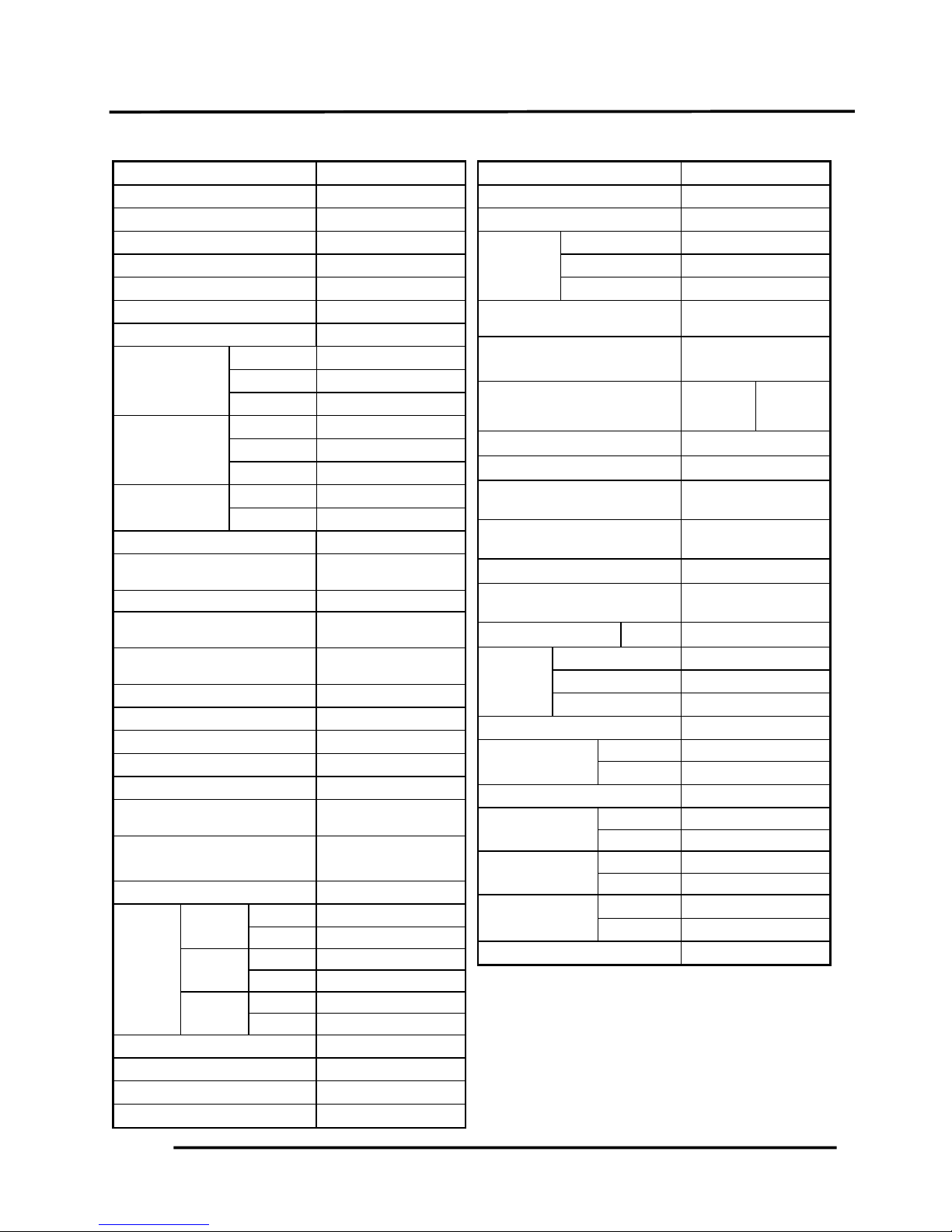
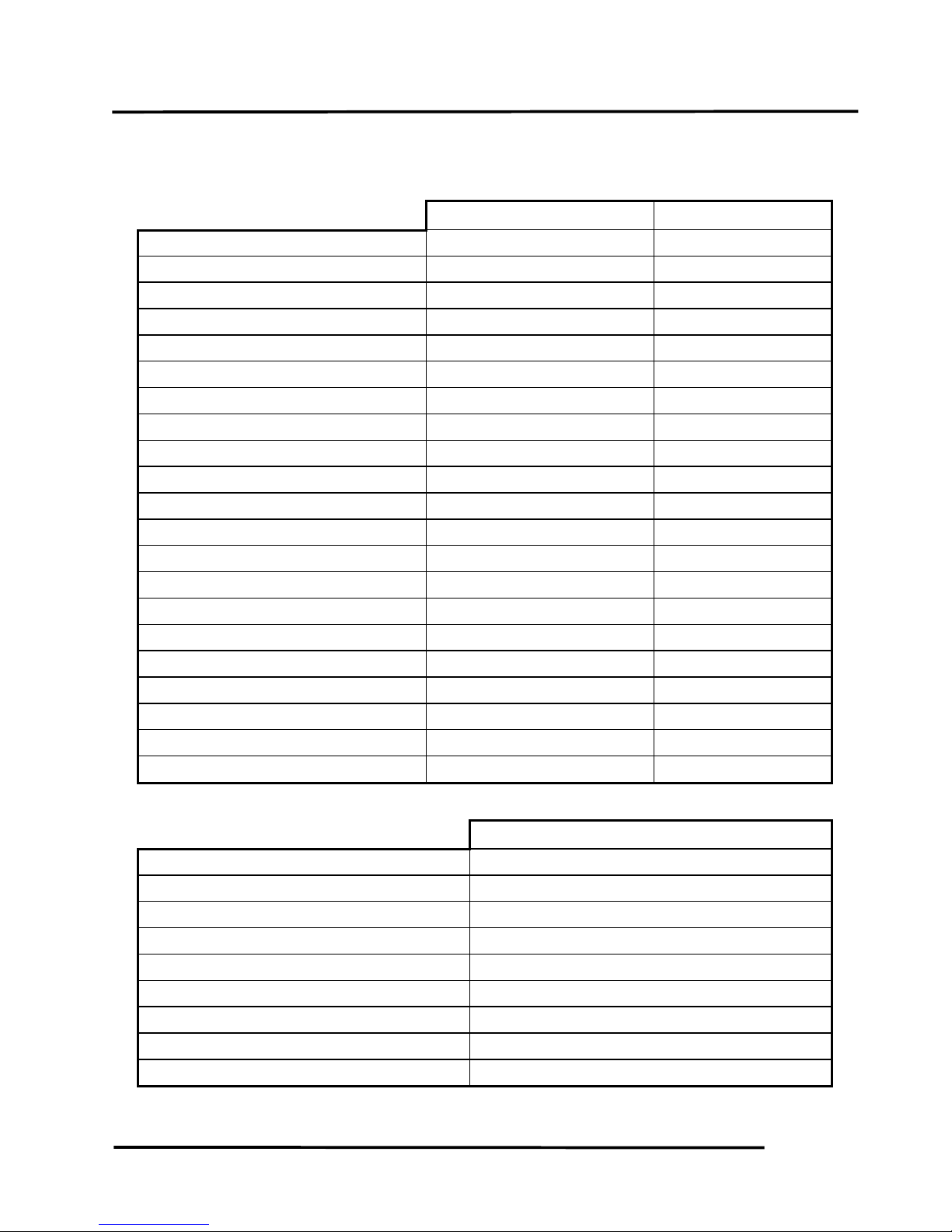
SPECIFICATIONS
Name & Model SF10JA(LDA5)
Overall length (mm) 2045
Overall width (mm) 760
Overall height (mm) 1360
Wheel base (mm) 1435
Engine type Air cooled 2-stroke
Fuel Used 92# nonleaded gasoline
Displacement (cc) 49.4 cc
Front wheel
50
Net weight (kg) Rear wheel
70
Total
120
Front wheel
91
Gross weight(kg) Rear wheel
173
Total
264
Front wheel
120/70-12
Tires
Rear wheel
130/70-12
Ground clearance (mm) 140
Braking distance (m)
(Initial speed Km/h)
4.4m (30km/h)
Min. turning radius (mm)R/L 2250/2200
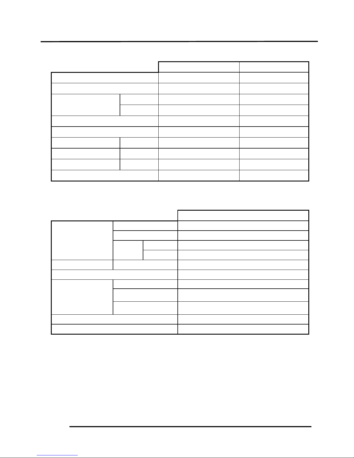
Starting system
Starting motor &
kick starter
Fuel type
Gasoline, 2-stroke
motor oil
Cylinder arrangement Single cylinder, flat
Combustion chamber type Semi-sphere
Valve arrangement Reed valve & piston
Bore x stroke (mm) 39 x 41.4
Compression ratio 7.2:1 0.2
Compression pressure
(kg/cm² rpm)
11.8kg/cm² 2
Max. output (ps/r/min)
Speed limit/No limit
3.5/7000
4.0/7000
Max. torque (kg m/rpm) 0.4/6000 kg m/rpm
Open
Automatic controlled
Intake
Close Automatic controlled
Port Open !
timing
Exhaust
Close !
Open !
Scaveng
e
Close !
Idle speed (rpm)
1850 100
Lubrication type Separate type
Oil pump type
Plunger type
Oil filter type
Full-flow filtration
Lubrication oil capacity (liter) 1.3
Air cleaner type & No. Wet, single
Fuel capacity (liter) 9.5
Type Plunger type
Carburetor Piston dia. (mm)
!
Venturi dia. (mm) 14
Ignition system type
CDI electromagnetic
Ignition
Ignition timing F mark
13.5" 1"BTDC/2000
rpm
Spark
plug
NGK
BR8HSA
Spark plug gap (mm) 0.6Д0.7
Battery capacity 12V3AH
Power to transmission gear
Power-transmission
gear-clutch
Reduction ratio of power to
transmission
!
Clutch type Dry multi-disc clutch
Transmission gear operation
type
Automatic centrifugal
type
Transmission ratio 1 speed !
Reduction Type Two-stage reduction
gear 1st reduction ratio
3.1~1.4
2nd reduction ratio
12.48
Transmission gear type Non-stage
Tirepressure
Front wheel 1.75 kg/cm²
(kg/cm²)
Rear wheel 2.0 kg/cm²
Turning angle Right & left 45"
Brake system
Front wheel hydraulic
type
Rear wheel Expanding
Suspension
Front wheel Telescope
type
Rear wheel Unit swing
Shock absorber
Front wheel Telescope
type
Rear wheel Unit swing
Frame type Pipe under bone

2. GENERAL INFORMATION
2-0
GRAND DINK 50
2
________________________________________________________________________________
________________________________________________________________________________
________________________________________________________________________________
________________________________________________________________________________
________________________________________________________________________________
GENERAL INFORMATION
____________________________________________________
____________________________
ENGINE SERIAL NUMBER/IDENTIFICATION .................................................... 2- 1
SERVICE PRECAUTIONS ................................................................................... 2- 2
SERVICE INFORMATION .................................................................................... 2- 10
TORQUE VALUES ............................................................................................... 2- 12
SPECIAL TOOLS ................................................................................................. 2- 13
LUBRICATION POINTS ....................................................................................... 2- 15
WIRING DIAGRAM............................................................................................... 2- 16
CABLE & HARNESS ROUTING........................................................................... 2- 18
TROUBLESHOOTING.......................................................................................... 2- 22
2
2. GENERAL INFORMATION
2-1
GRAND DINK 50
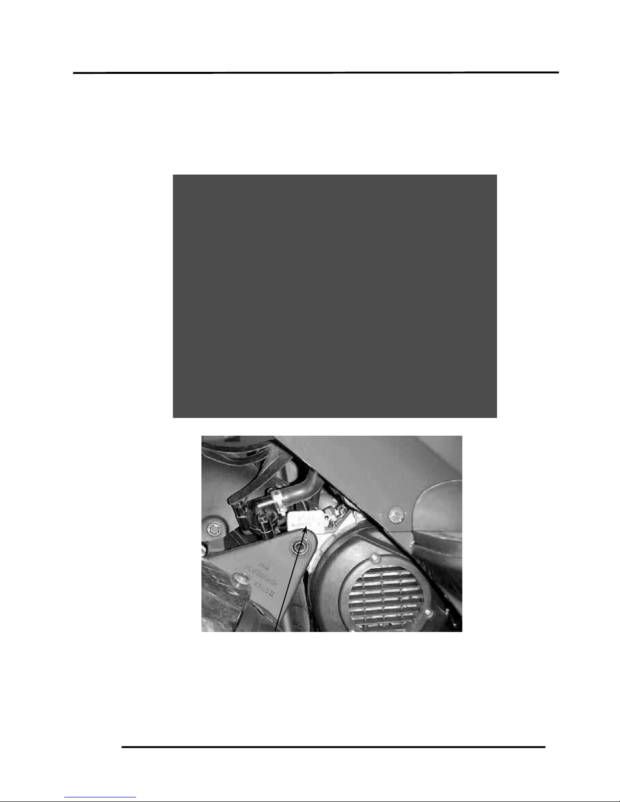
ENGINE SERIAL NUMBER/IDENTIFICATION
Location of Engine Serial Numbe
r
2. GENERAL INFORMATION
2-2
GRAND DINK 50
SERVICE PRECAUTIONS
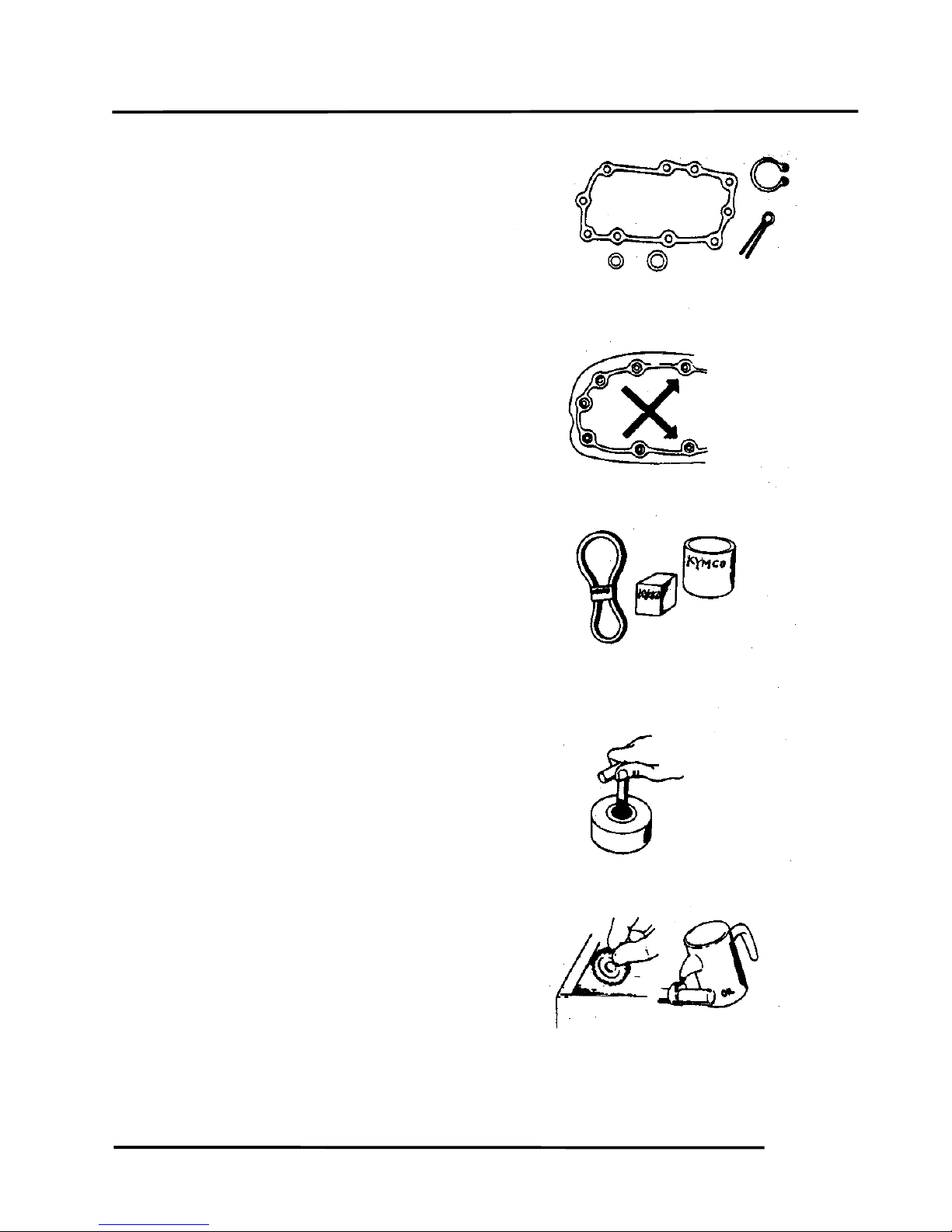
Make sure to install new gaskets, O-rings,
circlips, cotter pins, etc. when reassembling.
When tightening bolts or nuts, begin with
larger-diameter to smaller ones at several
times, and tighten to the specified torque
diagonally.
Use genuine parts and lubricants.
When servicing the motorcycle, be sure to
use special tools for removal and
installation.
After disassembly, clean removed parts.
Lubricate sliding surfaces with engine oil
before reassembly.

2. GENERAL INFORMATION
2-3
GRAND DINK 50
Apply or add designated greases and
lubricants to the specified lubrication
points.
After reassembly, check all parts for proper
tightening and operation.
When two persons work together, pay
attention to the mutual working safety.
Disconnect the battery negative (-) terminal
before operation.
When using a spanner or other tools, make
sure not to damage the motorcycle surface.
After operation, check all connecting points,
fasteners, and lines for proper connection
and installation.
When connecting the battery, the positive
(+) terminal must be connected first.
After connection, apply grease to the
battery terminals.
Terminal caps shall be installed securely.
2. GENERAL INFORMATION
2-4
GRAND DINK 50
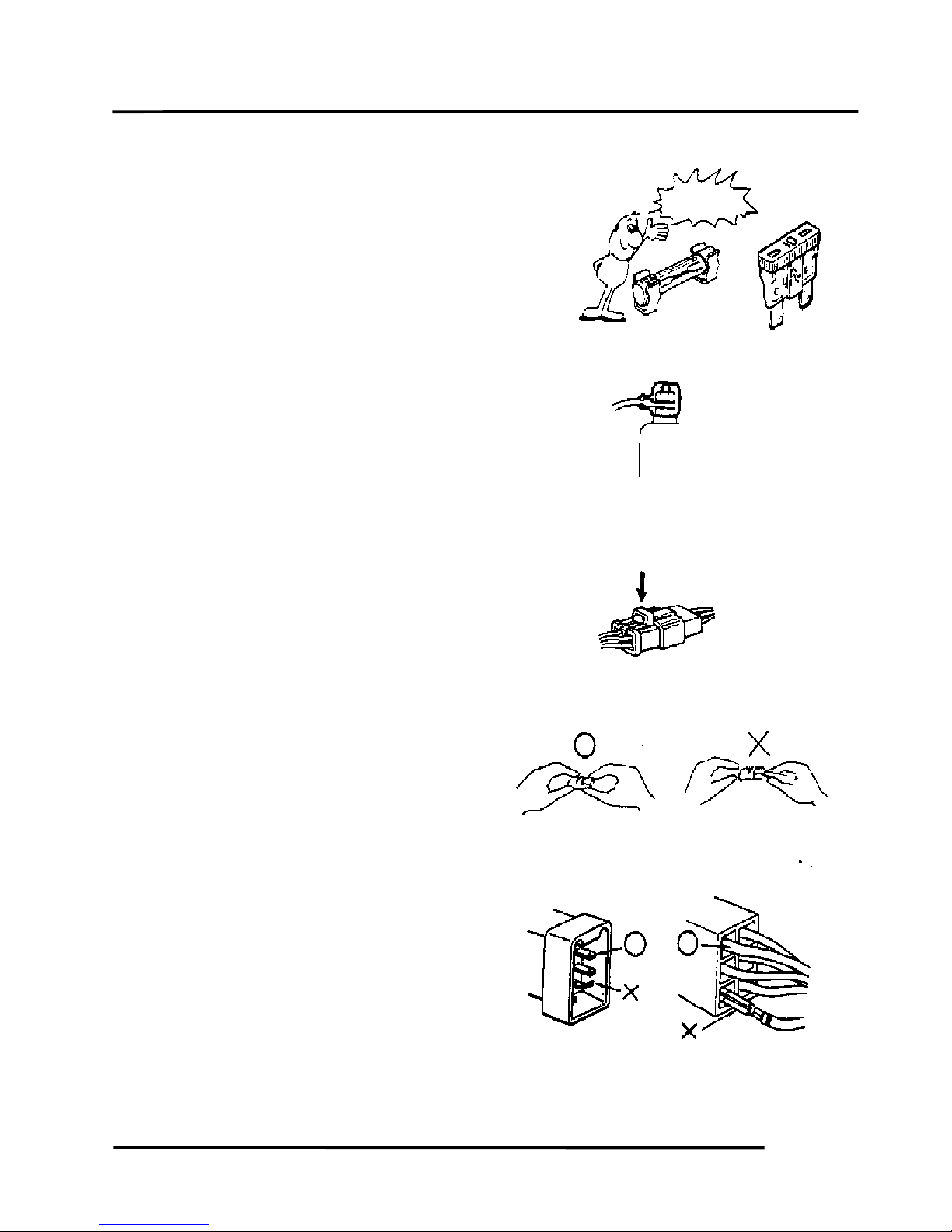
If the fuse is burned out, find the cause and
repair it. Replace it with a new one
according to the specified capacity.
After operation, terminal caps shall be
installed securely.
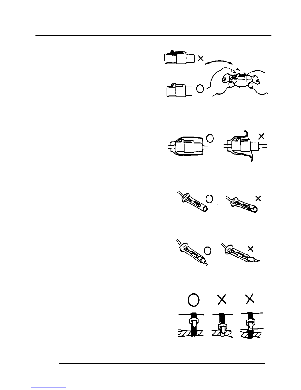
When taking out the connector, the lock on
the connector shall be released before
operation.
Hold the connector body when connecting
or disconnecting it.
Do not pull the connector wire.
Check if any connector terminal is bending,
protruding or loose.
Confirm
Capacity
2. GENERAL INFORMATION
2-5
GRAND DINK 50
The connector shall be inserted
completely.
If the double connector has a lock, lock
it at the correct position.
Check if there is any loose wire.
Before connecting a terminal, check for
damaged terminal cover or loose
negative terminal.
Check the double connector cover for
proper coverage and installation.
Insert the terminal completely.
Check the terminal cover for proper
coverage.
Do not make the terminal cover opening
face up.
Secure wire harnesses to the frame with
their respective wire bands at the
designated locations.
Tighten the bands so that only the
insulated surfaces contact the wire
harnesses.
Snapping!
2. GENERAL INFORMATION
2-6
GRAND DINK 50
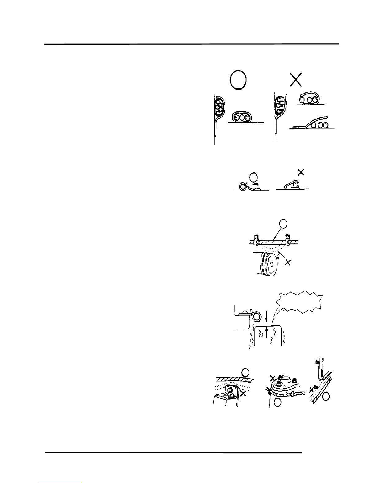
After clamping, check each wire to make
sure it is secure.
Do not squeeze wires against the weld or
its clamp.
After clamping, check each harness to
make sure that it is not interfering with any
moving or sliding parts.
When fixing the wire harnesses, do not
make it contact the parts which will
generate high heat.
Route wire harnesses to avoid sharp edges
or corners. Avoid the projected ends of
bolts and screws.
Route wire harnesses passing through the
side of bolts and screws. Avoid the
projected ends of bolts and screws.
No Contact !
2. GENERAL INFORMATION
2-7
GRAND DINK 50
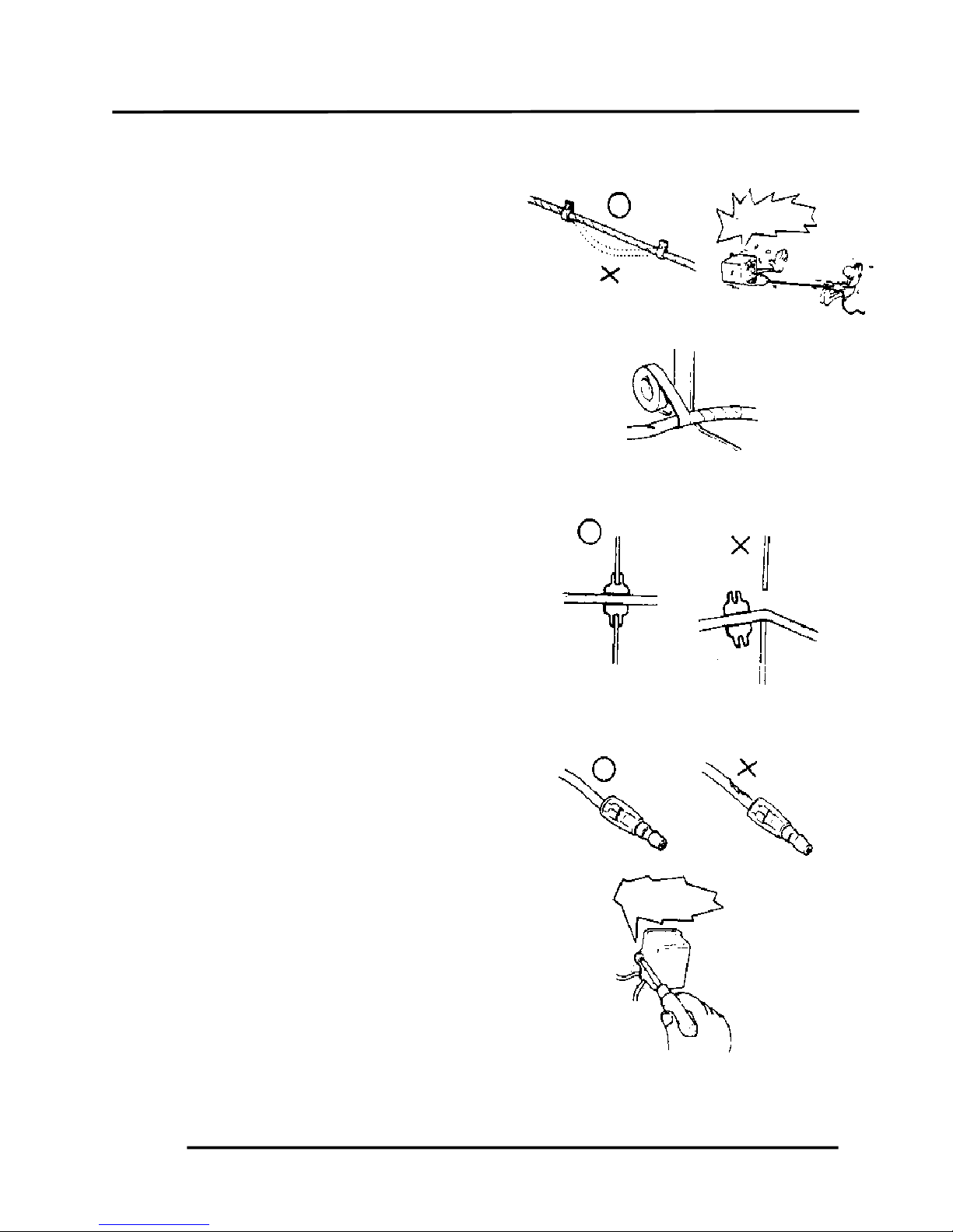
Route harnesses so they are neither
pulled tight nor have excessive slack.
Protect wires and harnesses with electrical
tape or tube if they contact a sharp edge or
corner.
When rubber protecting cover is used to
protect the wire harnesses, it shall be
installed securely.
Do not break the sheath of wire.
If a wire or harness is with a broken sheath,
repair by wrapping it with protective tape or
replace it.
When installing other parts, do not press or
squeeze the wires.
Do not pull
too tight!
Do not press o
r
squeeze the wire.
2. GENERAL INFORMATION
2-8
GRAND DINK 50
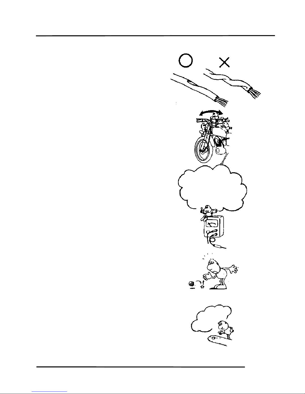
After routing, check that the wire harnesses
are not twisted or kinked.
Wire harnesses routed along with
handlebar should not be pulled tight, have
excessive slack or interfere with adjacent
or surrounding parts in all steering
positions.
When a testing device is used, make sure
to understand the operating methods
thoroughly and operate according to the
operating instructions.
Be careful not to drop any parts.
When rust is found on a terminal, remove
the rust with sand paper or equivalent
before connecting.
Do you understand
the instrument? Is
the instrument set
correctly?
Remove Rust !
2. GENERAL INFORMATION
2-9
GRAND DINK 50
Symbols:
The following symbols represent the
servicing methods and cautions included in
this service manual.
: Apply engine oil to the
specified points. (Use
designated engine oil for
lubrication.)
: Apply grease for lubrication.
: Use special tool.
: Caution
: Warning
Engine Oil
Grease
Special
• •
2. GENERAL INFORMATION
2-10
GRAND DINK 50
SERVICE INFORMATION
ENGINE
Standard (mm) Service Limit (mm)
Item
GRAND DINK 50 GRANK DINK 50
Cylinder head warpage
0.10
Piston O.D.(5mm from bottom of piston skirt)
38.970ɴ38.955 38.90
Cylinder-to- piston clearance
0.10
Piston pin hole I.D.
12.002ɴ12.008 12.03
Piston pin O.D.
11.994ɴ12.0 11.98
Piston-to-piston pin clearance
! !
Piston ring end gap (top/second)
0.10ɴ0.25 0.40
Connecting rod small end I.D.
17.005ɴ17.017 17.03
Cylinder bore
39.0ɴ39.025 39.05
Drive belt width
18 17
Drive pulley collar O.D.
20.01ɴ20.025 !
Movable drive face ID.
20.035ɴ20.085 19.97
Weight roller O.D.
13.0 12.4
Clutch outer I.D.
107ɴ107.2 107.5
Driven face spring free length
87.9 82.6
Driven face O.D.
! !
Movable driven face I.D.
! !
Connecting rod big end side clearance
! !
Connecting rod big end radial clearance
! !
Crankshaft runout A/B
!
CARBURETOR
GRANK DINK 50
Venturi dia. 14mm
Identification number PB
Float level 8.6mm
Main jet #75
Slow jet #35
Air screw opening 1¼ " ½
Idle speed 1850"100rpm
Throttle grip free play 2ɴ6mm
Jet needle clip notch 1st notch
2. GENERAL INFORMATION
2-11
FRAME
Standard (mm) Service Limit (mm)
Item GRANK DINK 50 GRANK DINK 50
Axle shaft runout 0.2
Radial
Front wheel rim runout
Axial
Front shock absorber spring free length 200.0 182.8
Rear wheel rim runout 2.0
Brake drum I.D. Front/rear 110 111
Brake lining thickness Front/rear 5.7/4.0 2.0/2.0
Brake disk runout Front/rear 0.30
Rear shock absorber spring free length 235.7 218.7
ELECTRICAL EQUIPMENT
GRANK DINK 50
Capacity 12V3AH
Voltage 13.0ɴ13.2V
Charging Standard 0.4A/5H
Battery
current Quick 4A/0.5H
Spark plug (NGK) BR8HSA
Spark plug gap 0.6ɴ0.7mm
Primary coil 0.153ɴ0.187#
Secondary coil
(with plug cap)
6.99ɴ10.21K#
Ignition coil resistance
Secondary coil
(without plug cap)
3.24ɴ3.96K#
Pulser coil resistance (20ʚ) 80ɴ160#
Ignition timing 13$"1$BTDC/2000rpm
2. GENERAL INFORMATION
2-12
GRAND DINK 50
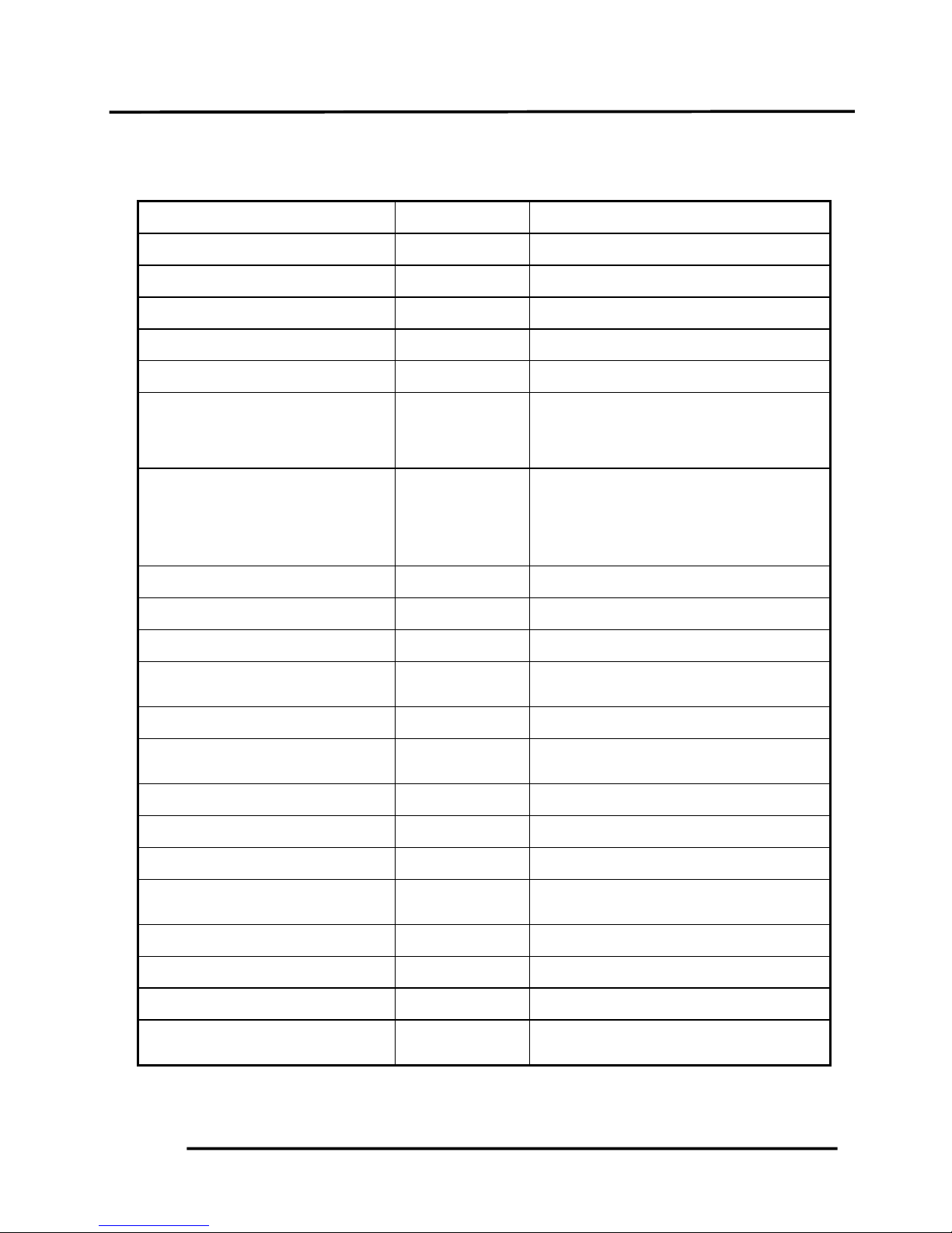
TORQUE VALUES
ENGINE
Item Thread dia. (mm) Torque (kg-m) Remarks
Cylinder head bolt
Clutch drive plate nut
Clutch outer nut
Drive face nut
Oil check bolt
Engine mounting bolt
Engine hanger bracket bolt
Exhaust muffler joint lock nut
Exhaust muffler lock bolt
Spark plug
BF7x115
10
NH10
NH12
10
BF10x95
BF10x50
NC6mm
BF8x35
1.5ɴ1.7
3.5ɴ4.0
3.5ɴ4.5
5.0ɴ6.0
1.0ɴ1.5
4.5ɴ5.5
3.5ɴ4.5
1.0ɴ1.4
3.0ɴ3.6
1.1ɴ1.7
(cold)
(cold)
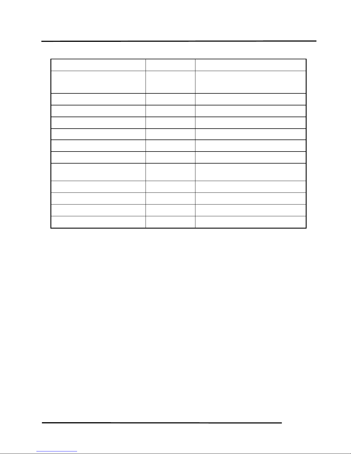
FRAME
Item Thread dia. (mm) Torque (kg-m) Remarks
Handlebar lock nut
Steering stem lock nut
Steering top cone race
Front axle nut
Rear axle nut
Rear brake arm bolt
Front shock absorber:
upper mount bolt
lower mount bolt
hex bolt
Front damper nut
Front pivot arm bolt
Rear shock absorber:
upper mount bolt
lower mount bolt
lower joint nut
10
25.4
25.4
12
16
8
8
10
8
8
4.5ɴ5.0
8.0ɴ12.0
0.5ɴ1.3
5.0ɴ7.0
11.0ɴ13.0
3.3
3.3
1.5ɴ3.0
1.5ɴ3.0
3.5ɴ4.5
2.4ɴ3.0
1.5ɴ2.5
Flange bolt/U-nut
Flange U-nut
Flange U-nut
Flange nut
Flange bolt/U-nut
Cross head
Apply locking agent
Flange screw/U-nut
Flange nut
Torque specifications listed above are for important fasteners. Others should be tightened to
standard torque values below.
STANDARD TORQUE VALUES SH bolt: 8mm Flange 6mm bolt
Item Torque (kg-m) Item Torque (kg-m)
5mm bolt, nut
6mm bolt, nut
8mm bolt, nut
10mm bolt, nut
12mm bolt, nut
0.45ɴ0.6
0.8ɴ1.2
1.8ɴ2.5
3.0ɴ4.0
5.0ɴ6.0
5mm screw
6mm screw, SH bolt
6mm flange bolt, nut
8mm flange bolt, nut
10mm flange bolt, nut
0.35ɴ0.5
0.7ɴ1.1
1.0ɴ1.4
2.4ɴ3.0
3.5ɴ4.5
2. GENERAL INFORMATION
2-13
SPECIAL TOOLS
Tool Name Tool No. Remarks
Universal bearing puller Crankshaft bearing removal
Lock nut wrench, 39mm Drive pulley disassembly/assembly
Lock nut socket wrench Top cone race holding
Lock nut wrench, Stem lock nut tightening
Crankcase puller Crankcase disassembly
Bearing remover set, 12mm
(Spindle assy, 15mm)
(Remover weight)
Drive shaft bearing removal/installation
Bearing remover set, 15mm
(Spindle assy, 15mm)
(Remover head, 15mm)
(Remover shaft, 15mm)
Drive shaft bearing removal/installation
Bearing outer driver, 28x30mm Bearing installation
Bearing remover Driven pulley outer bearing installation
Clutch spring compressor Driven pulley disassembly/assembly
Crankcase assembly collar
Driven shaft, crankshaft & crankcase
assembly
Crankcase assembly tool Crankshaft & crankcase assembly
Rear shock absorber remover
Front shock absorber disassembly/
assembly
Ball race remover Steering stem bearing races
Rear shock absorber compressor Rear shock absorber disassembly/assembly
Float level gauge Carburetor fuel level check
Lock nut socket wrench, 32mm
One-way clutch lock nut removal/
installation
Universal holder Flywheel holding
Flywheel puller Flywheel removal
Pilot, 12mm Drive shaft bearing installation
Bearing outer driver, 32x35mm
Drive shaft bearing installation
Final shaft bearing installation
2. GENERAL INFORMATION
2-14
GRAND DINK 50
Tool Name Tool No. Remarks
Bearing outer driver, 37x40mm
Drive shaft bearing installation Final shaft
bearing installation Crankshaft bearing
installation
Outer driver, 24x26mm Driven pulley bearing installation
Pilot, 10mm Front wheel bearing installation
Bearing driver pilot, 17mm Drive shaft bearing installation
Snap ring pliers (close) Circlip removal/installation
Bearing outer driver, 42x47mm Crankshaft bearing installation
Pilot, 20mm Crankshaft bearing installation
Bearing outer driver handle A
Bearing installation
Drive in ball race
Bearing puller head, 10mm Front wheel bearing removal
Universal bearing puller Crankshaft bearing removal
Bearing puller Front wheel bearing removal
Pressure tester set Cylinder compression gauge
2. GENERAL INFORMATION
2-15
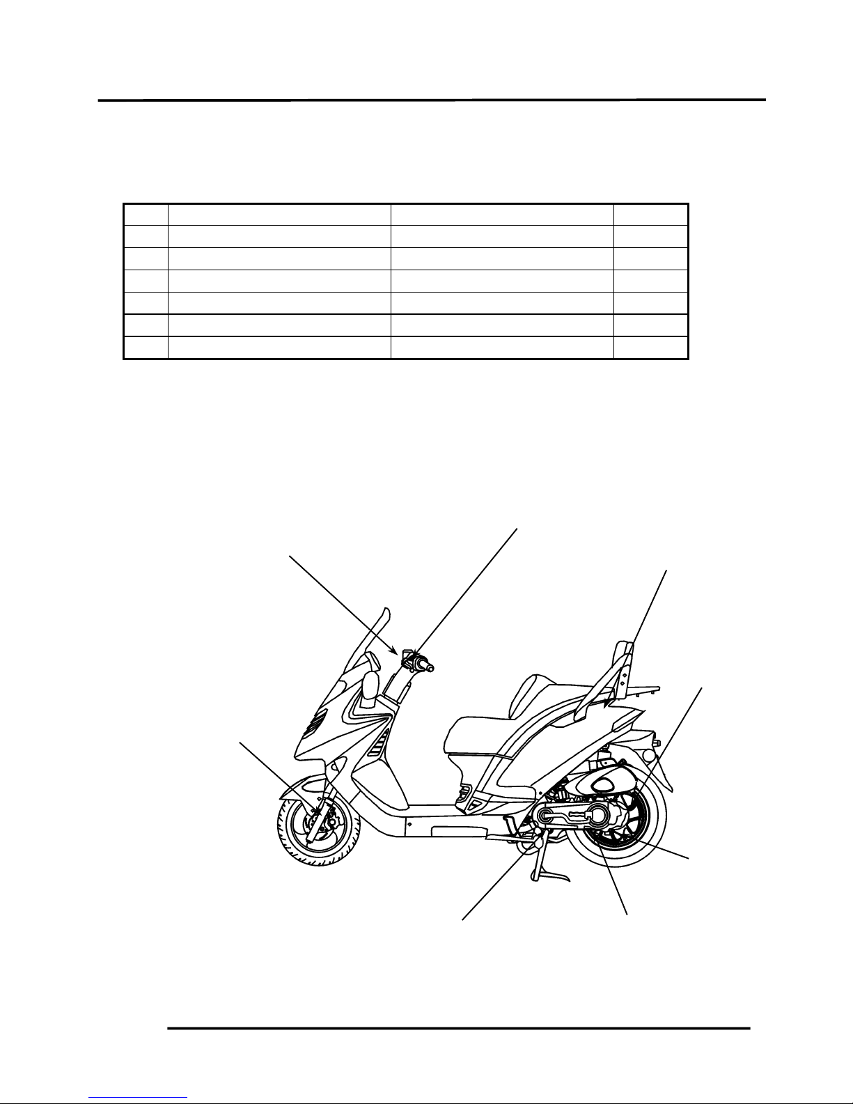
LUBRICATION POINTS
ENGINE
NO. Lubrication Points Lubricant Remarks
1 Crankcase sliding & movable JASO-FC or API-TC
2 Cylinder movable parts
3 Transmission gear (final gear) SAE-90#
4 Kick starter spindle bushing Grease
5 Drive pulley movable parts Grease
6 Starter pinion movable parts Grease
FRAME
Apply clean engine oil or grease to cables and movable parts not specified. This will avoid
abnormal noise and rise the durability of the motorcycle.
Front/Rear Brake Leve
r
Seat Lock
Rear Wheel
Bearing
Throttle Cable
Main Stand Pivot
Grease
Engine Oil
Grease
Speedometer Gear/
Brake Cam/Front
Shock Absorber
Lower Mount
Bushings/Pivot
Grease
Grease
Grease
Grease
Engine Oil
Rear Brake Cable
Brake Cam/
Anchor Pin
2. GENERAL INFORMATION
2-16
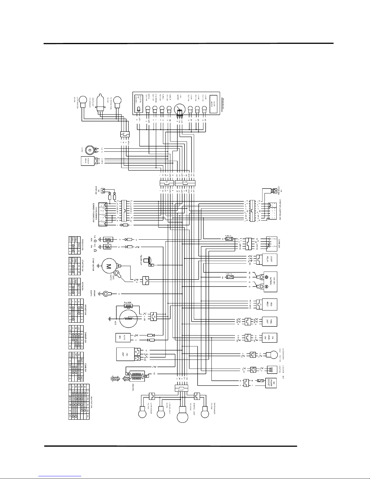
GRAND DINK 50
GRAND DINK 50 WIRING DIAGRAM
2. GENERAL INFORMATION
2-17
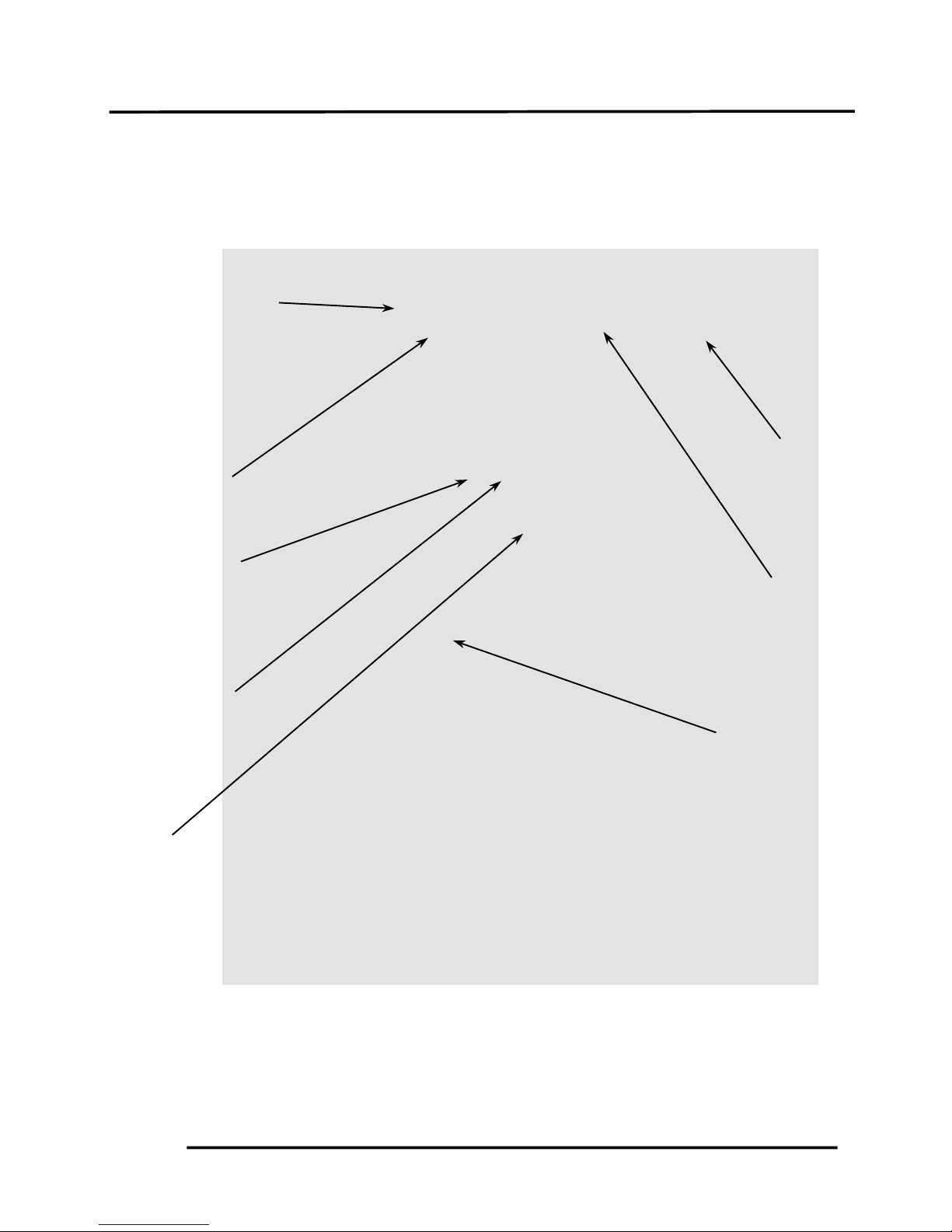
CABLE & HARNESS ROUTING
Front Brake Reservoi
r
Rear Brake Cable
Throttle Cable
Ignition Switch
Rear Stop Brake
Front Brake Fluid
Tube
Speedometer Cable
Horn

2. GENERAL INFORMATION
2-18
GRAND DINK 50
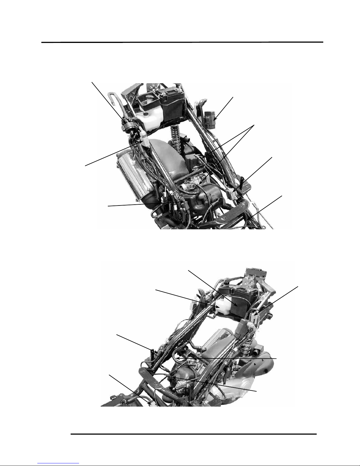
Wire Harness
Rear Brake Cable
Throttle Cable
Front Brake Fluid Tube
Speedometer Cable
Front Brake Reservoi
r
Fuel Fille
r
Fuel Tank
Breather Tube
Fuel Tank Inlet
Tube
2. GENERAL INFORMATION
2-19
Ignition Coil
Regulator/Rectifie
r
Fuel Filte
r
C.D.I. Unit
Oil Tube
Spark Plug
Resistance
Ignition Coil
A
ir Injection Control Valve
Fuel Pump
Fuel Tube
Throttle Cable
Battery
Oil Tank

2. GENERAL INFORMATION
2-20
GRAND DINK 50
Oil Tank Cap
Battery (-) Cable
Seat Cable
A
.C.G Connect
wire
A
uto Bystarte
r
Fuel Pump
Fuel Tube
Fuel Pump
Vacuum Tube
Oil Tube
Spark Plug Cap
Oil Pump
Battery (+) Cable
2. GENERAL INFORMATION
2-21
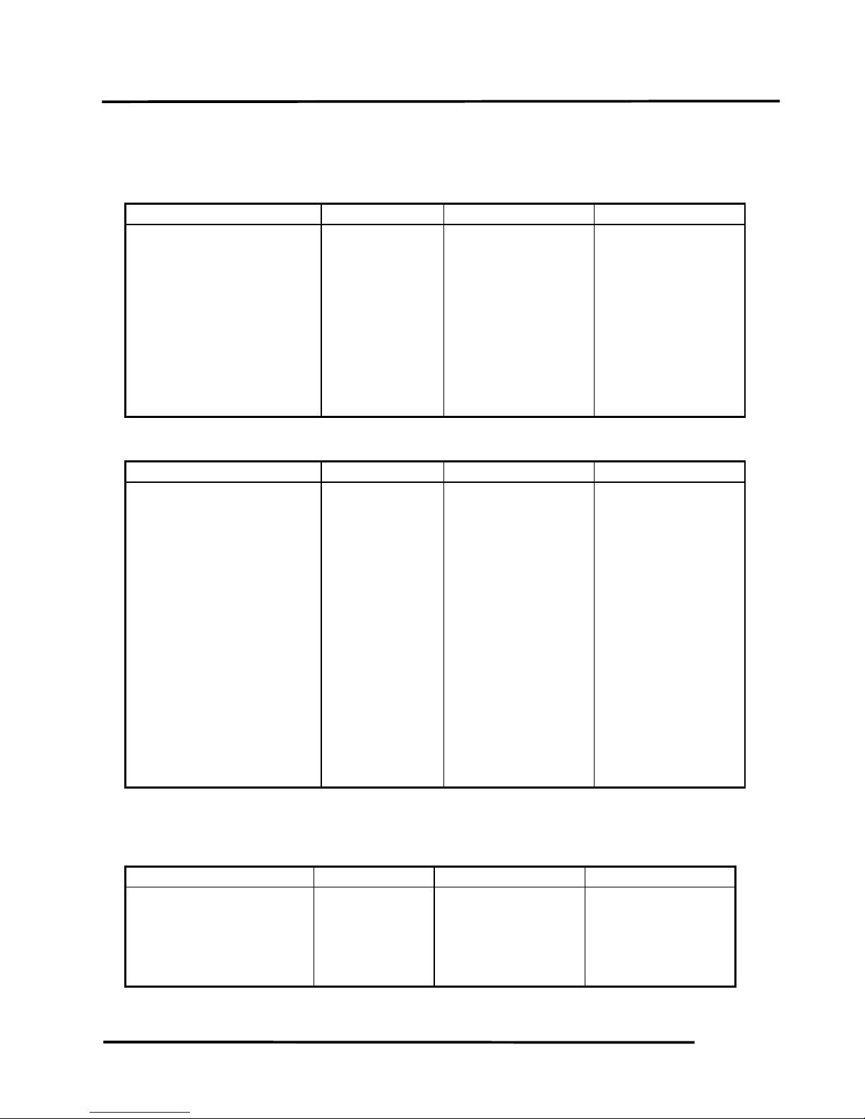
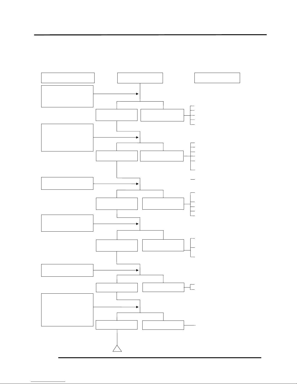
TROUBLESHOOTING
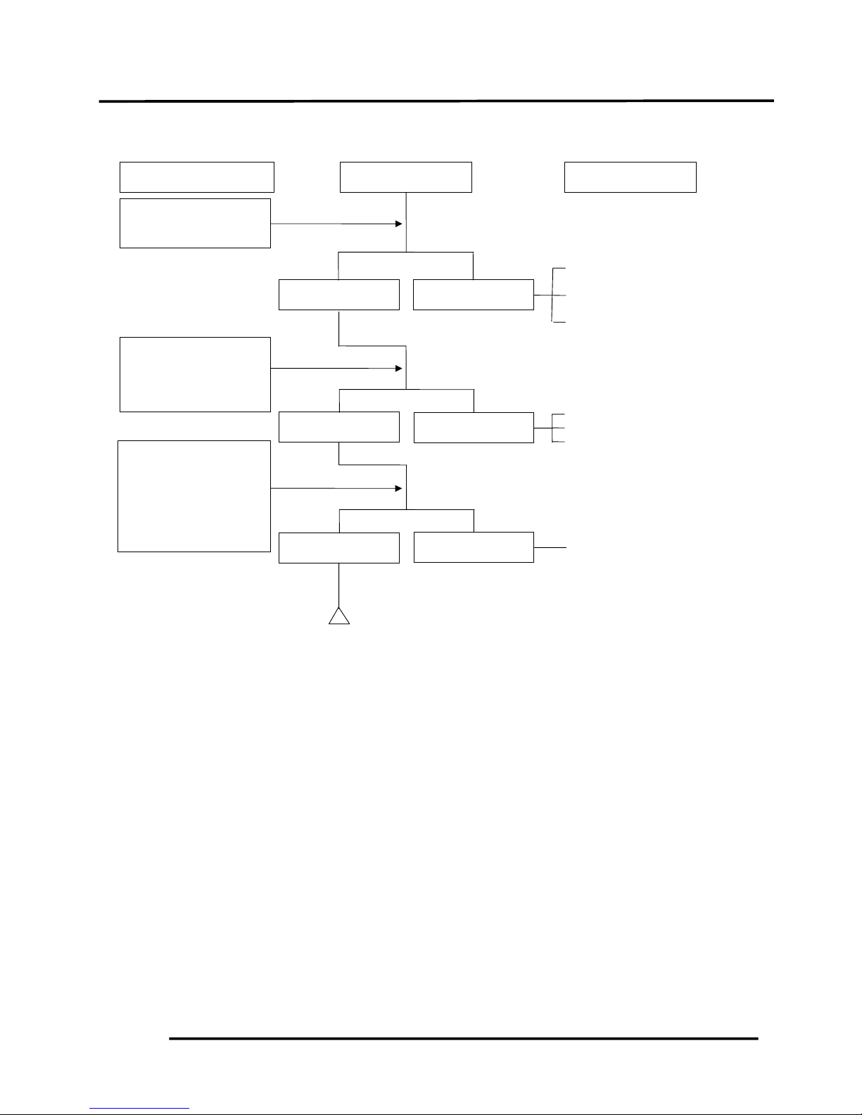
ENGINE WILL NOT START OR IS HARD TO START
! Empty fuel tank
" Clogged float valve
# Clogged charcoal canister
$ Clogged fuel filter
% Faulty auto fuel valve
! Faulty spark plug
" Fouled spark plug
# Faulty CDI unit
$ Faulty A.C. generator
% Broken or shorted ignition
coil
& Broken or shorted exciter
coil
'Faulty ignition switch
! Burned or worn cylinder
piston
" Faulty reed valve
# Blown cylinder head gasket
$ Leaking crankcase
% Faulty crankcase oil seal
! Incorrectly adjusted idle
speed
" Air leaking through intake
pipe
# Incorrect ignition timing
! Flooded carburetor
" Throttle valve excessively
open
! Faulty auto bystarter
Check if fuel reaches
carburetor by
loosening drain
screw.
Remove spark plug
and install it into
spark plug cap to test
spark by connecting it
to engine ground.
Inspection/Adjustment
Symptom
Probable Cause
Fuel reaches
carburetor
Spark jumps
Dry spark plug
Not clogged
Normal
compression
Engine does not
fire
Fuel does not
reach carburetor
Weak or no spark
Wet spark plug
Clogged
Low or no
compression
Engine fires but
does not start
Test cylinde
r
compression.
Remove spark plug
and inspect again.
Wait for 30 minutes
and then remove the
carbu-retor auto
choke circuit hose
and blow the hose
with mouth.
Start engine by
follow-ing normal
startin
g
procedure.
2. GENERAL INFORMATION
2-22
GRAND DINK 50
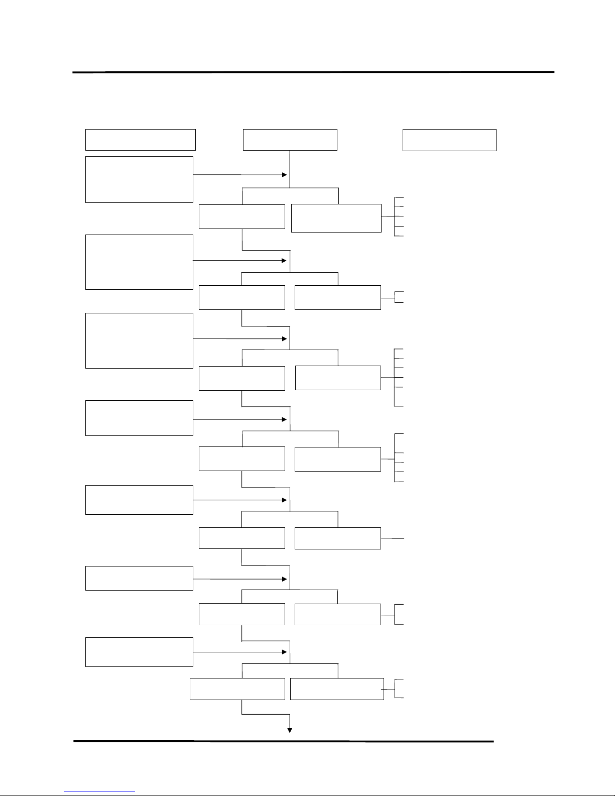
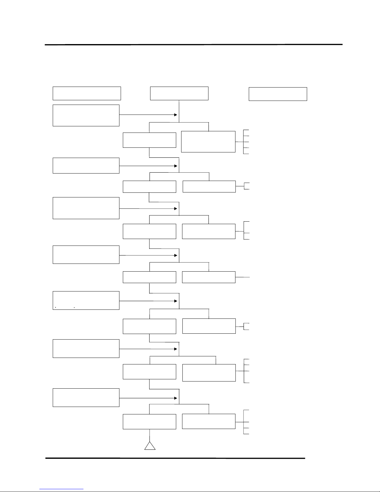
ENGINE STOPS IMMEDIATELY AFTER IT STARTS
! Empty fuel tank
" Clogged float valve
# Clogged charcoal canister
$ Clogged fuel filter
% Faulty auto fuel valve
! Fouled spark plug
" Incorrect heat range plug
! Fouled spark plug
" Faulty CDI unit
# Faulty A.C. generator
$ Faulty ignition coil
% Broken or shorted high
tension wire
& Faulty ignition switch
! Worn cylinder and piston
rings
" Blown cylinder head gasket
# Flaws in cylinder head
$ Faulty reed valve
% Seized piston
! Clogged carburetor jets
! Faulty CDI unit or A.C.
generator
" A.C.G. flywheel not aligned
! Mixture too rich (turn screw
out)
" Mixture too lean (turn
screw in)
Check if fuel reaches
carburetor by
loosening drain
screw.
Inspection/Adjustment Symptom
Probable Cause
Fuel reaches
carburetor
Good spark
Remove spark plug
and install it into
spark plug cap to test
spark by connecting it
to engine ground.
Correct timing
Correctly adjusted
Plug not fouled o
r
discolored
Normal
compression
Not Clogged
Fuel does not
reach carburetor
Weak or inter-
mittent spark
Incorrect timing
Incorrectly adjusted
Plug fouled o
r
discolored
Abnormal
compression
Clogged
Test cylinde
r
compression (using a
compression gauge).
Check carburetor fo
r
clogging.
Check ignition timing.
Check carburetor ai
r
screw adjustment.
Remove spark plug
and install it into
spark plug cap to test
spark by connecting it
to engine ground.
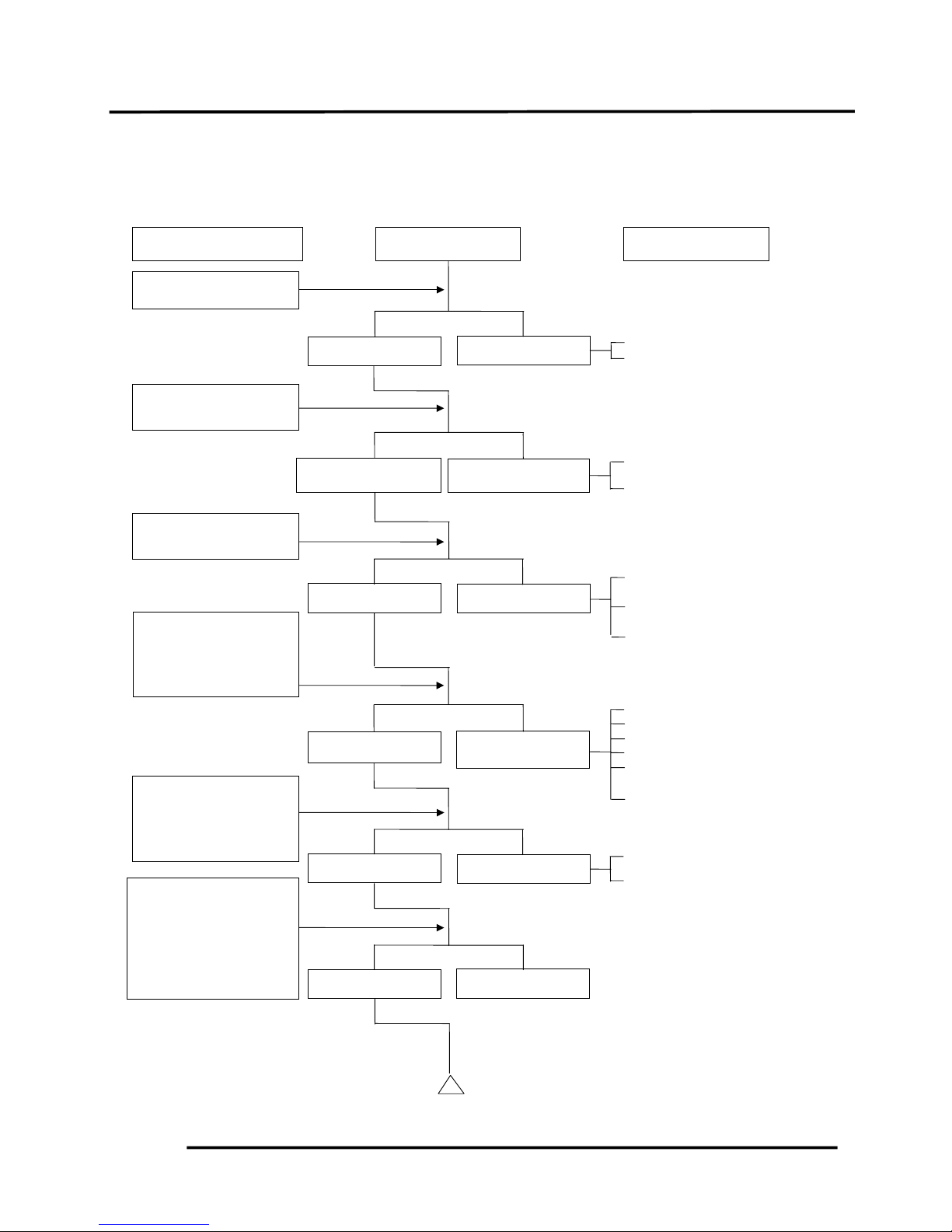
2. GENERAL INFORMATION
2-23
! Carburetor not securely
tightened
" Faulty intake manifold
gasket
# Deformed or broken
carburetor O-ring
! Broken cable
" Dirty auto bystarter
# Faulty auto bystarter
! Faulty auto bystarter
Inspection/Adjustment
Symptom
Probable Cause
No air leak
Not clogged
Clogged
Air leaks
Clogged
Not Clogged
Check carbureto
r
gasket for air leaks.
Connect auto
bystarter wire to
battery. Wait for 5
minutes, then connect
a hose to fuel
enriching circuit and
then blow the hose
Remove auto
bystarter connecting
wire and check if
bypass fuel line is
clo
gg
ed.
2. GENERAL INFORMATION
2-24
GRAND DINK 50
ENGINE LACKS POWER
! Clogged air cleaner
" Clogged fuel filter
# Clogged exhaust muffler
$ Faulty auto bystarter
% Faulty charcoal canister
! Faulty CDI unit
" Faulty A.C. generator
! Worn cylinder and piston
rings
" Blown cylinder head gasket
# Faulty reed valve
! Clogged carburetor jets
! Fouled spark plug
" Incorrect heat range plug
! Mixture too lean
" Poor quality fuel
# Excessive carbon build-up
in combustion chamber
$ Ignition timing too early
! Excessive carbon build-up
in combustion chamber
" Poor quality fuel
# Clutch slipping
$ Mixture too lean
Inspection/Adjustment Symptom
Probable Cause
Engine speed
increases
Engine
overheats
Correct timing
Engine does not
knock
Plug not fouled o
r
discolored
Normal
compression
Not Clogged
Engine speed
does not increase
sufficiently
Engine does not
overheats
Incorrect timing
Engine knocks
Plug fouled o
r
discolored
Abnormal
compression
Clogged
Start engine and
accelerate lightly for
observation.
Check ignition timing
(using a timing light).
Rapidly accelerate o
r
run at high speed
Test cylinde
r
compression (using a
compression gauge)
Check carburetor fo
r
clogging
Remove spark plug
and
Check if engine
overheats
2. GENERAL INFORMATION
2-25
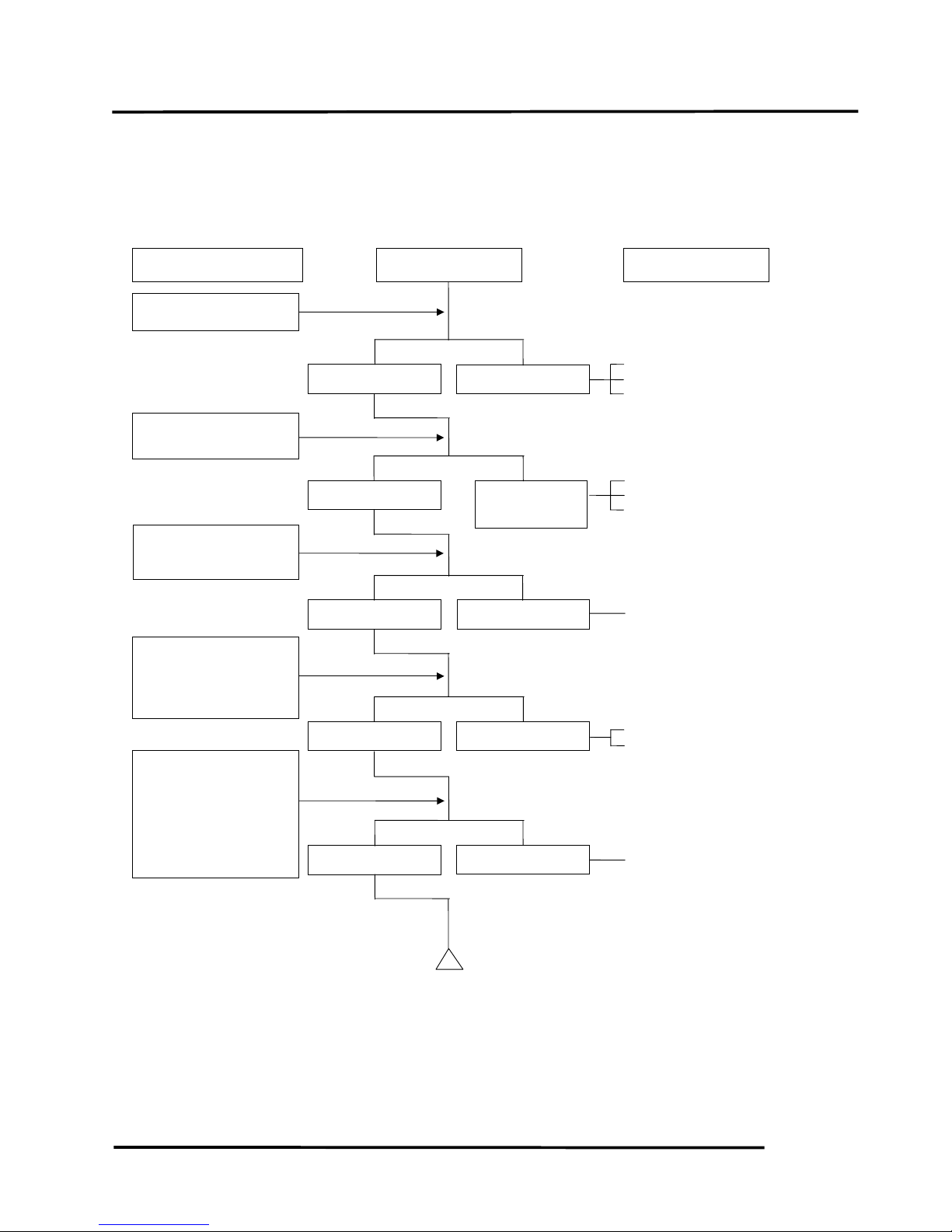
POOR PERFORMANCE (ESPECIALLY AT IDLE AND LOW SPEEDS)
! Faulty CDI unit
" Faulty A.C. generator
! Mixture too rich (turn screw
out)
" Mixture too lean (turn
screw in)
! Carburetor not securely
tightened
" Faulty intake manifold
gasket
# Deformed carburetor O-
ring
! Faulty or fouled spark plug
" Faulty CDI unit
# Faulty A.C. generator
$ Faulty ignition coil
% Broken or shorted high
tension wire
& Faulty ignition switch
! Broken auto bystarter wire
" Faulty auto bystarter
Inspection/Adjustment Symptom Probable Cause
Clogged
Not clogged
Remove spark plug
and install it into
spark plug cap to test
spark by connecting it
to engine ground.
Check ignition timing.
Connect auto bystarte
r
wire to battery. Wait
for 5 minutes, then
connect a hose to fuel
enriching circuit and
then blow the hose
with mouth.
Remove auto
bystarter connecting
wire and check if
bypass fuel line is
clogged.
Check carbureto
r
gasket for air leaks.
Check carburetor ai
r
screw adjustment.
Correct timing
Incorrect timing
Correctly adjusted
Incorrectly adjusted
No air leak
A
ir leaks
Good spark
Weak or inter-
mittent spark
Not clogged
Clogged
2. GENERAL INFORMATION
2-26
GRAND DINK 50
POOR PERFORMANCE (AT HIGH SPEED)
! Faulty CDI unit
" Loose A.C.G. stator
# Faulty A.C. generator
! Empty fuel tank
" Clogged fuel tube or filter
# Clogged charcoal canister
! Clean and unclog
! Broken auto bystarter wire
" Faulty auto bystarter
! Faulty auto bystarter
Inspection/Adjustment Symptom Probable Cause
Clogged
Not clogged
Check ignition timing.
Connect auto
bystarter wire to
battery. Wait for 5
minutes, then
connect a hose to fuel
enriching circuit and
then blow the hose
with mouth.
Remove auto
bystarter connecting
wire and check if
bypass fuel line is
clo
gg
ed.
Check carburetor jets
for clogging.
Check auto fuel valve
for fuel supply.
Correct timing
Incorrect timing
Fuel flows freely
Fuel flow
restricted
Not clogged
Clogged
Not clogged
Clogged
 Loading...