

Page 1
DOWNTOWN 200i
By KWANG YANG Motor Co., Ltd.
1st Edition, Dec 2009
All rights reserved. Any reproduction or
unauthorized use without the written
permission of KWANG YANG Motor Co., Ltd.
is expressly prohibited.
T300-SK40AA-A1
Page 2
DOWNTOWN 200i
PREFACE
This Service Manual describes the
technical features and servicing
procedures for the KYMCO
Downtown
200
i.
Section 1 contains the precautions for
all operations stated in this manual.
Read them carefully before any
operation is started.
Section 2 is the removal/installation
procedures for the frame covers which
are subject to removal/installation
frequency during maintenance and
servicing operations.
Section 3 describes the inspection/
adjustment procedures, safety rules
and service information for each part,
starting from periodic maintenance.
Sections 5 to 12 give instructions for
disassembly, assembly and
adjustment of engine parts. Section 13
is the AFI system. Section 14 to 15 is
the removal/ installation of chassis.
Section 16 to 19 states the testing and
measuring methods of electrical
equipment.
Most sections start with an assembly
or system illustration and
troubleshooting for the section. The
subsequent pages give detailed
procedures for the section.
KWANG YANG MOTOR CO., LTD.
QUALITY TECHNOLOGY DEPT.
EDUCATION SECTION
TABLE OF CONTENTS
GENERAL INFORMATION
1
EXHAUST MUFFLER/FRAME
COVERS
2
INSPECTION/ADJUSTMENT
3
LUBRICATION SYSTEM
4
ENGINE REMOVAL/INSTALLATION
5
CYLINDER HEAD/VALVES
6
CYLINDER/PISTON
7
DRIVE AND DRIVEN PULLEYS/VBELT
8
FINAL REDUCTION
9
A.C. GENERATOR/STARTER
CLUTCH
10
CRANKCASE/CRANKSHAFT
11
COOLING SYSTEM
12
FUEL INJECTION SYSTEM
13
STEERING HANDLEBAR/FRONT
WHEEL/FRONT BRAKE/FRONT
SHOCK ABSORBER/FRONT FORK
14
REAR BRAKE/REAR FORK/REAR
WHEEL/REAR SHOCK ABSORBER`
15
BATTERY/CHARGING SYSTEM
16
IGNITION SYSTEM
17
STARTING SYSTEM
18
LIGHTS SWITCHES / FUEL PUMP
19
The information and contents
included in this manual may be
different from the motorcycle in case
specifications are changed.
CHASSIS
ELE
C
TRI
C
AL
EQUIPMENT
ENGINE
Page 3

1. GENERAL INFORMATION
1-0
DOWNTOWN 200i
1
________________________________________________________________________________
________________________________________________________________________________
________________________________________________________________________________
________________________________________________________________________________
________________________________________________________________________________
GENERAL INFORMATION
________________________________________________________________________________
SERIAL NUMBER------------------------------------------------------------------------------------1-1
SPECIFICATION -------------------------------------------------------------------------------------1-2
SERVICE PRECAUTIONS-------------------------------------------------------------------------1-3
TORQUE VALUES-----------------------------------------------------------------------------------1-4
SPECIAL TOOLS-------------------------------------------------------------------------------------1-6
LUBRICATION POINTS ----------------------------------------------------------------------------1-7
CABLE & HARNESS ROUTING---------------------------------------------------------------------1-8
1
Page 4
1. GENERAL INFORMATION
1-1
DOWNTOWN 200i
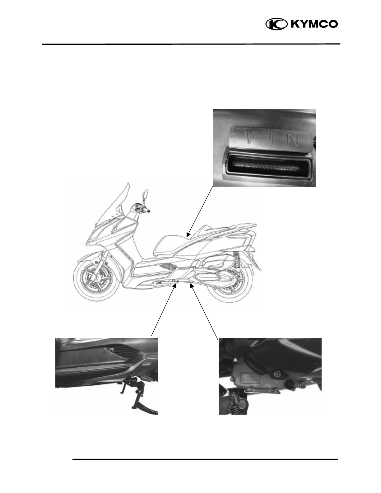
SERIAL NUMBER
Location of Frame Serial Number
(inside luggage box)
Location of Vehicle Identification
Number (VIN)
Location of Engine Serial Number
Page 5

1. GENERAL INFORMATION
1-2
DOWNTOWN 200i
SPECIFICATIONS
Name Downtown 200i
Model No. SK40AA
Overall length 2200 mm
Overall width 800 mm
Overall height 1410 mm
Wheel base 1545 mm
Engine type 4 stroke O.H.C.
Displacement 205 cc
Fuel Used 92# nonleaded
gasoline
Front wheel
70
Rear wheel
104
Total
174
Front wheel
149
Rear wheel
205
Total
354
Ground clearance (mm)
140
Braking distance (m)
7.9m / 30 km/hr
Min. turning radius (m)
2.6
Engine part
Starting system
Starting motor
Type
Gasoline 4-cycle
Cylinder arrangement Single cylinde
r
Combustion chamber type Semi-sphere
Valve arrangement O.H.C.-4V
Bore x stroke (mm) φ66 * 60
Compression ratio 10.5:1
Compression pressure
(kg/cm²)
16
Max. output (ps/rpm)Engine 20.6 /8000
Max. torque (kg-m/rpm) 2.03 / 6500
Open 5° BTDC
Close 32° BTDC
Open 34° BTDC
Close 5° BTDC
Intake
0.10
Exhaust
0.10
Idle speed (rpm)
1600±100 rpm
Cooling Type
Liquid cooling
Lubrication type
Forced pressure &
wet sump
Oil pump type Inner/outer roto
r
Oil filter type Full-flow filtration
Oil capacity 1.5ℓ
Exchanging capacity 1.3 ℓ
Fi injection system
Air cleaner type & No Paper element, wet
Fuel capacity 12.5 ℓ
Brand Keihin(LGF9)
Throttle Body
Butterfly type
Venturi diameter (mm)
32
Fuel pump pressure
3 bar
Electrical system
Ignition type
ECU
Ignition timing
4°~32°
Spark plug CR7E (NGK)
Spark plug gap 0.6~0.7mm
Battery Capacity 12V10AH
Transmission system
Clutch type
Dry multi-disc
Transmission type
CVT
Operation type Auto centrifugal
Reduction gear type
Two-stage reduction
1
st
0.81 ~ 2.57
2nd 9.54
Moving device
Tire type
Tubeless
Front wheel
120/80-14 58S
Rear wheel
150/70-13 64S
Front wheel
2.0
Rear wheel
2.25
Wheel material
Aluminium
Left 40°
Right 40°
Front Disk brake
Rear Drum brake
Damping Device
Front
Telescope
Rear Swing arm
Front 110 mm
Shock absorber
stroke
Rear 100 mm
Page 6
1. GENERAL INFORMATION
1-3
DOWNTOWN 200i
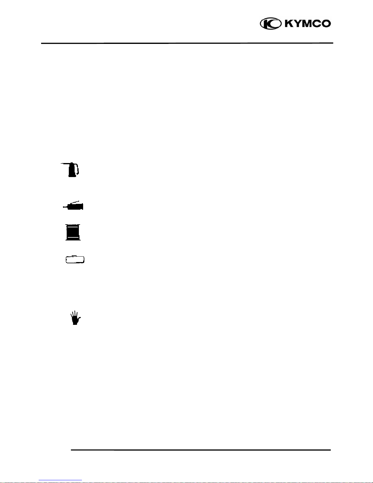
Symbols:
The following symbols represent the
servicing methods and cautions included in
this service manual.
: Apply engine oil to the
specified points. (Use
designated engine oil for
lubrication.)
: Apply grease for lubrication.
: Transmission Gear Oil (90#)
: Use special tool.
: Caution
: Warning
Special
Engine Oil
Grease
Gear Oil
*
Page 7
1. GENERAL INFORMATION
1-4
DOWNTOWN 200i
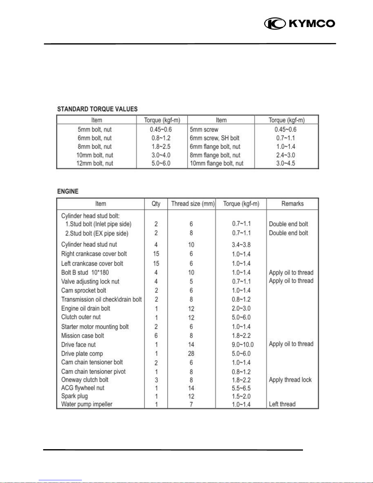
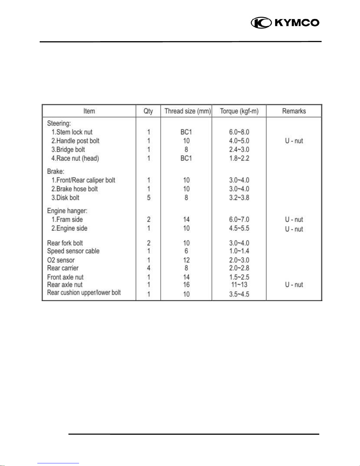
TORQUE VALUES
Page 8
1. GENERAL INFORMATION
1-5
DOWNTOWN 200i
TORQUE VALUES
FRAME
Page 9
1. GENERAL INFORMATION
Downtown 200i
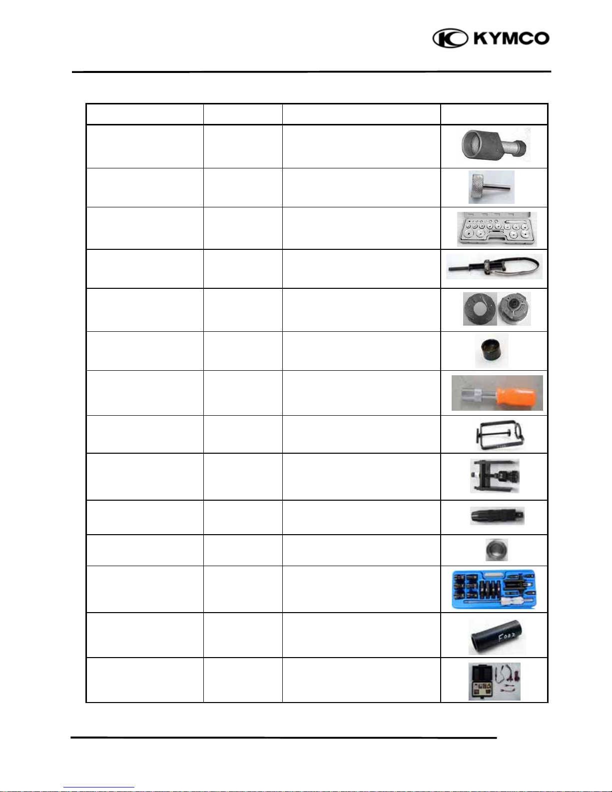
SPECIAL TOOLS
Tool Name Tool No. Performance Photo
Flywheel Puller A120E00003 A.C. generator flywheel removal
Tappet Adjuster A120E00012 Tappet adjustment
Oil Seal & Bearing
Installer
A120E00014 Oil seal & bearing installing
Flywheel Holder A120E00021 A.C. generator flywheel holding
#41 Nut & Fitting A120E00028 Clutch disassembly & assembly
Thread Protector A120E00029 Protecting the crankshaft’s
thread
Valve Cotter Installer A120E00051 Valve cotter installation
Clutch Spring
Compressor
A120E00053 Clutch disassembly & assembly
Shaft Collar Puller A120E00088 Bearing crankcase removal
Shaft Collar Driver A120E00091 Bearing crankcase removal
Shaft Collar Installer A120E00092 Bearing crankcase installation
Bearing Puller A120E00093 Bearing removal
Lock Nut Socket Wrench A120F00002 Steering stem removal or
installation
Electric Repair Kit A120F00032 Fuel injection system diagnosis
1-6
Page 10
1. GENERAL INFORMATION
1-7
DOWNTOWN 200i
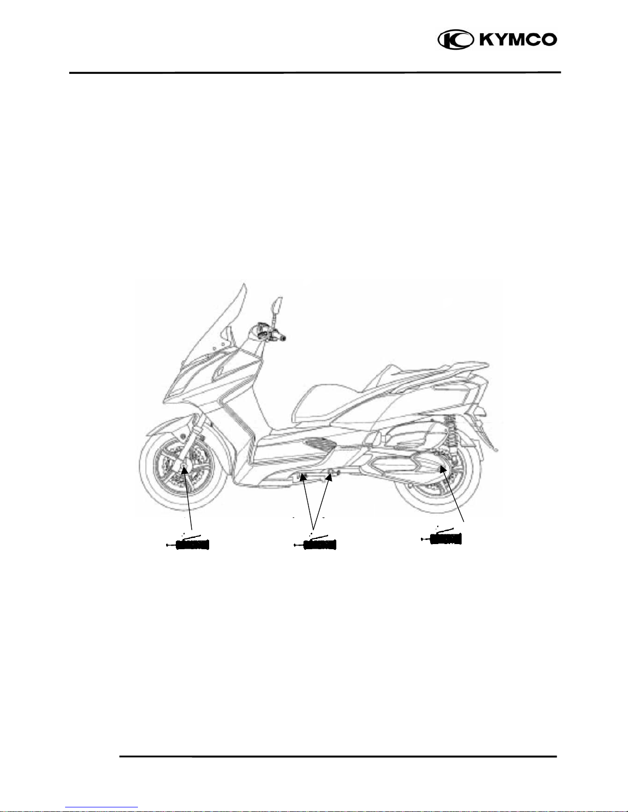
LUBRICATION POINTS
FRAME
The following is the lubrication points for the frame.
Use grease for parts not listed.
Apply engine oil or grease to cables and movable parts not specified. It will avoid abnormal noise
and damage the durability of the motorcycle.
Grease
Grease
Front wheel axle &nut
Rear wheel axle &nut
Grease
Side stand pivot
& Main stand pivot
Page 11
1. GENERAL INFORMATION
1-8
DOWNTOWN 200i
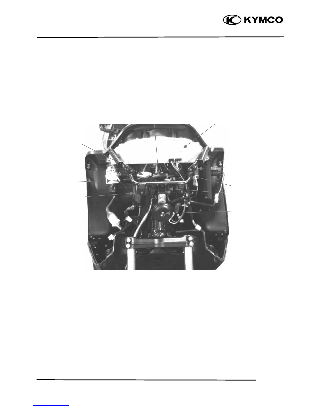
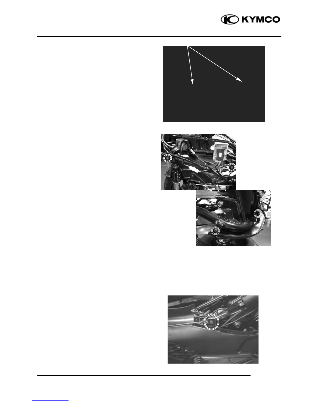
CABLE & HARNESS ROUTING
Tilt Switch Speedometer
Radiator Filler Cap
Ignition Switch
ECU
Horn
Winker Relay
Hi Beam Relay
Lo Beam Relay
Page 12
1. GENERAL INFORMATION
1-9
DOWNTOWN 200i
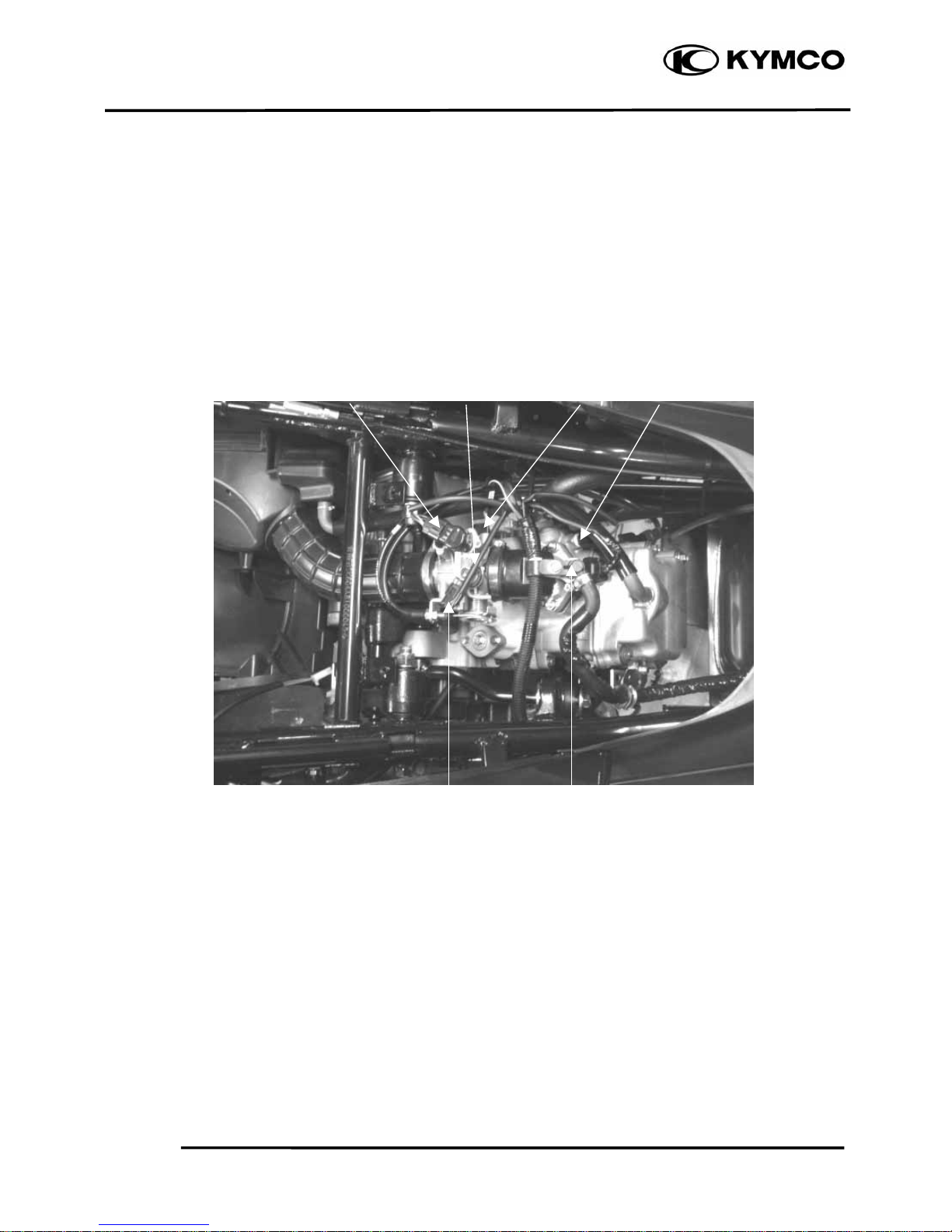
ISC Throttle Body TPS WTS
InjectorMAP Sensor
Page 13
1. GENERAL INFORMATION
1-10
DOWNTOWN 200i
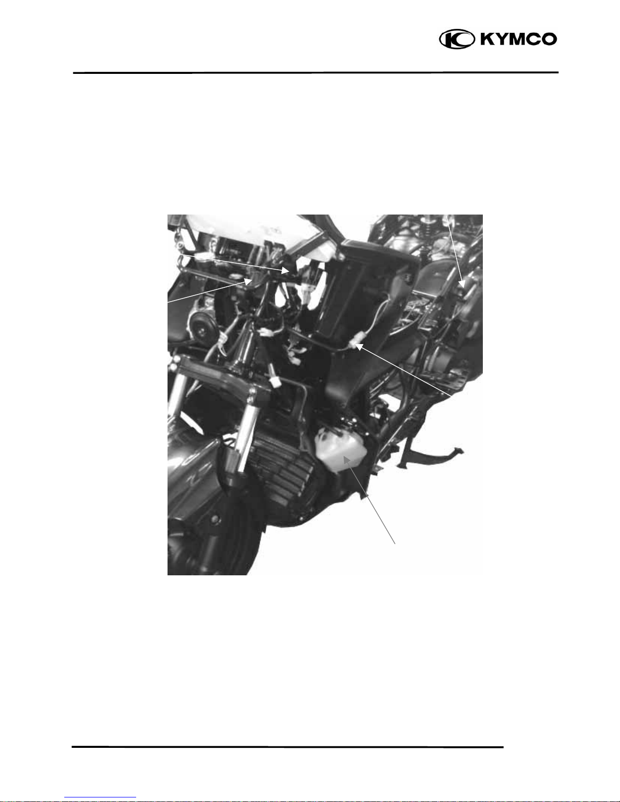
Oil controller
Fuel Pump Relay
Ignition Coil
Output Voltage Connector
Coolant Reserve Tank
Page 14
1. GENERAL INFORMATION
1-11
DOWNTOWN 200i
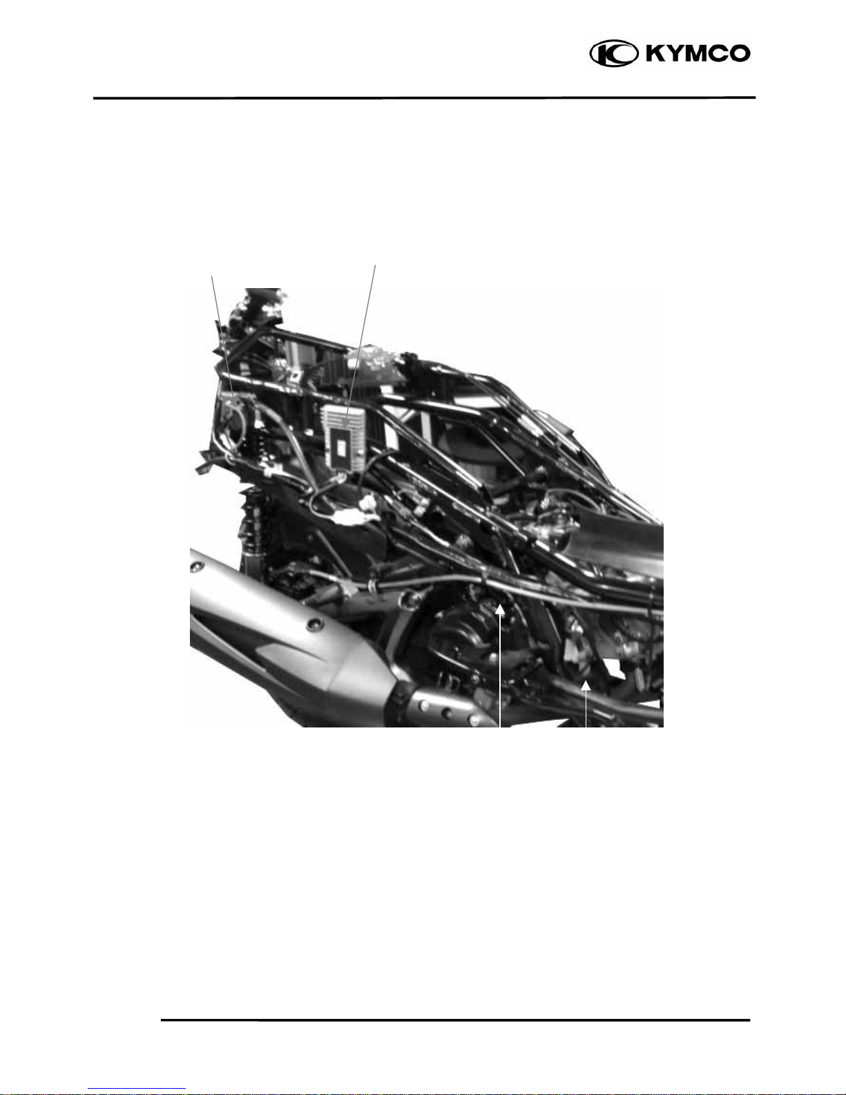
Starter Relay Regulator/Rectifier
CPS O2 Sensor
Page 15

2
. EXHAUST MUFFLER/FRAME COVERS
2-0
DOWNTOWN 200i
2
__________________________________________________________________________________
__________________________________________________________________________________
__________________________________________________________________________________
__________________________________________________________________________________
__________________________________________________________________________________
EXHAUST MUFFLER/FRAME COVERS
__________________________________________________________________________________
SERVICE INFORMATION------------------------------------------------ 2- 1
TROUBLESHOOTING----------------------------------------------------- 2- 1
FASTENER REMOVAL AND REINSTALLATION------------------ 2- 2
FRAME COVERS REMOVAL/INSTALLATION--------------------- 2- 3
EXHAUST MUFFLER ----------------------------------------------------- 2-14
2
Page 16

2
. EXHAUST MUFFLER/FRAME COVERS
2-1
DOWNTOWN 200i
SERVICE INFORMATION
GENERAL INSTRUCTIONS
• When removing frame covers, use care not to pull them by force because the cover joint claws
may be damaged.
• Make sure to route cables and harnesses according to the Cable & Harness Routing.
TORQUE VALUES
Exhaust muffler pipe nuts 1.8~2.2 kgf-m
Exhaust muffler brake /RR Frok 3.2~3.8 kgf-m
RR fork/Engine case 3.0~4.0 kgf-m
TROUBLESHOOTING
Noisy exhaust muffler
• Damaged exhaust muffler
• Exhaust muffler joint air leaks
Lack of power
• Caved exhaust muffler
• Clogged exhaust muffler
• Exhaust muffler air leaks
Page 17
2
. EXHAUST MUFFLER/FRAME COVERS
2-2
DOWNTOWN 200i
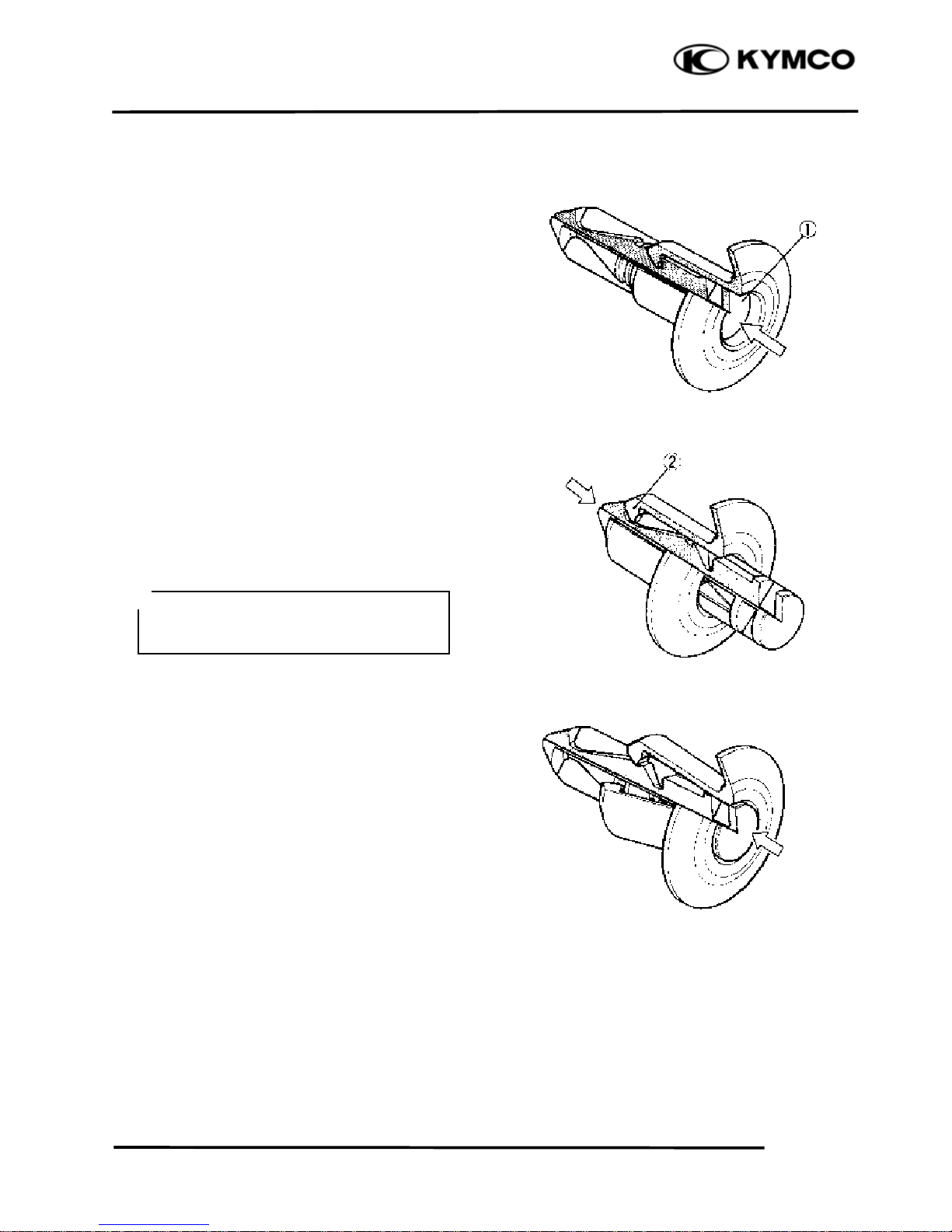
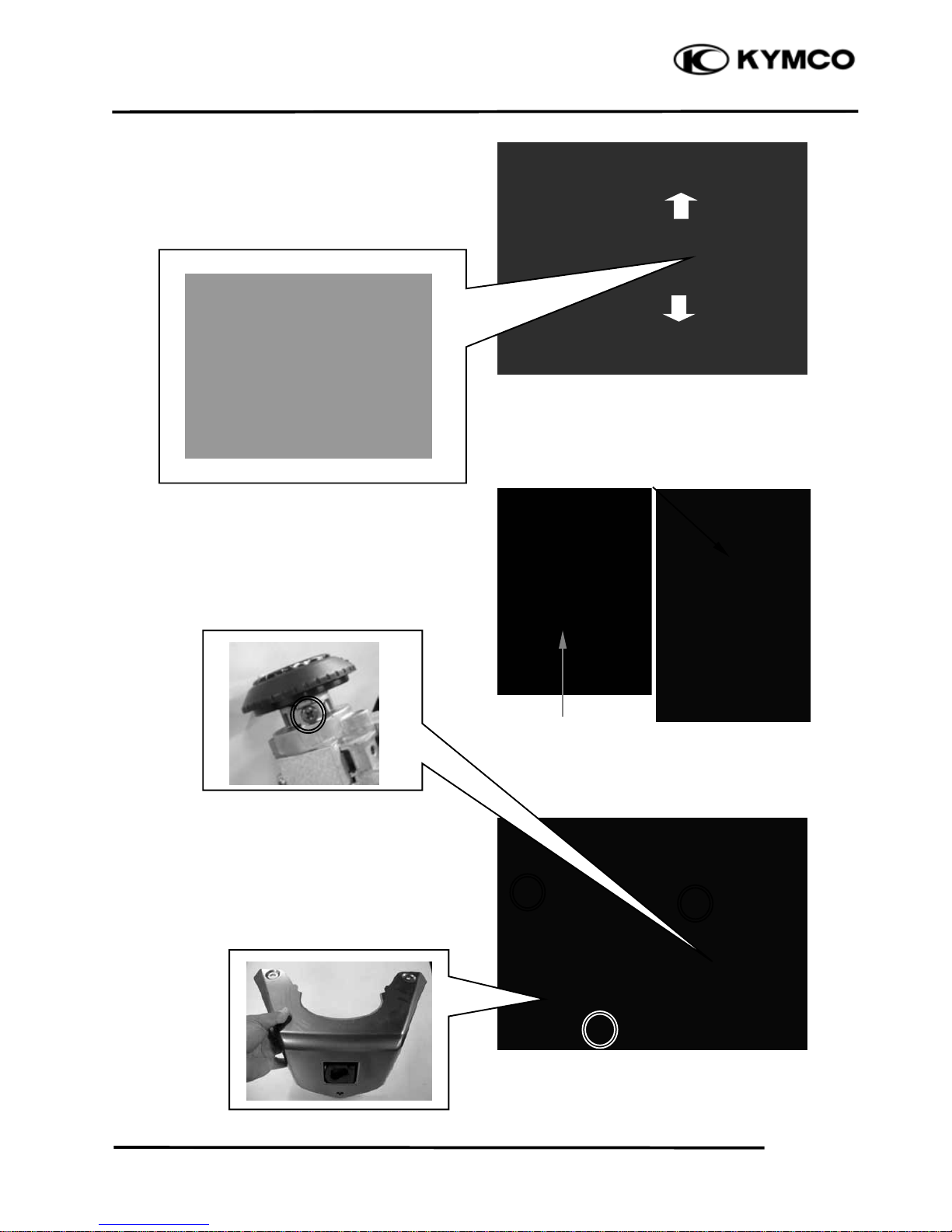
FASTENER REMOVAL AND
REINSTALLATION
REMOVAL
Depress the head of fastener center piece {.
Pull out the fastener.
INSTALLATION
Let the center piece stick out toward the head
so that the pawls | close.
Insert the fastener into the installation hole.
Push in the head of center piece until it
becomes flush with the fastener outside face.
To prevent the pawl | from damage,
insert the fastener all the way into the
installation hole
*
Page 18
2
. EXHAUST MUFFLER/FRAME COVERS
2-3
DOWNTOWN 200i
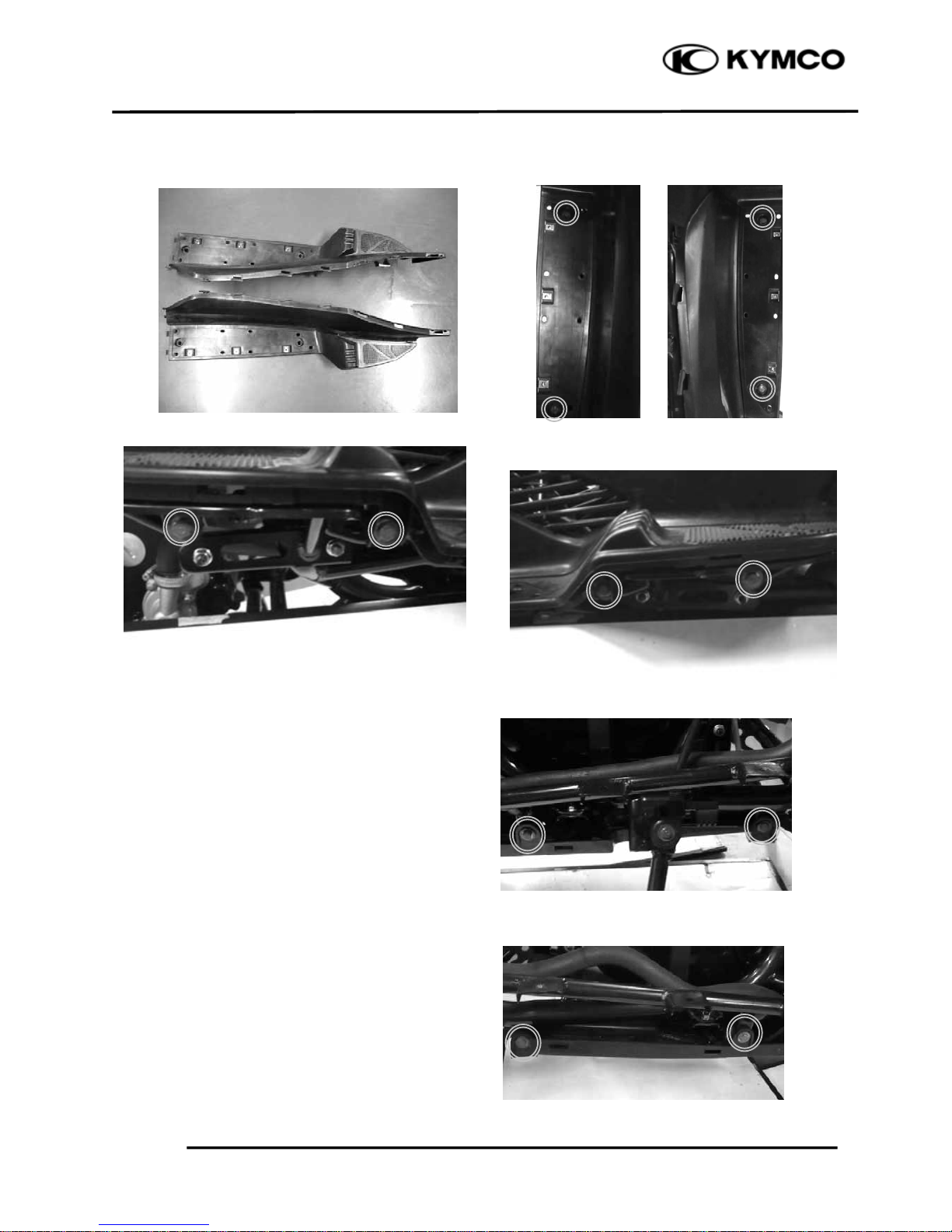
FRAME COVERS REMOVAL/
INSTALLATION
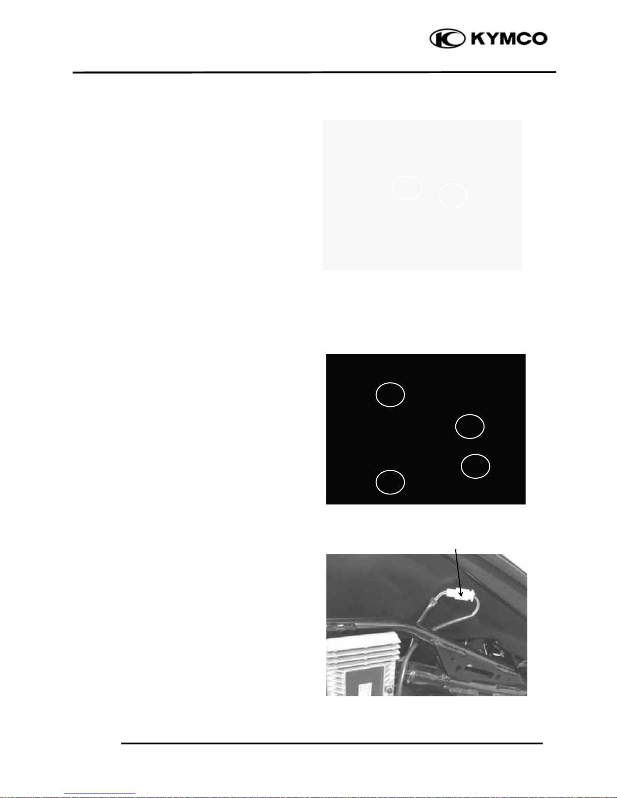
SEAT
Unlock the seat with the ignition key.
Open the seat.
Remove the two nuts and the seat.
Installation is in the reverse order of removal.
LUGGAGE BOX
Unlock the seat with the ignition key.
Open the seat.
Remove four bolts, and the fastener on the
right side of luggage box, then lift luggage
box.
Disconnect the luggage box light connector,
then remove the luggage box.
Installation is in the reverse order of removal.
Luggage Box Light Connecto
r
Page 19
2
. EXHAUST MUFFLER/FRAME COVERS
2-4
DOWNTOWN 200i
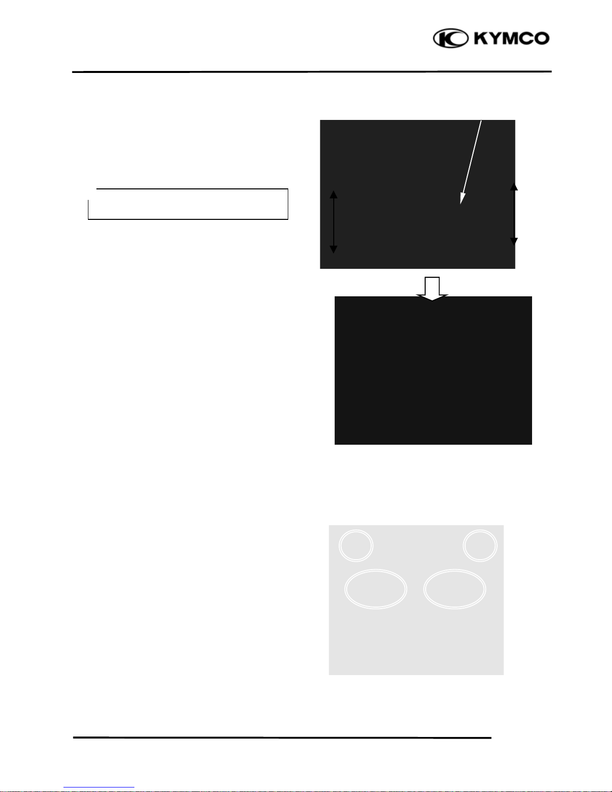
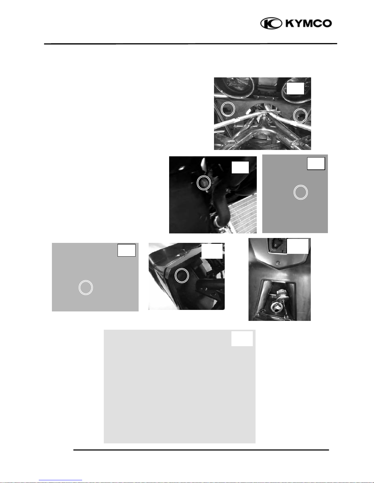
CENTER COVER
Remove the luggage box.
Remove the center cover.
Installation is in the reverse order of removal.
Remove four bolts and then remove the rear
carrier.
Center Cove
r
During removal, do not pull the joint
claws forcedly to avoid damage.
*
Page 20
2
. EXHAUST MUFFLER/FRAME COVERS
2-5
DOWNTOWN 200i
Installation is in the reverse order of removal.
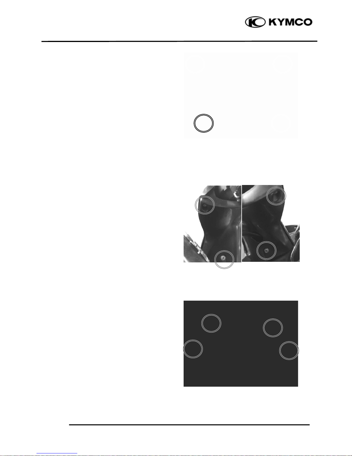
UPPER/LOWER HANDLEBAR COVER
Remove the four screws and then remove
upper handlebar cover.
Remove the four screws, then remove the
bottom handlebar cover.
Disconnect the throttle cable refer to the
“THROTTLE BODY /TPS” section, then
pull the throttle cable out from the lower
cover. Remove the lower cover.
Installation is in the reverse order of removal.
Page 21
2
. EXHAUST MUFFLER/FRAME COVERS
2-6
DOWNTOWN 200i
WINDSHIELD/WINDSHIELD GARNISH
Remove five bolts and windshield garnish.
Page 22
2
. EXHAUST MUFFLER/FRAME COVERS
2-7
DOWNTOWN 200i
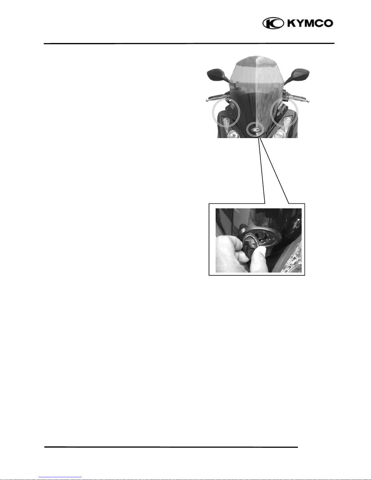
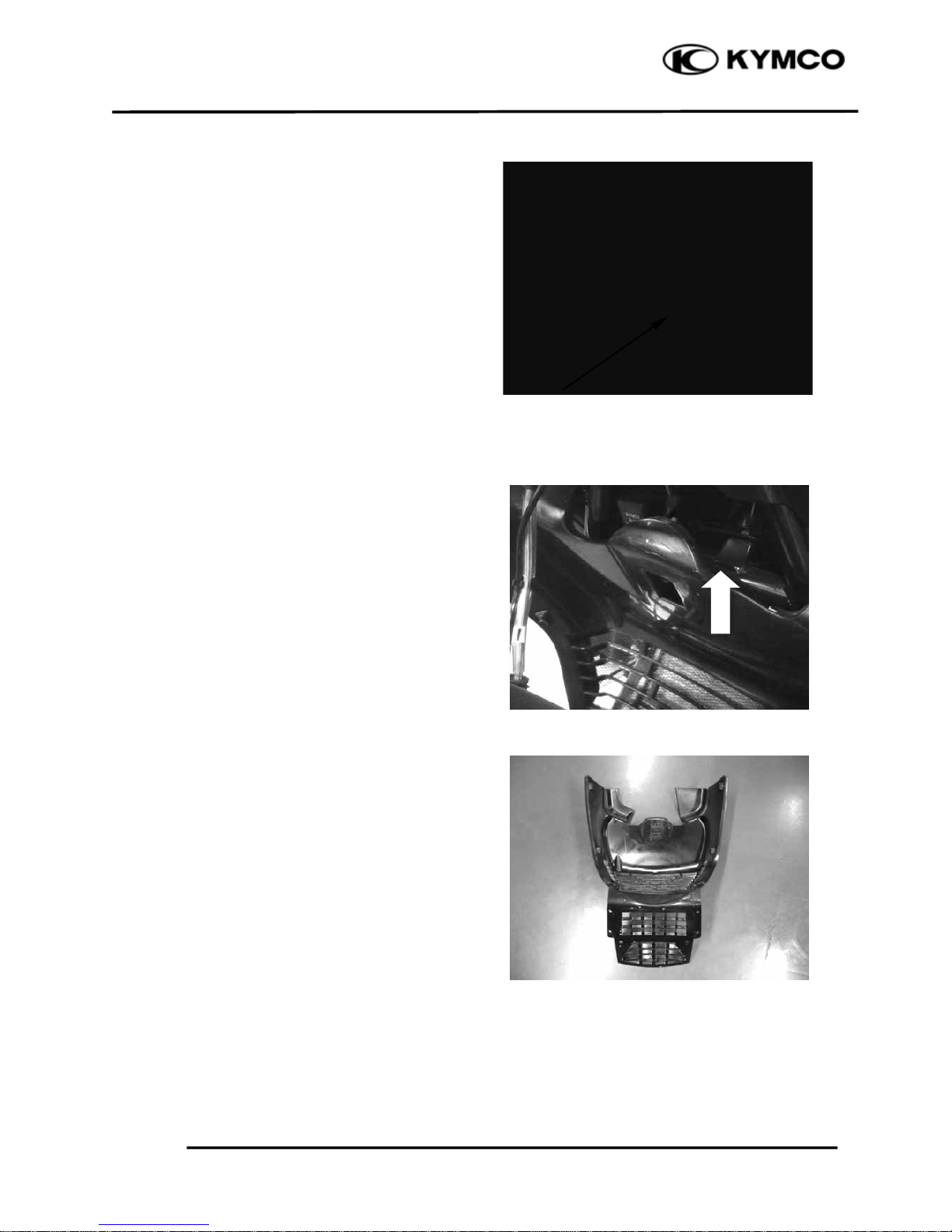
FRONT CENTER COVER
Remove the windshield
Remove four screws, then remove the front
center cover.
Remove the front cover.
Installation is in the reverse order of removal.
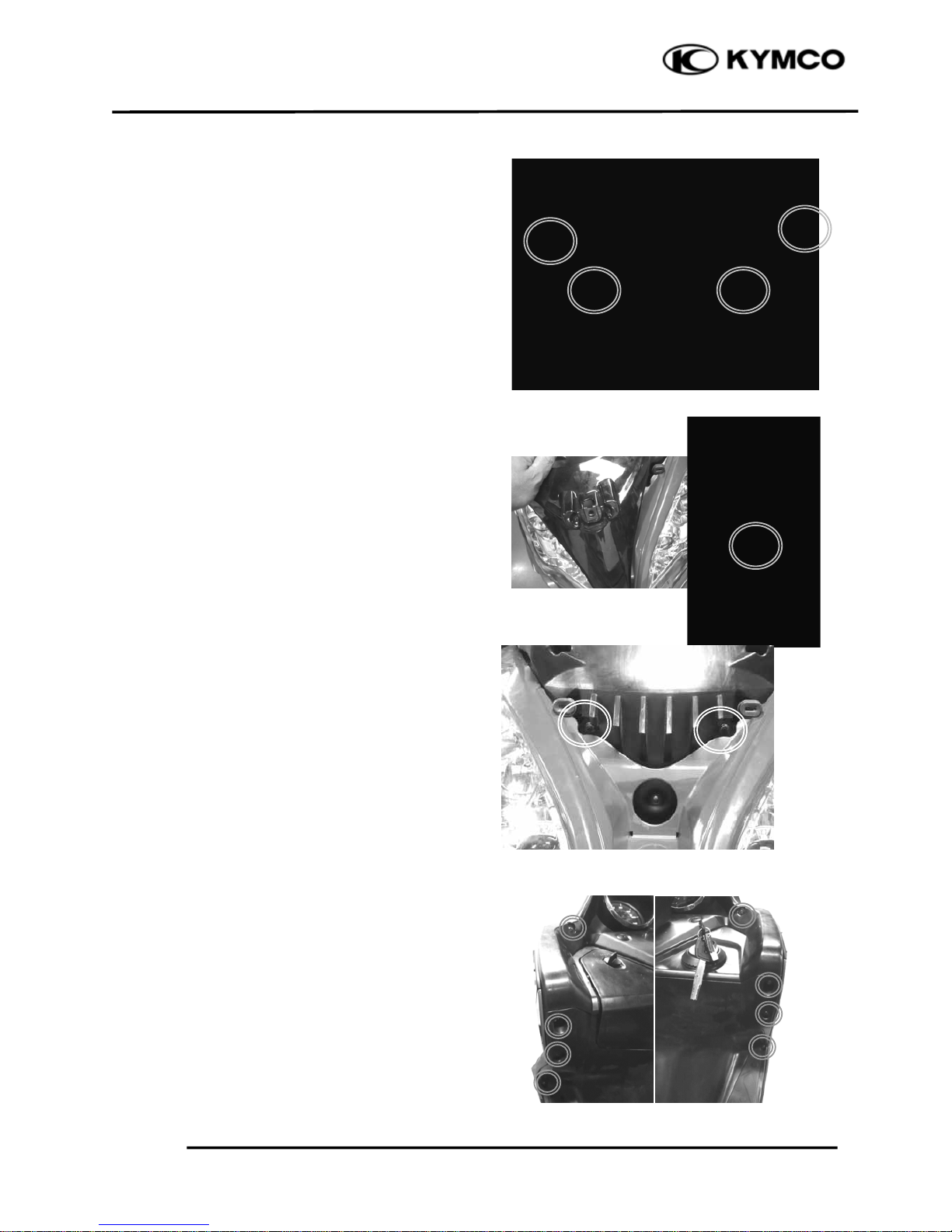
FRONT COVER
Remove the small front cover(black) screw
Remove the small front cover(black)
Remove two nuts.
Remove eight screws from the inner cover.
Remove the front cover
Page 23
2
. EXHAUST MUFFLER/FRAME COVERS
2-8
DOWNTOWN 200i
Disconnect the headlight/position light
connector and right/left turn signal light
connectors.
Installation is in the reverse order of removal.
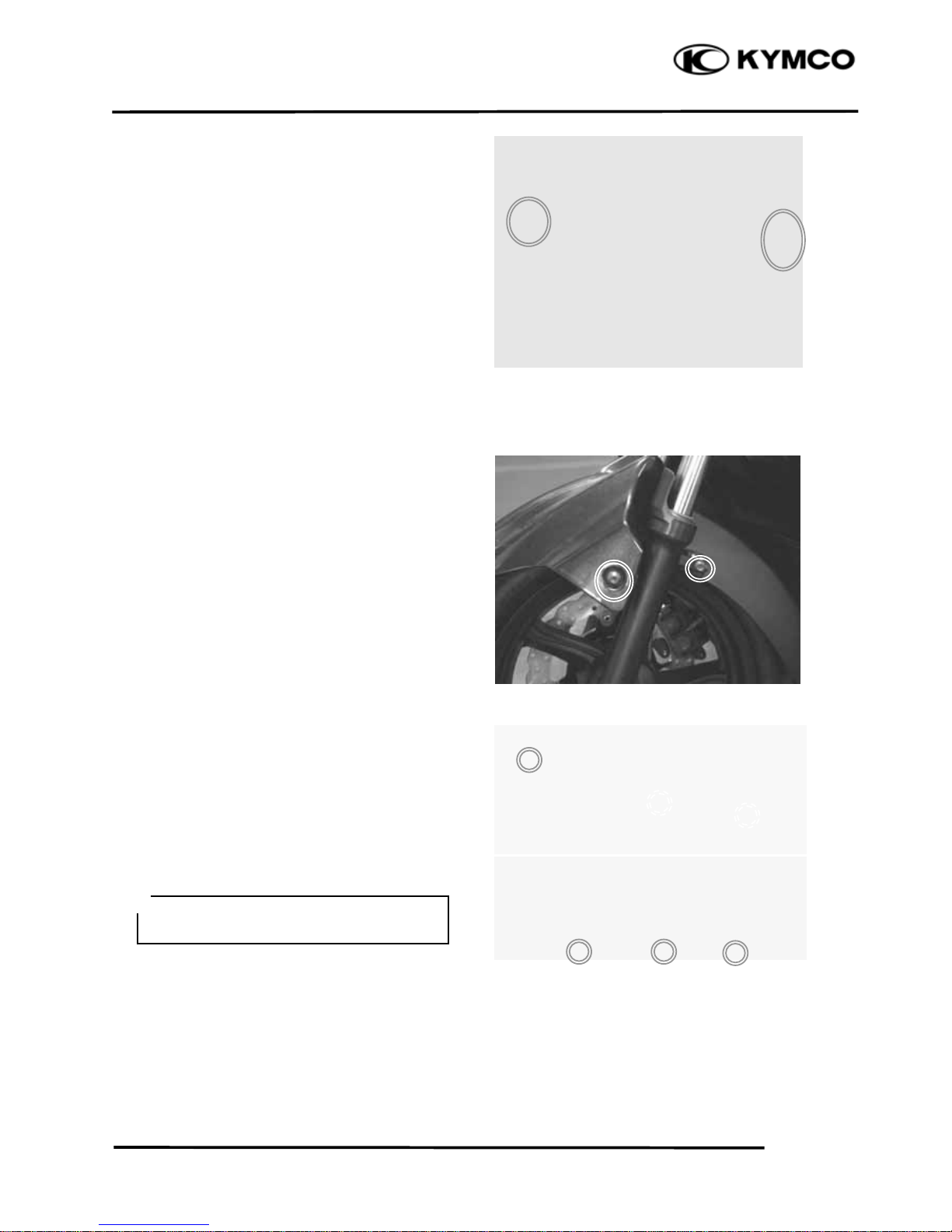
FRONT FENDER
Remove four screws attaching to the front
fender.
Installation is in the reverse order of removal.
RIGHT/LEFT FOOT SKIRT
Remove the six screws attaching to the right
or left skirt.
Installation is in the reverse order of removal.
During removal, do not pull the joint
claws forcedly to avoid damage.
*
Page 24
2
. EXHAUST MUFFLER/FRAME COVERS
2-9
DOWNTOWN 200i
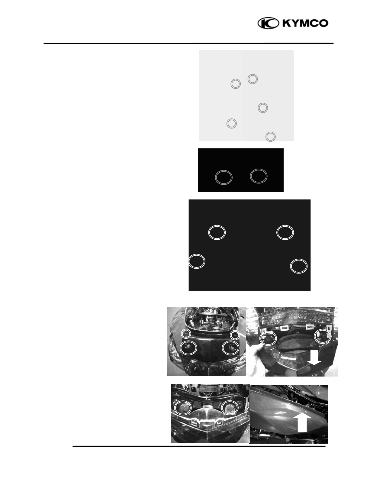
FRONT LOWER COVER
Remove the front cover
Remove the foot skirt
Remove seven screws and front lower cover.
Installation is in the reverse order of removal.
REAR FENDER
Remove the body cover and then the rear
fender.
Installation is in the reverse order of removal.
BODY COVER
Remove the rear center cover.
Remove the right and left foot skirts
Remove the rear carrier.
Remove six screws and two nuts, then
remove the body cover.
Disconnect the taillight connector.
Page 25
2
. EXHAUST MUFFLER/FRAME COVERS
2-10
DOWNTOWN 200i
TIRE FENDER
Remove the body cover.
Remove four bolts attaching to the tire fender
Installation is in the reverse order of removal.
FLOORBOARD
Remove the body cover
Remove the right /left skirt
Remove two screws.
Taillight Connecto
r
Page 26
2
. EXHAUST MUFFLER/FRAME COVERS
2-11
DOWNTOWN 200i
Remove eight bolts, then remove the
floorboard.
UNDER COVER
Remove four bolts
Remove the under cover.
Page 27
2
. EXHAUST MUFFLER/FRAME COVERS
2-12
DOWNTOWN 200i
Remove the fuel tank cap cover.
Installation is in the reverse order of removal.
METER PANEL
Disconnect the speedometer wires.
Disconnect the DC power connectors.
Remove one screws
Remove the ignition key garnish
Remove three screws from the inner cover,
then remove the handler panel.
Installation is in the reverse order of removal.
Speedometer Wires
DC power Connectors
Page 28
2
. EXHAUST MUFFLER/FRAME COVERS
2-13
DOWNTOWN 200i
INNER COVER
Remove the front cover.
Remove the front lower cover.
Remove the floorboard
Remove four bolts and front glove box one
screw.
Remove two fastener bolts, then remove
the fuel tank fill cap.
Remove the inner cover
(3)
(1)
(2)
(2)
(4)
(5)
(6)
Page 29
2
. EXHAUST MUFFLER/FRAME COVERS
2-14
DOWNTOWN 200i
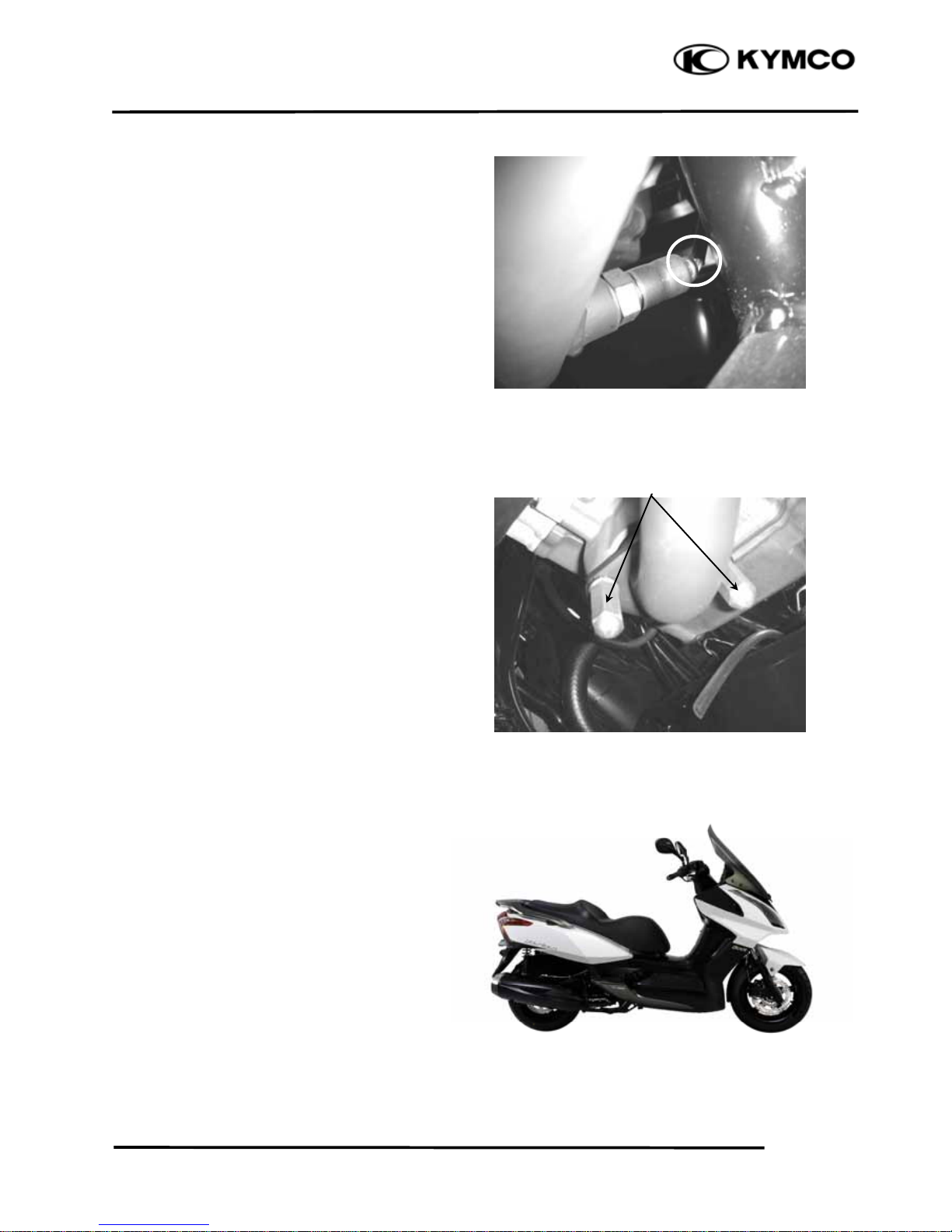
EXHAUST MUFFLER
REMOVAL
Disconnect the connector with O2 heater/O2
sensor.
Remove the two exhaust pipe joint nuts
Remove three muffler mount bolts and
muffler and gasket.
N
uts
Page 30
2
. EXHAUST MUFFLER/FRAME COVERS
2-15
DOWNTOWN 200i
INSTALLATION
Replace the gasket with a new one.
Install the exhaust muffler and three
mounting bolt.
Install and tighten the two exhaust pipe joint
nuts to the specified torque
Torque: 20 N•m (2 kgf•m,)
Tighten the three mounting bolts
Torque: 35 N•m (3.5 kgf•m,)
Remove the coolant tank cover.
Gaske
t
Page 31

3. INSPECTION/ADJUSTMENT
3-0
DOWNTOWN 200i
3
________________________________________________________________________________
________________________________________________________________________________
________________________________________________________________________________
________________________________________________________________________________
INSPECTION / ADJUSTMENT
_________________________________________________________________________________________
SERVICE INFORMATION ----------------------------------------------------------------------- 3- 1
MAINTENANCE SCHEDULE ------------------------------------------------------------------- 3- 2
THROTTLE OPERATION ------------------------------------------------------------------------ 3- 3
ENGINE OIL----------------------------------------------------------------------------------------- 3- 4
RESERVE TANK ----------------------------------------------------------------------------------- 3- 5
AIR CLEANER-------------------------------------------------------------------------------------- 3- 6
SPARK PLUG --------------------------------------------------------------------------------------- 3- 6
VALVE CLEARANCE----------------------------------------------------------------------------- 3- 7
CYLINDER COMPRESSION--------------------------------------------------------------------- 3- 7
FINAL REDUCTION GEAR OIL---------------------------------------------------------------- 3- 8
DRIVE BELT ---------------------------------------------------------------------------------------- 3- 8
BRAKE SYSTEM----------------------------------------------------------------------------------- 3- 9
CLUTCH SHOE WEAR --------------------------------------------------------------------------- 3- 10
SUSPENSION --------------------------------------------------------------------------------------- 3- 10
NUTS/BOLTS/FASTENERS---------------------------------------------------------------------- 3- 11
WHEELS/TIRES ------------------------------------------------------------------------------------ 3- 11
STEERING HANDLEBAR------------------------------------------------------------------------ 3- 11
SIDE STAND ---------------------------------------------------------------------------------------- 3- 12
3
Page 32

3. INSPECTION/ADJUSTMENT
3-1
DOWNTOWN 200i
SERVICE INFORMATION
GENERAL
! WARNING
• Before running the engine, make sure that the working area is well ventilated. Never run the engine in a
closed area. The exhaust contains poisonous carbon monoxide gas, which may cause death to people.
• Gasoline is extrem
ely flammable and is explosive under some conditions. The working area must be
well ventilated and do not smoke or allow flames or sparks near the working area or fuel storage area.
SPECIFICATIONS
ENGINE
Throttle grip free play : 2~6 m
m
Spark plug : NGK: CR7E
Spark plug gap : 0.6 mm ~ 0.7 mm
Valve clearance : IN: 0.10 mm EX: 0.10 mm
Idle speed : 1600±100 rpm
Engine oil capacity:
Cylinder compression: 16±2 kg/cm²
At disassembly : 1.5 Liter Ignition timing : ECU
At change : 1.3 Liter Coolant type : Water Cooling
Gear oil capacity :
At disassembly : 0.23 Liter
At change : 0.21 Liter
TIRE
1 Rider 2 Riders
Front 2.00 kg/cm² 2.00 kg/cm²
Rear 2.25 kg/cm² 2.25 kg/cm²
TIRE SPECIFICATION
Front : 120/80-14 58S
Rear : 150/70-13 64S
TORQUE VALUES
Front axle nut : 2 kg-m
Rear axle nut : 12 kg-m
SPECIAL TOOL
Tappet Adjuster E012
Page 33

3. INSPECTION/ADJUSTMENT
3-2
Page 34

3. INSPECTION/ADJUSTMENT
3-3
DOWNTOWN 200i
THROTTLE OPERATION
Check the throttle grip for smooth movement.
Measure the throttle grip free play.
Free Play: 2~6 m
m
Major adjustment of the throttle grip free play is
m
ade with the adjusting nut at the throttle body
side. Adjust by loosening the lock nut and turning
the adjusting nut.
Minor adjustment is made with the adjusting nut
at the throttle grip side.
Slide the rubber cover(1) out and adjust by
loosening the lock nut(3) and turning
the
adjusting nut(2).
Lock Nu
t
Adjusting Nu
t
Page 35

3. INSPECTION/ADJUSTMENT
3-4
DOWNTOWN 200i
ENGINE OIL
OIL LEVEL INSPECTION
Stop the engine and support the scooter upright
on the level ground.
Wait for 2~3 m
inutes and check the oil level
with the dipstick. Do not screw in the dipstick
when checking the oil level.
OIL CHANGE
Remove the oil drain bolt to drain the engine oil.
Install the aluminum washer and tighten the oil
drain bolt.
Torque: 2.5 kg-m
Pour the recommended oil through the oil filler
hole.
OIL CAPACITY
Engine oil capacity: 1.5 L
Engine oil exchanging capacity: 1.3 L
Engine Oil Viscosity : SAE 5W50
OIL FILTER SCREEN INSPECTION
Drain the engine oil.
Remove the oil filter screen attaching the leftunder crankcase.
Clean the oil filter screen.
Install the oil filter screen and filter screen cap.
Fill the engine with recommended engine oil.
OIL FILTER REPLACEMENT
Remove the oil filler cap attaching the right-under
crankcase cover.
• Replace the aluminum washer with a new
one if it is deformed or damaged.
*
Dipstick
Oil Drain Bol
t
Oil Filter Screen
Oil Filter Cap
Page 36

3. INSPECTION/ADJUSTMENT
3-5
DOWNTOWN 200i
The spring will come out when the filter cap is
removed.
Let the engine oil drain out.
Check that the O-ring is in good condition.
Install a new oil filter.
RESERVE TANK
COOLANT LEVEL INSPECTION
The reserve tank is under left floorboard .Check the
coolant level through the inspection window(1) at the
left side skirt white the engine is at the normal
operating temperature , with the scooter In an upright
position.
If the coolant level is below the LOWER level
m
ark(3), remove the left floor mat ,remove the lid
screw(4), the reserve tank lid(5), and then the reserve
tank cap(6) to add coolant mixture until it reaches the
upper level mark .
Spring
Make sure the rubber seal on the oil filter
facing the left crankcase.
*
Add coolant to the reserve tank only. Do not
attempt to add coolant by removing the
radiator cap. Coolant in the radiator is under
pressure and is very hot and can cause
serious burns.
*
Page 37

3. INSPECTION/ADJUSTMENT
3-6
DOWNTOWN 200i
AIR CLEANER
AIR FILTER REPLACEMENT
Remove the body cover.
Remove seven screws attaching to the air cleaner
cover.
Remove six screws attaching to the filter.
Check the filter and replace it if it is excessively
dirty
or damaged.
CHANGE INTERVAL
More frequent replacement is required when
riding in unusually dusty or rainy areas.
SPARK PLUG
Remove the spark plug cap and spark plug.
Check the spark plug for wear and fouling
deposits.
Clean any fouling deposits with a spark plug
cleaner or a wire brush.
Specified Spark Plug: NGK-CR7E
Measure the spark plug gap.
Spark Plug Gap: 0.6 – 0.7 m
m
Torque:17.2 N-m
• The air cleaner element has a viscous type
paper element. Do not clean it with
compressed air.
• Be sure to install the air cleaner element
and cover securely.
*
• When installing, first screw in the spark
plug by hand and then tighten it with a
spark plug wrench.
*
Air Cleaner Cove
r
Deformation
0.6~0.7 mm
}
Gap
Wear
Fouling
Deposits
Cracks
Damage
Spark Plug
Page 38

3. INSPECTION/ADJUSTMENT
3-7
DOWNTOWN 200i
VALVE CLEARANCE
Remove the seat assy and luggage box.
Remove the four bolts and then cylinder head
cover.
Turn the A.C. generator flywheel to the top dead
center (TDC) on
the compression stroke so that
the “T” mark on the flywheel aligns with the
index mark on the left crankcase cover.
Inspect and adjust valve clearance.
Valve Clearance:
IN: 0.10 mm
EX: 0.10 mm
Loosen the lock nut and adjust by turning the
adjusting nut
Valve Adjuster E012
Feeler Gauge
CYLINDER COMPRESSION
Warm up the engine before compression test.
Remove the center cover and luggage box.
Remove the spark plug.
Insert a compression gauge.
Open the throttle fully and push the starter button
to test the com
pression.
Max. Compression: 16±2 kg/cm
2
If the compression is low, check for the following:
‧Leaky
valves
‧Valve clearance too sm
all
‧Leaking cy
linder head gasket
‧Worn piston rings
‧Worn piston/cy
linder
If the compression is high, it indicates that carbon
deposits have accum
ulated on the combustion
chamber and the piston head.
• Inspect and adjust valve clearance while
the engine is cold (below 35℃).
*
• Check the valve clearance again after the
lock nut is tightened.
*
Bolts
Top Dead Center Mark
Special
Cylinder Head Cove
r
Page 39

3. INSPECTION/ADJUSTMENT
3-8
DOWNTOWN 200i
FINAL REDUCTION GEAR OIL
Remove the transmission fluid drain bolt.
Remove the transmission fluid filler bolt, then
slowly
rotate the rear wheel to drain the fluid.
Fill the transmission with the recommend fluid to
the capacity
listed below.
Transmission fluid type: SAE 90
Transmission fluid capacity: 0.23 L
Transmission fluid exchanging
capacity: 0.21 L
Install the transmission filler bolt and tighten it to
the specified torque.
DRIVE BELT
Remove the left crankcase cover.
Inspect the drive belt for cracks or excessive wear.
Replace the drive belt with a new one if necessary
and in accordance with the Maintenance Schedule.
Oil FillerBol
t
• Place the scooter on its main stand on level
ground.
*
Oil Drain Bol
t
Drive Bel
t
Page 40

3. INSPECTION/ADJUSTMENT
3-9
DOWNTOWN 200i
BRAKE SYSTEM
There is adjuster on each brake lever.Each
adjuster has four positions so that the released
lever position can be adjusted to suit the rider’s
hands.
To adjust the distance of the lever from the
handlebar grip,push
the lever(1) forward and turn
the adjuster knob(2) to align the number with the
arrow mark(3) on the lever holder.
BRAKE DISK/BRAKE PAD
Check the brake disk surface for scratches,
unevenness or abnormal wear.
Check if the brake disk runout is within the
specified service lim
it.
Check if the brake pad wear exceeds the wear
indicator line.
BRAKE FLUID
Turn the steering handlebar upright and check if
both brake fluid levels is at the upper limit. If the
brake fluid is insufficient, fill to the upper limit.
Specified Brake Fluid: DOT-4
Keep grease or oil off the brake disk to
avoid brake failure.
*
The brake fluid level will decrease if the
brake pads are worn.
*
Page 41

3. INSPECTION/ADJUSTMENT
3-10
DOWNTOWN 200i
CLUTCH SHOE WEAR
Start engine and check the clutch operation by
increasing the engine speed gradually.
If the motorcycle tends to creep or the engine stop,
check the
clutch shoes for wear and replace if
necessary.
SUSPENSION
FRONT
Check the action of the front shock absorbers by
compressing them several times.
Check the entire shock absorber assembly for oil
leaks, looseness or dam
age.
REAR
Each shock absorber(4) on your scooter has 5
spring preload adjustment positions for different
load or riding conditions.
Use a pin spanner(5) to adjust the rear shock
spring
preload. Position 1 is for light loads and
smooth road conditions. Position 3 to 5 increase
spring preload for a stiffer rear suspension and
can be used when the scooter is heavily loaded.
Be certain to adjust both shock absorbers to the
sam
e spring preload positions.
Page 42

3. INSPECTION/ADJUSTMENT
3-11
DOWNTOWN 200i
NUTS/BOLTS/FASTENERS
Check all important chassis nuts and bolts for
looseness.
Tighten them to their specified torque values if
any
looseness is found.
WHEELS/TIRES
Check the tires for cuts, imbedded nails or other
damages.
Check the tire pressure.
Tire Pressure
1 Rider 1 Rider (with
passenger)
Front 2.00 kg/cm² 2.00 kg/cm²
Rear 2.25 kg/cm² 2.25 kg/cm²
Tire Size:
Front 120/80-14 58S
Rear 150/70-13 64S
Check the front axle nut for looseness.
Check the rear axle nut for looseness.
If the axle nuts are loose, tighten them to the
specified torques.
Torque:
Front axle nut 2 kg-m
Rear axle nut 12 kg-m
STEERING HANDLEBAR
Raise the front wheel off the ground and check
that the steering handlebar rotates freely.
If the handlebar moves unevenly, binds, or has
vertical m
ovement, adjust the steering head
bearing.
• Tire pressure should be checked when tires
are cold.
*
Front Axle Nut
Rear Axle Nut
Page 43

3. INSPECTION/ADJUSTMENT
3-12
DOWNTOWN 200i
SIDE STAND
Your scooter's side stand is not only necessary when
you park, but it contains an important safety feature.
This feature cuts-off the ignition if you try to ride the
scooter when the side stand is down. Perform the
following side stand inspection.
INTERLOCK FUNCTION CHECK
Check the side stand ignition cut-off system,
1. Place the scooter on its center stand.
2. Put the side stand up and start the engine.
3. Lower the side stand. The engine should stop as
you put the side stand down.
If the side stand system does not operate as
described, see your KYMCO dealer for
service.
*
Page 44

4. LUBRICATION SYSTEM
4-0
DOWNTOWN 200i
4
________________________________________________________________________________
________________________________________________________________________________
________________________________________________________________________________
________________________________________________________________________________
________________________________________________________________________________
LUBRICATION SYSTEM
________________________________________________________________________________
LUBRICATION SYSTEM------------------------------------------------------------------------- 4-1
SERVICE INFORMATION ----------------------------------------------------------------------- 4-2
TROUBLESHOOTING ---------------------------------------------------------------------------- 4-2
ENGINE OIL/OIL FILTER------------------------------------------------------------------------ 4-3
OIL PUMP-------------------------------------------------------------------------------------------- 4-5
4
Page 45

4. LUBRICATION SYSTEM
4-1
DOWNTOWN 200i
LUBRICATION PART
Dipstick
Oil Filter
Oil Pump
Drive Chain
Page 46

4. LUBRICATION SYSTEM
4-2
DOWNTOWN 200i
SERVICE INFORMATION
GENERAL INSTRUCTIONS
• The m
aintenance of lubrication system can be performed with the engine installed on the frame.
• Drain the coolant before starting any
operations.
• Carefully
when removing and installing the oil pump not to allow dust and foreign matters to enter the
engine and oil line.
• Do not attem
pt to disassemble the oil pump. The oil pump must be replaced as a set when it reaches its
service limit.
• After the oil pum
p is installed, check each part for oil leaks.
SPECIFICATIONS
ENGINE OIL
Engine Oil Capacity At disassembly: 1.5 liter At change: 1.3 liter
Recommended Oil SAE5W50# API: SJ
TROUBLESHOOTING
Oil level too low Poor lubrication pressure
• Natural oil consum
ption • Oil level too low
• Oil leaks • Clogged oil filter or oil passage
• Worn piston rings • Faulty
oil pump
• Worn valve guide
• Worn valve guide seal
Oil contamination
• Oil not changed often enough
• Faulty
cylinder head gasket
• Loose cy
linder head bolts
Page 47

4. LUBRICATION SYSTEM
4-3
DOWNTOWN 200i
ENGINE OIL/OIL FILTER
Remove the oil dipstick and check the oil level
with the oil dipstick.
If the level is near the lower level, fill to the upper
level with the recom
mended engine oil.
OIL CHANGE
Remove the oil drain bolt located at the left side
of the engine to drain the engine oil.
After the oil has been completely drained, install
the
aluminum washer and tighten the oil drain
bolt.
Torque: 24.5
N-m
Pour the recommended oil through the oil filler
hole.
OIL FILTER SCREEN
Drain the engine oil.
Remove the oil filter screen cap.
Remove the oil filter screen and spring.
Check the oil filter screen for clogging or damage
and
replace if necessary. Check the filter screen
O-ring for damage and replace if necessary.
Install the oil filter screen, spring, O-ring and
filter screen cap.
Torque: 12.7N-m
Recommended Oil: SAE5W50# API: SJ
Oil Capacity:
At disassembly: 1.5 liter
At change: 1.3 liter
Start the engine and check for oil leaks. Start
the engine and let it idle for few m
inutes, then
recheck the oil level.
Oil Dipstick
• Place the scooter upright on level ground
for engine oil level check.
• Run the engine for 2~3 minutes and check
the oil level after the engine is stopped for
2~3 minutes.
*
• The engine oil will drain more easily while
the engine is warm.
*
Page 48

4. LUBRICATION SYSTEM
4-4
DOWNTOWN 200i
OIL FILTER REPLACEMENT
Remove the oil filler cap attaching the right-under
crankcase cover.
The spring will come out when the filter cap is
rem
oved.
Let the engine oil drain out.
Check that the O-ring is in good condition.
Install a new oil filter.
Oil Filter Cap
Spring
Make sure the rubber seal on the oil filter
facing the left crankcase
*
Page 49

4. LUBRICATION SYSTEM
4-5
DOWNTOWN 200i
OIL PUMP REMOVAL
Remove twelve bolts attaching the right crankcase
cover.
Remove the A.C. generator flywheel with special
tool.
Special tool:
Flywheel Puller E003
Universal Holder E021
Remove the gasket and dowel pins.
Remove the starter idle gear and starter clutch.
Remove the two bolts and oil separator cover.
Remove the oil pump driven gear clip to remove
the oil pum
p driven gear and drive chain.
Dowel Pin
Starter Idle Gea
r
Oil Separator Cove
r
Oil Pump Drive Chain
Page 50

4. LUBRICATION SYSTEM
4-6
DOWNTOWN 200i
Remove two oil pump mounting bolts and the oil
pump.
OIL PUMP INSTALLATION
Install the oil pump into the crankcase.
After the oil pump is installed, tighten the two
m
ounting bolts.
Install the pump driven gear and drive chain by
aligning
the pump driven gear with the cutout in
the pump shaft.
Install and tighten the pump driven gear bolts.
Install the oil separator cover and tighten the bolts.
Install the starter idle gear and starter clutch.
Install the gasket and dowel pins.
Install the right crankcase cover and tighten the
twelve bolts.
Torque: 1.2 kg-m
Arrow Mark
Pump Shaf
t
Diagonally tighten the bolts in 2~3 times.
*
Install the oil pump with the arrow on the
pump body facing up and fill the oil pump
with engine oil before installation.
*
Oil Separator Cove
r
Dowel Pin
Starter Idle Gea
r
Page 51

5
. ENGINE REMOVAL/INSTALLATION
5-0
DOWNTOWN 200i
5
__________________________________________________________________________________
__________________________________________________________________________________
__________________________________________________________________________________
__________________________________________________________________________________
__________________________________________________________________________________
ENGINE REMOVAL/INSTALLATION
__________________________________________________________________________________
SERVICE INFORMATION------------------------------------------------ 5-1
ENGINE REMOVAL/INSTALLATION
--------------------------------- 5-2
ENGINE HANGER
--------------------------------------------------------- 5-6
5
Page 52

5. ENGINE REMOVAL/INSTALLATION
5-1
DOWNTOWN 200i
SERVICE INFORMATION
GENERAL INSTRUCTIONS
• A floor jack or other adjustable support is required to support and maneuver the engine. Be
careful not to damage the scooter body, cables and wires during engine removal.
• Use shop towels to protect the scooter body during engine removal.
• Drain the coolant before removing the engine.
• After the engine is installed, fill the cooling system with coolant and be sure to bleed air from the
water jacket. Start the engine to check for coolant leaks.
• Before removing the engine, the rear brake caliper must be removed first. Be careful not to bend
or twist the brake fluid tube.
SPECIFICATIONS
Engine oil capacity:
At disassembly: 1.5 L
At change: 1.3 L
Coolant capacity:
Radiator: 870 cc
Hose with cool coolant: 169 cc
Hose with hot coolant: 194 cc
Reserve tank: 490 cc
Total capacity: 1360 cc
TORQUE VALUES
90304-GHE8-0040 Engine hanger (Engine side) 5.0 kgf-m (50 N-m)
90305-LBD4-9000 Engine hanger (Frame side) 6.5 kgf-m (65 N-m)
95801-10060 Rear fork mount bolts 3.5 kgf-m (35 N-m)
90305-KFW6-9120-M1 Rear axle nut 12.0 kgf-m (120 N-m)
95801-10035-00 Rear cushion lower/upper mount bolts 4.0 kgf-m (40 N-m)
Page 53

5
. ENGINE REMOVAL/INSTALLATION
5-2
DOWNTOWN 200i
ENGINE
REMOVAL/INSTALLATION
REMOVAL
Remove the air cleaner
Disconnect the connector including of ISC,
Throttle body, TPS, WTS, MAP sensor and
injector.
Disconnect the O2 sensor connector.
Disconnect the throttle cables.
Disconnect the Regulator/Rectifier
connector.
Disconnect the starter relay wire from
starter motor.
Remove a bolt from fuel hose guide.
Disconnect the fuel hose from fuel injector.
Disconnect the input water hose.
Disconnect the air bleed hose.
Fuel hose guide
Water pumpOil filter
Water hose
Page 54

5. ENGINE REMOVAL/INSTALLATION
5-3
DOWNTOWN 200i
Remove the muffler.
Remove the rear fork mounting bolts (1)
attaching to the crankcase.
Torque: 3.5 kgf-m (35 N-m)
Remove the rear axle nut (2).
Torque: 12.0 kgf-m (120 N-m)
Remove two bolts (3) attaching to rear brake
hose clamps.
Remove two bolts (4) attaching to the rear
brake caliper.
Torque: 3.2 kgf-m (32 N-m)
Disconnect the alternator connector (5).
Disconnect the ignition pulse generator
connector (6).
Release the rubber cap and remove the
terminal screw (7) to disconnect the start
motor cable from the start motor.
Remove the bolt and engine ground cable.
(6) (5)
(7)
(3)
(2)
(1)
(4)
Page 55

5
. ENGINE REMOVAL/INSTALLATION
5-4
DOWNTOWN 200i
Remove the spark plug cap.
Disconnect the lower radiator hose from
lower radiator pipe.
Remove the right and left rear cushion lower
m
ount bolts.
Torque: 4.0 kgf-m
(40N-m)
Spark Plug Cap
Mount Bolt
Radiator Hose
Page 56

5. ENGINE REMOVAL/INSTALLATION
5-5
DOWNTOWN 200i
Remove the engine mount nut and pull it out.
Remove the engine from the frame.
Torque: 6.5 kgf-m (65 N-m)
INSTALLATION
Installation is in the reverse order of removal.
After installation, inspect and adjust the
following:
• Throttle grip free play
• Fill the cooling system with coolant and
start the engine to bleed air from the system.
API/ABV Reset (Refer to chapter14, page 17)
At removing the engine, be careful not
to catch your hand or finger between
the engine hanger and crankcase.
*
Mount Nut
Page 57

5
. ENGINE REMOVAL/INSTALLATION
5-6
DOWNTOWN 200i
ENGINE HANGER
REMOVAL
Remove the engine mount nut and pull it out.
Remove the left/right engine hanger mount
bolt.
Remove the engine from frame.
INSTALLATION
Installation is in the reverse order of removal.
Tighten the engine hanger mount bolts to the
specified torque.
Torque: 6.5 kgf-m (65 N-m)
Be careful to put the engine down.
*
Mount Nut
Page 58

6. CYLINDER HEAD/VALVES
6-0
DOWNTOWN 200i
6 .
________________________________________________________________________________
________________________________________________________________________________
________________________________________________________________________________
________________________________________________________________________________
________________________________________________________________________________
CYLINDER HEAD/VALVES
_________________________________________________________________________________________
SCHEMATIC DRAWING------------------------------------------------------------------------- 6-1
SERVICE INFORMATION ----------------------------------------------------------------------- 6- 2
TROUBLESHOOTING ---------------------------------------------------------------------------- 6- 3
CYLINDER HEAD COVER REMOVAL------------------------------------------------------- 6- 4
CAMSHAFT REMOVAL-------------------------------------------------------------------------- 6- 4
CYLINDER HEAD REMOVAL------------------------------------------------------------------ 6- 6
CYLINDER HEAD DISASSEMBLY------------------------------------------------------------ 6- 7
CYLINDER HEAD ASSEMBLY ---------------------------------------------------------------- 6- 8
CYLINDER HEAD INSTALLATION----------------------------------------------------------- 6- 9
CAMSHAFT INSTALLATION------------------------------------------------------------------- 6- 9
CYLINDER HEAD COVER INSTALLATION------------------------------------------------ 6- 11
6
Page 59

6. CYLINDER HEAD/VALVES
6-1
DOWNTOWN 200i
SCHEMATIC DRAWING
Page 60

6. CYLINDER HEAD/VALVES
6-2
DOWNTOWN 200i
SERVICE INFORMATION
GENERAL INSTRUCTIONS
• The cylinder head can be serviced with the engine installed in the frame. Coolant in the radiator and
water hoses must be drained.
• When assembling, apply molybdenum disulfide grease or engine oil to the valve guide movable parts and
valve arm sliding surfaces for initial lubrication.
• The valve rocker arms are lubricated by engine oil through the engine oil passages. Clean and unclog the
oil passages before assembling the cylinder head.
• After disassembly, clean the removed parts and dry them with compressed air before inspection.
• After removal, mark and arrange the removed parts in order. When assembling, install them in the reverse
order of removal.
SPECIFICATIONS
Standard (mm)
Ite
m
IN 0.10
EX 0.10
Cylinder head compression pressure 16 kg/cm²
IN 35.8281
EX 35.8437
IN 12.00~12.018
EX 12.00~12.018
Valve rocker arm shaf
t
IN 11.966~11.984
O.D. EX 11.966~11.984
IN 1.2
EX 1.2
IN 4.990~4.975
EX 4.970~4.955
IN 5.00~5.012
EX 5.00~5.012
Valve stem-to-guide IN 0.010~0.037
clearance EX 0.030~0.057
TORQUE VALUES
SPECIAL TOOL
Valve spring compressor E063
Valve clearance (cold)
Camshaft cam height
Valve rocker arm I.D.
Valve guide I.D.
Valve stem O.D.
Valve seat width
Page 61

6. CYLINDER HEAD/VALVES
6-3
DOWNTOWN 200i
TROUBLESHOOTING
• The poor cylinder head operation can be diagnosed by a compression test or by tracing engine top-end
noises.
Poor performance at idle speed White smoke from exhaust muffler
• Compression too low • Worn valve stem or valve guide
• Damaged valve stem oil seal
Compression too low
• Incorrect valve clearance adjustment Abnormal noise
• Burned or bend valves • Incorrect valve clearance adjustment
• Incorrect valve timing • Sticking valve or broken valve spring
• Broken valve spring • Damaged or worn camshaft
• Poor valve and seat contact • Worn cam chain tensioner
• Leaking cylinder head gasket • Worn camshaft and rocker arm
• Warped or cracked cylinder head
• Poorly installed spark plug
Compression too high
• Excessive carbon build-up in combustion
chamber
Page 62

6. CYLINDER HEAD/VALVES
6-4
DOWNTOWN 200i
CYLINDER HEAD COVER REMOVAL
Remove the met-in box.
Remove the body cover and center cover.
Disconnect the breather hose to air cleaner.
Remove the cylinder head cover four bolts.
Remove the cylinder head cover.
CAMSHAFT REMOVAL
Remove the injector and inlet pipe.
Remove two screws attaching the thermostat.
Turn the cam chain tensioner screw clockwise to
tighten it.
Torque: 1.0 kgf-m (9.8 N-m)
Cylinder Head Cover
Bolts
Cam chain tensioner
Thermosta
t
Inlet pipe
Injector
Page 63

6. CYLINDER HEAD/VALVES
6-5
DOWNTOWN 200i
Remove four nuts attaching to the cylinder head.
.
Remove two bolts attaching to the camshaft gear.
Remove the camshaft gear from the cam chain
Remove the set plate located beside the rocker
arm shaft.
• Diagonally loosen the cylinder head cap
nuts in 2 or 3 times.
*
Set Plate
N
uts
Bolts
Page 64

6. CYLINDER HEAD/VALVES
6-6
DOWNTOWN 200i
Remove the rocker arm with bolt as shown.
CAMSHAFT INSPECTION
Check each cam lobe for wear or damage.
Check each camshaft bearing for play or damage.
Replace the camshaft assembly with a new one if
the bearings are noisy or have excessive play.
CYLINDER HEAD REMOVAL
Remove the muffler.
Remove the throttle body.
Drain the coolant from the radiator and water
hose, then remove the thermostat water hose.
Remove the camshaft.
Remove the Temp/Map Sensor and intake
manifold.
Remove the bolt attaching the thermostat housing
and the thermostat housing.
Remove the cylinder head.
If the surface of rocker arm is worn, check
each cam lobe for wear or damage.
*
Rocker Arm
Rocker Ar
m
Camshaft
Bol
t
Thermosta
t
Page 65

6. CYLINDER HEAD/VALVES
6-7
DOWNTOWN 200i
Remove two nuts attaching to the upper/lower
side of cylinder head.
Remove two bolts attaching to the cylinder head.
Remove the cylinder head.
Remove the dowel pins and cylinder head gasket.
Remove the cam chain guide.
Remove all gasket material from the cylinder
head mating surface.
CYLINDER HEAD DISASSEMBLY
Remove the valve spring cotters, retainers,
springs, spring seats and valve stem seals using a
valve spring compressor.
Valve spring compressor E040
Remove carbon deposits from the exhaust port
and combustion chamber.
• Be sure to compress the valve springs
with a valve spring compressor.
• Mark all disassembled parts to ensure
correct reassembly.
*
Be careful not to drop any gasket material
into the engine.
*
Special
Dowel pinsCylinder Head Gaske
t
Cam Chain Guide
Valve Spring Compresso
r
Nut
Bolts
Page 66

6. CYLINDER HEAD/VALVES
6-8
DOWNTOWN 200i
VALVE STEM INSPECTION
Inspect each valve for bending, burning, or
abnormal stem wear.
Remove carbon deposits from the combustion
chamber.
Clean off any gasket remnants from the cylinder
head contact surface.
CYLINDER HEAD ASSEMBLY
Install the valve spring seats and stem seals.
Lubricate each valve stem with engine oil and
insert the valves into the valve guides.
Be sure to install new valve stem seals.
Install the valve spring.
Valve spring compressor E040
Be careful not to damage the cylinder head
mating surface.
*
Special
• Tap the valve stems gently with a plastic
hammer for 2~3 times to firmly seat the
cotters.
• Be careful not to damage the valves.
*
Exhaust valveIntake valve
Valve spring compressor
Valves
Page 67

6. CYLINDER HEAD/VALVES
6-9
DOWNTOWN 200i
CYLINDER HEAD INSTALLATION
Install the dowel pins and a new cylinder head
gasket.
Install the cam chain guide.
Install the cylinder head.
Install the camshaft.
Install the intake valve rocker arm and the rocker
arm shafts.
CAMSHAFT INSTALLATION
Install the set plate to prevent the rocker arm shaft
from pull out.
Torque: 1.2 kgf-m (8.9 N-m)
• Clean the intake valve rocker arm shaf
t
off any grease before installation.
*
Dowel Pins
Gasket
Cam chain guide
Nut
Bolts
Cylinder Head
Fix plateBolt
Page 68

6. CYLINDER HEAD/VALVES
6-10
DOWNTOWN 200i
Tighten the four cylinder head nuts and the four
bolts between the cylinder head and cylinder.
Torque:
Cylinder head nuts: 3.6 kgf-m (35.3 N-m)
Turn the A.C. generator flywheel so that the “T”
mark on the flywheel aligns with the index mark
on the right crankcase cover.
Keep the round hole on the camshaft gear facing
up and align two bolts on the camshaft gear with
the cylinder head surface (Position the intake and
exhaust cam lobes down.) and install the cam
chain over the camshaft gear.
Install the thermostat bolt.
Torque: 1.2 kgf-m (11.8 N-m)
Turn the cam chain tension screw counterclockwise to release it.
• Apply engine oil to the threads of the
cylinder head cap nuts.
• Diagonally tighten the cylinder head cap
nuts in 2~3 times.
• First tighten the cylinder head cap nuts and
then tighten the bolts between the cylinder
and cylinder head to avoid cracks.
*
N
uts
Camshaft Gea
r
Round hole
Bolts
Page 69

6. CYLINDER HEAD/VALVES
6-11
DOWNTOWN 200i
CYLINDER HEAD COVER
INSTALLATION
Adjust the valve clearance.
Install a new cylinder head cover O-ring and
install the cylinder head cover.
Install the inlet pipe.
Install the injector.
Install and tighten the cylinder head cover bolts.
Be sure to install the O-ring into the groove
properly.
*
Thermostat
Inlet pipe
Injector
Page 70

7. CYLINDER/PISTON
7-0
DOWNTOWN 200i
7
________________________________________________________________________________
________________________________________________________________________________
________________________________________________________________________________
________________________________________________________________________________
________________________________________________________________________________
CYLINDER/PISTON
_________________________________________________________________________________________
SCHEMATIC DRAWING------------------------------------------------------------------------- 7-1
SERVICE INFORMATION ----------------------------------------------------------------------- 7-2
TROUBLESHOOTING ---------------------------------------------------------------------------- 7-2
CYLINDER REMOVAL--------------------------------------------------------------------------- 7-3
PISTON REMOVAL ------------------------------------------------------------------------------- 7-3
PISTON INSTALLATION ------------------------------------------------------------------------ 7-7
CYLINDER INSTALLATION-------------------------------------------------------------------- 7-7
7
Page 71

7. CYLINDER/PISTON
7-1
DOWNTOWN 200i
SCHEMATIC DRAWING
Page 72

7. CYLINDER/PISTON
7-2
DOWNTOWN 200i
SERVICE INFORMATION
GENERAL INSTRUCTIONS
• The cylinder and piston can be serviced with the engine installed in the frame.
• When installing the cylinder, use a new cylinder gasket and make sure that the dowel pins are correctly
installed.
• After disassembly, clean the removed parts and dry them with compressed air before inspection.
SPECIFICATIONS
Item
Standard (mm) Service Limit (mm)
Cylinder
I.D. 66.0~66.02 66.10 over
Ring-to-groove top
0.015~0.055 0.09 over
clearance
Second
0.015~0.055 0.09 over
top
0.15~0.30 0.50 over
Piston, Ring end gap Second
0.30~0.45 0.50 over
piston ring Oil side rail
0.2~0.7
1.0 over
Piston O.D.(A)
65.98~65.99 65.9belw
Piston O.D.(B
)
66.99~66.00
65.9belw
Piston O.D. measuring position
9mm from bottom of skirt
. Piston-to-cylinder clearance
0.010~0.030 0.1 over
Piston pin hole I.D.
17.002~17.008 17.06 over
Piston pin O.D
16.994~17.000 16.80 belw
Piston-to-piston pin clearance
0.002~0.014 0.02 over
Connecting rod small end I.D. bore
17.016~17.034 17.06 over
TROUBLESHOOTING
• When hard starting or poor performance at low speed occurs, check the crankcase breather for white
smoke. If white smoke is found, it means that the piston rings are worn, stuck or broken.
Compression too low or uneven
compression Excessive smoke from exhaust muffler
• Worn or damaged cylinder and piston rings • Worn or damaged piston rings
• Worn, stuck or broken piston rings • Worn or damaged cylinder and piston
Compression too high Abnormal noisy piston
• Excessive carbon build-up in combustion • Worn cylinder, piston and piston rings
chamber or on piston head • Worn piston pin hole and piston pin
• Incorrectly installed piston
Page 73

7. CYLINDER/PISTON
7-3
DOWNTOWN 200i
CYLINDER REMOVAL
Remove the cylinder head.
Remove the cam chain guide.
Remove the cylinder.
Remove the cylinder gasket and dowel pins.
Clean any gasket material from the cylinder
surface.
PISTON REMOVAL
Remove the piston pin clip.
Press the piston pin out of the piston.
Water Hose
Dowel Pins
Cam Chain Guide
Gaske
t
Cylinde
r
Piston PinPiston Piston Rings
Place a clean towel in the crankcase to
keep the piston pin clip from falling into
the crankcase.
*
Dowel Pins
Page 74

7. CYLINDER/PISTON
7-4
DOWNTOWN 200i
Inspect the piston, piston pin and piston rings.
Remove the piston rings.
Clean carbon deposits from the piston ring
grooves.
Install the piston rings onto the piston and
measure the piston ring-to-groove clearance.
Service Limits:
Top: 0.09 mm replace if over
2nd: 0.09 mm replace if over
Remove the piston rings and insert each
piston ring into the cylinder bottom.
Measure the piston ring end gap.
Service Limit: 0.5mm replace if over
Measure the hole I.D. of piston pin
Service Limit: 17.06 mm replace if over
Take care not to damage or break the
piston rings during removal.
*
Use the piston head to push each piston
ring into the cylinder.
*
Page 75

7. CYLINDER/PISTON
7-5
DOWNTOWN 200i
Measure the piston pin O.D.
Service Limit: 16.8 mm replace if below
Measure the piston O.D.
Service Limit: 65.9mm replace if below
Measure the piston-to-piston pin clearance.
Service Limit: 0.02mm replace if over
CYLINDER INSPECTION
Inspect the cylinder bore for wear or damage.
Measure the cylinder I.D. at three levels of
top, middle and bottom at 90° to the piston
pin (in both X and Y directions).
Service Limit:
66.1 mm repair or replace if over
Measure the cylinder-to-piston clearance.
Service Limit:
0.1 mm repair or replace if over
The true roundness is the difference between
the values measured in X and Y directions.
The cylindricity (difference between the
values measured at the three levels) is subject
to the maximum value calculated.
Service Limits:
True Roundness:
0.05mm repair or replace if over
Cylindricity: 0.05 mm repair or replace if over
Middle
Bottom
Top
Take measurement at 9mm from the bottom
and 90° to the piston pin hole.
*
Page 76

7. CYLINDER/PISTON
7-6
DOWNTOWN 200i
Measure the connecting rod small end I.D.
Service Limit: 17.06 mm replace if over
PISTON RING INSTALLATION
Install the piston rings onto the piston.
Apply engine oil to each piston ring.
• Be careful not to damage the piston and
piston rings during assembly.
• All rings should be installed with the
markings facing up.
• After installing the rings, they should
rotate freely without sticking.
• Stagger the ring end gaps as the figure
shown.
*
Second
Side Rail
Top
Second
Top
Side Rail
Oil Ring
Page 77

7. CYLINDER/PISTON
7-7
DOWNTOWN 200i
PISTON INSTALLATION
Remove any gasket material from the
crankcase surface.
Install the piston, piston pin and a new piston
pin clip.
CYLINDER INSTALLATION
Install the dowel pins and a new cylinder
gasket on the crankcase.
• Be careful not to drop foreign matters into
the crankcase.
*
• Position the piston “IN” mark on the intake
valve side.
• Place a clean towel in the crankcase to
keep the piston pin clip from falling into
the crankcase.
*
The piston must be changed in pair with
cylinder.
*
Piston
Page 78

7. CYLINDER/PISTON
7-8
DOWNTOWN 200i
Install the cam chain guide.
Install the cylinder head gasket and dowel
pins.
Connect the water hose to the cylinder.
Install the cylinder head.
Tighten the cylinder base bolt.
• Insert the tab on the cam chain guide into
the cylinder groove.
*
Gaske
t
Dowel Pin
Cam Chain Guide
Page 79

8. DRIVE AND DRIVEN PULLEYS/
V-BELT
8-0
DOWNTOWN 200i
8
________________________________________________________________________________
________________________________________________________________________________
________________________________________________________________________________
________________________________________________________________________________
________________________________________________________________________________
DRIVE AND DRIVEN PULLEYS/V-BELT
_________________________________________________________________________________________
SCHEMATIC DRAWING------------------------------------------------------------------------- 8- 1
SERVICE INFORMATION ----------------------------------------------------------------------- 8- 2
TROUBLESHOOTING ---------------------------------------------------------------------------- 8- 2
LEFT CRANKCASE COVER -------------------------------------------------------------------- 8- 3
DRIVE PULLEY ------------------------------------------------------------------------------------ 8- 3
CLUTCH OUTER/DRIVEN PULLEY/V-BELT----------------------------------------------- 8- 3
8
Page 80

8. DRIVE AND DRIVEN PULLEYS/
V-BELT
8-1
DOWNTOWN 200i
SCHEMATIC DRAWING
Page 81

8. DRIVE AND DRIVEN PULLEYS/
V-BELT
8-2
DOWNTOWN 200i
SERVICE INFORMATION
GENERAL INSTRUCTIONS
• The drive pulley, clutch and driven pulley can be serviced with the engine installed.
• Avoid getting grease and oil on the drive belt and pulley faces. Remove any oil or grease from them to
minimize the slipping of drive belt and drive pulley.
SPECIFICATIONS
Item
Standard (mm) Service Limit (mm)
Clutch lining thickness
4.0 2.0
Clutch outer I.D.
152.1~152.2 152.2
Weight roller O.D
19.92~20.08 20
TORQUE VALUES
Drive face nut 9.5 kgf-m (93.1 N-m) Apply oil
Clutch outer nut 5.5 kgf-m (54 N-m)
Clutch drive plate nut 5.5 kgf-m (54 N-m)
SPECIAL TOOLS
Universal holder E017
Clutch spring compressor E053
Fittings & Nut Wrench, 41mm E033
TROUBLESHOOTING
Engine starts but motorcycle won‘t move Lack of power
• Worn drive belt • Worn drive belt
• Broken ramp plate • Weak driven face spring
• Worn or damaged clutch lining • Worn weight roller
• Broken driven face spring • Faulty driven face
Engine stalls or motorcycle creeps
• Broken clutch weight spring
Page 82

8. DRIVE AND DRIVEN PULLEYS/
V-BELT
8-3
DOWNTOWN 200i
LEFT CRANKCASE COVER
REMOVAL
Remove the met-in box and carrier.
Remove the body cover, center cover and rear
fender A together.
Remove the protector cover of left crankcase
cover.
Remove the bolts attaching to the left crankcase
cover.
Remove the gasket and dowel pins.
INSPECTION
Check the bearing for wear or damage.
Replace the bearing with a new one if the bearing
is noisy or have excessive play.
DRIVE PULLEY
DRIVE PULLEY FACE REMOVAL
Remove the left crankcase cover.
Hold the drive pulley using a universal holder and
remove the drive face nut and washer.
Remove the drive pulley face.
Universal Holder E017
CLUTCH OUTER/DRIVEN PULLEY/VBELT
REMOVAL
Remove the drive pulley face.
Hold the clutch outer with the universal holder
and remove the clutch outer nut, bushing and
washer.
Universal Holder E017
Remove the clutch outer, driven pulley and belt
together.
Remove the drive belt from the movable drive
face.
Special
Special
Left Crankcase Cove
r
Drive Pulley Face
Universal Holde
r
Movable Drive Face
Bushing Nu
t
Bearing
Page 83

8. DRIVE AND DRIVEN PULLEYS/
V-BELT
8-4
DOWNTOWN 200i
INSPECTION
Check the drive belt for cracks, separation or
abnormal or excessive wear.
Replace a new belt at every 20,000km.
MOVABLE DRIVE FACE ASSEMBLY
Remove the pulley face, clutch outer, driven
pulley and belt.
Remove the movable drive face assembly.
Remove the drive pulley collar.
DISASSEMBLY
Remove the ramp plate.
Remove the weight rollers.
• Use specified genuine parts for
replacement.
*
Ramp Plate
Weight Rolle
r
Movable Drive Face Assembly
Page 84

8. DRIVE AND DRIVEN PULLEYS/
V-BELT
8-5
DOWNTOWN 200i
INSPECTION
Check each weight roller for wear or damage.
Check the movable drive face bushing for wear or
damage.
ASSEMBLY
Page 85

8. DRIVE AND DRIVEN PULLEYS/
V-BELT
8-6
DOWNTOWN 200i
Install the weight rollers into the movable drive
face.
Install the ramp plate.
Insert the drive pulley collar into the movable
drive face.
INSPECTION
Inspect the clutch outer for wear or damage.
Measure the clutch outer I.D.
Service Limit: 153.5 mm replace if over
Check the clutch shoes for wear or damage.
Measure the clutch lining thickness.
Service Limit: 2.0 mm replace if below
• The direction of all weight rolls is same. The
color side is towards to clockwise.
*
Ramp Plate
Clutch Linin
g
Page 86

8. DRIVE AND DRIVEN PULLEYS/
V-BELT
8-7
DOWNTOWN 200i
CLUTCH/DRIVEN PULLEY
DISASSEMBLY
Hold the clutch/driven pulley assembly with the
clutch spring compressor.
Set the tool in a vise and remove the clutch drive
plate nut.
Clutch Spring Compressor E053
Fittings & Nut Wrench, 41mm E033
Loosen the clutch spring compressor and
disassemble the clutch/driven pulley assembly.
Remove the seal collar.
Pull out the guide roller pins and guide rollers.
Remove the movable driven face from the driven
face.
Remove the oil seal from the movable driven
face.
ASSEMBLY
• Be sure to use a clutch spring compressor
to avoid spring damage.
*
Guide Roller Pin
Oil Seal
Special
Clutch/Driven Pulle
y
Clutch Spring Compresso
r
Lock Nut Wrench
Movable Driven Face
O-rin
g
Guide Rolle
r
Page 87

8. DRIVE AND DRIVEN PULLEYS/
V-BELT
8-8
DOWNTOWN 200i
INSPECTION
Measure the driven face spring free length.
Service Limit: 136 mm replace if below
DRIVEN PULLEY FACE BEARING
REPLACEMENT
Check the bearings for play and replace them if
they have excessive play.
Drive the inner needle bearing out of the driven
pulley face.
Remove the snap ring and drive the outer bearing
out of the driven face.
Apply grease to the outer bearing.
Drive a new outer bearing into the driven face
with the sealed end facing up.
Seat the snap ring in its groove.
Apply grease to the driven face bore areas.
• Discard the removed bearing and replace
with a new one.
*
• Discard the removed bearing and replace
with a new one.
*
Outer Bearing
Guide Pins
Grooves
Page 88

8. DRIVE AND DRIVEN PULLEYS/
V-BELT
8-9
DOWNTOWN 200i
Press a new needle bearing into the driven face.
CLUTCH DISASSEMBLY
Remove the clips and retainer plate to
disassemble the clutch.
• Keep grease off the clutch linings.
*
Clips
Retainer Plate
Clutch Linin
g
Page 89

8. DRIVE AND DRIVEN PULLEYS/
V-BELT
8-10
DOWNTOWN 200i
CLUTCH ASSEMBLY
Install the damper rubbers on the drive plate pins.
Install the clutch weights/shoes and clutch springs
onto the drive plate.
Install the retainer plate and secure with the clips.
CLUTCH / DRIVEN PULLEY ASSEMBLY
Clean the pulley faces and remove any grease
from them.
Apply grease to the O-rings and install them onto
the moveable driven face.
Movable Driven Face
Clips
Drive Plate
Page 90

8. DRIVE AND DRIVEN PULLEYS/
V-BELT
8-11
DOWNTOWN 200i
Install the movable driven face onto the driven
face.
Apply grease to the guide rollers and guide roller
pins and then install them into the holes of the
driven face.
Install the seal collar.
Remove any excessive grease.
Set the driven pulley assembly, driven face spring
and clutch assembly onto the clutch spring
compressor.
Compress the tool and install the drive plate nut.
Set the tool in a vise and tighten the drive plate
nut to the specified torque.
Torque: 75 N-m
Clutch Spring Compressor E053
Fittings & Nut Wrench, 41mm E033
• Be sure to clean the driven face off any
grease.
*
• Align the flat surface of the driven face
with the flat on the clutch drive plate.
*
• Be sure to use a clutch spring compressor
to avoid spring damage.
*
Special
Guide Pins
Grooves
Clutch/Driven Pulle
y
Clutch Spring Compresso
r
Lock Nut Wrench
Page 91

8. DRIVE AND DRIVEN PULLEYS/
V-BELT
8-12
DOWNTOWN 200i
INSTALLATION
Install the movable drive face assembly and drive
pulley collar onto the crankshaft.
Put the drive belt on the driven pulley.
Put the drive belt on the drive pulley collar.
Install the clutch/driven pulley and clutch outer
onto the drive shaft.
Install washer and the clutch outer nut.
Hold the clutch outer with the universal holder to
tighten clutch outer nut.
Torque: 54 N-m
Universal Holder E017
Install the drive pulley face, washer and drive
face nut.
Hold the drive pulley with the universal holder
and tighten the drive face nut.
Torque: 93.1 N-m
Movable Drive Face Assembl
y
• Keep grease off the drive shaft.
*
Special
• Do not get oil or grease on the drive belt or
drive pulley faces.
*
Drive Pulley Colla
r
Movable Drive Face Assembly
Clutch Oute
r
Bushing Nu
t
Drive Pulley Face
Universal Holde
r
Page 92

8. DRIVE AND DRIVEN PULLEYS/
V-BELT
8-13
DOWNTOWN 200i
Install the left crankcase cover.
Left Crankcase Cove
r
Page 93

9. FINAL REDUCTION
9-0
DOWNTOWN 200i
9
________________________________________________________________________________
________________________________________________________________________________
________________________________________________________________________________
________________________________________________________________________________
________________________________________________________________________________
FINAL REDUCTION
_________________________________________________________________________________________
SCHEMATIC DRAWING------------------------------------------------------------------------- 9-1
SERVICE INFORMATION ----------------------------------------------------------------------- 9-2
TROUBLESHOOTING ---------------------------------------------------------------------------- 9-2
FINAL REDUCTION DISASSEMBLY--------------------------------------------------------- 9-3
FINAL REDUCTION INSPECTION ------------------------------------------------------------ 9-3
FINAL REDUCTION ASSEMBLY-------------------------------------------------------------- 9-5
9
Page 94

9. FINAL REDUCTION
9-1
DOWNTOWN 200i
SCHEMATIC DRAWING
Page 95

9. FINAL REDUCTION
9-2
DOWNTOWN 200i
SERVICE INFORMATION
GENERAL INSTRUCTIONS
• The servicing operations of this section can be made with the engine installed.
• When replacing the drive shaft, use a special tool to hold the bearing inner race for this operation.
SPECIFICATIONS
Specified Oil: SAE 90#
Oil Capacity:
At disassembly : 0.23 liter
At change : 0.21 liter
TORQUE VALUES
Transmission case bolt 0.8-1.2 kgf-m (9.8 N-m)
Oil check/drain bolt 1.8-2.2 kgf-m (19.7 N-m)
SPECIAL TOOLS
Bearing puller E037
TROUBLESHOOTING
Engine starts but motorcycle won‘t move
• Damaged transmission
• Seized or burnt transmission
Abnormal noise
• Worn, seized or chipped gears
• Worn bearing
Oil leaks
• Oil level too high
• Worn or damaged oil seal
Page 96

9. FINAL REDUCTION
9-3
DOWNTOWN 200i
FINAL REDUCTION DISASSEMBLY
Remove the exhaust muffler.
Remove the rear brake caliper.
Remove the right rear shock absorber.
Remove the rear fork.
Remove the rear wheel.
Remove the left crankcase cover.
Remove the clutch outer/driven pulleys.
Drain the transmission gear oil into a clean
container.
Remove the transmission case cover attaching
bolts.
Remove the transmission case cover.
Remove the gasket and dowel pins.
Remove the final shaft.
Remove the final gear and countershaft.
FINAL REDUCTION INSPECTION
Inspect the countershaft and gear for wear or
damage.
Countershaf
t
Final Gea
r
Final Shaf
t
Transmission Case Cove
r
Dowel Pin
Page 97

9. FINAL REDUCTION
9-4
DOWNTOWN 200i
Inspect the final gear and final shaft for wear,
damage or seizure.
Check the left crankcase bearings for excessive
play and inspect the oil seal for wear or
damage.
Inspect the drive shaft and gear for wear or
damage.
Check the transmission case covers bearings for
excessive play and inspect the final shaft
bearing oil seal for wear or damage.
Drive Shaft Bearing
Countershaft Bearing
Do not remove the transmission case cover
except for necessary part replacement.
When replacing the drive shaft, also replace
the bearing and oil seal.
*
Drive Shaft Bearing
Drive Shaf
t
Drive Shaft Bearing
Drive Shaf
t
Page 98

9. FINAL REDUCTION
9-5
DOWNTOWN 200i
FINAL REDUCTION ASSEMBLY
Install the drive shaft into the left crankcase.
Put the final gear on the left crankcase.
Install the countershaft and gear into the left
crankcase.
Install the final shaft into the final gear and
transmission case.
Install the dowel pins and a new gasket.
Install the transmission case cover.
Install and tighten the transmission case cover
bolts.
Install the clutch outer/driven pulley.
Install other removed parts in the reverse order
of removal.
Torque:
Transmission case bolt 0.8-1.2 kgf-m (9.8
N-m)
After installation, fill the transmission case with
the specified oil.
Specified Gear Oil: SAE90#
Oil Capacity:
At disassembly : 0.23 liter
At change : 0.21 liter
Install and tighten the oil check bolt.
Torque:
Oil filler/drain bolt 1.8-2.2 kgf-m (19.7 N-m)
Start the engine and check for oil leaks.
Check the oil level from the oil check bolt hole
and add the specified oil to the proper level if
the oil level is low.
Countershaf
t
Final Gea
r
• Place the scooter on its main stand on
level ground.
• Check the oil-sealing washer for wear or
damage.
*
Oil filler Bol
t
Drain Bolt (under)
Dowel Pin
Transmission Case Cove
r
Page 99

10. A.C. GENERATOR/STARTER CLUTCH
10-0
DOWNTOWN 200i
10
________________________________________________________________________________
________________________________________________________________________________
________________________________________________________________________________
________________________________________________________________________________
________________________________________________________________________________
A.C. GENERATOR/STARTER CLUTCH
________________________________________________________________________________
SCHEMATIC DRAWING------------------------------------------------------------------------- 10-1
SERVICE INFORMATION ----------------------------------------------------------------------- 10-2
TROUBLESHOOTING ---------------------------------------------------------------------------- 10-2
RIGHT CRANKCASE COVER REMOVAL--------------------------------------------------- 10-3
STATOR REMOVAL ------------------------------------------------------------------------------ 10-3
FLYWHEEL REMOVAL-------------------------------------------------------------------------- 10-4
STARTER CLUTCH ------------------------------------------------------------------------------- 10-4
FLYWHEEL INSTALLATION------------------------------------------------------------------- 10-8
STATOR INSTALLATION ----------------------------------------------------------------------- 10-9
RIGHT CRANKCASE COVER INSTALLATION-------------------------------------------- 10-9
10
Page 100

10. A.C. GENERATOR/STARTER CLUTCH
10-1
DOWNTOWN 200i
SCHEMATIC DRAWING
 Loading...