

KYMCO DINK 200i, DINK 125 Service Manual
DINK 200i/125
By KWANG YANG Motor Co., Ltd.
First Edition, Jan 2007
All rights reserved. Any reproduction or
unauthorized use without the written permission of
KWANG YANG Motor Co., Ltd.
is expressly prohibited.
T100SH4025
DINK 200i/125
PREFACE
This Service Manual describes the
technical features and servicing
procedures for the KYMCO DINK
200i/125.
Section 1 contains the precautions for
all operations stated in this manual.
Read them carefully before any
operation is started.
Section 2 is the removal/installation
procedures for the frame covers which are
subject to higher removal/installation
frequency during maintenance and
servicing operations.
Section 3 describes the inspection/
adjustment procedures, safety rules and
service information for each part, starting
from periodic maintenance.
Sections 6 through 14 give instructions
for disassembly, assembly and adjustment
of engine parts. Section 15 through 16 is
the removal/ installation of chassis.
Section 17 through 21 states the testing
and measuring methods of electrical
equipment.
Most sections start with an assembly or
system illustration and troubleshooting
for the section. The subsequent pages give
detailed procedures for the section.
KWANG YANG MOTOR CO., LTD.
OVERSEAS SALES DEPARTMENT
OVERSEAS SERVICE SECTION
TABLE OF CONTENTS
GENERAL INFORMATION 1
EXHAUST MUFFLER/FRAME COVERS 2
INSPECTION/ADJUSTMENT 3
LUBRICATION SYSTEM 4
ENGINE REMOVAL/INSTALLATION 5
CYLINDER HEAD/VALVES 6
CYLINDER/PISTON 7
DRIVE AND DRIVEN PULLEYS/KICK
STARTER
8
FINAL REDUCTION 9
A.C. GENERATOR/STARTER CLUTCH 10
CRANKCASE/CRANKSHAFT 11
COOLING SYSTEM 12
DINK 125:
FUEL SYSTEM/CARBURETOR/FUEL
PUMP FUEL TANK
13
DINK 200i:
FUEL SYSTEM (Auto Control Fuel
Injection System)
14
HANDLEBAR/FRONT WHEEL/FRONT
BRAKE/FRONT SHOCK
ABSORBER/STEERING STEM
15
REAR BRAKE/REAR FORK/REAR
WHEEL/REAR SHOCK ABSORBER`
16
BATTERY/CHARGING SYSTEM 17
IGNITION SYSTEM 18
STARTING SYSTEM 19
LIGHTS/METERS/SWITCHES
20
WIRING DIAGRAMS
21
ENGINE
The information and contents included in
this manual may be different from the
vehicle in case specifications are changed.
KYMCO reserves the right to make
changes at any time without notice and
without incurring any obligation.
CHASSIS
ELECTRICAL
E
Q
UIPMENT

1. GENERAL INFORMATION
1-0
DINK 200i/125
1
_________________________________________________________________________________________
_________________________________________________________________________________________
_________________________________________________________________________________________
_________________________________________________________________________________________
_________________________________________________________________________________________
GENERAL INFORMATION
____________________________________________________
___
__________________________________
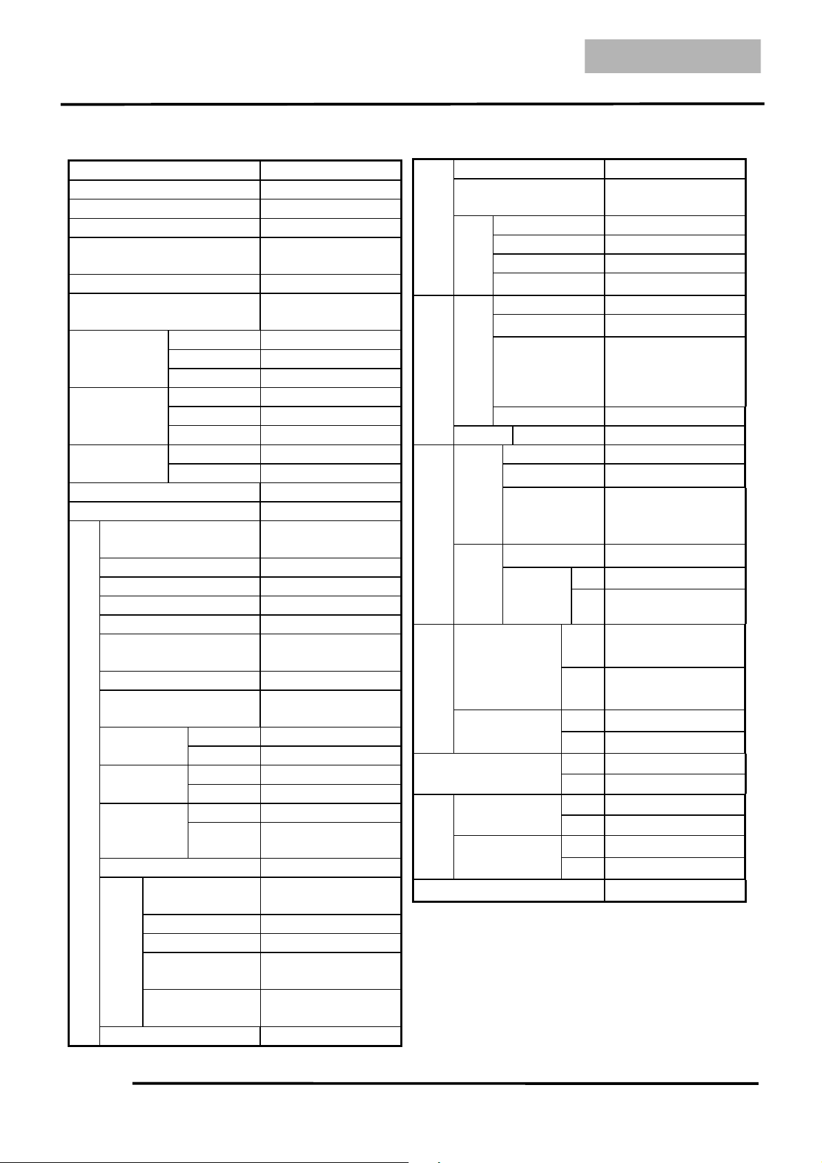
SERIAL NUMBER-----------------------------------------------------------1 - 1
SPECIFICATION (DINK 200i) -------------------------------------------- 1 - 2
SPECIFICATION (DINK 125) --------------------------------------------- 1 - 3
SERVICE PRECAUTIONS ------------------------------------------------- 1 - 4
TORQUE VALUES ---------------------------------------------------------- 1 - 8
SPECIAL TOOLS ------------------------------------------------------------1-11
LUBRICATION POINTS --------------------------------------------------- 1-13
CABLE & HARNESS ROUTING--------------------------------------------1-15
TROUBLESHOOTING (DINK 200i) ------------------------------------- 1-31
TROUBLESHOOTING (DINK 125) -------------------------------------- 1-42
1
1. GENERAL INFORMATION
1-1
DINK200i/125
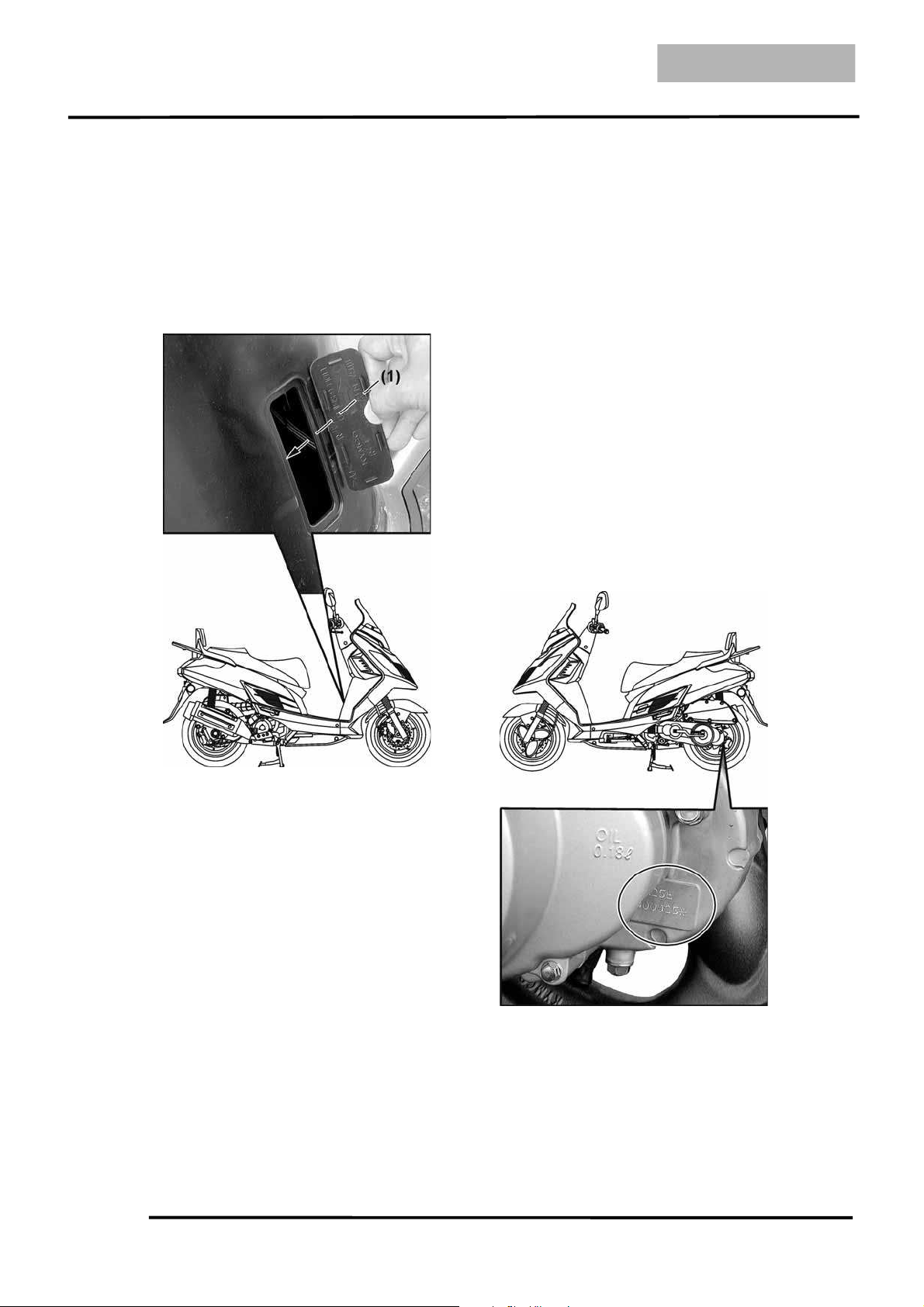
SERIAL NUMBER
Location of Engine Serial Numbe
r
(1) Location of Frame Serial Numbe
r
1. GENERAL INFORMATION
1-2
DINK 200i/125
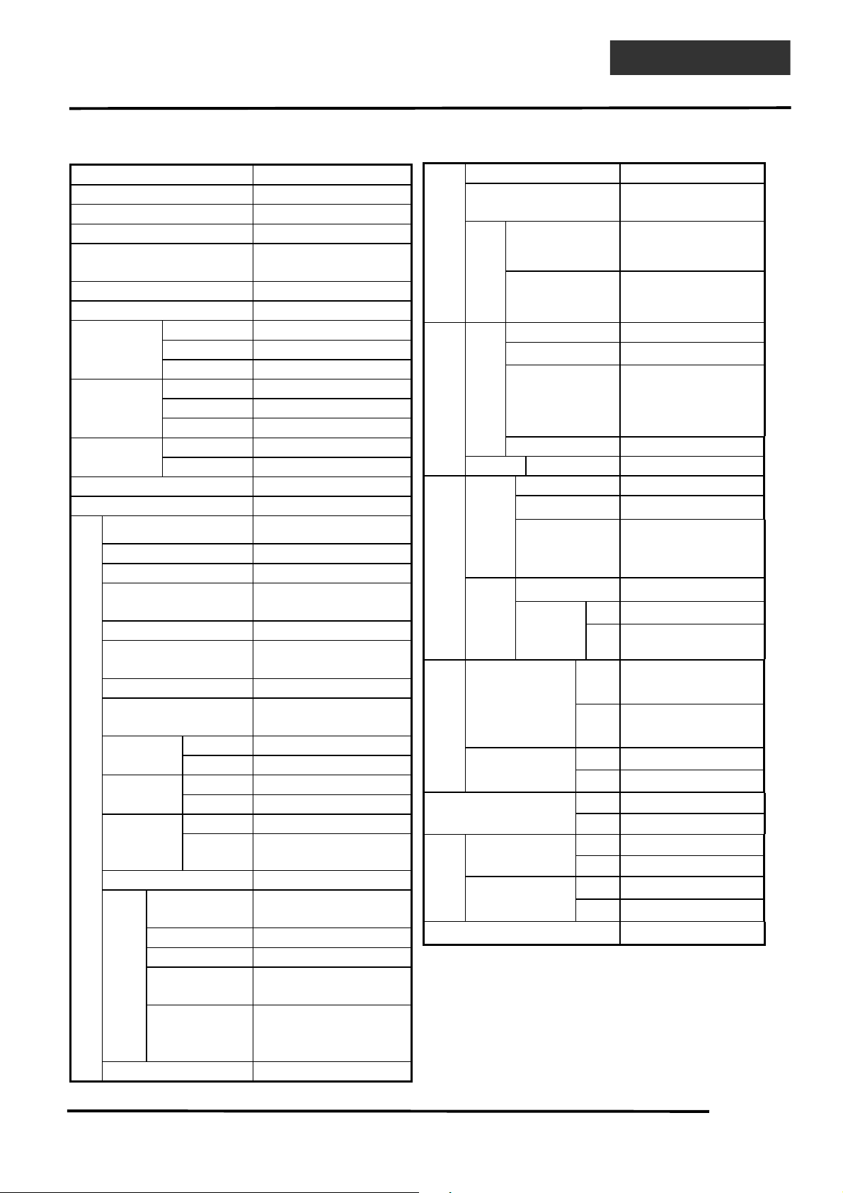
SPECIFICATIONS (DINK 200i)
Overall length 2030 mm (81.2 in)
Overall width 780 mm (31.2 in)
Overall height 1255 mm (50.2 in)
Wheel base 1390 mm (55.6 in)
Engine type
Water cooled 4-stroke,
OHC engine
Displacement 174.5 cc (10.48 cu-in)
Fuel Used 92# nonleaded gasoline
Front wheel 58 kg (127.6 lb)
Rear wheel 82 kg (180.4 lb)
Dry weight
Total 140 (308 lb)
Front wheel 65 kg (143 lb)
Rear wheel 89 kg (195.8 lb)
Curb weight
Total 154 kg (338.8 lb)
Front wheel 120/70-13
Tire
Rear wheel 140/70-12
Ground clearance 140 mm (308 in)
Min. turning radius 2350 mm (94 in)
Starting system
Starting motor
Type Gasoline, 4-stroke
Cylinder arrangement Single cylinder
Combustion chamber
type
Semi-sphere
Valve arrangement O.H.C.
Bore x stroke 62×57.8 mm
(2.48×2.312 in)
Compression ratio 11.2:1
Compression pressure
16 kgf/cm
2
(1600 kPa,
227.2 psi)
Open 12 (BTDC)
Intake
Close 35 (ABDC)
Open 28 (BBDC)
Exhaust
Close 8 (ATDC)
Intake 0.1 mm (0.004 in)Valve
clearance
(cold)
Exhaust 0.1 mm (0.004 in)
Idle speed (rpm) 1660±100rpm
Lubrication
type
Forced pressure &
Wet sump
Oil pump type Inner/outer rotor type
Oil filter type Full-flow filtration
Oil capacity
1.1 L (0.968 lmp qt,
1.166 US qt))
Lubrication System
Oil
exchanging
capacity
0.9 L (0.792 lmp qt,
0.954 US qt)
ENGINE
Cooling Type Liquid cooled
Air cleaner type Paper element, wet
Fuel capacity
11 L (2.31 lmp gal,
2.86 US gal)
Type
Programmed fuel
injection
Fuel System
Carburetion
Throttle bore !28 mm (!1.12 in)
Type ECU
Ignition timing ECU control
Spark plug
NGK
DPR6EA-9
Ignition System
Spark plug gap 0.9 mm (0.036 in)
Electrical Equipment
Battery Capacity 12V10AH
Clutch type Dry multi-disc clutch
Type Non-stage transmission
Transmission
Gear
Operation
Automatic centrifugal
Type
Type Two-stage reduction
1st
2.7~0.8
Power Drive System
Reduction
Gear
Reduction
ratio
Final
8.48
Front
1.75 kgf/cm
2
(175 kPa,
24.85 psi)
Tire pressure
Rear
2 kgf/cm2 (200 kPa,
28.4
psi)
Turning Left 42.5
Moving Device
angle
Right 42.5
FrontDisk brake
Brake system
type
Rear Disk brake
Suspension
Fron
t
Telescope
type
Rear Double swing
Shock absorbe
r
Front Telescope
Damping
Device
type
Rear
Double swing
Frame type Under bone
1. GENERAL INFORMATION
1-3
DINK200i/125
SPECIFICATIONS (DINK 125)
Overall length 2030 mm (81.2 in)
Overall width 760 mm (30.4 in)
Overall height 1255 mm (50.2 in)
Wheel base 1390 mm (55.6 in)
Engine type
Water cooled 4-stroke,
OHC engine
Displacement 124.6 cc (7.6 cu-in)
Fuel Used 92# nonleaded
gasoline
Front wheel 53 kg (116.6 lb)
Rear wheel 85 kg (187 lb)
Dry weight
Total 138 (303.6 lb)
Front wheel 60 kg (132 lb)
Rear wheel 92 kg (202.4 lb)
Curb weight
Total 152 kg (334.4 lb)
Front wheel 120/70-13
Tire
Rear wheel 140/70-12
Ground clearance 140 mm (308 in)
Min. turning radius 2350 mm (94 in)
Starting system
Starting motor/Kick
starter
Type Gasoline, 4-stroke
Cylinder arrangement Single cylinder
Combustion chamber type Semi-sphere
Valve arrangement O.H.C.
Bore x stroke 52.4×57.8 mm
(2.096×2.312 in)
Compression ratio 10:1
Compression pressure
15 kgf/cm2 (1500
kPa, 213 psi)
Open 12 (BTDC)
Intake
Close 35 (ABDC)
Open 28 (BBDC)
Exhaust
Close 0 (ATDC)
Intake 0.1 mm (0.004 in)Valve
clearance
(cold)
Exhaust 0.1 mm (0.004 in)
Idle speed (rpm) 1700±150rpm
Lubrication type
Forced pressure &
Wet sump
Oil pump type Inner/outer rotor type
Oil filter type Full-flow filtration
Oil capacity
1.1 L (0.968 lmp qt,
1.166 US qt))
Lubrication System
Oil exchanging
capacity
0.9 L (0.792 lmp qt,
0.954 US qt)
ENGINE
Cooling Type Liquid cooled
Air cleaner type Paper element, wet
Fuel capacity
11 L (2.31 lmp gal,
2.86 US gal)
Type LEA5
Piston dia. !21.8 mm (!0.872 in)
Venturi dia. !24 mm (!0.96 in)
Fuel System
Carburetor
Throttle type Butterfly type
Type CDI
Ignition timing 10°±1.5°/1000 rpm
Spark plug
NGK
DPR7EA-9
Ignition System
Spark plug gap 0.9 mm (0.036 in)
Electrical Equipment
Battery Capacity 12V8AH
Clutch type Dry multi-disc clutch
Type Non-stage transmission
Transmission
Gear
Operation
Automatic centrifugal
Type
Type Two-stage reduction
1st
2.8~1
Power Drive System
Reduction
Gear
Reduction
ratio
Final
8.82
Front
1.75 kgf/cm2 (175 kPa,
24.8
5 psi)
Tire pressure
Rear
2 kgf/cm
2
(200 kPa,
28.4 psi)
Turning Left 42.5
Moving Device
angle
Right 42.5
FrontDisk brake
Brake system
type
Rear Disk brake
Suspension
Fron
t
Telescope
type
Rear Double swing
Shock absorbe
r
Front Telescope
Damping
Device
type
Rear
Double swing
Frame type Under bone
1. GENERAL INFORMATION
1-4
DINK 200i/125
SERVICE PRECAUTIONS
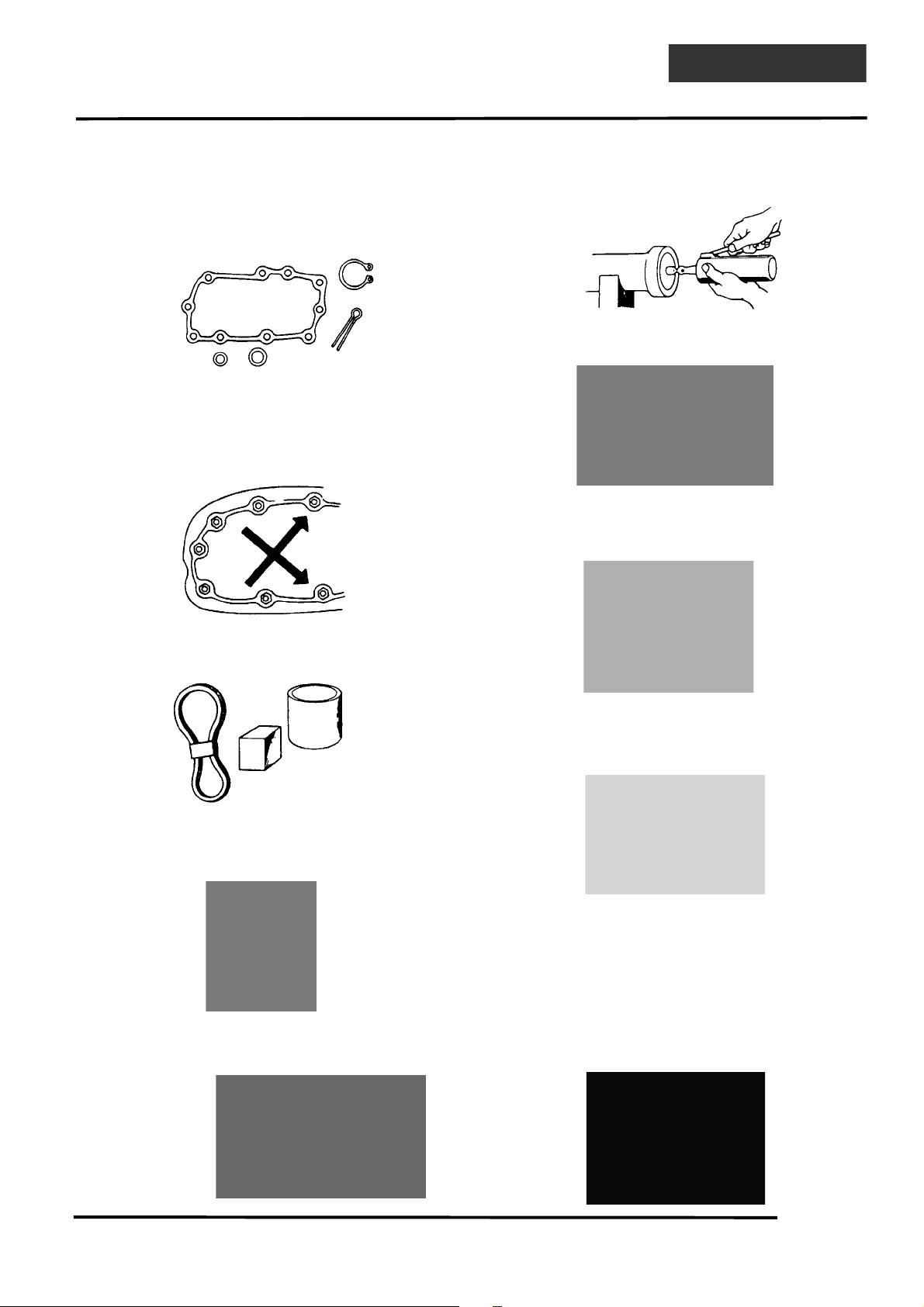
Make sure to install new gaskets, O-rings,
circlips, cotter pins, etc. when
reassembling.
When tightening bolts or nuts, begin with
larger-diameter to smaller ones at several
times, and tighten to the specified torque
diagonally.
Use genuine parts and lubricants.
When servicing the motorcycle, be sure to
use special tools for removal and
installation.
After disassembly, clean removed parts.
Lubricate sliding surfaces with engine oil
before reassembly.
Apply or add designated greases and
lubricants to the specified lubrication
points.
After reassembly, check all parts for proper
tightening and operation.
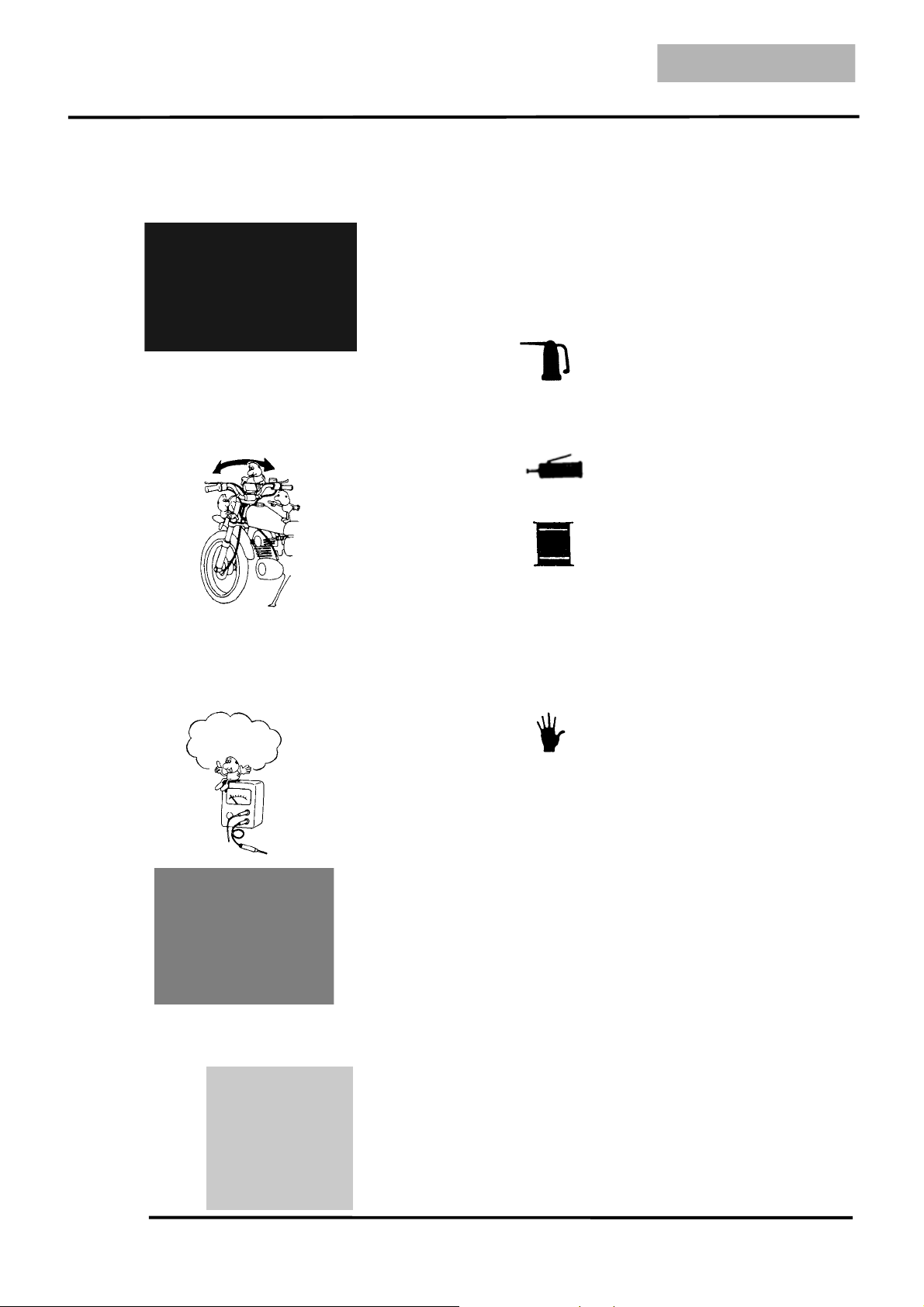
When two persons work together, pay
attention to the mutual working safety.
Disconnect the battery negative (-) terminal
before operation.
When using a spanner or other tools, make
sure not to damage the motorcycle surface.
After operation, check all connecting
points, fasteners, and lines for proper
connection and installation.
When connecting the battery, the positive
(+) terminal must be connected first.
After connection, apply grease to the
battery terminals.
Terminal caps shall be installed securely.
1. GENERAL INFORMATION
1-5
DINK200i/125
If the fuse is burned out, find the cause and
repair it. Replace it with a new one
according to the specified capacity.
After operation, terminal caps shall be
installed securely.
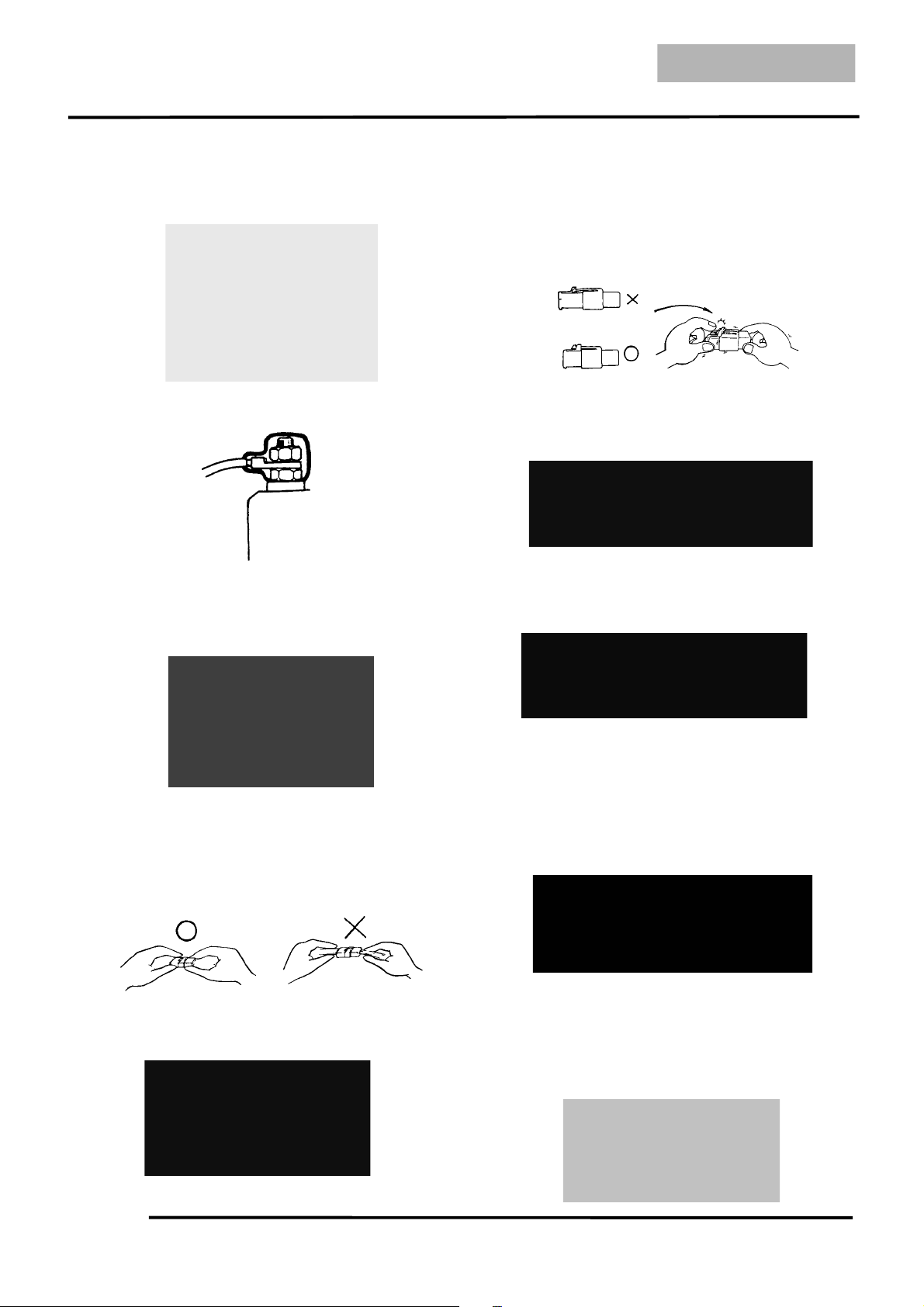
When taking out the connector, the lock on
the connector shall be released before
operation.
Hold the connector body when connecting
or disconnecting it.
Do not pull the connector wire.
Check if any connector terminal is bending,
protruding or loose.
The connector shall be inserted
completely.
If the double connector has a lock, lock
it at the correct position.
Check if there is any loose wire.
Before connecting a terminal, check for
damaged terminal cover or loose negative
terminal.
Check the double connector cover for
proper coverage and installation.
Insert the terminal completely.
Check the terminal cover for proper
coverage.
Do not make the terminal cover opening
face up.
Secure wire harnesses to the frame with
their respective wire bands at the
designated locations.
Tighten the bands so that only the insulated
surfaces contact the wire harnesses.
Confir
m
Capacity
1. GENERAL INFORMATION
1-6
DINK 200i/125
After clamping, check each wire to make
sure it is secure.
Do not squeeze wires against the weld or
its clamp.
After clamping, check each harness to
make sure that it is not interfering with any
moving or sliding parts.
When fixing the wire harnesses, do not
make it contact the parts which will
generate high heat.
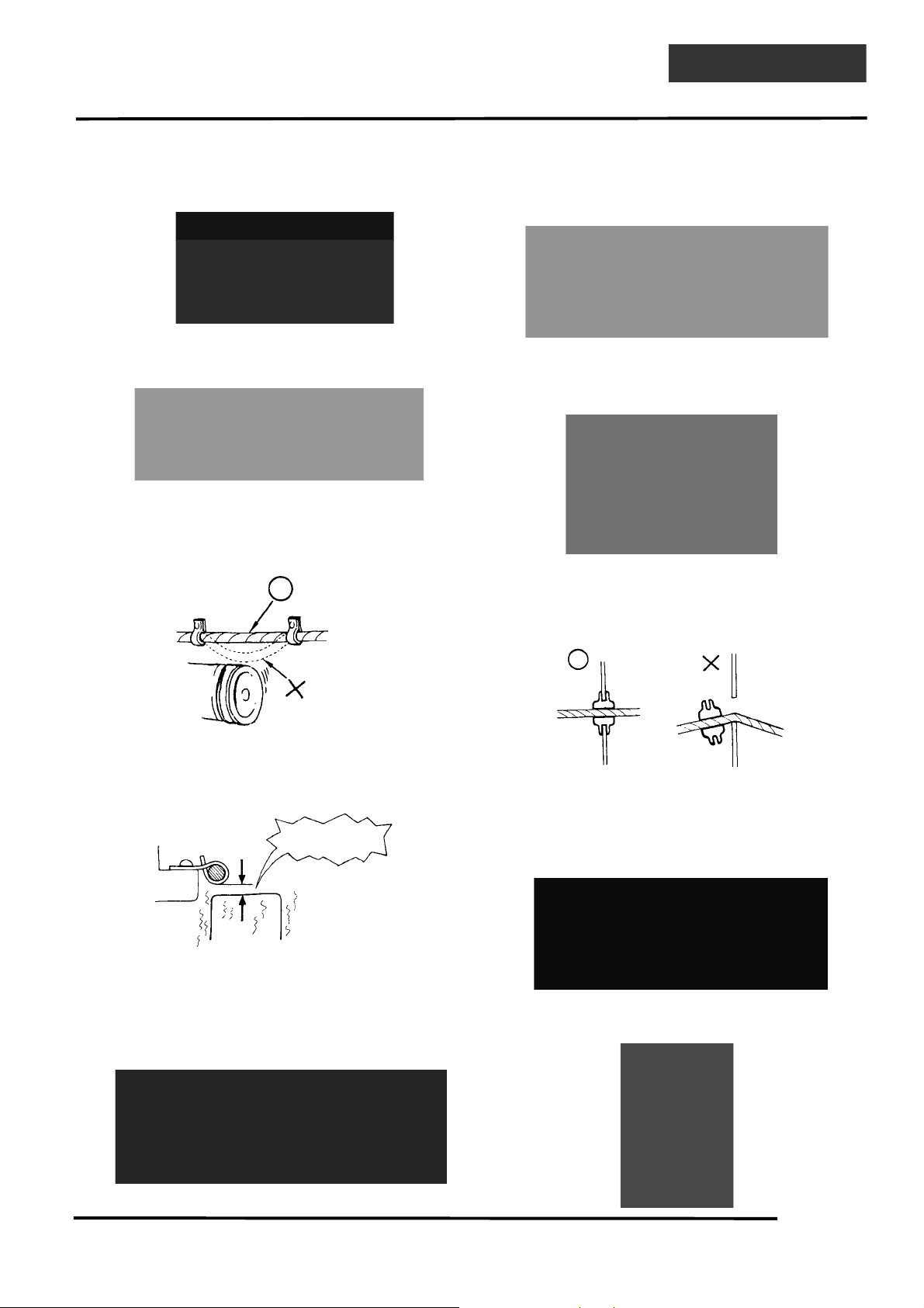
Route wire harnesses to avoid sharp edges
or corners. Avoid the projected ends of
bolts and screws.
Route wire harnesses passing through the
side of bolts and screws. Avoid the
projected ends of bolts and screws.
Route harnesses so they are neither
pulled tight nor have excessive slack.
Protect wires and harnesses with electrical
tape or tube if they contact a sharp edge or
corner.
When rubber protecting cover is used to
protect the wire harnesses, it shall be
installed securely.
Do not break the sheath of wire.
If a wire or harness is with a broken sheath,
repair by wrapping it with protective tape
or replace it.
When installing other parts, do not press or
squeeze the wires.
Do not pull
too tight• •
N
o Contac
t
Do not press or
squeeze the wire
1. GENERAL INFORMATION
1-7
DINK200i/125
After routing, check that the wire harnesses
are not twisted or kinked.
Wire harnesses routed along with
handlebar should not be pulled tight, have
excessive slack or interfere with adjacent
or surrounding parts in all steering
positions.
When a testing device is used, make sure to
understand the operating methods
thoroughly and operate according to the
operating instructions.
Be careful not to drop any parts.
When rust is found on a terminal, remove
the rust with sand paper or equivalent
before connecting.
Symbols:
The following symbols represent the
servicing methods and cautions included in
this service manual.
: Apply engine oil to the
specified points. (Use
designated engine oil for
lubrication.)
: Apply grease for lubrication.
: Transmission Gear Oil (90#)
: Caution
: Warning
Engine Oil
Grease
Gear Oil
•
•
Remove Rust• •
Do you understand
the instrument• •
1. GENERAL INFORMATION
1-8
DINK 200i/125
TORQUE VALUES
STANDARD TORQUE VALUES
Item
Torque
kgf-m (N-m, lbf-ft)
Item
Torque
kgf-m (N-m, lbf-ft)
5mm bolt and nut
6mm bolt and nut
8mm bolt and nut
10mm bolt and nut
12mm bolt and nut
14mm bolt and nut
0.5 (5, 3.6)
1 (10, 7.2)
2.2 (22, 16)
3.5 (35, 25)
5.5 (55, 40)
7 (70, 50)
4mm screw
5mm screw
6mm screw, SH bolt
6mm flange bolt and nut
8mm flange bolt and nut
10mm flange bolt and nut
0.3 (3, 2.2)
0.4 (4, 2.9)
0.9 (9, 6.5)
1.2 (12, 9)
2.7 (27, 20)
4 (40, 29)
Torque specifications listed below are for important fasteners.
ENGINE
Item Q‘ty
Thread dia.
(mm)
Torque
k
gf-m
(
N-m,
lbf-ft)
Remarks
MAINTENANCE:
Spark plug
Tappet ADJ nut
Engine oil strainer screen cap
Engine oil filter cap bolt
Engine oil drain plug
Transmission gear oil drain bolt
Transmission gear oil fill bolt
LUBRICATION SYSTEM:
Oil pump screw
COOLING SYSTEM:
Fan motor bolt
Fan motor switch
Water pump impeller
CYLINDER HEAD:
Cylinder head cover
Cylinder head nut (DINK 200i)
Cylinder head nut (DINK 125)
Tensioner sealing bolt
Cam chain tensioner mounting bolt
Cylinder head bolt
1
2
1
3
1
1
1
1
3
1
1
4
4
1
2
2
10
5
30
6
12
10
10
3
5
16
8
6
8
8
6
6
6
1.2 (12, 8.6)
0.9 (9, 6.5)
1.5 (15, 11)
1.2 (12, 8.6)
2.5 (25, 18)
1.3 (13, 9)
1.3 (13, 9)
0.2 (2, 1.5)
0.53 (5, 2.8)
1.8 (17, 13)
1.2 (12, 9)
1.2 (12, 8.6)
2.3 (23, 16.6)
2 (20, 14)
0.6 (6, 4)
1.2 (12, 8.6)
1 (10, 7.2)
Apply oil
Apply oil
Left hand threads
Apply oil
Apply oil
(Cont’d)

1. GENERAL INFORMATION
1-9
DINK200i/125
Item Q‘ty
Thread dia.
(mm)
Torque
kgf-m (N-m, lbf-ft)
Remarks
CYLINDER:
Cylinder bolt
DRIVE/DRIVEN PULLEY:
L crankcase cover
Drive pulley nut (DINK 200i)
Drive pulley nut (DINK 125)
Clutch outer nut
Driven pulley assembly plate nut
STARTER SYSTEM:
Flywheel nut
TRANSMISSION:
Transmission case cover bolt
2
8
1
1
1
1
1
9
6
6
12
10
12
28
14
6
1 (10, 7.2)
1.2 (12, 8.6)
5.8 (58, 42)
5.5 (55, 40)
5.5 (55, 40)
5.5 (55, 40)
5.5 (55, 40)
1.2 (12, 8.6)
FRAME
Item Q‘ty
Thread dia.
(mm)
Torque
k
gf-m
(
N-m, lbf-ft
)
Remarks
EXHAUST MUFFLER:
Exhaust muffler mounting bolt
Exhaust pipe mounting nut
ENGINE ASSEMBLY:
Engine hanger mounting bolt
Engine mounting bolt/nut
STEERING SYSTEM:
Steering stem lock nut
Handlebar lock nut
Steering stem pinch bolt
WHEEL:
Front wheel axle nut
Rear wheel axle nut
3
2
1
1
1
1
4
1
1
10
8
12
10
27
10
8
12
16
3.3 (33, 24)
2 (20, 14)
5 (50, 36)
5 (50, 36)
8 (80, 58)
4.5 (45, 32)
3.2 (32, 23)
6 (60, 43)
12 (120, 86)
(Cont’d)
1. GENERAL INFORMATION
1-10
DINK 200i/125
Item Q‘ty
Thread dia.
(mm)
Torque
kgf-
m
(
N-m, lbf-ft
)
Remarks
SUSPENSION:
Rear shock absorber upper mount bolt
Rear shock absorber lower mount bolt
Rear fork
BRAKE:
Front caliper
Rear caliper
Brake hose oil bolt
Master cylinder holder bolt
Master cylinder reservoir cover screw
Brake caliper bleeder
OTHERS:
Start relay nut
Rear spoiler
2
2
2
2
2
4
4
4
2
2
3
10
8
8
8
8
10
6
4
5
6
8
4 (40, 29)
2.7 (27, 19)
2.7 (27, 19)
2.7 (27, 19)
3.2 (32, 23)
3.5 (35, 25)
1.2 (12, 9)
0.16 (1.6, 1)
0.6 (6, 4))
0.3 (3, 2)
1.2 (12, 9)
1. GENERAL INFORMATION
1-11
DINK200i/125
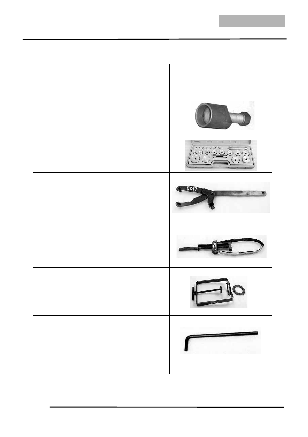
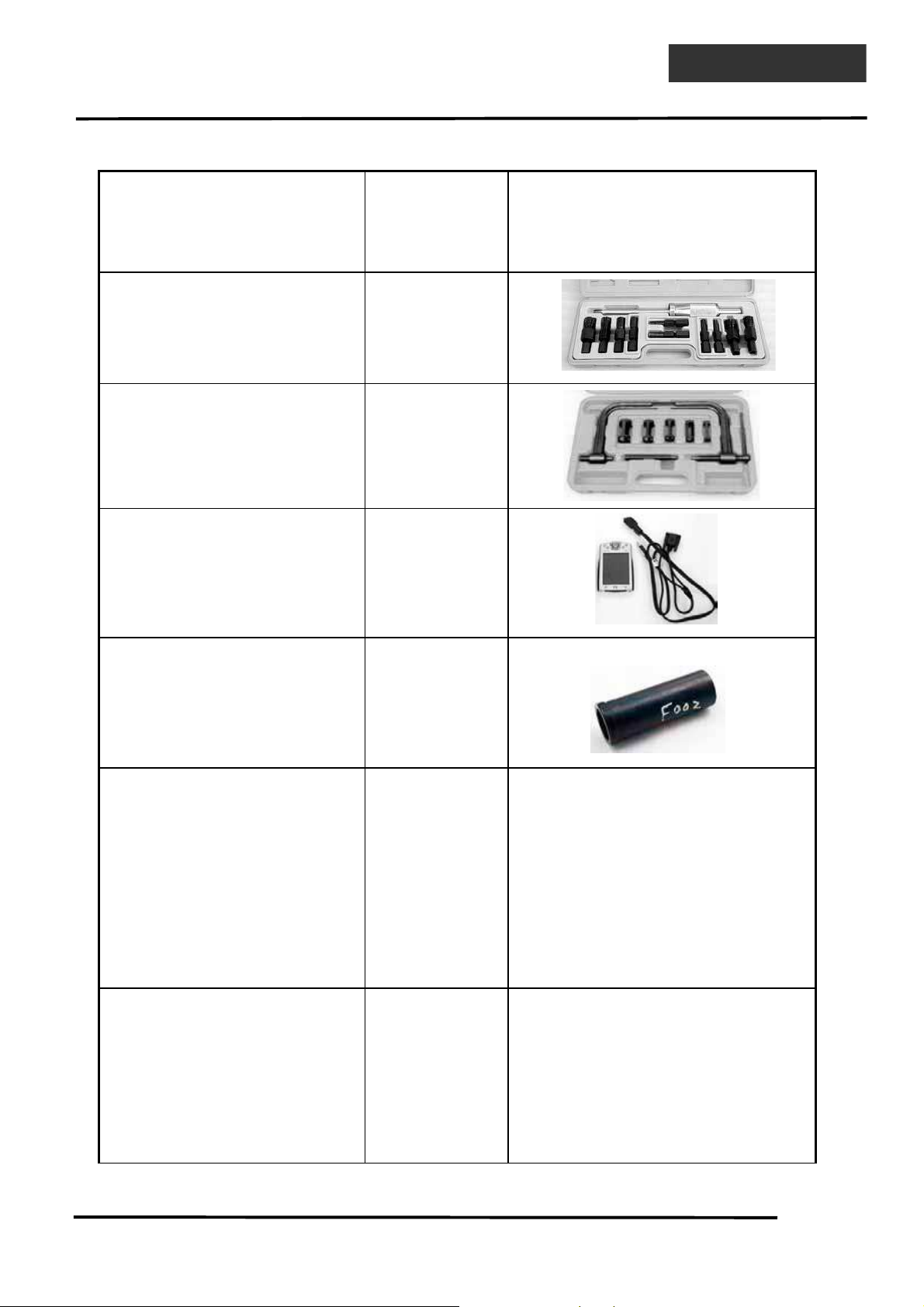
SPECIAL TOOLS
Tool Name Tool No.
Illustration
(Note: the special tools may differ
slightly from those shown in the
figure of this manual.)
Flywheel puller
(Refer to the “STARTER
CLUTCH” section in the chapter
10.)
A120E00003
Oil seal and bearing
installer
A120E00014
Universal holder
(Refer to the “DRIVE PULLEY,
DRIVE BELT AND DRIVEN
PULLEY” section in the chapter
8.)
A120E00017
Flywheel holder
(Refer to the “STARTER
CLUTCH” section in the chapter
10.)
A120E00021
Clutch spring compressor
(Refer to the “DRIVE PULLEY,
DRIVE BELT AND DRIVEN
PULLEY” section in the chapter
8.)
A120E00034
Valve adjuster
(Refer to the “VALVE
CLEARANCE” section in the
chapter 3.)
A120E00036
(Cont’d)
1. GENERAL INFORMATION
1-12
DINK 200i/125
Tool Name Tool No.
Illustration
(Note: the special tools may differ
slightly from those shown in the
figure of this manual.)
Bearing puller A120E00037
Valve spring compressor
(Refer to the “CYLINDER
HEAD” section in the chapter 6.)
A120E00040
AFI diagnostic tool pda
(Refer to the “SELFDIAGNOSTIC PROCEDURES
USING DIAGNOSTIC TOOL
(
PDA)” section in the chapter 14.
)
A120E00069
Lock nut wrench
(Refer to the “STEERING
STEM” section in the chapter 15.)
A120F00002
1. GENERAL INFORMATION
1-13
DINK200i/125
LUBRICATION POINTS
ENGINE
Lubrication Points Lubricant
Valve guide/valve stem movable part
Camshaft protruding surface
Valve rocker arm friction surface
Camshaft drive chain
Cylinder lock bolt and nut
Piston surroundings and piston ring grooves
Piston pin surroundings
Cylinder inside wall
Connecting rod/piston pin hole
Connecting rod big end
Crankshaft
Cranksahft one-way clutch movable part
Oil pump drive chain
Starter reduction gear engaging part
Countershaft gear engaging part
Final gear engaging part
Bearing movable part
O-ring face
Oil seal lip
Genuine KYMCO Engine Oil (SAE 10W-
30)
API SG Egnine Oil
Transmission gear SAE 90
Kick starter part
Friction spring movable part/shaft movable part
Final gear shaft grooved part
High-temperature resistant grease
Starter one-way clutch threads Thread locking agent
A.C. generator connector
Transmission case breather tube
Adhesive
1. GENERAL INFORMATION
1-14
DINK 200i/125
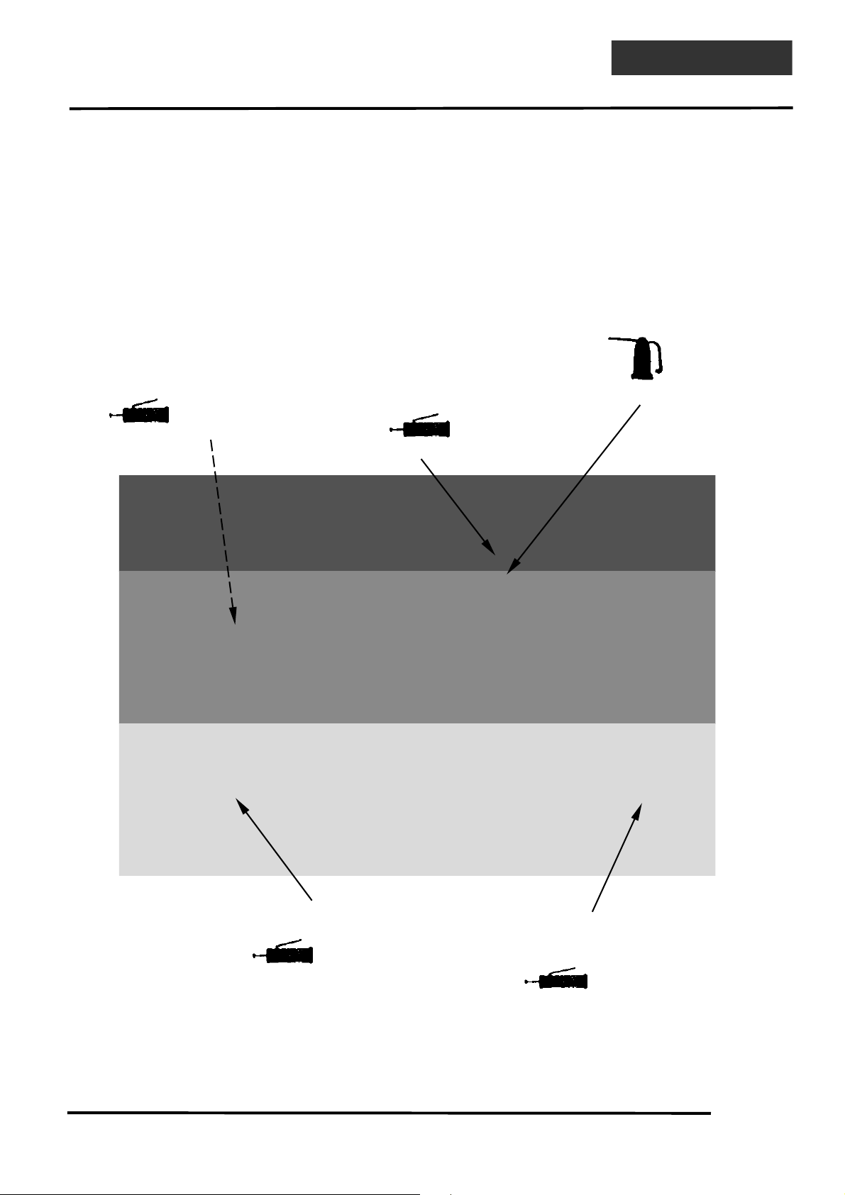
FRAME
The following is the lubrication points for the frame.
Use general purpose grease for parts not listed.
Apply clean engine oil or grease to cables and movable parts not specified. This will avoid
abnormal noise and rise the durability of the motorcycle.
Seat Lock
Grease
Engine Oil
Grease
Brake Lever Pivot
Speedometer Gear
/
Front Wheel Bearing
Grease
Rear Fork Bearing
Grease
Throttle Cable
1. GENERAL INFORMATION
1-15
DINK200i/125
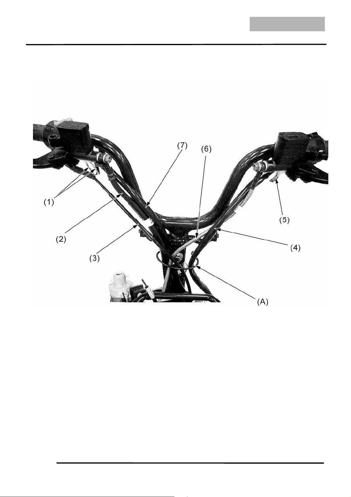
CABLE & HARNESS ROUTING
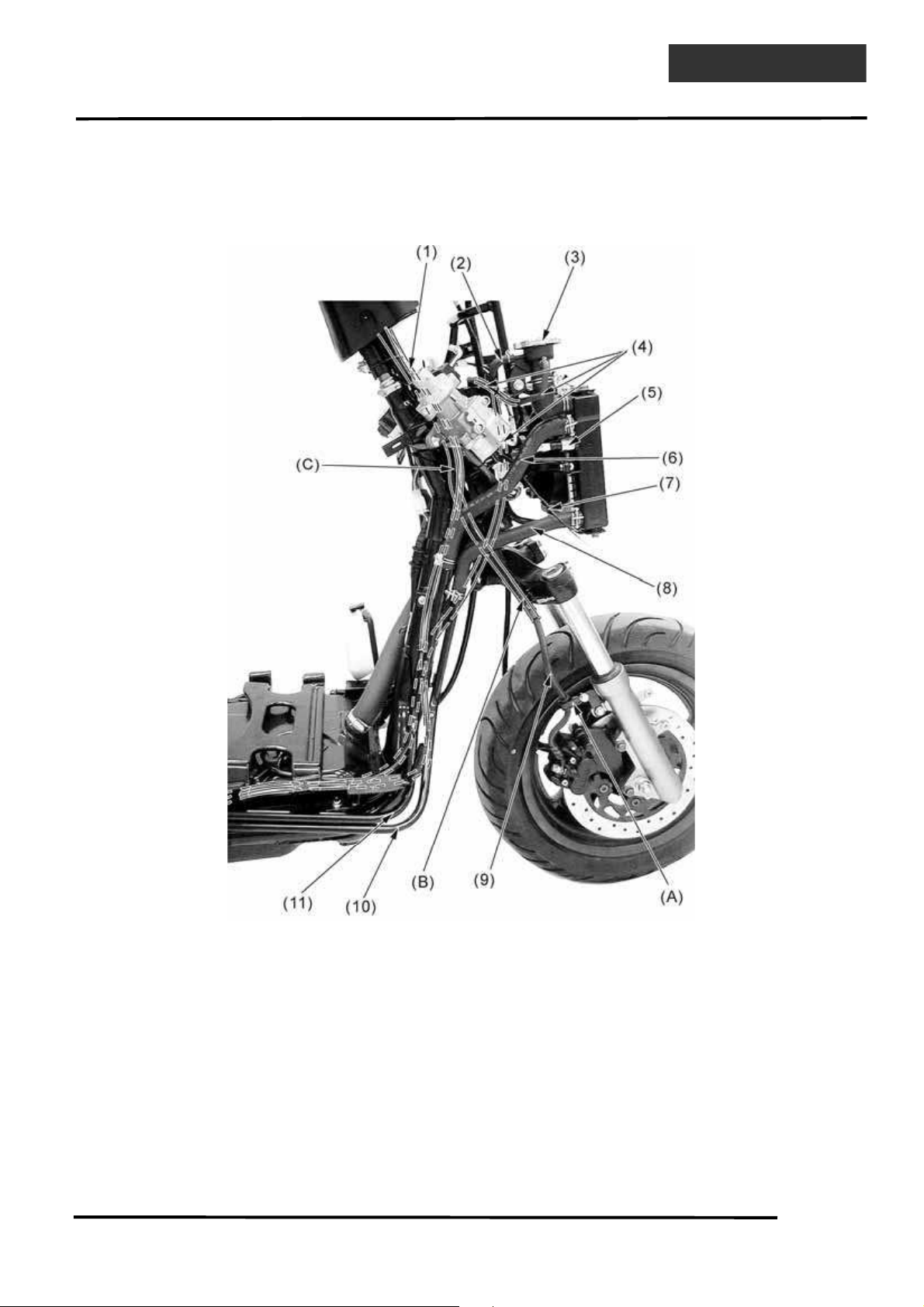
(1) Brake light switch (Front brake) (2) Front brake hose (3) Throttle cable (Note)
(4) Left handlebar switch (5) Brake light switch (Rear brake)
(6) Rear brake hose (7) Right handlebar switch
(A) Pass the front brake hose, rear brake hose, throttle cable, right handlebar switch and left handlebar
switch through the guide.
Note: Pass the throttle cable through the lower handlebar cover.
1. GENERAL INFORMATION
1-16
DINK 200i/125
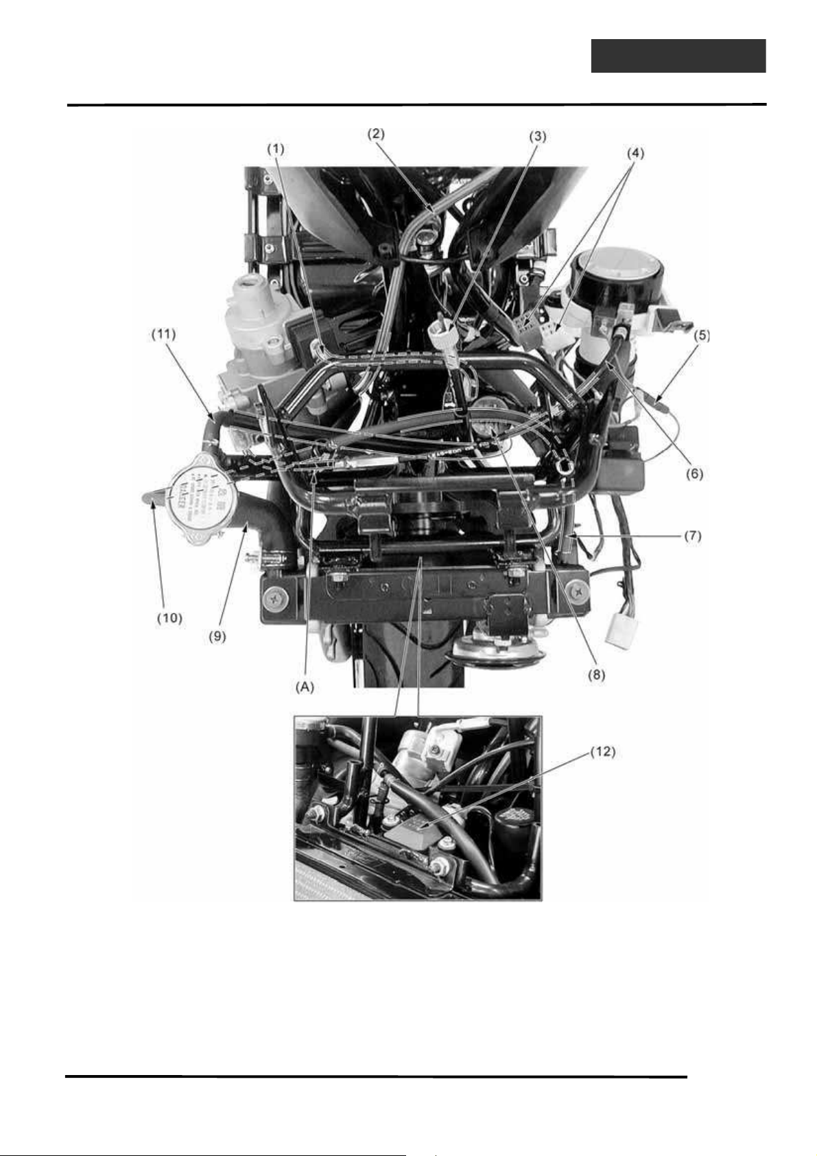
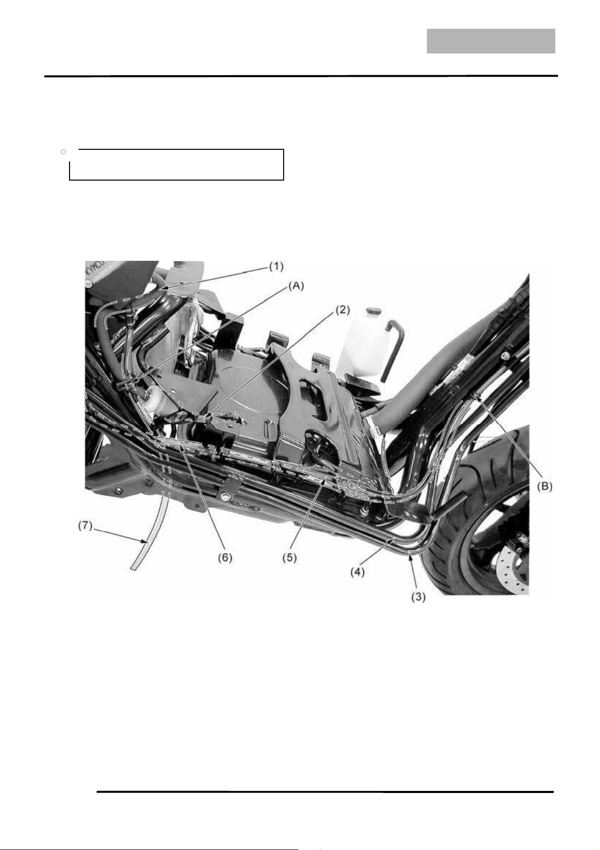
(1) Seat lock cable (2) Rear brake hose (3) Speedometer cable
(4) Instrument connectors (5) Fuel fill cap ground wire connector
(6) Fuel cap lock cable (7) Radiator bleed hose (8) Flashing relay
(9) Coolant fill hose (10) Radiator bleed hose (11) Siphon hose
(12) Angle detect sensor (DINK 200i)
(A) Pass the radiator bleed hose through the guide.
1. GENERAL INFORMATION
1-17
DINK200i/125
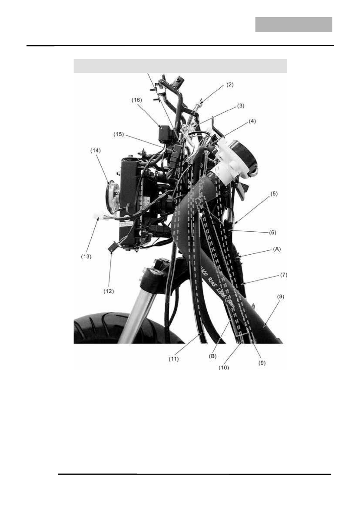
(1) Low beam relay (2) Speedometer cable (3) Resistor
(4) Fuel tank breather hose (5) Right handlebar switch (6) Left handlebar switch
(7) Harness wire (8) Fuel fill hose (9) Throttle cable
(10) Seat lock cable (11) Siphon hose
(12) Left turn signal light connector (13) Headlight connector (14) Horn
(15) High beam relay (16) Fan EMI filter
(A) Pass the harness wire through the guide.
(B) Pass the seat lock cable through the guide pipe.
1. GENERAL INFORMATION
1-18
DINK 200i/125
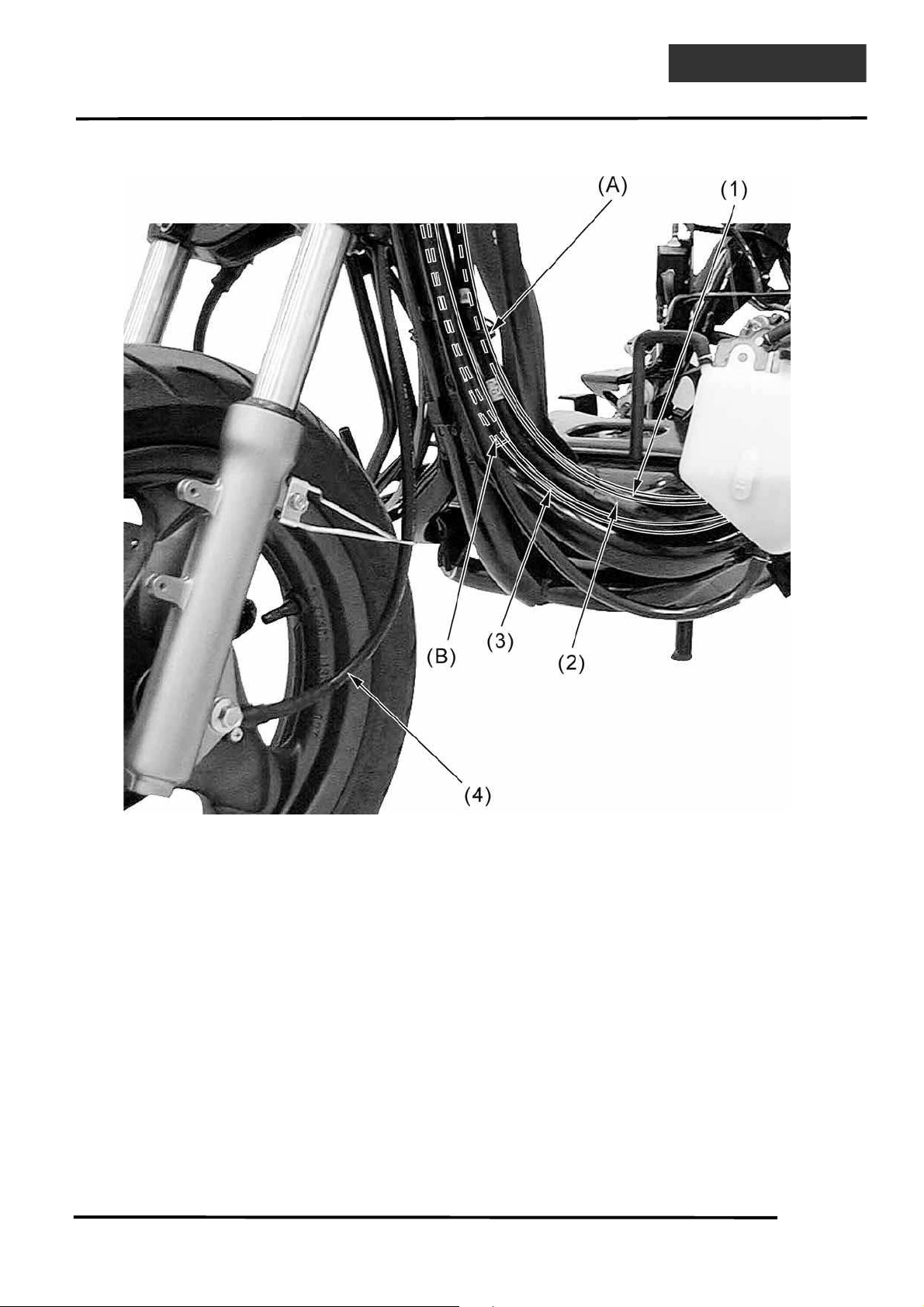
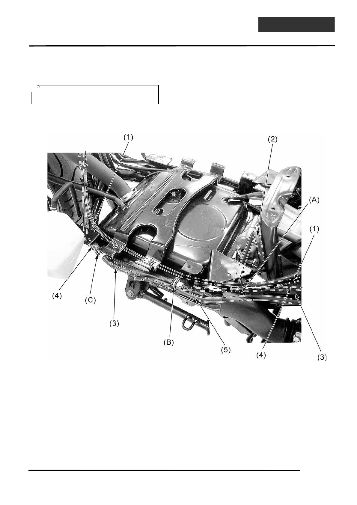
(1) Throttle cable (2) Harness wire (3) Seat lock cable
(4) Speedometer cable
(A) Pass the harness wire and throttle cable through the guide.
(B) Pass the seat lock cable through the guide pipe.
1. GENERAL INFORMATION
1-19
DINK200i/125
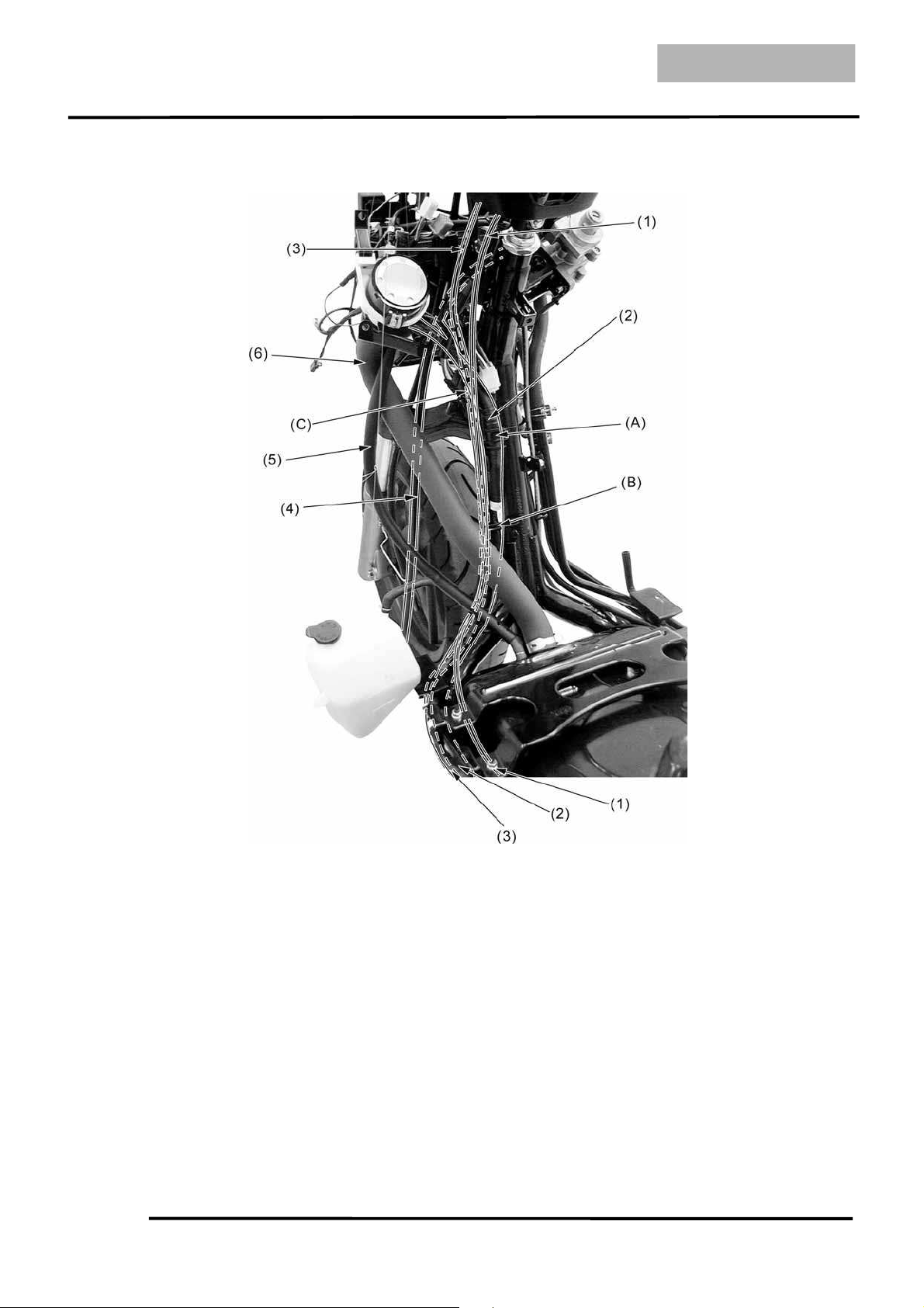
(1) Throttle cable (2) Harness wire (3) Seat lock cable
(4) Siphon hose (5) Fuel tank breather hose (6) Fuel fill hose
(A) Pass the harness wire through the guide.
(B) Pass the harness wire and throttle cable through the guide.
(C) Pass the seat lock cable through the guide pipe.
1. GENERAL INFORMATION
1-20
DINK 200i/125
(1) Throttle cable (2) AICV air inlet hose (3) Harness wire
(4) Seat lock cable (5) Side stand switch wire
(A) Pass the seat lock cable through the guide.
(B) Pass the seat lock cable and harness wire through the guide.
(C) Pass the seat lock cable and harness wire through the guide.
Refer to the page 1-30 to understand the
fuel system wire routing of DINK 200i.
• •
1. GENERAL INFORMATION
1-21
DINK200i/125
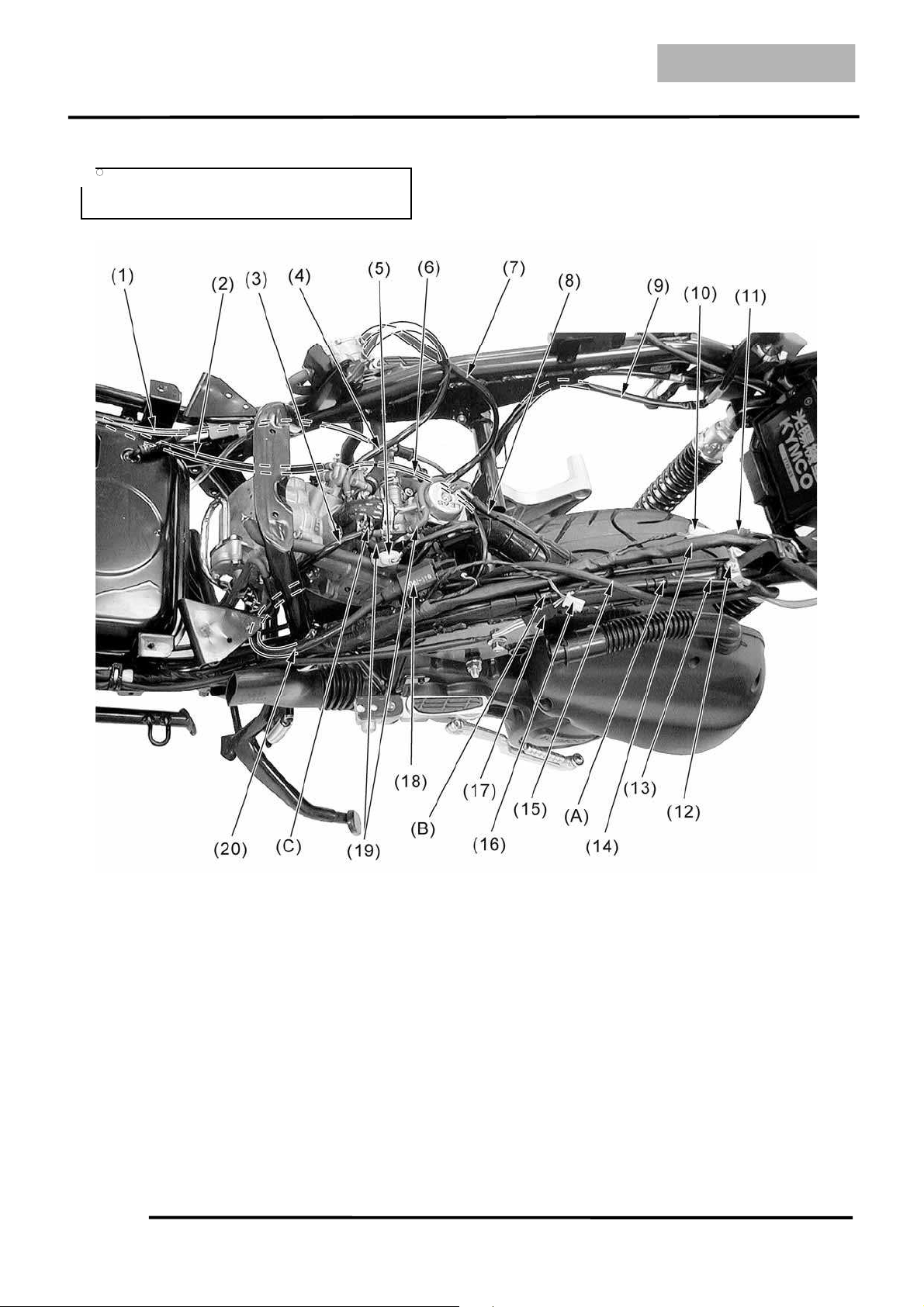
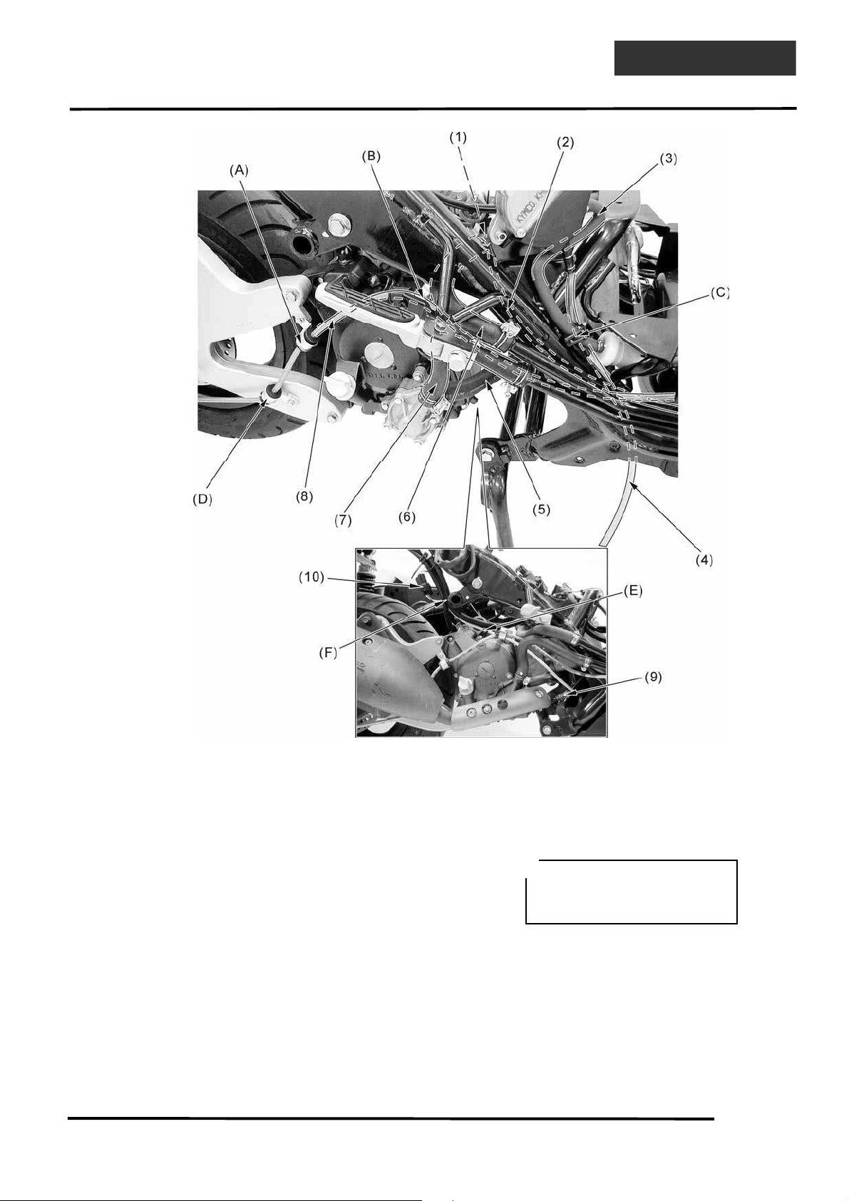
(1) Rear brake hose (2) Bleed hose (3) AICV Vacuum hose
(4) Fuel pump vacuum hose (DINK 125) (5) Carburetor heater connector (DINK 125)
(6) Coolant temperature sensor wire (DINK 125) (7) Fuel pump fuel hose (DINK 125)
(8) Throttle cable (9) Starter motor cable (10) Heater control connector (DINK 125)
(11) Auto choke connector (DINK 125) (12) Frame ground terminal
(13) Harness wire (14) Seat lock cable (15) Ground cable
(16) Luggage box light connector (17) Side stand switch connector
(18) Ignition coil (DINK 125) (19) Carburetor vacuum hose (DINK 125)
(20) Ignition coil cable
(A) Pass the seat lock cable through the guide.
(B) Pass the seat lock cable through the guide.
(C) Pass the AICV vacuum hose through the guide.
Refer to the page 1-30 to understand the
fuel system wire routing of DINK 200i.
• •
1. GENERAL INFORMATION
1-22
DINK 200i/125
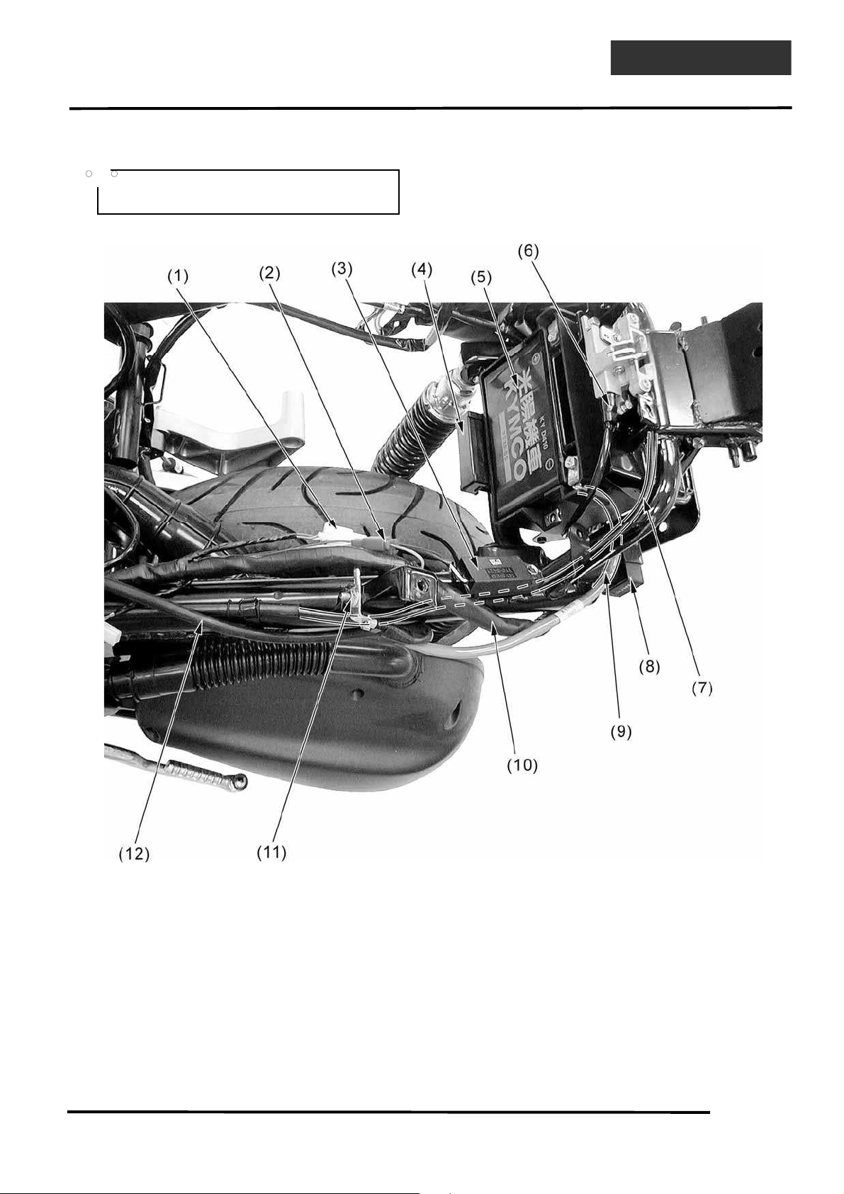
(1) Heater control connector (DINK 125)
(2) Auto choke connector (DINK 125)
(3) Heater connector (DINK 125)
(4) Fuse box (5) Battery (6) Luggage box light switch
(7) Seat lock cable (8) Engine stop control unit (DINK 200i)
(9) Battery negative cable (10) Harness wire (11) Frame ground terminal
(12) Ground cable
Refer to the page 1-30 to understand the
fuel system wire routing of DINK 200i.
• •
1. GENERAL INFORMATION
1-23
DINK200i/125
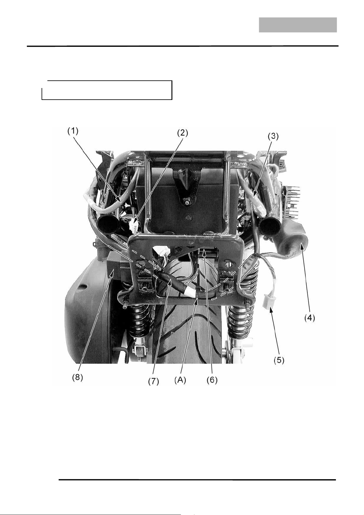
(1) Battery negative terminal (2) Luggage box light connector (3) Battery positive terminal
(4) A.C.G/Regulator/Rectifier/Starter relay connectors
(5) Combination light connector (6) Fuse box
(7) Harness (8) Engine stop control unit (DINK 200i)
(A) Pass the harness wire through the plastic band.
Refer to the page 1-30 to understand the
fuel system wire routing of DINK 200i.
• •
1. GENERAL INFORMATION
1-24
DINK 200i/125
(1) Rear brake hose (2) Siphon hose (3) Radiator cap
(4) Bleed hoses (5) Fan motor switch (6) Upper radiator hose
(7) Right turn signal light wire (8) Lower radiator hose (9) Front brake hose
(10) Lower radiator pipe (11) Upper radiator pipe
(A) Pass the front brake hose through the guide.
(B) Pass the front brake hose through the guide.
(C) Pass the front brake hose through the guide.
1. GENERAL INFORMATION
1-25
DINK200i/125
(1) DINK 125: Fuel hose (between the fuel pump and fuel filter)
(2) DINK 125: Fuel hose (between the fuel filter and fuel tank) (3) Lower radiator pipe
(4) Upper radiator pipe (5) Bleed hose (6) Rear brake hose
(7) Water flow hose
(A) Pass the fuel hose and water flow hose through the guide.
(B) Pass the bleed hose and rear brake hose through the guide.
Refer to the page 1-30 to understand the
fuel system of DINK 200i.
• •
1. GENERAL INFORMATION
1-26
DINK 200i/125
(1) Thermostat (2) Bleed hose (connect the thermostat)
(3) Fuel hose (DINK 125) (4) Water flow hose
(5) Water hose (between the water pump and cylinder)
(6) Upper radiator hose (connect the thermostat) (7) Lower radiator hose
(8) Rear brake hose (9) O2 sensor (DINK 200i)
(10) O2 sensor connector (DINK 200i)
(A) Pass the rear brake hose through the guide.
(B) Pass the rear brake hose through the guide.
(C) Pass the fuel hose (DINK 125) and water flow hose through the guide.
(D) Pass the rear brake hose through the guide.
(E) DINK 200i: Pass the O2 sensor wire through the guide
(F) DINK 200i: Pass the O2 sensor wire, harness wire, starter motor cable and A.C.G. wire
through the guide
Refer to the page 1-30 to
understand the fuel system
wire routing of DINK 200i.
• •
1. GENERAL INFORMATION
1-27
DINK200i/125
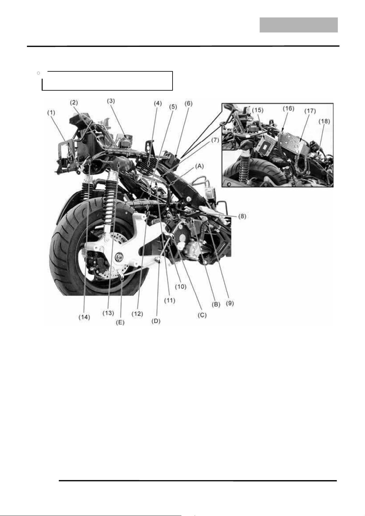
(1) Combination light connector (2) Battery positive cable
(3) Starter relay (4) Regulator/Rectifier (DINK 125)
(5) Ground cable (6) CDI (DINK 125) (7) A.C.G. wire
(8) Upper radiator hose (9) Lower radiator hose (10) Rear brake hose
(11) Starter motor cable (12) Engine ground terminal (connect the starter motor)
(13) A.C.G/Regulator/Rectifier/Starter relay connectors (14) Harness wire (DINK 125)
(15) Regulator/Rectifier (DINK 200i) (16) Harness wire (DINK 200i)
(17) ECU (DINK 200i) (18) Fuel pump relay (DINK 200i)
(A) Pass the starter motor cable and A.C.G. wire through the guide.
(B) Pass the rear brake hose through the guide.
(C) Pass the rear brake hose through the guide.
(D) Pass the rear brake hose through the guide.
(E) Pass the rear brake hose through the guide.
Refer to the page 1-30 to understand the
fuel system of DINK 200i.
• •
 Loading...