

Page 1
10.221.357 Installation and service instructions
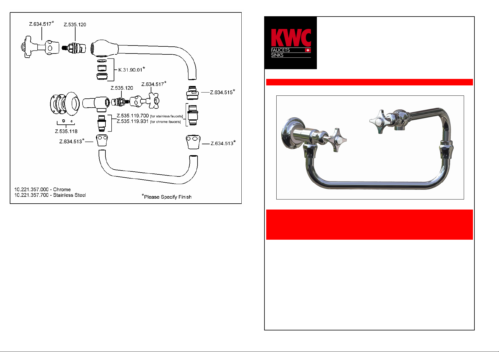
KWC 1922 Pot Filler
In General
− Faucet surface must be of room temperature before cleaning. (Warmer surfaces are
more easily damaged).
− Cleaning instructions of the manufacturer must be followed.
Maintenance
− Wipe surface dry with soft cloth daily.
− Never use aggressive or abrasive cleaners or cleaning pads.
Cleaning
− Dirt or mineral deposits on faucet’s surface should be removed with mild detergent or
soapy water.
− Rinse well immediately with cool water (make sure no detergent remains on surface).
− Dry with soft cloth.
Damage caused by improper handling is excluded from the manufacturer’s warranty.
KWC 1922 Pot Filler
KWC AMERICA INC.
1770 Corporate Drive #580
Norcross, Georgia 30093
Phone 678 334 2121
Fax 678 334 2128
www.kwcfaucets.com
KWC AG.
CH-5726 UNTERKULM,
SWITZERLAND.
Tel: 062 768 68 68
Fax: 062 768 61 62
Page 2
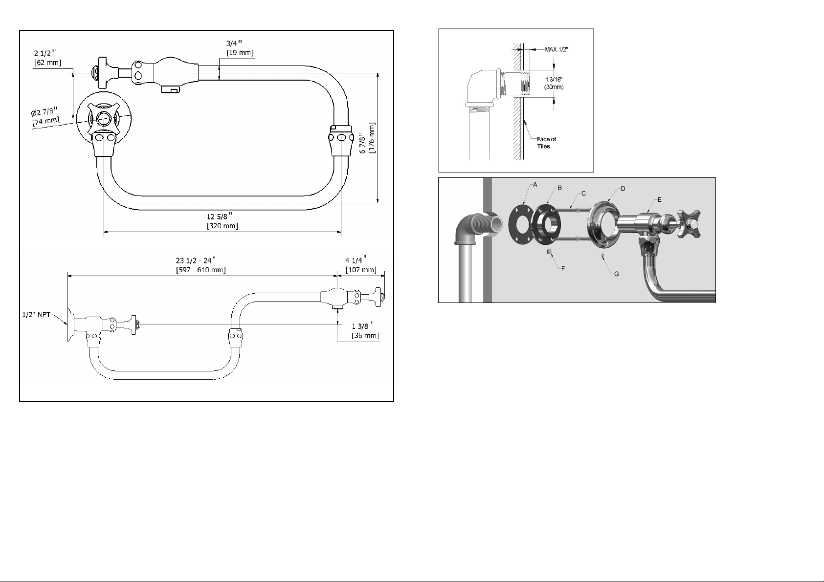
Installation
Note: When installing on plasterboard walls
(not solid walls) an appropriate reinforcement must be in place to ensure sufficient
strength.
KWC 1922 Pot Filler should be connected to
a 1/2” male NPT connector.
Arrange the in-wall plumbing so that the pot
filler is positioned at an appropriate height for
your particular installation.
Operation
Pot fillers are designed for the delivery of
cold tap water and may be positioned
above basins or stoves. The dual swivel
spout enables the outlet to be
conveniently positioned above pots/pans
Operating Data
Ideal operating pressure : 3 bar (45 PSI)
Max. operating pressure : 5 bar (70 PSI)
Ideal water temperature : 20°C (68°F)
Max. water temperature : 60°C (140°F)
as required.
For ease of use, the pot filler is fitted with
2 control valves. If the pot filler is to be
left unattended, ensure both valves
are in the closed position.
The adjustable flange allows for correct installation without the need for precise
positioning of the internal pipe work. Therefore, the NPT connector should protrude
from the wall / tile face 0 - 1/2”.
Plaster (and tile) around the 1/2” NPT connector so that the flange (D) will cover the
rough area. Ensure room is left for the valve body (E) to pass through onto the
connector and enough space is left for attachment with the screws (C) and anchors.
Thread the pot filler onto the plumbing connection with the flange back plate (B) over
the valve body (E). Without fully tightening, position and level (spirit level recommended) the pot filler horizontally, slide the flange back plate (B) up against the wall,
and tighten onto the valve body (E) with the set screw (F). Mark the position of the
holes, and remove the pot filler.
Drill the 4 holes as marked, and attach the flange back plate (B) and seal (A) to the
wall with the screws (C) provided.
Fit the flange cover (D) over the valve body (E) and attach to the connector ensuring
seal. (PTFE tape may be required). The pot filler must be tightened so that it finishes
in a horizontal position and again is fastened in place with the set screw (F).
Slide flange cover (D) over the back plate (B) and fix in place with the set screw (G).
 Loading...