

Page 1

Introducing the DMT interface
The Kurzweil DMT interface (known henceforth as the
digital audio sample-rate and format convertor, which can synchronize the
sample-rate clocks of up to four independent stereo signals. It can work with
digital audio, bidirectionally, from Kurzweil K2500-series instruments, AES/
EBU sources, S/PDIF sources using either coaxial or optical cables, and
modular digital multitrack recorders such as the Alesis ADAT and TASCAM
DA-88. It makes working with multiple digital audio formats simple.
What’s In the Box
• The
• AC power cord
• 3-meter “KDS” interface cable for connecting the
You should save the
DMTi
longer KDS interface cable—15 meters—is available from Kurzweil.)
Why Do I Need It?
Anyone who has tried to combine multiple digital audio signals while keeping
them in the digital domain knows that this can be extremely difficult. Clicks,
dropouts, speed changes, and other anomalies show up with regularity, often
with no consistency, in the result.
itself
DMTi
) is a versatile
DMTi
with a K2500. (A
DMTi
’s packaging materials, in case you ever have to ship it.
The reason for this is that the AES/EBU digital audio standard (and its
offshoot, the “consumer” or S/PDIF standard) has no provisions for externally
clocking the samples—in other words, every digital audio signal carries its
own timing information. This means that two signals from two different
sources will have no common timing reference, so when you try to combine
them, errors will occur that cause samples to be skipped or dropped,
producing various unpleasant audible artifacts.
Since the modern audio studio uses digital audio from a variety of sources,
including hard-disk audio systems, samplers, signal processors, mixers, DAT,
CD, and digital multitrack tape decks, the problem has become acute. One
common solution has been to convert all of the signals to analog before mixing
them, and thus avoid the problem of conflicting sample rates altogether. While
this is acceptable in some situations, it obviously defeats at least some of the
purpose of using digital audio in the first place.
However, if the sample-rate clocks of these sources can be coordinated so that
they are in perfect synchronization with each other while staying in the digital
domain, these problems can be avoided without resorting to analog solutions.
1User’s Guide
Page 2

What Else Do I Need?
To connect your
equipped with a KDS Output Option or KDFX Option. These options require
the K2500 to be running operating system version 2.3 or higher.
For hooking the
ate interface option installed into the
Kurzweil dealer if you have any questions.
What Does It Do?
The principle behind the
mented with some very sophisticated technology. There are four sets of digital
inputs, in three different formats, and four sets of digital outputs, also in three
formats. Each input and output comprises two channels of audio. The signal
on each input is converted, and then routed to any one (or more) of the outputs.
The conversion process can change the sample-rate clock, either to a sample
rate determined by one of the other incoming audio signals; to the rate set by
incoming word clock; or to a rate set by the
sample-rate clock is chosen serves as the master for the entire unit—therefore,
all four of the digital signals appear at the outputs in perfect synchronization
with each other.
DMTi
to a K2500 Series instrument, the K2500 will have to be
DMTi
up to an ADAT or DA-88, you’ll also need the appropri-
DMTi
. Contact your Young Chang/
DMTi
is relatively simple, although it is being imple-
DMTi
’s internal clock. Whichever
The conversion process can also change the signal format, for example, from
AES/EBU to DA-88 (TDIF-1) or ADAT, or from the K2500’s proprietary “KDS”
format to S/PDIF, or from any supported format to any other. Although the
sample-rate clocks are all linked together, the format conversions of the various
audio streams can be independent of each other, and in fact multiple types of
format conversions can take place simultaneously.
The operation of the
functions, factory settings, or other obscure features to worry about. What you
see is what you get. However, the uses to which you can put the device are
quite varied—you might think of it as the “Swiss Army knife” of digital audio
tools.
2
DMTi
is very straightforward: there are no menus, hidden
DMTi
Page 3
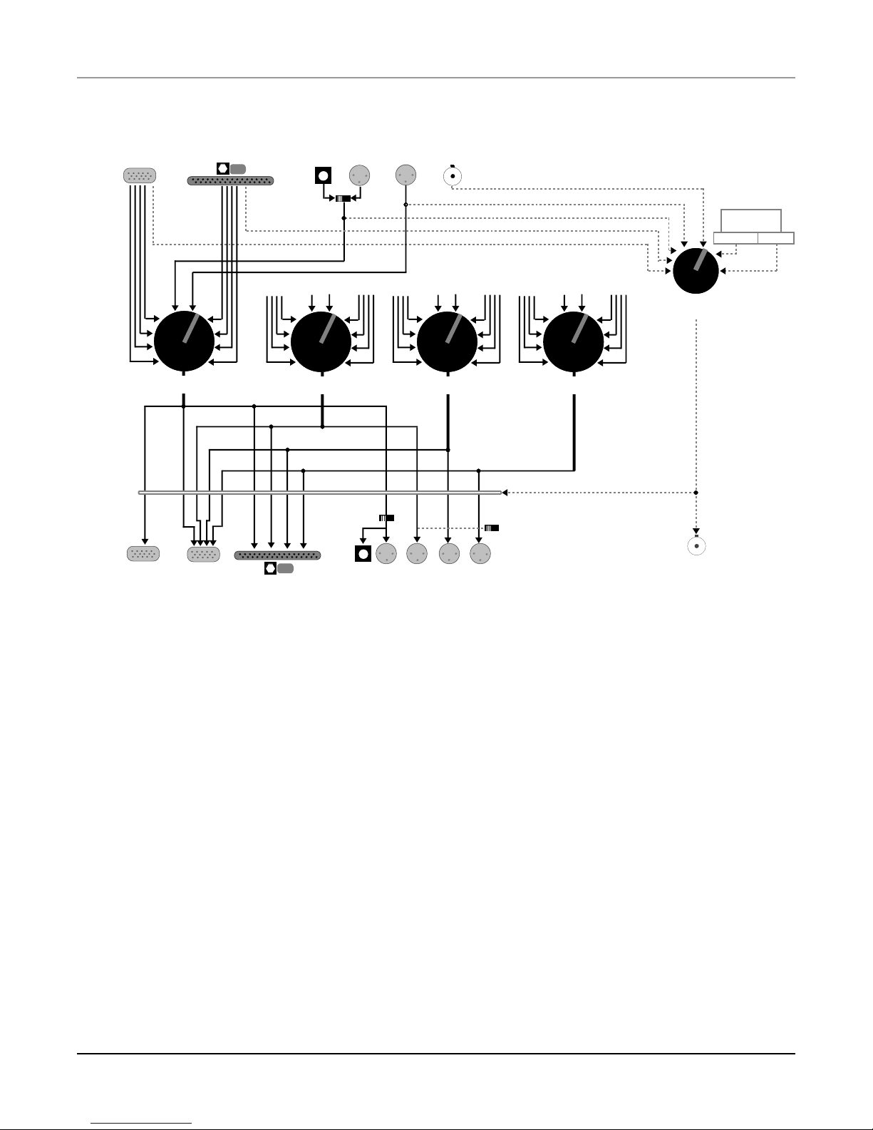
Inputs
KDS
Clock
Audio A, B, C, D
Modular Digital
Multitrack
Audio 1-2, 3-4, 5-6, 7-8
AES1
XLRoptical
Clock
Input
Select
Audio
KDS MDMAES1 AES2 KDS MDMAES1 AES2 KDS MDMAES1 AES2
Audio
AES2
Word Clock
In
Clock (derived)
Clock (derived)
44.1 kHz
Output Sync Clock
Select
Internal sample
rate generator
48 kHz
Outputs
KDS In
Return
Destination 1
ABCD
KDS Out
1-2 3-4 5-6 7-8
MDM
Destination 2 Destination 3 Destination 4
Output Format
Select (1)
XLRoptical
AES1
DMTi
AES3 AES4
AES2
signal flow
Output Format
Select (2-4)
Master Sample-rate Clock
Word
Clock Out
About This Manual
This manual starts with a description of all features and controls. After that,
we will discuss specific applications of the
the first two scenarios, even if they don’t apply to you: they will give you a
good overall idea of how to use the
easier to understand.
We don’t really expect you to read the entire manual through—each scenario is
meant to stand on its own. But besides the first two, it might be helpful to take
the time to read over all of the scenarios that might be of interest to you; the
more you understand about how the
able to form your own ideas about how to get the best out of it.
DMTi
in a variety of scenarios. Read
DMTi
, and will make the other scenarios
DMTi
can be used, the better you will be
3User’s Guide
Page 4
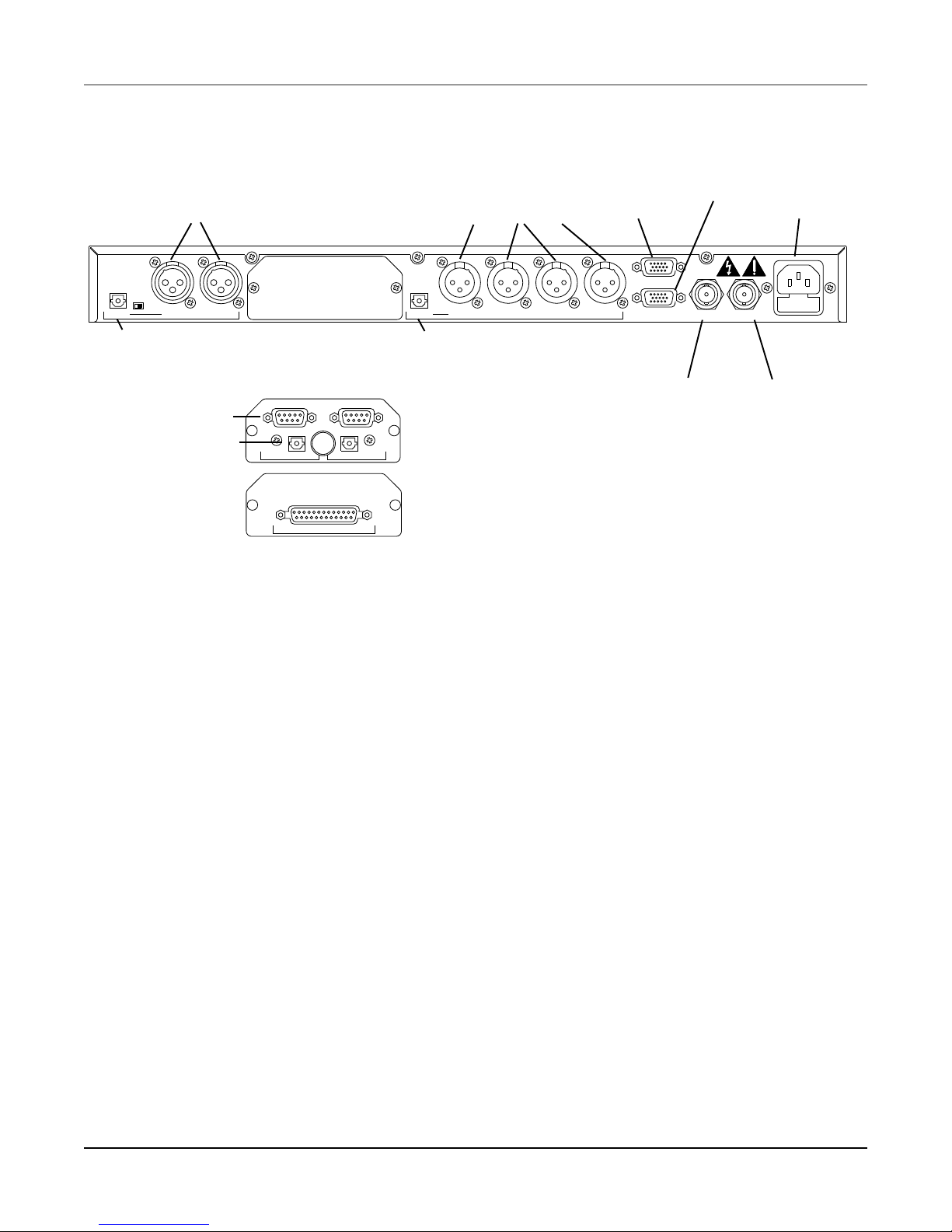
AES/EBU inputs AES/EBU outputs
Input
Select
Optical In
S/PDIF
optical
In 1AES AES In 2 Out 1
Optical Out AES AESOut 2AES Out 3 Out 4AES Word Clock In
S/PDIF optical
output
input
sync
optical (audio)
ADAT
In
ADAT
Out
ADAT interface option
KDS (K2500)
input output
(& return)
In
KDS
OutKDS
Word
Clock
input output
AC power
Word Clock Out
Inputs
TDIF-1
In/Out
DMTi
rear panel
AES1 and AES2. These two AES/EBU inputs each accept a stereo signal.
These are the “professional” type of AES/EBU connectors, as described by
the AES Type 3 specification, which use XLR connectors. These inputs can
also accept “consumer” type AES/EBU or Sony/Philips Digital Interface
Format (S/PDIF) signals, but external adapters must be used. These
adapters are described on Page 10.
The AES1 input can alternatively be accessed with an optical connector, for
S/PDIF signals in that format. A switch on the rear panel determines which
AES1 input will be active.
KDS In. This is an input for the eight-channel digital output bus (known as the
“Kurzweil Digital Stream”) from a Kurzweil 2500-series instrument which
is equipped with a KDS digital input/output or KDFX digital effects
option. It uses a 15-pin connector and a 3-meter custom cable, included
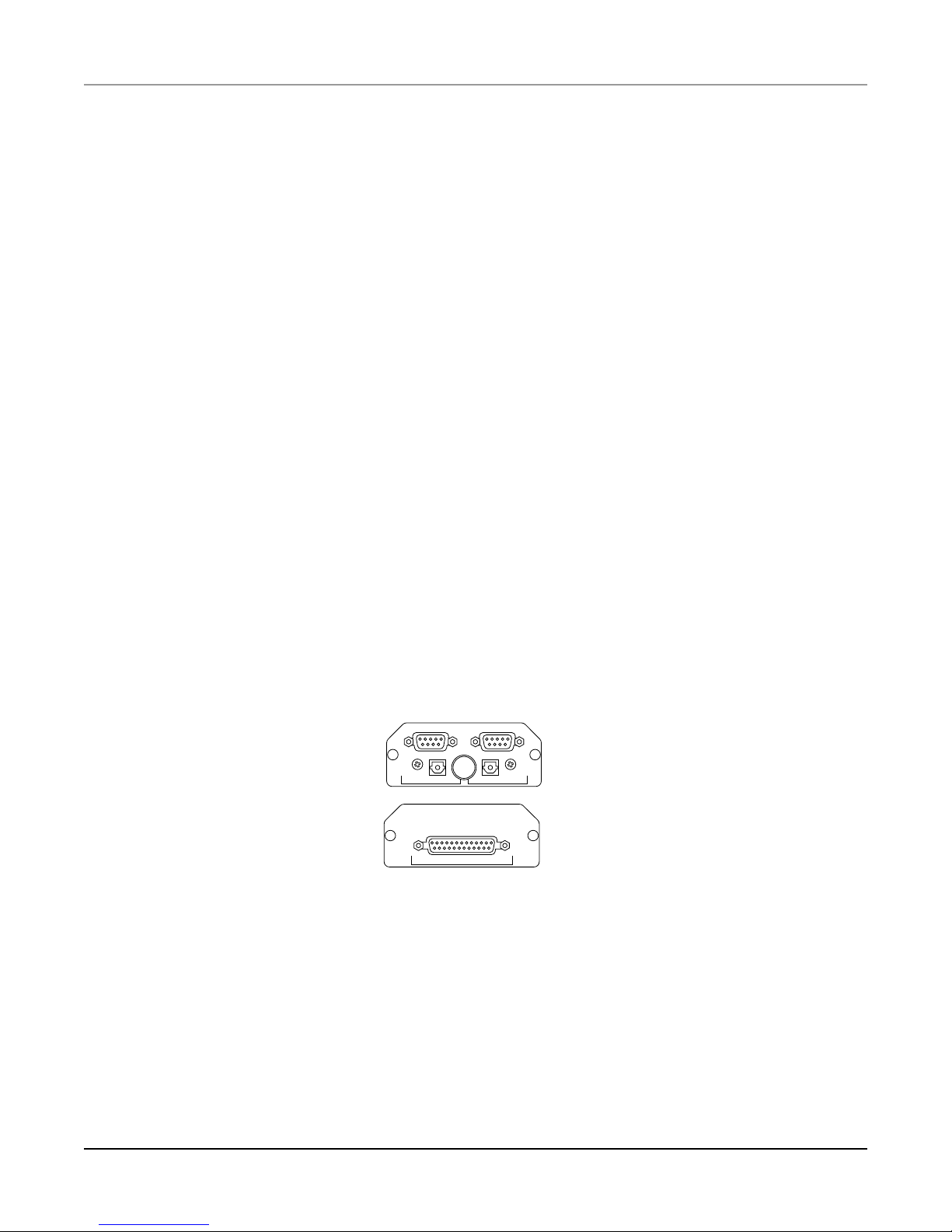
DA-88 (TDIF-1) interface option
with the
DMTi
. (A 15-meter version of the cable is available from Kurzweil
dealers.) The sampling rate of the KDS bus is 48 kHz.
The KDS In also includes a two-channel output to the K2500, called the
“Return”, which allows signals being processed through the
DMTi
to be
sampled by the K2500, if the K2500 is equipped with the Sampling option.
(To use this feature, set the following parameters on the K2500’s Sample
Page: Input to “Digital” and Src to “Rtn”.)
4
DMTi
Page 5

MDM. The
using either of two options:
The ADAT option, for use with Alesis, Fostex, and Panasonic decks, uses an
optical connnector for audio and a DB-9 connector for synchronization. The
pair labelled In is for signals from an ADAT. (Be careful not to connect the
ADAT option’s optical connectors with an AES or S/PDIF optical input or
output—you won’t damage anything, but the formats are not compatible.)
It is possible to use just the optical cable when connecting an ADAT to the
DMTi
potential synchronization problems, and it can’t do any harm. Some other
devices that use the ADAT interface, such as mixers, do not use the sync
cable.
The DA-88 (or “TDIF-1”) option, for use with TASCAM and Sony decks, uses
a single 25-pin connector which handles both input and output signals.
Word clock. This input accepts sample-rate or word clock from an external
source such as a digital audio system (with separate word clock signal) or a
synchronizer. The word clock signal is a square wave, with a frequency of
between 38 kHz and 53 kHz, at a nominal level of 5 volts peak-to-peak
(minimum 200 mV). The signal is carried on 75Ω unbalanced coaxial cable,
terminated with a BNC connector.
DMTi
can be interfaced with a Modular Digital Multitrack tape deck
, but it is not advised—using the sync cable is an easy way to avoid
Outputs
AES1, AES2, AES3, and AES4. These four outputs each carry a stereo signal.
Like the AES inputs, these are the “professional” type of AES/EBU
connectors, using XLR connectors, and they can also be used to drive
“Consumer”-type AES/EBU or Sony/Philips Digital Interface Format
(S/PDIF) inputs on other devices, with proper external adapters (see Page
10).
The AES1 output is also sent to an optical connector, for use with
compatible AES or S/PDIF devices.
Output switches on the front panel determine whether the output signals
are in “Pro” or “Consumer” format. The difference involves certain channel
status information. (There are also differences in level and impedance, but
this switch does not deal with them.) One switch controls output 1, while
the other controls outputs 2, 3, and 4.
5User’s Guide
Page 6

KDS Out. This output is designed for linking two
the
DMTi
with other KDS-compatible equipment, including any K2500
DMTi
s together, or linking
Series instrument equipped with a KDFX board. Without the KDFX board,
those instruments have only a single return input pair, and that pair is
accessed, as described on Page 4, on the KDS In jack. The KDS Out jack,
unlike the KDS In, is unidirectional, and carries only the eight output
channels being generated by the
DMTi
.
KDS In. As described on Page 4, the KDS In includes a two-channel output to
the K2500, known as the “Return”, which allows signals being processed
through the
DMTi
to be sampled with the K2500.
MDM. If you have the ADAT option, a pair of jacks, one optical and one DB-9,
labelled Out serves as the output to an ADAT-format digital multitrack
recorder or mixer. (Do not confuse the ADAT optical connector with the
AES optical connectors.) On the DA-88 (TDIF-1) option, the DB-25
connector serves as both input and output.
Note: All of the audio outputs are in parallel, and all are “live” all the time.
Therefore, a signal that is r outed to the AES1 output will also appear at the
first two channels of the MDM output (“1-2”), the first pair of the KDS Out
jack (“A”), and the “return” to the K2500 located on the KDS In jack. You
can monitor signals as they go through the
DMTi
by listening to one of the
unused outputs through an appropriate device such as a DAT.
The Word Clock Output carries a word clock signal, the source of which is
determined by the Output Sync Clock Select switch. This signal is either
derived from an incoming digital audio signal; is generated by the
DMTi
is an echo of the signal appearing at the Word Clock Input. If the switch is
set to an input at which there is no signal, then either no signal or an
unstable, unpredictable signal will appear at this output. Like the input,
this output uses a 75Ω unbalanced coaxial cable with a BNC connector.
; or
6
DMTi
Page 7
Source
outing
R
AES 1
AES 2
D
1-2
C
3-4
B
A
KDS MDM
AES 1, MDM 1-2, KDS A, KDS Rtn
5-6
7-8
Output Format
ower
P
Pro Cnsmr Pro Cnsmr
Destination 1 Destination 1 Destination 2
Source
AES 1
D
C
B
A
KDS
AES 2, MDM 3-4, KDS B
AES 2
1-2
3-4
5-6
7-8 A
MDM
Source
AES 1
AES 2
D
C
B
KDS
Destination 3 Destination 4 Destination 2-4
AES 1
1-2
D
3-4
C
5-6
B
7-8
A 7-8
MDM KDS
AES 4, MDM 7-8, KDS DAES 3, MDM 5-6, KDS C
Source
AES 2
1-2
3-4
5-6
MDM
Output Format
utput Sync Clock Select
O
AES 1
AES 2
MDM
KDS
WDCLK
Int 44.1K
Int 48K
DMT
igital
MDT
ulti-
interface
rack interface
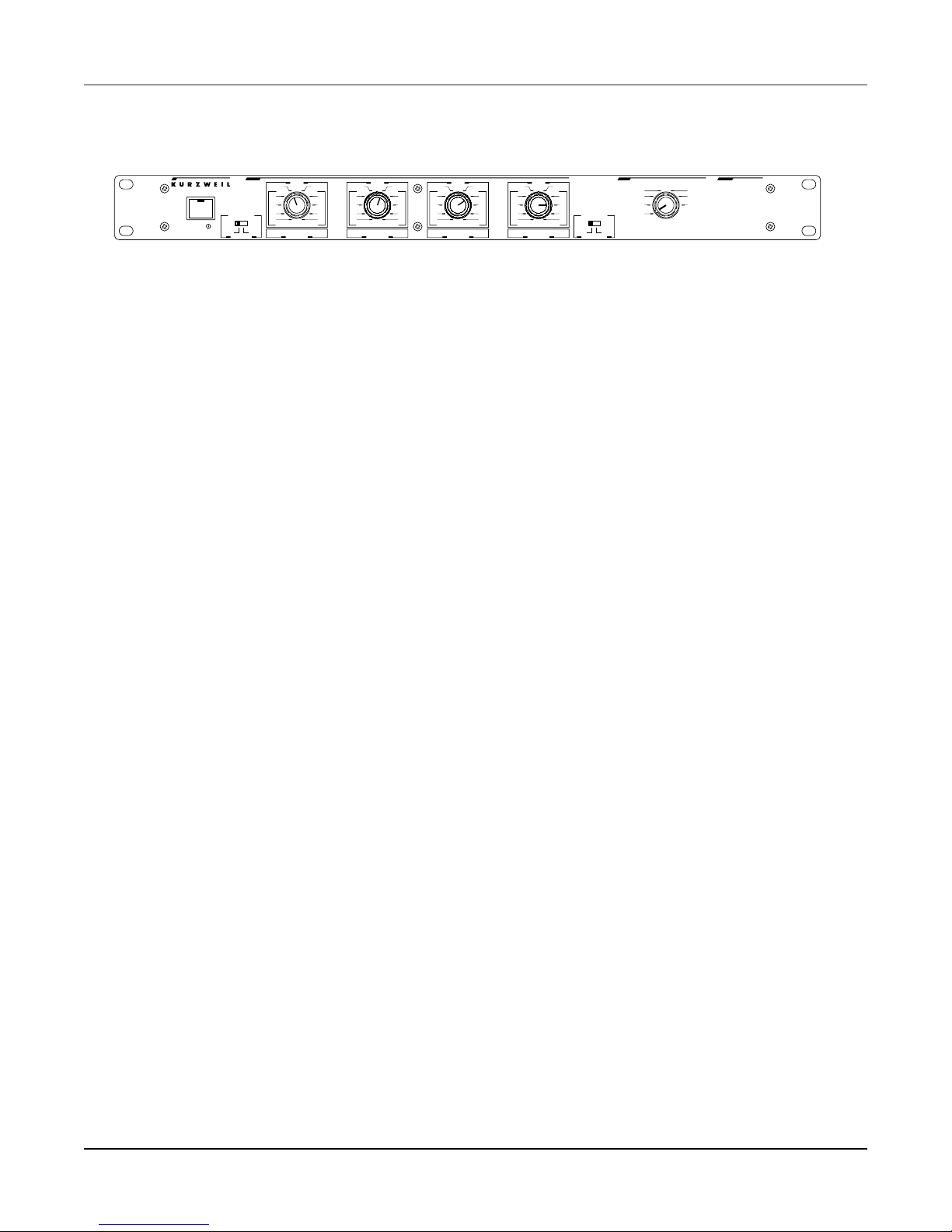
Controls and switches
The Power switch has an integral green pilot light.
The Routing section consists of the four Destination knobs, which set up the
routing of the signals. Each knob is associated with a particular output pair—it
determines which input pair will be routed to the knob’s assigned output.
The first knob selects the input source for the first pair of outputs: AES1 (both
XLR and optical), MDM “1-2”, KDS Out “A”, and the “return” pair on the
KDS In. Since the various outputs are in parallel, the setting for this knob
affects all of its associated outputs simultaneously.
The second knob sets the input source for the second pair of outputs:
AES2, MDM “3-4”, and KDS “B”.
DMTi
front panel
The third knob sets the input source for the third pair of outputs:
AES3, MDM “5-6”, and KDS “C”.
The fourth knob sets the input source for the fourth pair of outputs:
AES4, MDM “7-8”, and KDS “D”.
The choices of inputs for all of the knobs are the same:
AES1
AES2
MDM “1-2”, “3-4”, “5-6”, and “7-8”
and KDS “A”, “B”, “C”, and “D”.
7User’s Guide
Page 8

The Output Sync Clock Select control (which we’ll refer to as “Clock Select”) determines the source of sample-rate synchronization for all of the
digital outputs. Whichever source is selected will be the master clock for all of
the signals at all of the outputs. You can select from one of the audio inputs
(AES1, AES2, MDM, or KDS), or the Word Clock (“WDCLK”) input, or you
can use the
DMTi
’s highly-stable internal (“Int”) clock source, which can oper-
ate at either 44.1K or 48K Hz. The setting of this switch is extremely important: if you select an input at which there is no signal present, the outputs will
produce unstable or unusable signals, or shut off completely.
There is a special way to use this switch when the
DMTi
is part of a system that
contains multiple ADAT-compatible tape decks. See Appendix A for details.
The Input Format switch on the rear panel determines which of the two AES1
inputs will be active: the XLR input or the optical input. The switch does not
change the signal format of the input: the XLR input can be used either with
“Professional” or “Consumer” (S/PDIF) sources, while the optical input
expects a “Consumer” signal.
The Output Format switches on the front panel determine whether the signals
leaving the AES/EBU outputs are in “Pro” or “Cnsmr” format. The difference
has to do with certain channel status information. One switch controls output
1 and the other controls outputs 2, 3, and 4. These switches do not turn on and
off the outputs: all outputs are always active. There are also differences in level
and impedance between the different digital formats, and it is possible that an
S/PDIF input could be damaged if it is fed with an AES/EBU signal. This
switch does not deal with those differences—use the attenuating adapter
described on Page 10 if this is an issue.
As a general rule, if the device you are sending audio to has an XLR digital
input, the corresponding Output Format switch should be set to “Pro”. If the
input is an optical or RCA connector, set the Output Format switch to
“Cnsmr”.
8
DMTi
Page 9
Cables and adapters
KDS
The
DMTi
ships with a three-meter cable for connecting it to the Kurzweil
Digital Stream (KDS). This cable is used to link the
K2500-series instrument (equipped with the KDS or KDFX option), and/or to
link two
cable is available from your Kurzweil dealer.
MDM
An interface for a modular digital multitrack tape recorder is available as an
option for the
made by Alesis, Fostex, and Panasonic; and the other for use with
DA-88 (or “TDIF”) type decks made by TASCAM and Sony. Whichever option
you choose comes with connectors that are the same as on the deck itself, so
that connecting the
the tape deck. Consequently, the cable that is supplied with the deck for this
purpose can be used with the
optical connectors and two DB-9 sync connectors for ADATs. Note that
although an ADAT optical cable is physically the same as an AES or S/PDIF
optical cable, the two formats are not compatible: you won’t do any damage if
you connect one to the other, but you won’t get any signal.
DMTi
DMTi
with a Kurzweil
s together. It is a proprietary 15-pin format. A 15-meter KDS
DMTi
. There are two models: one for use with ADAT-type decks,
DMTi
to the deck is just like connecting a second deck to
DMTi
: a 25-pin connector for the DA-88, and two
sync
optical (audio)
ADAT
In
TDIF-1
ADAT
Out
In/Out
ADAT interface option
DA-88 (TDIF-1) interface option
S/PDIF
The AES/EBU inputs and outputs can be used with S/PDIF digital audio
signals (also known as “CP-340 Type II” and “AES Consumer” formats).
S/PDIF signals use single-conductor shielded video cable, terminated in RCA
(phono-type) jacks. (They can also use optical fibre cables.) There are
differences between AES/EBU and S/PDIF involving signal level, line
impedance, and channel status data. The circuits used at the
inputs are sensitive and tolerant enough to accept either kind of signal.
DMTi
’s digital
9User’s Guide
Page 10
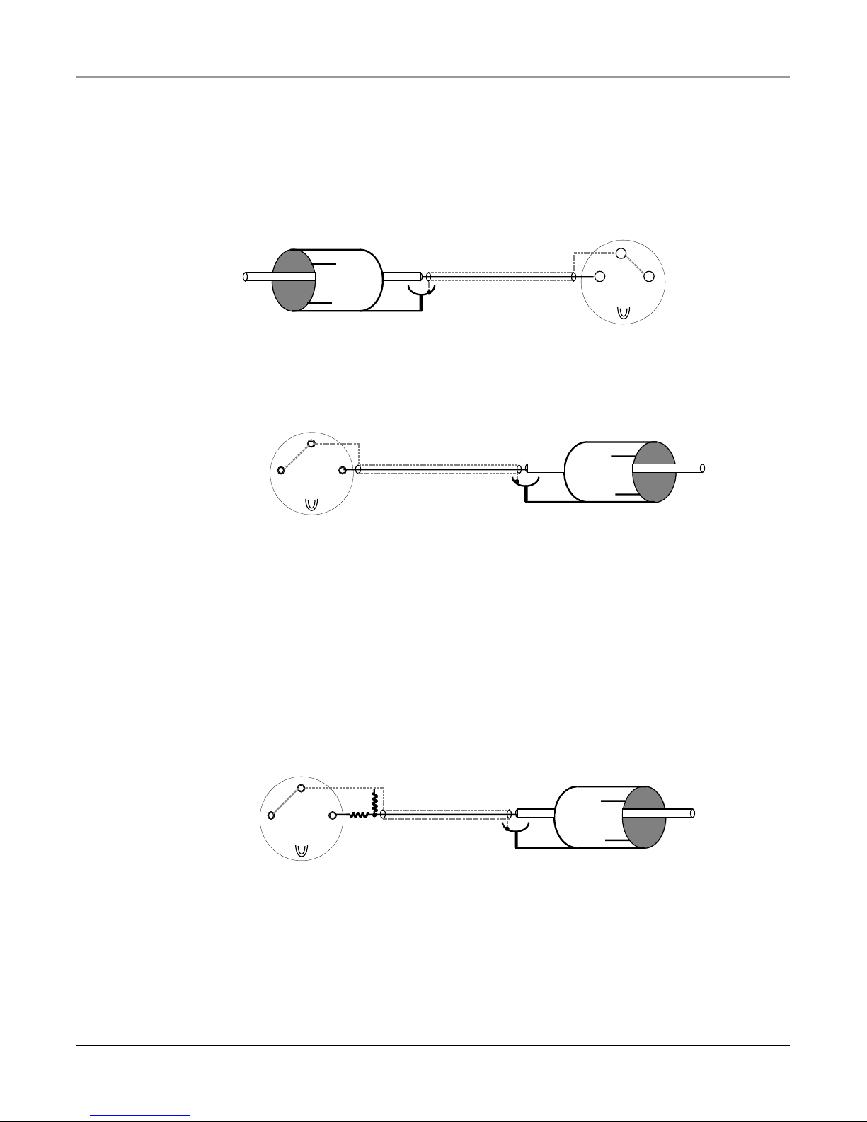
You can easily make an adaptor to bring S/PDIF signals into the
DMTi
’s AES/
EBU inputs. The shield of the RCA connector is wired to pins 1 and 3 of the
XLR connector, and the center (hot) conductor of the RCA connector is wired
to pin 2 of the XLR. Here’s a diagram of such an adaptor:
3
2
1
From S/PDIF Out
A similar adapter can be used to send AES/EBU signals from the
To AES In (solder side)
DMTi
to an
S/PDIF device:
3
1
From AES Out
(solder side)
2
To S/PDIF In
The signal at the AES/EBU outputs, however, is at the higher level required by
AES/EBU devices, and it is possible, although unlikely, that the input on an
S/PDIF device could be damaged if it is connected directly to one of these
outputs. An attenuating adapter can avoid this problem. If you are in doubt,
check with the manufacturer of the S/PDIF equipment to see if it can handle
the elevated signal level. To make an attenuating adapter, insert an 82.5Ω
resistor between pin 2 of the XLR connector and the center conductor of the
coaxial cable, and connect a 750Ω resistor from pin 3 of the XLR connector to
the center conductor of the coaxial cable:
1
From AES Out (solder side)
Generally speaking, when sending a digital audio signal to an S/PDIF device,
the Output Format switch for that signal should be set to “Cnsmr”. Also note
that S/PDIF signals sometimes have trouble travelling long distances. Using
high-quality video-compatible coaxial cable and making cable runs as short as
possible will keep problems to a minimum.
10
3
750Ω
82.5Ω
2
To S/PDIF In
DMTi
Page 11

Using the
DMTi
: Scenarios
The next 22 pages will deal with specific scenarios for using the
tried to cover as many applications as possible, but you may find others.
Chances are, however, that you will find information relevant to your
application in one or more of the scenarios presented here. Please read the first
two scenarios even if their situation doesn’t apply to you: you will find them
useful in understanding how the
DMTi
works.
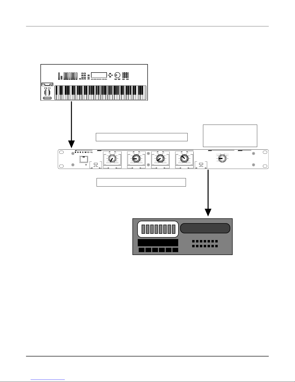
K2500 to Modular Digital Multitrack (DA-88/ADAT)
Application
This is one of the most useful applications of the
two to eight channels simultaneously from a Kurzweil K2500-series
instrument directly to a modular digital multitrack recorder (“MDM”) such as
an Alesis ADAT or TASCAM DA-88, without leaving the digital domain. The
DMTi
provides the proper signal conversions and also provides proper sync for
recording on the digital multitrack.
DMTi
DMTi
. We have
. You can record from
What you need
• The K2500 must be equipped with a KDS digital input/output or KDFX
digital effects option.
• The
DMTi
must have an ADAT or DA-88 (TDIF-1) option, depending on
which type of modular digital multitrack you are using.
Hookup
• Using the 3-meter KDS cable supplied with the
meter KDS cable), connect the KDS Output on the K2500 to the KDS input
on the
• Connect the modular digital multitrack to the
vided with the recorder for connecting two decks together. DA-88-format
decks use a single 25-pin “D” connector, while ADAT-format decks use one
optical and one sync cable for input and a similar pair for output.
• If you want to use an external source of word clock as the sync master,
connect that source to the
• You must use the multitrack recorder as the sync master if you are
overdubbing tracks (see next page).
DMTi
.
DMTi
’s Word Clock Input — however…
DMTi
(or the optional 15-
DMTi
using the cable(s) pro-
11User’s Guide
Page 12

Settings
• Determine which MDM tracks you want to record to, and choose a source
pair from the K2500 for each pair of MDM tracks. Set the Destination knob
that is assigned to each output pair (going to the MDM) so that its input is
the desired pair coming from the KDS. For example, if you want to record
KDS pair A onto MDM tracks 1 and 2, set Destination 1 (which selects the
source for MDM tracks 1 and 2) to KDS A. If you want to record KDS pair B
onto MDM tracks 5 and 6, set Destination 3 (which selects the source for
MDM tracks 5 and 6) to KDS B. Set the other Destination knobs
accordingly.
• For your initial tracks, it is usually easiest to use the MDM as the sync
master: set Clock Select to MDM. You may, however, set it to KDS
(provided you are recording at 48 kHz—remember, the KDS bus always
runs at 48 kHz), or one of the Int settings. Alternatively, if you are using an
external clock master, you can set Clock Select to WDCLK. Note that any
time you are not using the MDM as the clock master, you must make sure
the multitrack tape deck is set to sync to an external clock signal.
When overdubbing to the MDM…
Modular Digital Multitrack decks cannot use different clock sources for
recording and playback at the same time. Therefore, if you are recording tracks
to a multitrack digital tape that already has one or more tracks recorded on it,
then the MDM must be the sync master: set Clock Select to MDM. There is an
exception to this rule: if you are using an external clock source, then both the
DMTi
and the MDM must be set up to slave to that source.
Special note for ADAT users:
If you are using multiple ADAT units, then one ADAT must act as sync master
for all of the others, as well as for any
decks. The sync signal is carried through the system on the Alesis Sync cable.
The
DMTi
can access that signal, provided a jumper on the ADAT option’s
circuit board is set correctly. See Appendix A for details.
DMTi
that is feeding signals to any of the
12
DMTi
Page 13
KDS Out
KDS In
Knob
positions
choose
sources
Source: KDS A KDS C KDS B KDS D
Source
outing
R
AES 1
AES 2
D
1-2
C
3-4
B
A
KDS MDM
AES 1, MDM 1-2, KDS A, KDS Rtn
5-6
7-8
Output Format
ower
P
Pro Cnsmr Pro Cnsmr
Destination 1 Destination 1 Destination 2
Source
AES 1
D
C
B
A
KDS
AES 2, MDM 3-4, KDS B
AES 2
1-2
3-4
5-6
7-8 A
MDM
Source
AES 1
AES 2
D
1-2
3-4
C
5-6
B
7-8
KDS
MDM KDS
Destination 3 Destination 4 Destination 2-4
Destination: MDM 1-2 MDM 3-4 MDM 5-6 MDM 7-8
Knob
labels
show
destinations
to digital multitrack
DA-88: TDIF-1 I/O
ADAT: Digital In & Sync In
01:23:45:29
Source
AES 1
D
C
B
A 7-8
MDM
AES 4, MDM 7-8, KDS DAES 3, MDM 5-6, KDS C
Clock Select
must
be set to MDM
when overdubbing
utput Sync Clock Select
Output Format
O
AES 1
AES 2
MDM
KDS
AES 2
1-2
3-4
5-6
WDCLK
Int 44.1K
Int 48K
DMT
MDT
igital
ulti-
interface
rack interface
Output from DA-88 or
ADAT interface option
Variation: Sending to a DA-88- or ADAT-compatible mixer
The
DMTi
can be used to bring a K2500 signal directly into a digital mixer with
a DA-88- or ADAT-compatible input. The procedure is the same as when
working with a digital multitrack recorder. The mixer must be set up to sync to
external sample-rate clock.
13User’s Guide
Page 14

Modular Digital Multitrack to K2500
Application
This is the reverse of the preceding scenario: you have a track on a modular
digital multitrack tape which you want to load (sample) into the K2500 for
manipulation and/or MIDI-triggered playback.
What you need
• The K2500 must be equipped with the Sampling option and either the KDS
digital input/output option or the KDFX digital effects option.
• The
Hookup
DMTi
must have an ADAT or DA-88 (TDIF-1) option, depending on
which type of modular digital multitrack you are using.
• Using the 3-meter KDS cable supplied with the
meter KDS cable), connect the KDS Output on the K2500 to the KDS input
on the
Return path—that’s what we’ll be using.)
• Connect the modular digital multitrack to the
vided with the recorder for connecting two decks together. DA-88-format
decks use a single 25-pin “D” connector, while ADAT-format decks use one
optical and one sync cable for input and a similar pair for output.
• If you want to use an external source of word clock as the sync master,
connect that source to the
DMTi
. (If this sounds backwards, remember the KDS interface has a
DMTi
’s Word Clock Input.
DMTi
(or the optional 15-
DMTi
using the cable(s) pro-
Settings
• Determine which pair of MDM tracks you want to sample. Select that pair
with the Destination 1 knob, by setting it to one of the MDM positions. The
Destination 1 knob routes the signal to the KDS Rtn bus.
• In most cases, Clock Select should be set to KDS. It can also be set to Int
48K or MDM, if the source tape was recorded at 48 kHz (the KDS bus runs
at 48 kHz). Alternatively, if you are using an external 48 kHz clock master,
you can set Clock Select to WDCLK.
• Set the following parameters on the K2500’s Sample Page: Input to “Digital”
and Src to “Rtn”.
Note: if you want to sample from the MDM at a rate other than 48 kHz, you
can go from one of the
See Page 22.
14
DMTi
’s AES/EBU outputs into the K2500’s digital input.
DMTi
Page 15

from digital multitrack
DA-88: TDIF-1 I/O
ADAT: Digital In & Sync In
to DMTi’s DA-88 or
ADAT interface option
01:23:45:29
Knob
position
Source: MDM 1-2
Source
outing
R
AES 1
AES 2
D
C
B
Output Format
A
ower
P
Pro Cnsmr Pro Cnsmr
KDS MDM
AES 1, MDM 1-2, KDS A, KDS Rtn
Destination 1 Destination 1 Destination 2
Destination: KDS Rtn
Knob
label
shows
chooses
Source
AES 1
1-2
D
3-4
C
B
5-6
7-8
A
KDS
AES 2, MDM 3-4, KDS B
destination
source
AES 2
1-2
3-4
5-6
7-8 A
MDM
Source
AES 1
AES 2
D
1-2
3-4
C
5-6
B
7-8
KDS
MDM KDS
Destination 3 Destination 4 Destination 2-4
Source
AES 1
D
C
B
A 7-8
MDM
AES 4, MDM 7-8, KDS DAES 3, MDM 5-6, KDS C
AES 2
1-2
3-4
5-6
Output Format
utput Sync Clock Select
O
AES 1
AES 2
MDM
KDS
interface
DMT
WDCLK
Int 44.1K
igital
Int 48K
rack interface
MDT
ulti-
KDS In
(
Return
KDS Out
(
Return
)
)
15User’s Guide
Page 16

K2500 to AES/EBU
Applications
Sending the output of a K2500-series instrument’s 8-channel KDS bus to one or
more AES/EBU devices. Examples:
• Mastering to a DAT from the K2500
• Recording two or more channels from the K2500 to a hard-disk audio system
• Tracking from the K2500 to a multitrack tape deck with AES/EBU inputs
• Mixing the outputs of the K2500 on a digital mixer
• Sending an output of the K2500 to an external signal processor
What you need
• The K2500 must be equipped with a KDS digital input/output or KDFX
digital effects option.
• Use a KDS cable (included with the
• AES/EBU cable(s).
Hookup
DMTi
) to connect the K2500 to the
DMTi
.
• Connect the KDS cable between the K2500 and the
• Connect AES/EBU cables from the
use.
DMTi
’s outputs to the inputs you want to
DMTi
’s KDS In connector.
Settings
• Set the Destination knobs for all of the pairs that you are using to one of the
KDS pairs.
• Set the Clock Select to KDS, unless you want to record at a different sample
rate than the KDS’s 48 kHz rate, in which case you can use the Int 44.1K Hz
clock.
• Variation 1: using the AES/EBU receiver as the clock
master
In some situations, such as when using an AES/EBU device that won’t lock to
incoming digital signals, you will want to use that device as the synchronization master.
Connect an AES/EBU cable from the output of the AES/EBU device to one of
the
DMTi
’s AES inputs. Set the Clock Select to that AES input. Make sure
the AES/EBU device’s clock is set to “internal”. Now the sample-rate clock
generated by the AES/EBU device (which typically is present at all times)
16
DMTi
Page 17

K2500
KDS
Source
outing
R
AES 1
D
C
B
Output Format
A
ower
P
KDS MDM
Pro Cnsmr Pro Cnsmr
AES 1, MDM 1-2, KDS A, KDS Rtn
Destination 1 Destination 1 Destination 2
Source
AES 2
AES 1
1-2
D
3-4
C
5-6
B
7-8
A
KDS
MDM
AES 2, MDM 3-4, KDS B
Source
AES 2
AES 1
1-2
3-4
5-6
7-8 A
AES 2
D
1-2
3-4
C
5-6
B
7-8
KDS
MDM KDS
Destination 3 Destination 4 Destination 2-4
AES 1
D
C
B
A 7-8
AES 4, MDM 7-8, KDS DAES 3, MDM 5-6, KDS C
AES/EBU
(or S/PDIF)
AES/EBU device
will be the master. Be careful that you don’t route the audio signal from the
AES/EBU device back to its own input, or you will create a feedback loop.
• Variation 2: K2500 to S/PDIF
Common S/PDIF devices include DAT decks, computer sound cards, and
signal processors. They may have optical or coaxial (RCA) connectors.
Source
AES 2
1-2
3-4
5-6
MDM
Output Format
utput Sync Clock Select
O
AES 1
AES 2
MDM
KDS
interface
DMT
WDCLK
Int 44.1K
igital
Int 48K
rack interface
MDT
ulti-
(Clock)
Decide which AES/EBU output(s) you want to use, and set the appropriate
output format switch(es) to “Cnsmr”. For devices with optical inputs,
connect an optical cable between the
axial inputs, use AES/EBU-to-S/PDIF adapters at the
Page 10).
Set the S/PDIF device’s clock to “external”. If there’s no way to do this—the
S/PDIF device cannot be locked to an incoming digital signal—then you
must use its clock as the master by routing its output back to the
detailed above, and setting the
DMTi
and the S/PDIF input. For co-
DMTI
’s outputs (see
DMTi
’s Clock Select switch accordingly.
DMTi
, as
17User’s Guide
Page 18

AES/EBU to K2500
Application
Sending a channel pair from an AES/EBU device to a K2500-series
instrument’s KDS bus input. Examples:
• Sampling from a DAT deck, CD player, or digital mixer
• Transferring a stereo pair from a multitrack deck or disk system to the K2500
• Returning a signal to the K2500 from a signal processor
(Note: Since a Sampling-option-equipped K2500 has AES/EBU and S/PDIF
optical inputs, you can sample directly from a digital source without the
However, using the
the digital signal. Also, if you already have the K2500 and
gether for another purpose, this will save the hassles of rewiring.
What you need
• The K2500 must be equipped with the Sampling option and the KDS digital
input/output option or KDFX digital effects option.
• Use a KDS cable (included with the
• AES/EBU cable(s).
DMTi
gives you the option of changing the sample rate of
DMTi
hooked to-
DMTi
) to connect the K2500 to the
DMTi
DMTi
.
.
Hookup
• Connect the KDS cable between the K2500 and the
(not the KDS Out).
• Connect AES/EBU cables from the output on the AES/EBU device to one of
the
DMTi
’s two AES inputs.
DMTi
’s KDS In connector
Settings
• Destination 1 controls the input to the K2500 (using the “return” pair on the
KDS In bus). Set it to AES1 or AES2, depending on which input you are
using.
• Set the Clock Select to KDS to make sure the outgoing signal is compatible
with the KDS bus. Alternatively, you can use the Int 48K setting, or you can
use one of the AES settings, provided the signal at the corresponding AES
input is at 48 kHz.
• Set the following parameters on the K2500’s Sample Page: Input to “Digital”
and Src to “Rtn”.
18
DMTi
Page 19

AES/EBU device
AES/EBU
(or
S/PDIF)
Source
outing
R
AES 1
AES 2
D
1-2
C
3-4
B
A
KDS MDM
AES 1, MDM 1-2, KDS A, KDS Rtn
5-6
7-8
Output Format
ower
P
Pro Cnsmr Pro Cnsmr
Destination 1 Destination 1 Destination 2
K2500
• Variation: S/PDIF to K2500
Source
AES 2
AES 1
1-2
D
C
3-4
5-6
B
A
7-8 A
KDS
MDM
AES 2, MDM 3-4, KDS B
KDS In
(“return”)
Source
AES 1
D
C
B
KDS
MDM KDS
Destination 3 Destination 4 Destination 2-4
Source
AES 1
D
C
B
A 7-8
MDM
AES 4, MDM 7-8, KDS DAES 3, MDM 5-6, KDS C
AES 2
1-2
3-4
5-6
AES 2
1-2
3-4
5-6
7-8
Output Format
utput Sync Clock Select
O
AES 1
AES 2
MDM
KDS
interface
DMT
WDCLK
Int 44.1K
igital
Int 48K
rack interface
MDT
ulti-
Common S/PDIF sources include DAT decks, computer sound cards, signal
processors, and CD players with digital outputs.
For optical sources, connect an optical cable between the S/PDIF device and
the
DMTi
’s optical input. Set the selector switch for the AES1 input to “Opti-
cal”. Coaxial sources can be connected to either of the
using an S/PDIF-to-AES/EBU adapter at the input (see Page 10).
DMTi
’s AES inputs,
19User’s Guide
Page 20

K2500 to Pro Tools or other hard-disk system
Application
Recording two or more channels from a K2500-series instrument to a hard-disk
audio system, such as Digidesign’s Pro Tools.
What you need
• The K2500 must be equipped with a KDS digital input/output or KDFX
digital effects option.
• Use a KDS cable (included with the
• AES/EBU XLR-to-XLR cable(s), or AES/EBU-to-S/PDIF adapters, depending on which types of inputs the Pro Tools system has.
Hookup
DMTi
) to connect the K2500 to the
DMTi
.
• Connect the KDS cable between the K2500 and the
• Connect AES/EBU (or S/PDIF) cables from the
Tools inputs that you want to use.
• You may want to record using Pro Tools’ sample-rate clock as the master, in
which case you have two options:
1) connect a BNC-to-BNC coaxial cable from Pro Tools’ word clock output
to the
outputs to one of the AES inputs on the
DMTi
’s Word Clock In, or
2) connect an AES/EBU (or S/PDIF) cable from one of Pro Tools’ digital
DMTi
.
DMTi
.
DMTi
’s outputs to the Pro
Settings
• Set the Destination knobs for all of the pairs that you are using to one of the
KDS pairs.
• If you are not using Pro Tools as the clock master, set Clock Select to KDS,
or one of the Int settings. Also, you must set the “Sync” switch in the Pro
Tools setup software to “Digital”.
• If you are using Pro Tools as the clock master, set Clock Select accordingly:
either to WDCLK, if you are using that option, or to AES1 or AES2 if you
are using that option. Set the “Sync” switch in the Pro Tools setup software
to “Internal”.
20
DMTi
Page 21

K2500
KDS
Source
outing
R
AES 1
D
C
B
Output Format
A
ower
P
KDS MDMAKDS
Pro Cnsmr Pro Cnsmr
AES 1, MDM 1-2, KDS A, KDS Rtn
Destination 1 Destination 1 Destination 2
Source
AES 1
AES 2
1-2
D
3-4
C
B
5-6
7-8
AES 2, MDM 3-4, KDS B
Source
AES 1
AES 2
1-2
D
3-4
C
5-6
B
7-8 A
MDM
KDS
MDM KDS
Destination 3 Destination 4 Destination 2-4
AES 2
1-2
3-4
5-6
7-8
AES/EBU
Hard-disk audio
system
Source
AES 1
D
C
B
A 7-8
AES 4, MDM 7-8, KDS DAES 3, MDM 5-6, KDS C
utput Sync Clock Select
O
AES 2
1-2
3-4
5-6
MDM
Output Format
AES 1
AES 2
MDM
KDS
interface
DMT
WDCLK
Int 44.1K
igital
Int 48K
rack interface
MDT
ulti-
(Clock:
from AES/EBU output
or Word Clock)
Returning signals from Pro Tools to the K2500
You can also route signals from Pro Tools back into the K2500 for sampling or
processing purposes. Use the setup for AES/EBU or S/PDIF to K2500 on
Pages 18 and 19. For best results, set Clock Select to KDS when recording to
the K2500.
21User’s Guide
Page 22

Modular Digital Multitrack to AES/EBU
(including Pro Tools)
Application
Moving tracks back and forth between a modular digital multitrack tape
recorder and one or more AES/EBU devices. Examples:
• Dumping tracks from MDM to DAT, and perhaps changing the sample rate
in the process.
• Bouncing tracks through a digital signal processor and re-recording them in
real time.
• Transferring tracks from digital multitrack tape to a hard-disk audio system
for on-disk processing, and then transferring them back to tape.
• Sampling tracks from a modular digital multitrack into a K2500 at a rate
other than the KDS bus’s 48 kHz.
What you need
• The
• AES/EBU (XLR, AES/EBU-to-S/PDIF, or optical) cable(s).
DMTi
must have an ADAT or DA-88 (TDIF-1) option.
Hookup
• Connect the modular digital multitrack recorder to the
cable(s) provided with the recorder for connecting two decks together: one
25-pin “D” cable for a DA-88; one optical and one sync cable for an ADAT’s
input and a similar pair for output.
• Connect AES/EBU cables from the
inputs you want to use.
• If you want to route signals back to the modular digital multitrack for
bouncing or re-recording, connect cables from the AES/EBU device’s
output(s) to the AES1 and/or AES2 inputs on the
only connect two pairs of channels at a time this way.
• If you want to use an external source of word clock as the sync master,
connect that source to the
source to the modular digital multitrack’s word clock input.
• You must use the modular digital multitrack as the sync master if you are
overdubbing tracks onto it (see below).
DMTi
DMTi
’s AES outputs to the AES/EBU
’s Word Clock Input. Also connect the clock
DMTi
using the
DMTi
. Note that you can
Settings
• Set the Destination knobs to MDM, AES1, or AES2, depending on how you
want the signals to be routed.
22
DMTi
Page 23

00:00:00:00
SMPTE
or MIDI
Time
Code
• If you are recording to the modular digital multitrack, and there are any
tracks already recorded on the tape, you must set Clock Select to MDM,
with one exception: if you are slaving the recorder to external word clock,
then set the
DMTi
‘s Clock Select to WDCLK and set the tape deck to slave
to external word sync as well. Also make sure the other AES/EBU device(s)
is set up to lock to external sync.
• If you are not overdubbing onto the digital multitrack, you have more
choices. Set the Clock Select to MDM, WDCLK (if external word clock is
present), one of the AES inputs if they are in use, or one of the Int settings.
• Alternatively, if you are using an AES/EBU device that does not lock to
external sync, you can have the
DMTi
lock to it, by making sure there is a
cable from the output of the AES/EBU device to one of the AES inputs, and
setting the Clock Select to that AES input.
MDM
Source
outing
R
AES 1
D
C
B
Output Format
A
ower
P
KDS MDMAKDS
Pro Cnsmr Pro Cnsmr
AES 1, MDM 1-2, KDS A, KDS Rtn
Destination 1 Destination 1 Destination 2
Source
AES 2
AES 1
1-2
D
3-4
C
5-6
B
7-8
AES 2, MDM 3-4, KDS B
AES/EBU
out and in
Source
AES 2
AES 1
1-2
D
3-4
C
5-6
B
7-8 A
MDM
KDS
Destination 3 Destination 4 Destination 2-4
AES 2
1-2
3-4
5-6
7-8
MDM KDS
Source
AES 1
D
C
B
A 7-8
AES 4, MDM 7-8, KDS DAES 3, MDM 5-6, KDS C
utput Sync Clock Select
O
AES 2
1-2
3-4
5-6
MDM
Output Format
AES 1
AES 2
MDM
KDS
interface
DMT
WDCLK
Int 44.1K
igital
Int 48K
rack interface
MDT
ulti-
(Clock:
from external
Digital signal processor,
DAT deck, etc.
video or word
clock, if used)
Hard-disk audio
system
Special note for ADAT users:
If you are using multiple ADAT units, then one ADAT must act as sync master
for all of the others, as well as for any
decks. The sync signal is carried through the system on the Alesis Sync cable.
The
DMTi
can access that signal, provided a jumper on the ADAT option’s
circuit board is set correctly. See Appendix A for details.
DMTi
that is feeding signals to any of the
23User’s Guide
Page 24

Timecode issues
SMPTE timecode is not carried along with the audio and clock data in any of
the standard digital formats, and therefore the
timecode between devices. If you need to synchronize two devices’ SMPTE
times, for example to transfer tracks from a modular digital multitrack to a
hard-disk audio system while keeping everything locked to video, you will
need to set up a specific connection between them for that purpose. Decide
which device is the timecode master and which is the slave (there can be more
than one slave), and then use standard audio cables to connect the “timecode
out” jack of the master device to the “timecode in” jack(s) of the slave(s); or if
the devices use MIDI Time Code, use a MIDI cable from the master to the
slave(s).
Note that in a larger studio such as a video post-production suite, the master
timecode device does not necessarily have to be either the MDM or the AES/
EBU device; a videotape or SMPTE generator can act as the master, with both
audio devices slaved to it.
Keep in mind that the timecode master/slave relationship is independent of the
sample-rate or word clock master/slave relationship: a device can be the SMPTE
master at the same time it is following an external sample-rate clock, or vice
versa.
DMTi
does not pass SMPTE
24
DMTi
Page 25

AES to AES with resampling
Application
Converting an AES/EBU signal into a different AES or S/PDIF format and/or
at a different sampling rate. Examples:
• Making a dub of a 48-kHz DAT onto another DAT at 44.1 kHz.
• Recording a CD (from a player with an S/PDIF output) onto a DAT or digital videotape at 48 kHz.
• Copying an old PCM-F1 digital recording (which used a 44.056-kHz
sampling rate) to DAT at 44.1-kHz, without changing the speed. Normally
there would be a speed shift of 0.1% (3.6 seconds per hour) when the DAT is
played back.
• Correcting the speed and/or sample rate of other digital recordings using
pull-down (video-based) sample rates.
What you need
• AES/EBU (XLR, AES/EBU-to-S/PDIF, or optical) cable(s).
• Word clock cables if you are planning to lock to an external sync source.
Hookup
• Connect the source to either AES input; connect the recording deck to any
AES output.
• If locking the output to an external source of sample-rate clock, connect that
signal to the Word Clock input.
Settings
• Set the Destination knobs to route the signal appropriately.
• If the sample rate of the dub is to match that of the original, set Clock Select
to AES1 or AES2 depending on where the source is connected.
• If the sample rate is to be changed, set Clock Select to one of the Int clock
rates.
• If the sample rate is being determined by an external sync source, set Clock
Select to WDCLK.
• Set the recording device to lock to external digital sync. Alternatively, if the
recording device cannot lock to external sync, you can have the
it, by making sure there is a cable from the output of the recording device to
the
DMTi
’s unused AES input, and setting Clock Select to that AES input.
DMTi
lock to
Note: the
in the digital audio signal, so if that flag is set in your source recording, it will
not be set in the copy.
DMTi
does not pass the Serial Copy Management System (SCMS) flag
25User’s Guide
Page 26

Multimedia sources (samplers, CD, sound cards)
to Modular Digital Multitrack
Application
Modular digital multitracks allow recording on 8 tracks simultaneously, but if
those tracks are coming from different digital sources, they will not record
properly. A modular digital multitrack can only sync to one incoming digital
source at a time, and so any other incoming signals will be out of sync, with
resultant signal degradation.
The
DMTi
synchronizes the signals before they get to the modular digital multitrack. Up to four channels of AES/EBU or S/PDIF audio from digital samplers, signal processors, computer audio cards, DAT decks, and/or CD players
can be combined this way, along with two or more channels from a Kurzweil
K2500-series instrument.
Note that this same setup can also be used with a digital mixer that has a
DA-88- or ADAT-compatible interface, as described on Page 13. The mixer
should be set up to lock to external sample-rate clock.
What you need
• The
• AES/EBU (XLR, AES/EBU-to-S/PDIF, or optical) cables.
• Word clock cables if you are planning to lock to an external sync source.
• If you are using a K2500-series instrument as one of the sources, it must be
DMTi
must have an ADAT or DA-88 (TDIF-1) option.
equipped with a KDS digital input/output or KDFX digital effects option.
Hookup
• Connect the AES/EBU or S/PDIF sour ces to the AES1 and AES2 inputs.
• Connect the K2500 (if you are using one) to the
using the KDS cable included with the
• Connect the modular digital multitrack to the
vided with the recorder for connecting two decks together. The DA-88 uses
a single 25-pin “D” connector, while the ADAT uses one optical and one
sync cable for input, and a similar pair for the output.
• If you want to use an external source of word clock as the sync master,
connect that source to the
• You must use the multitrack recorder as the sync master if you are
overdubbing tracks (see next page).
DMTi
’s Word Clock Input — however…
DMTi
.
DMTi
DMTi
’s KDS In connector
using the cable(s) pro-
26
DMTi
Page 27

Settings
• Set the Destination knobs for all of the pairs that you are using to either one
of the AES inputs or one of the KDS pairs, as appropriate.
• For your initial tracks, it is often easiest to use the MDM as the sync master:
set Clock Select to MDM. If you want to use one of the other sources as the
sync master, you can, or you can use one of the Int settings or WDCLK. If
you are using anything other than the MDM as the master, however, you
must make sure the modular digital multitrack deck is set to sync to an
external clock signal. (Multiple ADAT users see the “Special Note” on Page 23.)
When overdubbing to the MDM…
Modular Digital Multitrack decks cannot use different clock sources for
recording and playback at the same time. Therefore, if you are recording tracks
to a multitrack digital tape that already has one or more tracks recorded on it,
then the MDM must be the sync master: set Clock Select to MDM. There is an
exception to this rule: if you are using an external clock source, then both the
DMTi
and the MDM must be set up to slave to that source.
CD
player
Computer
with sound
card
AES 1
D
C
B
AES 2, MDM 3-4, KDS B
AES2
In
Source
Source
AES 2
AES 1
1-2
D
3-4
C
5-6
B
7-8 A
MDM
KDS
MDM KDS
Destination 3 Destination 4 Destination 2-4
AES 2
AES 1
1-2
D
3-4
C
5-6
B
7-8
A 7-8
AES1
In
Source
outing
R
AES 1
AES 2
D
1-2
C
3-4
B
Output Format
ower
P
Pro Cnsmr Pro Cnsmr
Destination 1 Destination 1 Destination 2
5-6
A
7-8
KDS MDMAKDS
AES 1, MDM 1-2, KDS A, KDS Rtn
MDM
01:23:45:2
(Clock:
KDS
In
from external
video or word
clock, if used)
Source
AES 4, MDM 7-8, KDS DAES 3, MDM 5-6, KDS C
utput Sync Clock Select
O
AES 2
1-2
3-4
5-6
MDM
Output Format
AES 1
AES 2
MDM
KDS
interface
DMT
WDCLK
Int 44.1K
igital
Int 48K
rack interface
MDT
ulti-
27User’s Guide
Page 28

Multimedia sources to digital mixer
Application
With the advent of true digital mixers, it becomes crucial for there to be a way
to synchronize digital streams, so that multiple digital signal sources can be
used with these mixers. A digital mixer with AES/EBU inputs can only sync to
one incoming digital source—generally, it is the signal appearing at the first
input. If signals at the other inputs are not synchronized to the first signal,
audible errors will occur.
The
DMTi
synchronizes the signals before they get to the mixer. Up to four
channels of AES/EBU or S/PDIF audio from digital samplers, signal
processors, computer audio cards, DAT decks, and/or CD players can be
combined this way, along with two or more channels from a Kurzweil K2500series instrument.
Note: if the mixer has DA-88- or ADAT-compatible inputs, you can treat it
exactly as if it were a multitrack digital recorder (see Page 13).
What you need
• AES/EBU (XLR, AES/EBU-to-S/PDIF, or optical) cables.
• If you are using a K2500-series instrument as one of the sources, it must be
equipped with a KDS digital input/output or KDFX digital effects option.
• Word clock cables if you are planning to lock to an external sync source.
• If the mixer uses ADAT- or DA-88-format digital inputs, then the
have the appropriate option.
DMTi
must
Hookup
• Connect the AES/EBU or S/PDIF sour ces to the AES1 and AES2 inputs.
• Connect the K2500 (if you are using one) to the
using the KDS cable included with the
• Connect the digital mixer using either AES/EBU cables, S/PDIF cables and
adapters, or MDM cable(s), depending on the mixer’s input format. (Some
mixers with ADAT inputs do not have a Sync input, and only require the
optical cable to be connected.)
• If you want to use an external source of word clock as the sync master,
connect that source to the
• If the mixer also accepts external sample-rate sync, and you want to use it,
then connect it to the mixer’s word clock input.
DMTi
’s Word Clock Input.
DMTi
.
DMTi
’s KDS In connector
28
DMTi
Page 29

Settings
• Set the Destination knobs for all of the pairs that you are using to either one
of the AES inputs or one of the KDS pairs, as appropriate.
• Set Clock Select to one of the Int settings or WDCLK, as appropriate.
• Variation: Multimedia sources to Pro Tools
Setting up multiple sources for simultaneous recording into Pro Tools is similar to setting them up for digital mixing: the Pro Tools system must have one
and only one sync reference, which can come from the
from one of the sources, or from an external word clock signal which is connected both to the
DMTi
and the Pro Tools interface.
Normally, Pro Tools must be set up to accept external digital sync from the
DMTi
—this is done in software—or else it will try to convert incoming signals
“on the fly”, and this can create errors. If for some reason Pro Tools must be the
master clock, the solution is simple: run a BNC-to-BNC cable from Pro Tools’
word clock output to the
DMTi
’s Word Clock Input, and set Clock Select to
WDCLK.
DMTi
’s internal clock,
Pro Tools
hard-disk
audio
system
CD
player
Computer
with sound
card
AES 1
D
C
B
AES 2, MDM 3-4, KDS B
Source
AES2
In
Source
AES 2
AES 1
1-2
D
3-4
C
5-6
B
7-8 A
MDM
KDS
Destination 3 Destination 4 Destination 2-4
AES 2
1-2
3-4
5-6
7-8
MDM KDS
AES 1
D
C
B
A 7-8
AES 4, MDM 7-8, KDS DAES 3, MDM 5-6, KDS C
AES1
In
Source
outing
R
AES 1
AES 2
D
1-2
C
3-4
B
Output Format
ower
P
Pro Cnsmr Pro Cnsmr
Destination 1 Destination 1 Destination 2
5-6
A
7-8
KDS MDMAKDS
AES 1, MDM 1-2, KDS A, KDS Rtn
AES
Outs
(Clock:
KDS
In
from external
video or word
clock, if used)
Source
utput Sync Clock Select
O
AES 2
1-2
3-4
5-6
MDM
Output Format
AES 1
AES 2
MDM
KDS
interface
DMT
WDCLK
Int 44.1K
igital
Int 48K
rack interface
MDT
ulti-
Pro Tools
interface
word
clock
in or out,
if used
29User’s Guide
Page 30

Converting from one Modular Digital Multitrack
to another (DA-88 to ADAT or vice versa)
Application
Transferring tracks in the digital domain from one type of modular digital
multitrack to another in a single pass.
What you need
Since the
at a time, to do this conversion requires two
DA-88 (TDIF-1) option and the other with the ADAT option, linked together
using the Kurzweil Digital Stream.
DMTi
can only interface with one type of modular digital multitrack
DMTi
s, one equipped with the
Hookup
• Connect the ADAT-format modular digital multitrack to the MDM jack of the
ADAT option-equipped
for connecting two decks together: two optical cables and two sync cables.
• Connect the DA-88-format digital multitrack recorder to the DA-88 optionequipped
recorder for connecting two decks together.
• Determine which deck is the source deck (playback) and which is the
destination deck (record). Connect a KDS cable (included with the
from the KDS Out of the
In of the
bi-directionally between decks, use two KDS cables.
DMTi
’s MDM jack, using the 25-conductor cable provided with the
DMTi
associated with the destination deck. If you want to transfer
DMTi
, using the cables provided with the recorder
DMTi
associated with the source deck, to the KDS
DMTi
)
• You may want to use an external source of word clock as the sync master.
You can use external word clock for either or both of the decks, but you
must make sure that the word clock feeds both the deck and its associated
DMTi
. Connect the source of word clock to the
and to the modular digital multitrack’s word clock input.
• If you want to preserve SMPTE timecode numbers on the tape, connect an
appropriate cable from the source deck’s SMPTE or MIDI Time Code output
to the corresponding input on the destination deck. (See Page 32 for more
on timecode.)
30
DMTi
’s Word Clock Input,
DMTi
Page 31

Settings
01:23:45:29
On the source
5-6, and MDM 7-8, respectively. Set Clock Select to MDM, unless you are
using external word clock to control the source deck, in which case set it to
WDCLK. (Multiple ADAT users see the “Special Note” on Page 12.)
On the destination
C, and KDS D, respectively. Set Clock Select to MDM, unless you are using
external word clock to control the destination deck, in which case set it to
WDCLK.
(External SMPTE and/or
machine control)
DMTi
, set Destination 1 through 4 to MDM 1-2, MDM 3-4, MDM
DMTi
, set Destination 1 through 4 to KDS A, KDS B, KDS
ADAT
In
TDIF-1
SMPTE or MIDI Time
Code and/or machine
control
source deck
MDM
ADAT
Out
ower
P
Source
outing
R
AES 1
D
C
B
Output Format
A
KDS MDMAKDS
Pro Cnsmr Pro Cnsmr
AES 1, MDM 1-2, KDS A, KDS Rtn
Destination 1 Destination 1 Destination 2
Source
AES 2
AES 1
1-2
D
3-4
C
5-6
B
7-8
AES 2, MDM 3-4, KDS B
Source
AES 2
AES 1
1-2
D
3-4
C
5-6
B
7-8 A
MDM
KDS
MDM KDS
Destination 3 Destination 4 Destination 2-4
AES 2
1-2
3-4
5-6
7-8
Source
AES 1
D
C
B
A 7-8
AES 4, MDM 7-8, KDS DAES 3, MDM 5-6, KDS C
utput Sync Clock Select
O
AES 2
MDM
AES 1
1-2
AES 2
3-4
MDM
5-6
KDS
Output Format
interface
DMT
WDCLK
Int 44.1K
igital
Int 48K
rack interface
MDT
ulti-
(Clock:
from external
video or word
clock, if used)
KDS Out
In/Out
ower
P
Source
outing
R
AES 1
D
C
B
Output Format
A
KDS MDMAKDS
Pro Cnsmr Pro Cnsmr
AES 1, MDM 1-2, KDS A, KDS Rtn
Destination 1 Destination 1 Destination 2
Source
AES 1
AES 2
1-2
3-4
5-6
7-8
D
C
B
AES 2, MDM 3-4, KDS B
AES 2
MDM
KDS In
Source
AES 1
AES 2
1-2
3-4
5-6
7-8 A
1-2
D
3-4
C
5-6
B
7-8
KDS
MDM KDS
Destination 3 Destination 4 Destination 2-4
Source
AES 1
D
C
B
A 7-8
AES 4, MDM 7-8, KDS DAES 3, MDM 5-6, KDS C
utput Sync Clock Select
O
AES 2
MDM
AES 1
1-2
AES 2
3-4
MDM
5-6
KDS
Output Format
interface
DMT
WDCLK
Int 44.1K
igital
Int 48K
rack interface
MDT
ulti-
MDM
01:23:45:29
destination deck
31User’s Guide
Page 32

Timecode and machine control issues
SMPTE timecode is not carried along with the audio and clock data on the
DA-88 or ADAT buses, and therefore in this setup the
SMPTE timecode between the two tape recorders. If you want to preserve
SMPTE numbers over the tape transfer, you will need to set up a specific
connection between the two decks for that purpose. Use standard audio cables
to connect the “timecode out” jack of the source deck to the “timecode in” jack
of the destination deck. Alternatively, if the devices use MIDI Time Code, use a
MIDI cable from the source to the destination.
You can have the destination deck record the incoming timecode at the same
time that it records the audio, or you can pre-stripe the tape in the destination
deck with SMPTE, making sure the numbers are compatible with the timecode
on the source tape. With either method, you slave the destination deck to the
source deck, or slave both decks to a common source of timecode.
Keep in mind that the timecode master/slave relationship is independent of the
sample-rate clock master/slave relationship: a device can be the SMPTE master
at the same time it is following an external sample-rate clock, or vice versa.
DMTi
will not pass
Various methods are in use to remotely-control the transports of modular
digital multitrack recorders, including Sony 9-pin and MIDI Machine Control.
By taking advantage of these protocols, the destination deck can be controlled
by the source deck, or both decks operated by a common controller. Consult
the manuals of the tape decks for details.
32
DMTi
Page 33

Troubleshooting
The great majority of errors in any digital audio system are caused by problems with digital synchronization, or clocks. The
these problems, but as in any complex system, a thorough understanding of
how these problems occur is necessary for you to get the
correctly.
No sound at all
Besides the obvious problem of missing or defective cables, this may be caused
by a lack of proper clock signal to the
switch is set to an input at which there is an actual signal: for example, if it is
set to WDCLK and there is no signal present at the Word Clock Input, there
may be no audio output. Similarly, there must be signal present at the AES,
MDM, or KDS inputs if any of those are to be the sync master. To determine
whether this is the problem, set Clock Select to one of the Int settings and
make sure that clock is getting to the device connected to the
If there is no sound coming from the AES1 input, make sur e the Input Select
switch is set correctly.
DMTi
is designed to solve
DMTi
DMTi
. Make sure the Clock Select
to perform
DMTi
’s output.
Intermittent audio
This can be caused by clock problems (as above) or by a weak digital signal.
Cables that are too long or are of poor quality can cause the signal to
deteriorate or suffer interference. Keep cables as short as possible, especially if
you are using single-conductor coaxial S/PDIF cable. Coaxial cables designed
for analog audio are not very good for carrying digital signals—instead, use
cables designed for video.
If you are using an AES output to feed an AES/EBU device, make sure its
format switch is set to Pro, to ensure that the correct signal format is being
transmitted. Similarly, if you are feeding an S/PDIF device, make sure the
switch is set to Cnsmr. You may also need to use an attenuating adapter to
bring the signal level down (see Page 10).
Can’t record output
Some recording devices, such as certain DAT decks, may have trouble
receiving or locking to the
audio signal, or not go into record at all.
DMTi
’s output. They may not recognize the digital
33User’s Guide
Page 34

This is caused by the way the
stream. In the AES/EBU digital word is a set of bits known as the “channel
status field” which contains, among other information, a flag denoting the
sample rate of the signal being transmitted. This can be set to “44.1”, “48”, or
“unknown”. When the
in the output signal is set to “44.1”. When Clock Select is set to Int 48K or to
KDS, this flag is set to “48”. With any other settings—AES1, AES2, MDM, or
WDCLK—this flag is set to “unknown”. Some receiving devices may not
accept a digital input with an “unknown” flag, and will not record or lock to it.
Alternatively, some devices, when they receive a signal with an “unknown”
flag, assume that the sample rate is at a particular value (say 48 kHz) and if the
incoming signal is at the wrong value (say 44.1 kHz), it will not record it.
If this situation occurs, use one of the “known” settings for Clock Select:
Int 44.1K or Int 48K. If that is not possible, contact the manufacturer of the
unit in question for assistance.
DMTi
DMTi
handles certain data in the digital audio
’s Clock Select switch is set to Int 44.1K, this flag
Clicks and Pops
These occur when trying to combine two digital streams that are out of sync,
or when trying to convert a digital stream on the fly. The
of-sync streams, but if you are sending data from the
trouble with external synchronization (or doesn’t allow it at all), you can
experience problems of the latter kind. First of all, make sure that the receiving
device is set up to lock to incoming digital data, if possible. Then, check that
the
DMTi
’s output sample rate matches the input sample rate of the device in
question—often you will find that the device has no trouble working with an
external 44.1-kHz clock, but will have a very difficult time if it expects 44.1
kHz and the incoming signal is 48 kHz!
DMTi
deals with out-
DMTi
to a device that has
If you are still having trouble, you may have to lock the
device. Many AES/EBU devices generate a valid signal at their outputs even
when there is no audio playing, and this signal can be used as the
master. For example, the output of a DAT deck that you are recording to can be
looped back to the
using that input for anything else), and the Clock Select switch can be set to
follow it. Be sure not to route the audio signal from the device’s output back to
its own input, or you will get a feedback loop.
34
DMTi
to the receiving
DMTi
through one of the AES inputs (as long as you’re not
DMTi
’s clock
DMTi
Page 35

Another alternative is to use a common source of word clock for both the
and the receiving device, assuming that the receiving device has an input for
it. Make sure that the receiving device is explicitly set up to sync to word
clock—this may be a hardware or software setting, depending on the design.
Make sure that whatever you are using as the master sync device is set to its
own internal clock. If every device in the chain is looking elsewhere for sync,
they will “hunt” each other, with the result that the system will be unstable,
creating noise or even failing completely.
DMTi
Garbage
If the signal deteriorates into a harsh buzz, roar, or “hash” sound, it usually
means that clock sync has been lost. Check to see that the clock source you are
using is generating a valid signal. For example, you may have the
following the digital output of a DAT deck, as described above; when you turn
the deck off, the clock will go off, but the
incoming signals, with unfortunate results.
DMTi
will continue trying to convert
DMTi
’s clock
Pitch changes
These can occur when the wrong sample rate is chosen for a device. Examples:
• A sound file in Pro Tools or a tape on an MDM recorded at 48 kHz is played
back locked to an incoming sample rate of 44.1 kHz. The sound will play
approximately 8.8% slow (about 11/2 semitones flat).
• A recording on a DAT made at “low speed” (32 kHz sampling rate) is played
back using with a deck locked to an external 44.1 kHz signal. The recording
will play back approximately 37.8% fast (about 41/2 semitones sharp).
• A recording made on a video-based digital system using “pulldown” (i.e., a
frame rate of 29.97 fps) and a sample rate of 44.056 kHz, is dubbed to another
system nominally running at 44.1 kHz, using the source as the sync master.
When the dub is played back, it will be 0.1% fast (3.6 seconds per hour).
Most of these problems can be avoided by using the
rate generator (i.e., setting Clock Select to Int 44.1K or Int 48K), and letting
the sources “free run”—that is, use their own internal clocks.
DMTi
’s internal sample-
35User’s Guide
Page 36

Appendix A:
Setting the ADAT Option for Multiple-Machine Synchronization
In a system with multiple ADAT-format tape decks, one and only one of the
decks must act as sync master for all of the others. It must also act as sync
master for any device providing digital audio to any of the decks, and that
includes the
The signal that provides this sync (which is a form of word clock) is carried in
the ADAT’s Sync cable. (The optical cable also carries sync information, but it
is not enough to provide full machine synchronization). Setting the Clock
Select switch on the
selects the sync from the optical cable. Therefore, a special way to get the
to recognize this signal is required.
This is provided by a jumper on the ADAT option board itself. If this jumper is
in one position, then when the Clock Select switch is set to WDCLK, the
syncs to the signal coming into the Word Clock Input on the back panel—in
other words, normal operation. If the jumper is in the other position, and
Clock Select is set to WDCLK, the
coming in from the ADAT Sync cable—which is what you want if you are using
multiple ADA T decks.
DMTi
.
DMTi
to MDM does not access this sync signal—it merely
DMTi
will sync to the master sync signal
DMTi
DMTi
After turning off the power to the
panel securing the ADAT option board, and slide the board out. Locate the
jumper holder, labelled “JP1”, and the rectangular jumper installed on it. To
have the
2 and 3. To return it to normal operation (syncing to Word Clock), set the
jumper so it connects pins 1 and 2.
After you set the jumper, replace the ADAT option board inside the
replace the screws on the back panel. You can change this jumper as often as
you wish. (Just be sure the power is off!)
DMTi
sync to ADAT sync, set the jumper so that it is connecting pins
DMTi
, remove the two screws from the rear
DMTi
and
36
DMTi
Page 37

Appendix B:
The Kurzweil Digital Stream (KDS) Interface
Overview
The KDS interface transmits eight channels of 26-bit or 32-bit audio data per
channel unidirectionally. The 26-bit version is called “KDS26” and the 32-bit
version is called “KDS32”. The sample rate of KDS audio data is 32K–48K per
second ± 12.5% (28K–54K S/s) and is otherwise limited by the sample rates of
the devices producing and receiving the data.
The eight channels are arranged as follows. There are four stereo outputs: A, B,
C, and D. The outputs are produced/received in the order A Left (Chan 0), B
Left (Chan 1), C Left (Chan 2), D Left (Chan 3), A Right (Chan 4), B Right
(Chan 5), C Right (Chan 6), D Right (Chan 7). Each output pair (e.g., A Left
and A Right) may alternately be assigned as separate mono outputs. The KDS
interface is designed to optionally receive 2 channels of up to 24-bit audio data
in differential AES3-1992 Pro format. When this document refers to KDS
signals it excludes optional AES signals. For a description of the AES3-1992
interface see the Journal of the Audio Engineering Society, Volume 40, No. 3, 1992
March, or request a copy of AES3-1992 (ANSI S4.40-1992) from the Audio
Engineering Society.
KDS Block Diagram
KDS
Transmitter
KDS Clock+
KDS Clock-
KDS Sync+
KDS Sync-
KDS Data+
KDS Data-
(opt.)
AES+
AES-
KDS
Receiver
KDS Clock+
KDS Clock-
KDS Sync+
KDS Sync-
KDS Data+
KDS Data-
AES+
(opt.)
AES-
37User’s Guide
Page 38

KDS Interface Timing
The KDS physical layer interface consists of three signals; KDS Clock, KDS
Sync, and KDS Data. The KDS Clock is a clock signal whose frequency equals
208x or 256x the sample rate, for 26 or 32 bits per channel, respectively. The
KDS Sync pulse is valid for one clock cycle each sample frame, such that the
Most Significant Bit (MSB) of the first audio channel is valid in the first clock
cycle following the valid KDS Sync pulse. Audio data is represented as a 2’s
complement number where the MSB is the sign bit. Unused Least Significant
Bits (LSBs) are usually represented as zeros. One can build a KDS input interface that supports both 26- and 32-bit versions by counting the clock transitions between KDS Sync pulses. There are 208 clock transitions for every KDS
Sync pulse for KDS26, and 256 clock transitions for every KDS Sync pulse for
KDS32. The KDS Clock, Sync, and Data are produced as follows:
KDS
CLOCK
KDS
CLOCK
KDS
CLOCK
LSB+1 LSB - Channel 7 MSB - Channel 0 MSB -1
All three signals, Clock, Sync, and Data are typically produced by flip-flops
within the same device to minimize skew. The same can be said for the differ-
ential transmitters and receivers used at each end of the cable. KDS Sync and
KDS Data change at the same time that the KDS Clock transitions from High
to Low. At the receiving end of the cable the rising edge of the KDS Clock is
used to detect KDS Sync and latch KDS Data.
This specification assumes the use of AM26LS31 differential transmitters for
driving the KDS bus and AM26LS32B differential receivers for receiving the
bus. KDS transmission lines are terminated by a single 110-ohm resistor across
the + and - inputs of the receiver.
KDS DC Specifications
KDS interface DC specifications are determined by the differential transmitter
and receiver specified, assuming a 4.75V to 5.25V interface supply voltage. The
output voltage swing is typically 3 Volts. Typical cable attenuation for 15
meters of Belden 9806 results in a swing of approximately 2 Volts at the receiver. Ground potential difference between the KDS transmitter and receiver
should not exceed 1V.
38
DMTi
Page 39

KDS AC Specifications
All timings specified below are measured at 2.5 Volts
Output. Measured at the KDS Output connector, the minimum duration of
KDS Clock Low or High is 32ns. The total time difference from any KDS Clock
output transition to KDS Sync output transition, or from any KDS Clock
output transition to KDS Data output transition, is 12ns maximum. This figure
is the sum of output-to-output skew, plus jitter introduced by the device that
generates the three signals which contributes 2ns (max.), the AM26LS31 which
contributes 6ns (max.), the EMI common mode choke and capacitors which
contribute 1ns (max.), and the combined circuit Low-to-High and High-toLow asymmetry which is 3ns (max.).
Cable. Jitter and skew contributed by the cable consisting of cable reflections,
nonlinearity, and delay mismatch for up to 15 meters of Belden 9806 cable is
estimated to be 3ns, maximum.
Input. A single AM26LS32B is used to receive the three signals. The
AM26LS32B is an improved version of the 26LS32 that features guaranteed
minimum hysteresis and skew, plus a much improved output driver.
Measured at the output of the receiver, the time difference between any KDS
signal transition to any other signal transition should be no more than 22ns,
maximum. This figure is the sum of output to output skew, plus jitter
introduced by the output circuit which is 12ns (max.), the cable which is 3ns
(max.), the receiver which is 4ns (max.), the EMI common mode choke and
capacitors which contribute 1ns (max.), and the asymmetry of the receiving
circuit which is 2ns (max.).
Receiving Logic. The rising edge of KDS Clock is used to detect KDS Sync and
latch KDS Data. With 22ns of total interface skew, jitter, and asymmetry at the
output of the receiver and a 32ns minimum KDS Clock input High and Low
time, the resulting KDS Sync and KDS Data setup and hold time with respect
to the rising edge of KDS Clock is 10ns, minimum. Typical interface skew,
jitter, and asymmetry measured at the output of the DMTi KDS receiver is 3ns,
much lower than the maximum calculated value. If one pays close attention to
minimizing skew in the design, PC board layout, and cable of the KDS interface, the result will be more setup and hold margin at the receiver.
39User’s Guide
Page 40

Here is a simplified schematic showing one KDS output signal pair:
AM26LS31
KDS Xmit
Coilcraft
DLF8000
68pF
5%
NPO
Here is a simplified schematic showing one KDS cable signal pair:
Mini D-15
Female
Mini D-15
Male
Mini D-15
Female
Here is a simplified schematic showing one KDS input signal pair:
Mini D-15
Male
Coilcraft
DLF8000
AM26LS32B
40
68pF
5%
NPO
KDS Rec
110
Ohms
DMTi
Page 41

KDS Interface Cabling and Connectors
The connectors to be used are 15-pin “Mini-D” style as used in IBM-PC VGA
interconnect. The KDS output connector is a receptacle, the KDS input
connector is a plug.
The AMP Part Numbers are as follows:
PC Mount Plug 749767-1
PC Mount Receptacle 748390-6
Cable Mount Plug 748364-1
with 748333-2 (Strip) or 748333-4 (Loose) crimp-on pins
Cable Mount Receptacle 748565-1
with 748610-2 (Strip) or 748610-4 (Loose) crimp-on sockets.
Output drivers are AMD, Philips, Motorola, TI, or National AM26LS31. Input
receivers are AMD or Philips AM26LS32B. Coilcraft DLF8000 common mode
chokes are placed in series with each input or output signal as close as possible
to the KDS output and input connectors. Depending on the system, Tokin
DL03 common mode chokes may be necessary to meet EMI emissions
requirements. The Tokin chokes have separate cores for each twisted pair as
opposed to the Coilcraft part that uses one core for all four pairs. Each output
signal should have a 68pF NPO 5% capacitor tied to chassis ground. These
capacitors should be placed as close to the connector pins as possible with lead
lengths as short as possible. PC board traces for KDS output and input
differential pairs should be kept short and routed parallel to one another.
The KDS connector pinout is as follows:
Pin Name Pin Name Pin Name Pin Name Pin Name
1 Data+ 2 Sync+ 3 Clk+ 4 n/c 5 AES+
11 Data- 12 Sync- 13 Clk- 14 n/c 15 AES6 Gnd 7 Gnd 8 Gnd 9 Gnd 10 Gnd
KDS pins 4 and 14 are not connected. KDS pins 6-10 must be connected to
Chassis Ground via the shortest, lowest impedance path possible. It is
assumed that Logic Ground has a low-impedance connection to Chassis
Ground at some point(s) in the system. The mounting clips for KDS connectors
must also be connected to Chassis Ground via the shortest, lowest-impedance
path possible.
41User’s Guide
Page 42

Note: The standard KDS cable uses only one KDS connector ground pin. KDS
pin 6 is used for the shield drain wire ground on both ends of the cable. The
other ground pins 7-10 are not used with this cable, but must be connected to
ground on both ends. To reduce crosstalk, a cable that uses individually
shielded pairs can be used. Ground pins 6, 7, 8, and 10 are used to connect the
four shields to ground on both ends and pin 9 is connected on both ends with
a larger-gauge wire. This wire is used to reduce ground potential difference
between the transmitter and receiver chassis, reducing common-mode voltage
at the receiver.
The standard KDS interface cables are fabricated with “four-pair” low capacitance cable, Belden 9806 or equivalent, consisting of four unshielded twisted
pairs with a overall braid shield. The connectors are wrapped 360 degrees with
copper foil connected to the cable shield and connector shell at each end. The
cable length must not exceed 15 meters. Kurzweil offers these cables in both 3and 15-meter lengths.
KDS Implementation Chart for Kurzweil Products
Product KDS Output Rate KDS Output AES Input KDS Input Rate KDS Input AES Output
Bits/Channel Bits/Channel
K2500
KDFX 48 KHz x 208 26 Yes N/A N/A N/A
Option
K2500
KDS Out 48 KHz x 208 26 Yes N/A N/A N/A
Option
DMTi 28 KHz x 256 – 32 No 28 KHz x 208 – 26 or 32 Yes
54 KHz x 256 54 KHz x 256
42
DMTi
Page 43

Appendix C: Specifications
Physical
• Width 19 in. (48 cm.) [plus rack ears]
• Depth 10.9 in. (27.7 cm.)
• Height 1.75 in. (4.4 cm.) [1U]
• Weight 10.5 lb. (4.8 kg.)
Electrical
• Voltage Settings 100V 120V 220V 240V
• Safe Voltage Range 85-107 95-125 180-232 190-250
• Frequency Range 48-65 Hz
• Power Consumption 1.0 amp @120V nominal
• Fuse 0.25 amp fast-blow
Environmental
• Temperature (Operating) 41° to 104°F (5° to 40° C)
• Temperature (Storage) -13° to 186°F (25° to 85° C)
• Relative Humidity (Operating and Storage) 5-95%, non-condensing
Audio
• Input Sample Rate 38 kHz-53kHz
• Formats (input and output)
AES/EBU (XLR)
S/PDIF (optical)
ADAT (with option)
TDIF-1 (with option)
Word Clock
• Input 200 mVp-p minimum, 75Ω impedance, 38 kHz-53kHz
• Output 5V unbalanced, 75Ω impedance
43User’s Guide
Page 44

Index
A
ADAT 5, 11, 30, 36
AES/EBU 16, 18, 22, 25
AES/EBU adapter cables 10
C
Cables and adapters 9
CD players 26
Cnsmr output format 8
Controls and switches 7
Converting between MDMs 30
D
DA-88 5, 11, 30
Destination knobs 7
Digital mixers 28
H
Hard-disk systems 20
I
Input Format 8
Input Format switch 8
Inputs 4
K
K2500 operating system 2
K2500 Series 2
KDFX Option 2
KDS AC Specifications 39
KDS Cabling and Connectors 41
KDS DC Specifications 38
KDS Implementation Chart 42
KDS In 6
KDS interface 37
KDS Interface Timing 38
KDS Out 6
KDS Output Option 2
M
MDM 6
Multimedia sources 28
O
Output Format switch 8
Output Sync Clock Select 8
Outputs 5
Overdubbing to MDM 12, 27
P
Pro output format 8
Pro Tools 20
R
Return pair on the KDS In 7
S
S/PDIF 17, 19
S/PDIF adapter cables 10
Samplers 26
Setting ADAT Option for Multi-
Machine Sync 36
SMPTE timecode 24, 32
Sound cards 26
Specifications 43
T
TDIF-1 5
Timecode and machine control
issues 32
Timecode issues 24
Troubleshooting 33
W
Credits
Word clock 5
Word Clock Out 6
Text and Graphics: Paul D. Lehrman
Technical Consultant: Bob Budd
Graphics Consultants: Steve Lee, James Middleton
Editorial Supervision: Rob Huffman
Special Thanks: Richard Elen, David Frangioni, Chris Martirano
44
DMTi
 Loading...