

Page 1
BEDIENUNGSANWEISUNG
mit Montageanweisungen
Instructions for use and installation instructions
Instructions d’utilisation et avis de montage
Gebruiksaanwijzing en montagehandleiding
GEH 6300.0
072400 I41
Page 2

20 GEH 6300.0
For your information...
Please read this manual carefully before using your cooker. It contains
important safety advice; it explains how to use and look after your appliance
so that it will provide you with many years of reliable service.
If a fault develops with your appliance, please consult chapter “What to do if
trouble occurs”. You can often fix minor problems yourself, without having to
call in an engineer.
Please keep this manual in a safe place and pass it on to new owners for their
information and safety.
The following symbols are used in this operating manual:
[
The warning triangle warns of possible health hazards. It also warns of a
risk of damage to the appliance.
F
Stands for useful hints and tips.
Contents
Your appliance at a glance . . . . . . . . . . . . . . . . . . . . . . . 21
Safety instructions . . . . . . . . . . . . . . . . . . . . . . . . . . . . . 22
Connection and operation
Cooking zones
Oven
Before using the appliance for the first time . . . . . . . . . . . 23
Disposing of the packaging and your old appliance
Initial cleaning
Assembly of the infrared grill (acc. No. 545)
Using the cooking zones . . . . . . . . . . . . . . . . . . . . . . . . . 23
Using the burners
Switching the cooking zones on and off
Cross support for small pots (only with glass ceramic hobs)
Which are the best pots and pans?
The oven. . . . . . . . . . . . . . . . . . . . . . . . . . . . . . . . . . . . 24
Symbols and operating modes
Temperature settings
Igniting the oven burner
Selecting the temperature
Selecting the operation mode
Pilot lights
Rack levels
Oven trays
backmobil
®
(acc. No. 600A)
Roasting
Guidelines for roasting
Baking
Tips on the table “Guidelines for baking“
Guidelines for baking
Grilling (only with accessory 545)
Cleaning and maintenance . . . . . . . . . . . . . . . . . . . . . . . . 27
For all surfaces
Removing fat and grease deposits
Information about the cleaning scraper
Suggestions on the use of oven sprays
Enamel
Stainless steel
Glass
Glass ceramic hob
Burners
Knobs
Removing and refitting the oven door
Removing and refitting the side racks
What to do if trouble occurs... . . . . . . . . . . . . . . . . . . . . . 29
Replacing the oven lamp
Rating label . . . . . . . . . . . . . . . . . . . . . . . . . . . . . . . . . . 29
Installation instructions for fitter. . . . . . . . . . . . . . . . . . . . 30
Safety instructions
Conditions for building in the appliance
Planning the supply lines
Installing in a fitted kitchen unit
Installing the glass ceramic surface
Installing the hob
Assembling the burners
Checking the supply lines
Checking the ring burners
Checking the oven burner
Factory setting / conversion possibilities . . . . . . . . . . . . . . 34
Conversion injector sets
Injector table
Converting ring burners
Resetting the oven burner
Final assembly
Technical data . . . . . . . . . . . . . . . . . . . . . . . . . . . . . . . . 36
Table of permitted gas types and gas pressures
Table of heat input
Electrical connection
Gross calorific values according to EN 437
Page 3
GEH 6300.0 21
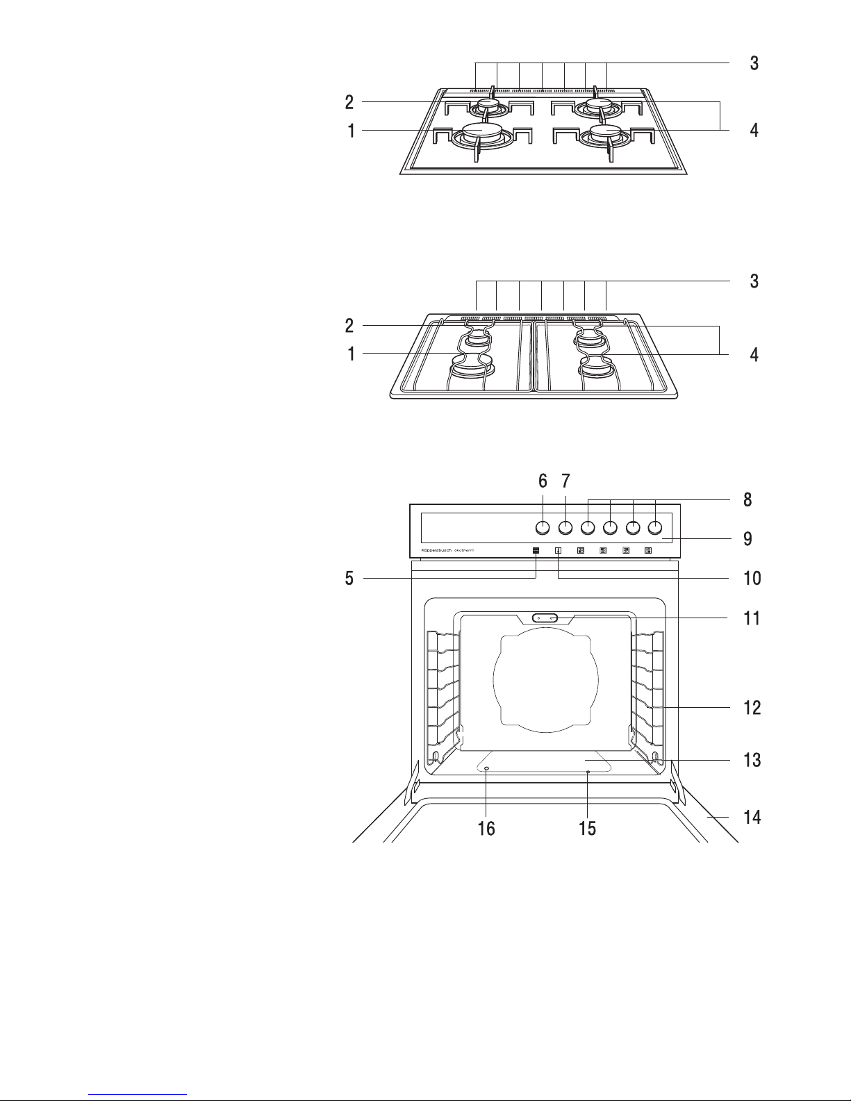
Your appliance at a glance
1 High speed ring
2 Simmering ring
3 Ventilation slits
4 Standard ring
5 Oven function indicator - eletric
6 Mode selector
7 Temperature control (oven)
8 Cooking zone controls
9 Control panel
10 Oven function indicator - gas
11 Plug contact with dummy plug for infrared grill
(acc. No. 545)
12 Side racks
13 Cover plate for oven burner
14 Oven door
15 Auxiliary ignition hole
16 Viewing hole
Accessories supplied:
Baking tray (aluminium)
Drip pan
Gridiron
Cross support for small pots
(only with glass ceramic hobs)
Optional accessories:
Cross support for small pots (acc. No. 160)
Grilling rack with lifter (acc. No. 125)
Pizza stone (acc. No. 145)
Gridiron (acc. No. 124)
Splash guard roasting tray (acc. No. 441)
Baking tray (aluminium) (acc. No. 542)
Drip pan (acc. No. 543)
backmobil
®
(acc. No. 600A)
Infrared plug-in grill (acc. No. 545)
Page 4
22 GEH 6300.0
Safety instructions
Connection and operation
■ Only one of the gas ring hobs supplied may be connected to this
Küppersbusch oven.
■ The gas cooker must be installed and connected in accordance with the
applicable conditions of installation.
■ The device may only be operated in well-ventilated spaces as gas flames
consume oxygen and cause a build-up of humidity and heat:
Keep at least one aperture such as e.g. a window or door open, or have a
ventilation system such as a cooking ventilation hood running in extraction
/ circulatory fan operating mode.
■ All work, such as connection to the gas mains or adjusting and converting
the appliance, should only be carried out by a qualified fitter. The legally
recognised regulations and the conditions for connection laid down by the
local gas board should be observed in all details.
■ Never use the appliance to heat a room.
■ In the event of any trouble during operation, immediately turn off the supply
of gas.
■ The appliance should only be serviced and repaired by a qualified technician
in accordance with the applicable safety regulations. Always ensure to
disconnect the appliance from the energy supply when repairs are being
carried out on facilities for directing the flow of gas. For your own safety,
do not allow anyone other than a qualified service technician to install,
service or repair this appliance.
■ If the cooker is run on liquefied petroleum gas (propane/butane) it is vital
to ensure that all joints between the gas bottle and the cooker are secure
and tight.
■ External flexible supply hoses should not be wedged into tight positions or
laid cross hot surfaces.
■ The surfaces of the cooker, the oven door and the appliance become very
hot in use. Always keep children away!
■ Make sure that trailing leads for kitchen appliances cannot become trapped
in the oven door.
■ Never use steam and/or pressure cleaners to clean the oven! Damage
caused to your appliance by cleaning it this way can make it lethally
dangerous.
■ Attention! The electronic one-hand spark ignition will not work if there is a
power failure. In such cases please use matches.
■ Do not lift the appliance by the handle of the oven door.
Cooking zones
■ The rings should not be ignited unless you are cooking something.
■ Always ensure that the plug-on rings and the burner tops are in the correct
position.
■ Overheated fats and oils may spontaneously ignite. Food involving the use
of fats and oils, e.g. chips, may only be cooked under supervision. Never
extinguish ignited fats and oils with water! Put the lid on, turn off the
cooking zone and remove the pan.
■ Always keep pressure cookers under observation until the right pressure has
been reached. First turn the burners of the rings up to maximum flame and
then (following the instructions of the manufacturer of the pressure cooker)
turn the heat down in good time.
■ The ventilation slits in the hob should not be covered over!
■ If the glass ceramic surface shows any signs of cracks, fissures or
breakage, switch off the appliance immediately and call Customer service.
Oven
■ When carrying out repairs and replacing oven light bulbs, the cooker must
be disconnected from the mains (switch off the fuse).
■ Do not spend more than 15 seconds attempting to ignite the oven flame
when the door is closed. If the attempt is unsuccessful after this time
period, open the oven door and ventilate for at least one minute before
trying again.
■ Never store any objects in your oven which could cause a hazard if the oven
is unintentionally switched on.
■ Take special care when working in the hot oven and always use an oven
cloth, oven gloves or similar protection.
■ When grilling (acc. No. 545), keep at least 5 cm distance from the grill.
■ The grill (acc. No. 545) is removable. Only remove it when the oven is OFF
and the grill has cooled down.
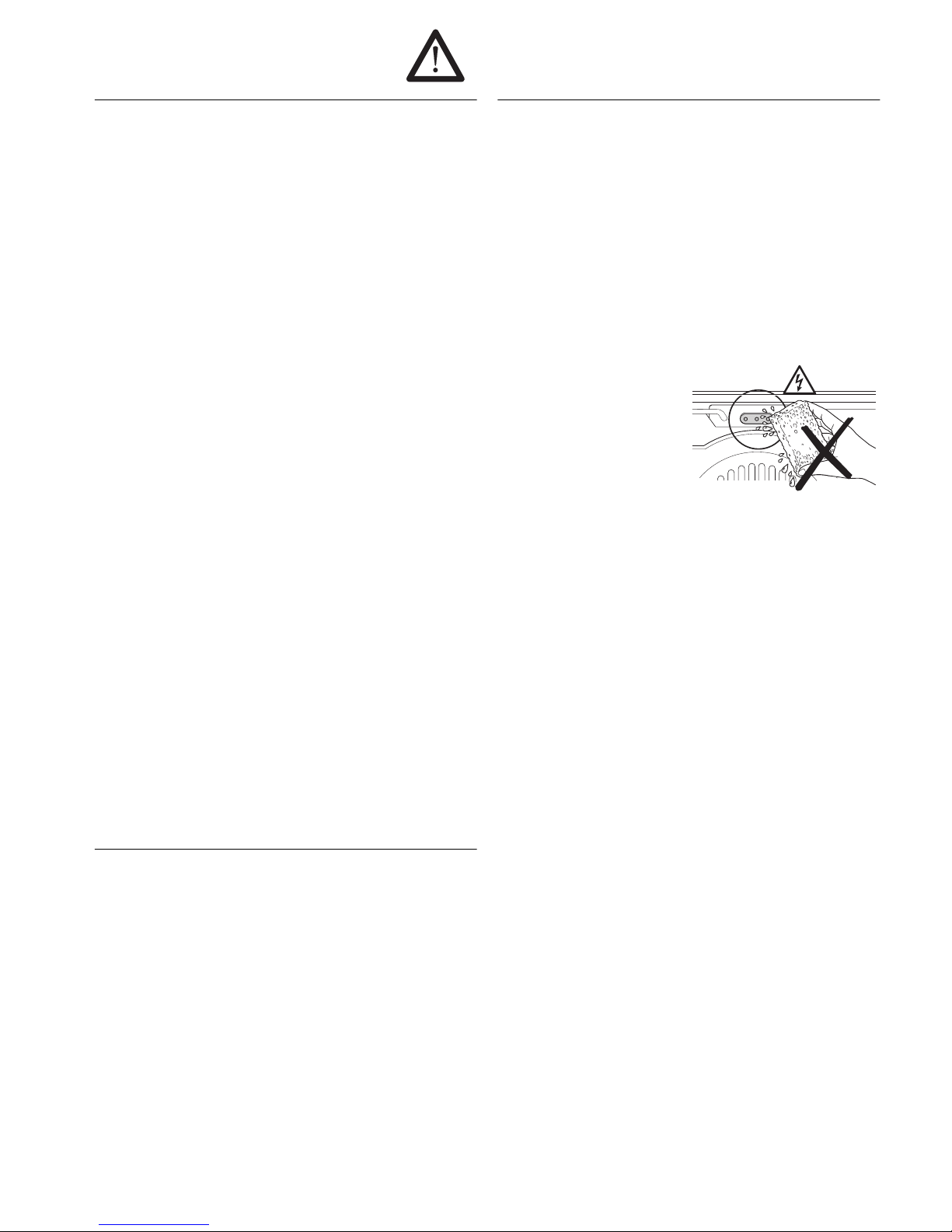
■ The oven must not be used or
cleaned with the grill socket open.
The dummy plug or the infrared
grill (acc. No. 545) must always be
inserted!
Treat it like any other socket:
Never wipe the socket and ensure
that no water or oven spray enters
it.
■ The oven door must form a good seal when closed. In the event of damage
to the door sealing, hinges, sealing surfaces or to the glass pane, do not
use your cooker until it has been repaired and checked by a qualified and
authorised trained installer.
■ During use, open and shut the oven door with care to prevent the burner
flames being extinguished.
■ Attention! When opening and closing the oven door, do not reach into the
hinge. Risk of injury!
■ Always close the oven door completely when preparing food in the oven.
Page 5
GEH 6300.0 23
Before using the appliance for
the first time
Disposing of the packaging and your old appliance
Please dispose of the packaging that came with your appliance in an
environmentally friendly way.
If you bought your appliance in Germany, the dealer who sold it to you will
take the packaging back for recycling. Recycling in this way saves on
resources and cuts down on waste. Your old appliance still contains useful
raw materials. Take your old appliance to a recycling collection point. Please
make your old appliances unserviceable before disposing of it, to prevent it
from misuse.
Initial cleaning
– Remove packaging and non-essential components.
– We recommend that you clean your oven before using it for the first time.
Clean the glass ceramic cooking area or hob, the oven interior, baking trays,
drip pan, gridiron etc. using a damp cloth and a little detergent.
– Heat the oven.
Close the oven door.
Pre-heat the oven using top and bottom heating elements at maximum
temperature for 60 minutes. The “brand new smell” that results can be
safely ignored provided the kitchen or other space in which the device is
installed is well ventilated.
Assembly of the infrared grill (acc. No. 545)
[
Switch the fuse off!
–Pull the dummy plug out of the rear oven wall.
–
- Plug in the infrared grill
into the plug contact.
Using the cooking zones
Please note the safety instructions on page 22!
Using the burners
The rated capacities of the various burners are given in the Table of Heat Input
“Table of heat input” on page 36.
Using the different types of burner:
The high-speed ring is used
-to sear meat,
- to bring large quantities of liquid to the boil.
The standard ring is used
- to prepare medium-sized portions of foods,
- to roast meat.
The simmering ring is used
- to keep food warm and to braise or stew it,
- to prepare smaller portions of food,
- to cook food that easily burns.
Switching the cooking zones on and off
Each cooking zone has its own control. All controls can be countersunk.
The symbols on the control panel indicate which regulator operates which
cooking zone.
The cooking zone burners are ignited by an electric spark. They can also be
lit with matches or something similar (e. g. in the event of power failure).
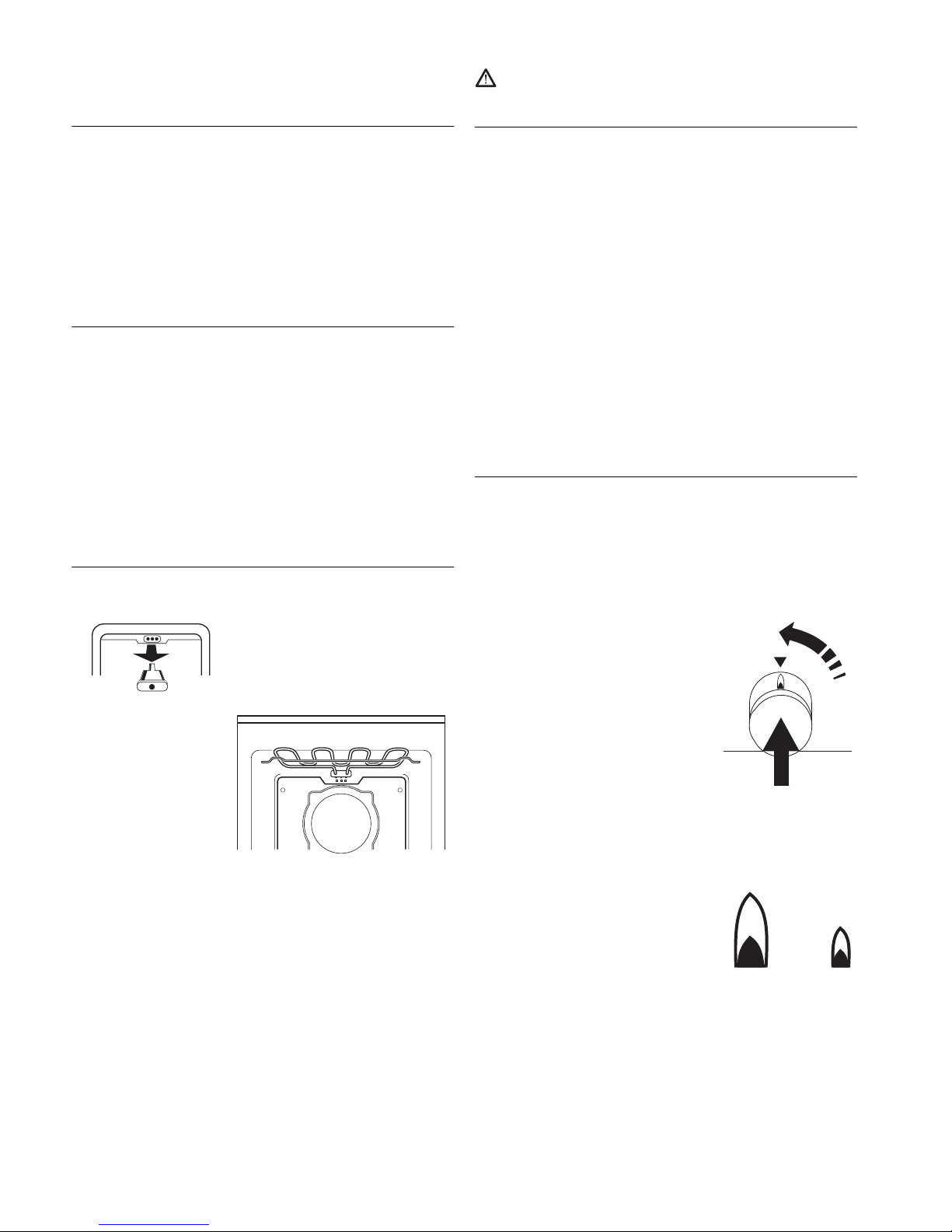
Igniting the cooking zone burners:
– Release the depressed cooking zone
regulator by pressing down.
– Turn the regulator anti-clockwise to the high
position and press in halfway, until a
resistance can be felt. The flame has been
ignited.
– Keep the cooking zone regulator depressed
for approximately a further 5 to 10 seconds
and then press it in again hard before
releasing it.
The flame is now burning.
If at any time the flame does not light successfully, allow about two seconds
and repeat the procedure. Press in the regulator a little bit longer and harder.
Adjusting the setting:
The maximum and minimum settings are marked
on the cooking zone controls. The burners can be
adjusted to any desired setting between maximum
and minimum.
– As far as possible, start cooking at the highest setting and continue at a
smaller setting.
Switching off the cooking zone burners:
– Turn the cooking zone control clockwise to zero setting.
F
All cooking zone burners are protected thermoelectrically. If at any time
the flame is extinguished unintentionally (e. g. due to pans boiling over
or due to a strong draught), the gas supply switches off automatically.
Page 6
24 GEH 6300.0
Cross support for small pots (only with glass
ceramic hobs)
The small pot cross
support can be installed
atop the simmering ring
on the pot support so that
small pots can be used
safely.
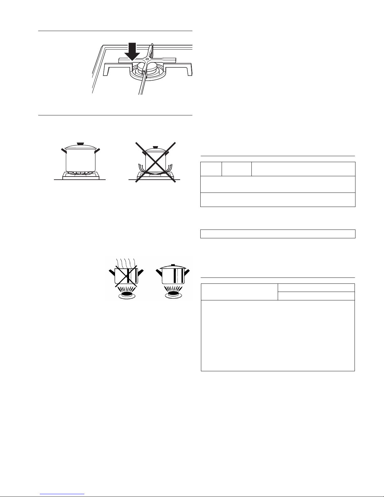
Which are the best pots and pans?
You can save time and power by choosing the best pans.
Choose a pot or pan whose diameter fits the burner size.
Make sure pots and pans are suited to the ring used. The flame should
completely cover the base. It ought not to exceed it.
Pot diameter recommendations:
High speed ring: 22 - 24 cm
Standard ring: 18 - 20 cm
Simmering ring*: 12 - 16 cm
* Small pots can be used on the simmering ring of the glass ceramic hob only
with the aid of the cross support.
Always make sure that the lid is on the saucepan.
The food will only boil over if the
flame is set too high. With a
little practice you will learn to
set the flame to just the right
heat so that the food will not
boil over, even when the lid is
on the saucepan.
Do not cook empty.
[
The use of spacers on the rings is not permitted for gas engineering
reasons.
The oven
[
Please note the safety instructions on page 22!
[
Attention. Risk of overheating! Do not cover the bottom of the oven
with aluminium foil and do not place pots or pans directly on the bottom
of the oven! This will trap heat and damage the enamel surface.
F
The controls are of the pop-out type and can be countersunk in every
setting. They pop out at a slight press of the finger. Adjustments cannot
be made whilst they are recessed.
F
The oven burner is protected thermoelectrically. If at any time the flame
is extinguished unintentionally the gas supply switches off automatically
and the oven function indicator - gas goes out.
However, when in use close the oven door with care to prevent the flame
being extinguished.
F
The cooling fan can continue to run after the oven has been switched
off, that is to say it switches itself back on because of the residual heat!
Symbols and operating modes
Following additional operating mode is possible with the accessory infrared
grill:
[
* If you turn the mode selector to “0”, the oven doesn't switch off. The
oven is in use as long as one of the two pilot lights is on.
Temperature settings
Dial
symbol
Operating
mode
Intended for
0*
OFF
!
Lighting
$
Top / Bottom
heat
Always set for the conventional operating mode using
Top and Bottom heat.
*
Grilling Surface grill for flat meat and slices and for gratinating
Temperature in °C Top/Bottom heat
Suitable for
260-280 Browning toppings
250 Baking pizza, baking
230 Baking
200 Baking, roasting, browning toppings
180 Baking, frying
160 Preserving
150 Baking
140 Meringues, honey cake
Page 7

GEH 6300.0 25
Igniting the oven burner
F
Only ignite the oven burner when the oven door is open.
F
The oven burner is ignited by an electric spark. It can of course also be
lit using a match or something similar at the auxiliary lighting port (B)
(e. g. in the event of power failure).
F
If at any time the flame does not light successfully, ventilate the oven,
then ignite once more.
– Release the depressed temperature control
by pressing down.
– Turn the regulator to the left to 280 °C and
press it in halfway until resistance is felt.
The flame will then be ignited.
– Hold the temperature control down for
another 5-10 seconds until the oven
function indicator - gas is illuminated.
– Press in the temperature regulator firmly
once more, before releasing.
The flame is now burning.
Selecting the temperature
– Reset the temperature control to the desired temperature.
The oven burner continues at maximum setting until the selected
temperature has been reached.
The size of flame only controls oven temperature when the oven is closed. If
the oven is left open, the flames automatically increase.
Selecting the operation mode
Selecting the operation mode:
with the mode selector (the switch
on the left)
Pilot lights
The oven function indicator - electric on the control panel is illuminated when
a function has been selected.
The oven function indicator - gas on the control panel is illuminated when the
oven burner has ignited and goes off about 20 seconds after the burner has
been switched off.
Rack levels
There are 8 rack levels in the side racks. These are numbered from 0 to 7,
from bottom to top. The drip pan, for example, can be positioned at position 0.
Side racks:
Rack level 0 is the lowest
possible level.
Oven trays
Baking trays:
■ Lift them slightly before taking them out of the oven.
When you put them back in the oven, make sure that the sloping edge of
the tray is pointing towards the oven door.
■ Slide the drip pan and baking tray with the two slots right to the back of
the oven.
Gridiron:
■ The crossbars on the racks
should point towards the back of
the oven (away from you).
Grilling rack with lifter to
insert in the drip pan (accessory)
■ The grilling rack is inserted in the drip
pan. Its lifter allows you to remove both
the tray and the drip pan together from
the oven. The drip pan remains in place
to catch any drips and you can easily
serve the food.
Splash guard roasting tray (accessory) for roasting and
grilling
■ The roasting tray is inserted in the drip pan and prevents the fat from
splashing out of the drip pan.
backmobil® (acc. No. 600A)
The backmobil® replaces the shelf
racks in your oven. You can slide it
out of the oven in one piece like a
trolley, and easily separate its
components for cleaning.
If your oven is fitted with a
backmobil
®
, please read the
instructions that came with it.
Roasting
F
Use the drip pan and the gridiron.
F
Turn the meat over after 2/3rds of the cooking time.
■ Only cook meat or fish in the oven if the item weighs over 1 kg.
■ Cooking time depends on the type of meat, its quality and its thickness.
To measure the joint, lift it slightly, as a joint tends to compress under its
own weight.
■ A layer of fat around the joint can double the cooking time.
■ If you are cooking a number small pieces of meat or poultry in the oven,
increase the cooking time by about 10 minutes for each additional piece.
For example, the time needed to roast a chicken is normally about
60 minutes. To cook 2 chickens, cook for 65 to 75 minutes.
F
Be sure to follow the guidelines for shelf positions.
For meat, insert the tray at level 3 and the drip pan in level 2.
Roasting in a pan (oven)
■ We recommend that you roast leaner types of meat in a covered roasting
pan (e.g. roast veal, braised beef or frozen meat) to retain the meat’s juices.
■ You can use any type of heat-resistant pan (stainless steel, enamel, cast
iron or glass) as long as it does not have a plastic or wooden handle.
■ If you use a cooking brick, follow the manufacturer’s instructions.
We recommend the following procedure:
– Rinse the pan with water or grease it lightly.
Page 8

26 GEH 6300.0
– Season the meat as required and place in the pan. Put the lid on the pan
and place the pan in the cold oven.
– Select Top/Bottom heat $ and set the temperature to between 180 and
200 °C.
Make your gravy in the usual way.
Guidelines for roasting
*whole chicken 45 - 60 min.
Baking
Baking tins
Always place in the middle of the grill. Tins should not overlap the edges of
the grill. Place square tins crosswise.
Use light-coloured tins for baking if possible.
F
Bake only on one level.
Tips on the table “Guidelines for baking”
The table in the next column contains a selection of cakes etc., the necessary
temperatures, cooking times and rack levels.
■ A temperature range is given, since the optimum temperature depends on
the recipe you are using for the dough and the size and shape of the item
you are baking.
■ We recommend that you use the lower temperature to start with, increasing
it only if you want a deeper brown or if baking is taking too long.
■ If you are not sure how to bake your own recipes, select a similar one from
the table and use the temperatures and baking times as a guide.
■ Food that is dissimilar in height will brown differently at the beginning.
Please do not change the temperature setting, because this will even itself
out as baking continues.
■ Baking moist cakes can produce steam, which forms condensation in the
oven. Most escapes through the vapour channel and can collect on kitchen
tiles and fronts of units as condensation. This is physically necessary.
Guidelines for baking
The recommended temperatures for the preferred operating modes are
highlighted.
Please observe the notes concerning this table in the last column!
Type of meat Top heat/bottom heat $Roasting time
Temperature in °C per cm of the thickness
of the joint in mins.
Joint of beef
170-190 18
Roast beef
200 – 220 10 – 12
Fillet
200 – 220 8
Veal
170 – 180 12
Roast pork
170 – 190 12 – 15
Smoked loin of pork
170 – 190 8
Game
170 –190 15
Wild boar
170 – 190 15
Fillet of game
200 – 220 8 – 10
Mutton
170 –190 15
Duck
170 –190 12
Goose
170 –190 12
Chicken
180 – 200 8
Turkey
170 –190 12
Fish
200 – 220 8
Type of cake or biscuit
Top heat/bottom heat $ Baking time
rack level Temperature in °C in minutes
Cake mixture
Ring cake 2 170-180 50-65
Tin cake 2 170-180 50-70
Madeira cake 2 160-170 60-70
Gateaux and flans 2 170-180 40-65
Flan bases 2 170-180 25-35
Fine fruit flans 2 170-180 45-60
Small biscuits 2 170-180 15-30
Large flat cakes:
with a dry topping 2 170-180 25-35
with a moist topping 2 170-180 35-60
Kneaded dough
Flan bases 2 180-200 25-35
Cheese cake 2 160-170 70-100
Small bisquits 2 170-180 15-35
Large flat cakes:
with a dry topping 2 170-180 25-35
with a moist topping 2 170-180 35-60
Leavened dough
Ring cake 2 170-180 40-65
Yeast cake 2 170-180 40-50
Rich sweet bread (preheated) 2 175-180 50-70
Small biscuits 2 170-180 15-30
Large flat cakes:
with a dry topping 2 170-180 25-35
with a moist topping 2 170-180 33-60
Sponge cake
Gateaux and flans 2 175-180 30-40
Rolls 2 190-200 12-20
Biscuits made with white of egg
Meringue 3 140 60-70
Cinnamon stars 3 150-160 15-20
Macaroons 3 150-160 20-40
Other doughs
Puff pastry 3 200-220 15-30
Puff pastry made with leavened
dough
3 200-225 30-40
Puff pastry made with curd
cheese
3 200-225 30-40
Choux pastry 2 200-220 30-40
Dough made with curd cheese
and oil
2 170-180 25-35
Honey cake 2 140-150 20-35
Bread and pizza
Leaven and bread made with
yeast (preheat: 230 °C,
prebake: 10 min., 230 °C)
2 180 50-60
Bread made with yeast/white
bread.
2 200 30-50
Pretzels (preheat: 230 °C) 2 220 15-20
Pizza (preheat: 250 °C) 1 250 8-12
2 baking trays with Pizza (pre-
heat: 250 °C)
1 und 3 250 10-14
Page 9

GEH 6300.0 27
Grilling (only with accessory 545)
[
Always close the oven door when grilling.
– Set the mode selector to Grill*.
The oven function indicator - electric
on the control panel illuminates.
F
Temperature regulator stays at 0.
– Always close the oven door when
grilling.
– Preheat the oven for 5 to 10 minutes.
– Put the drip pan with roasting tray into the 1st rack level from the bottom
and the gridiron into the rack level as per the table.
Cleaning and maintenance
You should carefully read this chapter before you use your appliance the first
time. If cleaned correctly and looked after regularly the appliance will remain
beautiful and clean for many years. The following tips will help you to clean
and care for your oven's various surfaces gently but thoroughly.
For all surfaces
[
Do not, under any circumstances, use steam or pressure cleaning
machines to clean the appliance! Damage caused to your appliance by
cleaning it this way can make it lethally dangerous.
[
Risk of burning! Make sure the appliance has cooled down before
cleaning.
[
Please follow the instructions provided with the cleaning agents you plan
to use.
Clean the oven each time you use it. Dirt left will burn into the surface next
time you use it. These burned on residues can sometimes be impossible to
remove completely.
To clean an oven that is not very dirty, use a damp cloth, a soft brush or a
soft sponge and a weak solution of detergent and warm water. Always rinse
the surfaces with cold water to remove all traces of detergent. Detergent
residues can cause discoloration and blotches. Wipe dry afterwards.
F
The following pointers will help you to carry out a more thorough cleaning
of the various parts of your oven.
F
VSR O-FIX-C is perfect for the cleaning of glass ceramic, enamel and the
coated inside of the door. This cleaning powder is available from
KÜPPERSBUSCH Customer Service.
Do not use any
- aggressive or bleaching cleaning agents containing for example active
oxygen, chlorine or corrosive components.
- abrasive cleaning or scouring agents, such as steel wool, soap-impregnated
steel wool, stiff brushes, metal or plastic sponges or any similar cleaners
with an abrasive surface.
Removing fat and grease deposits
First, soak any heavy deposits to loosen them. A wet cloth is ideal. This will
make them easier to remove later.
Information about the cleaning scraper
[
Caution! Risk of cutting! The blade of the cleaning scraper is very sharp!
Always hold the cleaning scraper flat to the surface
and push the grease away from you
[
Do not scratch the surface with the edge of
the scraper and take care not to damage the
sealing with the edge.
Suggestions on the use of oven sprays
[
Please follow the manufacturer's instructions carefully.
Oven sprays attack aluminium, paint and plastic!
For environmental reasons you should not use oven spray at all. If you
nevertheless want to use it, only spray it in the oven interior and on enamel
baking trays.
Dish Rack
level
Grill
F
1st side 2d side
in minutes
Pork chops/Escalope 6 6-8 4-6
Fillet of pork 5 10-12 8-10
Sausages 6 6-8 4-6
Shashlik 4 7-8 5-6
Rissoles 4 8-10 6-8
Beef steak 6 4-6 3-5
Slices of liver 6 3-4 2-3
Escalope of veal 5 5-7 4-5
Veal steak 5 6-8 4-6
Mutton chops 5 8-10 6-8
Lamb chops 5 8-10 6-8
Half a chicken 3 10-12 8-10
Fillet of fish 6 6-7 4-5
Trout 4 4-7 3-6
Toast 5 2-3 2-3
Toasted sandwiches 4 6-8
Page 10

28 GEH 6300.0
Enamel
Oven interior, front, baking trays, drip pan, enamel hobs
Some plastic sponges with abrasive side can be used. Some products do
however contain grains in the abrasive side of the sponge which can cause
scratches.
Carefully test a small area that is out of sight.
F
The type of scraper normally used for glass-ceramic surfaces is suitable
for removing heavy dirt.
F
We recommend VSR O-FIX C for thorough cleaning. Oven spray may be
used - however not on an enamel hob!
Stainless steel
Stainless steel door front, control panel, backmobil (acc. No. 600A)
[
Stainless steel is very easy to scratch!
Do not use a scraper!
[
Remove any calcium, grease or starch deposits right away. They will stain
the surface!
We recommend that you use a proprietary stainless steel cleaner.
We recommend cleaning the stainless steel surfaces weekly with a proprietary
stainless steel cleaner. This will create a protective film that protects the
surfaces from discoloration.
Glass
Door interior – coated glass
[
Avoid using oven spray if you can. If used regularly, an oven spray will
attack the coated surface of the glass.
The type of scraper normally used for glass-ceramic surfaces is suitable for
removing heavy dirt.
F
We recommend VSR O-FIX C or glass cleaner for thorough cleaning.
Door front, control panel
F
Clean the oven front with a weak solution of detergent and warm water,
using a damp cloth or a soft sponge. Do not use a glass cleaner.
Glass ceramic hob
First remove heavy dirt and food residues with the cleaning scraper when the
cooking surface is still warm.
Clean the cooled down cooking surface with water and a small amount of
detergent, with a cleaning agent for glass ceramic surfaces or with
VSR O-FIX-C. Wipe off the surface with clear water then dry it thoroughly.
F
Residues of cleaning agents can cause discolouring the next time you
switch it on. Cloths and sponges which are used for the cleaning of other
surfaces can cause discolouring.
F
Weekly cleaning with cleaning agent for glass ceramic surfaces protects
against discolouration and can often remove stains and resistant dirt.
Burners
F
Burner covers and attachments can be put in the dishwasher.
Clean the burner covers and the attachments with hot soapy water. Allow both
parts to dry before you replace them.
Take care that attachments and burner covers are replaced correctly after
cleaning. Engage burner covers by turning.
Knobs
Clean the knobs with a weak solution of detergent and warm water, using a
damp cloth or a soft sponge.
Removing and refitting the oven door
Removing the oven door
– Open the oven door as far as it will
go.
– Fold up the clamps on the door
hinges.
– Take hold of the oven door on both
sides and close it slowly.
– When the oven door is about half-
closed, the hinges will fall out of the
catches.
– The oven door can now be removed.
Reassembling the oven
door
– Grasp the oven door at both sides
and slide the hinges into the
openings on the oven.
– Slowly open the oven door until it
is fully open.
– Fold down the clamps on the
door hinges.
– Close the oven door.
Removing and refitting the side racks
Removing the side racks.
– Undo the screws.
– Take out the racks.
Refitting the side racks
– Insert the side racks and screw
into place in front.
Page 11

GEH 6300.0 29
What to do if trouble occurs...
[
Repairs must be carried out by a qualified service engineer!
But there are some problems that you can fix yourself. You should first check
that you are using the oven correctly. Repairs during the guarantee period are
chargeable, if they are caused by user error or non-observance of the following
instructions:
Replacing the oven lamp
[
Caution! Danger of electric shock! Disconnect the oven from the mains
before you open the oven lamp cover. Switch off or pull out the fuse!
[
Allow the appliance and the lamp to cool before changing the lamp. If
the oven has been used recently, the lamp will be hot!
Type: 25 W, 230/240 V, fitting: E14
Important: bulbs must be heat-resistant up to 300 °C!
These lamps are available from KÜPPERSBUSCH Customer Service or from
your dealer.
[
If the fitting has become solid due e.g. to dirt or long use then glass may
splinter during removal. Hold a towel or cloth over the fitting to catch any
splinters.
Changing the light bulb
– Unscrew the shelf rack.
– Carefully lever out the glass
cover with a screwdriver.
– Remove the faulty light bulb
and screw in the new one.
– Replace the glass cover.
Rating label
Should you need to contact Customer service or order spare parts, always
quote the information printed on the model identification plate.
The oven's identification plate is located just
inside the oven on the right hand side and is
visible when the door is open.
– Make a note of this information before you
consult Customer Service.
Fault Cause Remedy
Oven and cooking zones will
not ignite.
Power and/or gas
supply interrupted.
Check fuses. Is the mains
plug in the wall socket?
Check gas supply.
Cooking zones will not
ignite.
Food remains or
cleaning agent
between the spark
ignition and the
burner.
Release carefully and clean.
Spark ignition
defective.
Call Customer Service.
Light with matches in the
meantime.
Plug-on rings, burner
cover, spark plug and/
or thermal probe wet.
Dry thoroughly, or allow to
dry.
The cooking zone or the
oven does not ignite - no
igniting sound can be heard.
The knob is loose - it is
pushed down and positioned slightly in front
of the panel.
Press in the knob firmly, it
will then turn back into the
right position.
[
Do not let the knobs
snap out, they could
loosen from their fastening device and no longer ignite.
The flame of the burners
suddenly changes.
Plug-on rings or burner
tops are skew.
Shift plug-on rings or burner
tops until they click into
place.
Plug-on rings, burner
cover, spark plug and/
or thermal probe wet.
Dry thoroughly, or allow to
dry.
Flames go out when set low
if a drawer or cupboard door
is closed.
Poor ventilation system
due to improper
installation siting.
Please request
Küppersbusch Customer
Service to supply a solution.
The cooking zone control
suddenly needs to be held
down longer until the flame
ignites.
Temperature sensor
bent.
Carefully bend the
temperature sensor back into
the correct position.
Plug-on rings or burner
tops are skew.
Insert plug-on rings / burner
cover properly so they click
in place.
Plug-on rings, burner
cover, spark plug and/
or thermal probe wet.
Dry thoroughly, or allow to
dry.
Oven does not heat up. Temperature control
and/or mode selector
have not been
switched on.
Set temperature control and
mode selector as required.
The flame has gone
out.
Reignite.
Oven light no longer works. Blown lamp. Replace the oven lamp.
Oven door glass cracked. Switch off the appliance; call
Customer Service.
Oven door will not shut. Door or door sealing
dirty.
Clean door and sealing using
only warm soapy water and a
damp cloth.
Fruit juice or egg white
stains on enamel parts.
Moist cake or meat
juices.
Harmless changes in the
enamel, cannot be remedied.
Oven production number
Oven model type
Model designation hob
Page 12

30 GEH 6300.0
Installation instructions for fitter
Safety instructions
Please heed the safety instructions on page 22!
■ Important! The gas category permitted for the connection of the appliances
can differ from region to region. In case of doubt enquire at your local gas
board to find out which categories of gas come into question. Check whether
the data on the rating label are in accordance with the local connection
conditions (type of gas and gas pressure) and with the appliance setting. If
there are any discrepancies the appliance must be converted accordingly! All
settings for the appliance are stated in this user guide. This appliance
should not be connected to a pipe for extracting combustion products.
■ When connecting the appliance to the gas mains you should particularly
observe the relevant regulations and guidelines of the institutions of the
country where the appliance is operated. In Germany and Austria these are:
DVGW-TRGI 1986 Technical guidelines for gas installations (Germany)
TRF 1988/1996 Technical guidelines for liquefied petroleum gas (Germany)
ÖVGW-TRGI and TRG 2, part 1 Technical guidelines (Austria)
You should also observe the regulations of the local gas supply companies
and those stipulated by the authorities (e.g. fire protection regulations).
■ The appliance should only be connected and put into operation by a
qualified gas fitter who should also be the only person to carry out any work
such as maintenance and repair or adjustment and conversion. The legally
recognised regulations and the conditions for connection laid down by the
local gas board should be observed in all details.
Work which has been improperly carried out endangers the safety of the
user!
■ This appliance should not be connected to a pipe for extracting combustion
products. It must be installed and connected in accordance with the
applicable conditions of installation. Particular attention should be paid to
sufficient ventilation measures.
■ If the connection plug should not be accessible, protect the appliance by
line-protecting switches, fuses or contactors whose contact opening has a
width of at least 3 mm.
■ When making any repair, ensure the appliance is electrically dead using the
devices above and cut off the gas supply.
■ The appliance is supplied ready to plug in. It should be connected only to
a properly protected wall socket. Installing and wiring a socket or replacing
the connection cable should only be performed by an electrician and in
observance of the relevant regulations.
■ The socket for plugging in the unit must be outside the installation space.
■ The ventilation openings must not be covered over.
■ When converting from natural gas to liquefied petroleum gas, it is always
necessary to change the main injectors and the low flame injectors. Only
special injectors supplied by Küppersbusch Customer Service may be used.
This also applies if the reverse is the case. This conversion should only be
carried out by a qualified gas fitter.
■ Any conversions to different types of gas must be permanently marked on
the nameplate of the appliance. Always use only the labels supplied with
the special injectors.
■ No changes may be made to the appliance unless with the express approval
of the manufacturer.
■ Ensure that all live connections are safely insulated when installing the oven.
Conditions for building in the appliance
■ The installation space must have a volume of at least 20 m
3
and it must
be possible to ventilate the area by a window or a door opening out into
the fresh air.
■ Additional space in an adjacent cupboard is needed for the gas connection.
■ The wall connection strip should be made of heat-resistant material and must
not be provided with sockets in the area around the hob. We recommend
using a support strip made of plastic and a covering strip made of aluminium.
The lateral part on the worktop must not be longer than 30 mm.
■ The wall above the wall connection strip in the area around the appliance
must be made of non-inflammable material. Wood, plastic, PVC foil etc. do
not meet this requirement.
■ In normal use adjacent furniture may be subjected to increased
temperatures. Such furniture must comply with the relevant legal and
technical requirements. The plastic finish or the veneer of built-in kitchen
furniture must have been produced using a heat-resistant adhesive
(100 °C).
■ Lateral distance to high cupboards on both sides must be a minimum of
300 mm.
■ Minimum distance to adjacent wall cupboards hung high and exhaust hoods
above the oven is 650 mm.
■ Before installation and after every removal of the hob, make sure sealing is
undamaged and sits tight. If not, replace it/them. Do not use silicone or the
like for additional sealing as this presents a risk of the coated cooking
surfaces being damaged when the hob is removed.
Exception: Uneven surfaces (e.g. ceramic tiling), where sealing with
temperature-resistant permanently elastic material is necessary (e.g.
silicone suitable for ceramics). This sealant may only be applied around thee
hob edges and never underneath it.
Planning the supply lines
Threaded appliance joint: R ½" ISO/R 7-1
The required gas connection R ½" must be connected in accordance with the
current statutory installation conditions and guidelines of the country in question. In Germany, a gas connection may be carried out either as a fixed connection with a gas shutoff valve or using an officially-approved gas safety pipe
with a socket.
Take the following into account when planning the supply lines:
Gas connection with flexible gas safety hose
The joint must be provided with a stop cock and must be accessible. It is
recommended to have a safety gas outlet in the right-hand cabinet. A flexible
gas safety hose, 800 mm in length (as per DIN 3383) is screwed directly onto
the connection points of the hob and screwed on tightly so that no gas
escapes.
If connecting from the left-hand cabinet it is necessary to have a flexible gas
safety hose. Length: max. 1.50 m!
Gas connection to immobile fitting
The joint must be provided with a stop cock and must be accessible.
Electrical connection
Electrical connection must be carried out in accordance with national and local
regulations. For the power supply to the oven and the electric automatic spark
ignition a 230-240 shockproof socket is required well away from the
installation site. The appliance is supplied ready to plug in.
Page 13

GEH 6300.0 31
Installing in a fitted kitchen unit
The cooker must be installed absolutely
horizontally.
F
We recommend sealing the rear areas of the installation facing the wall
and adjacent high cupboards. This prevents cooking flames going out
under unusual ventilation conditions should drawers and/or cupboard
doors in adjacent furniture not be closed carefully.
Preparing the built-in cupboard
– In the upper area of the side wall of the cupboard cut out an opening
measuring 100 x 100 mm for the supply lines.
[
Note the niche dimensions! A gap of at least 5 mm must exist between
the inbuilt oven and the cooking hob to ensure adequate ventilation.
F
Important: Remove the back wall of the cupboard and the crossbar
between the side walls, if applicable!
Cutting out the openings in the worktop
■ Important: Do not mark out the opening in the worktop unless the worktop
is already properly fitted.
■ The working surface must be installed horizontally and the opening must be
cleanly cut.
■ No cross-bars may be in the area of the cut-out underneath. They have to
be reduced at least to the opening size of the worktop. Completely remove
the front cross bar!
The appliance comes supplied with a template for marking out the opening in
the worktop.
Place the template against the
front edge of the cabinet.
Mark out the opening for the
cooker in the worktop and cut
out.
Seal the cut sections
– The cut sections should be sealed with a water-repellent protection paint.
Checking or replacing the sealing
– Make sure that the sealing of the hob is properly seated.
Use temperature-resistant permanently elastic sealant around the hob edges
on uneven surfaces (tiling, etc.).
– Do not apply this sealant under the hob on the work surface/s, as this/these
would then be damaged during any later removal.
Remove transport securing devices.
– The plastic clips used to secure the burner covers and burner tubes are to
be removed.
– The burner covers and intermediate rings are to be removed from all four
burners.
– The two front burners are screwed onto housing sheets to secure them in-
transit. Undo the screws.
Preparing the gas connection
Check that the details on the nameplate (see page 29) are the same as the
type of gas used in your area. If there are any discrepancies, the hob will have
to be converted for the corresponding type or quality of gas (see page 34).
Screw the gas safety hosing tight
to the oven connection using two
open-jawed spanners by
counter-tensioning.
[
Make sure nothing near the
piping is bent. If this
happens the knobs won’t fit
properly!
Sliding the appliance into
place
Insert the appliance a short way into a
cupboard alcove.
Pull the supply lines through the
opening in the side wall.
Now slide the oven all the way into its
space.
[
Do not bend, jam, tension or fold
the gas connection piping / hosing
when doing so!
Fastening in the appliance
– Open the oven door.
– Using the screws provided and
slanting them outwards, fasten
the appliance to the cabinet.
Readjusting the retractable knobs!
After the appliance has been connected and fitted the knobs must be checked
to see whether they work in different positions.
If, on account of connecting to the gas supply or fitting into the kitchen units,
the knobs no longer work perfectly, the following steps should be taken:
– remove both middle knobs;
– loosen the screws next to the valve shaft, which are visible through the knob
opening;
– using a screwdriver to raise or lower the valve shafts through the knob
opening, align the handle shaft with the centre of the hole and then
retighten the screws using a second screwdriver;
– replace the knobs and check again.
Page 14

32 GEH 6300.0
Installing the glass ceramic surface
F
When installing stone worktops the glass ceramic surface cannot be
fastened with clips. See page “Special case: Installing glass ceramics
surface in a stone work surface” page 32.
F
The parts are not assembled when delivered.
Drive in the clips
– Align the clips carefully and drive them in with a hammer.
Worktops with more than 30 mm
thickness:
With worktops with 30 mm
thickness the clips have to be
screwed down with two screws
(not supplied)!
– Attach the separate fume duct on the rear of the worktop recess with the
enclosed screws 4.2 x 16 mm.
Clipping the glass ceramic surface in place
– Now lay the surface down, align it and clip it in place.
[
The glass ceramic surface must rest evenly in the opening. If the strain
of the glass ceramic surface is too great the appliance can crack when
heating up.
F
If the glass ceramic surface is not fixed tightly
in the opening it is slightly too big. In such
cases, screw the clips tight using two screws
each (not supplied) and bend the retaining
devices outward a little to increase spring
tension.
Installing the burners
– Raise the burner with the tool
provided and move it into
position.
– Screw on the holding sheet for
the burner.
Special case: Installing glass ceramics surface in a stone
work surface
In these cases, the clips are not screwed to the cutout but to the hob.
for 30 mm work surfaces
for 40 mm work surfaces
– Insert the cooking area
surface edge at the back
and carefully lower it. Use
manual pressure on the
clips here.
– Press the cooking area
surface down until it is
entirely in contact atop the
working surface.
F
If the cutout in the work surface is a little too big it is possible to bend
the clip retainers outward to increase spring tension.
Page 15

GEH 6300.0 33
Installing the hob
– Attach the separate fume duct on the rear of the worktop recess.
– Insert the support frame and fasten with six screws 4.2 x 16 mm.
– Position the hob loosely.
– Raise the burner with the tool provided, position and screw on with three
screws 4.2 x 16 mm and washers in the holes with the thread collar visible.
– Then align the hob and fasten to the appliance with screws 4.2 x 32 mm
and washers through the remaining free hole at each burner location.
Assembling the burners
– Assemble the burner:
Place the burner cover and
attachment carefully in the
correct position.
– Turn the cover to bring into
position.
Checking the supply lines
Power supply
■ Check the installation of the connection cable. It must not be tightly wedged
in, pass across the cooker or be located at a ventilation channel.
Gas supply:
■ Check that all joints are tight and secure. The hoses must be installed in
such a way that they are at a safe distance from hot surfaces.
The hoses must not be tightly wedged in!
Checking the ring burners
– Ignite the burner and check that it is burning steadily.
– The flame should be steady.
[
Check whether the flames keep burning at low setting if doors / drawers
in adjacent furniture are opened / closed. If they go out, the rear of the
installation must be sealed due to poor ventilation. A solution to this
problem can be requested of Küppersbusch Customer Service.
Checking the oven burner
– Ignite the burner and check
that it is burning steadily.
– Heat the oven at the highest
temperature level for at least
10 minutes and then turn it
down to the lowest
temperature level. The burner
should burn with a small, but
steady flame.
Check air adjustment using the
table below if necessary and
then re-set.
The flames should burn
steadily, but not as strongly as those of the ring burners.
Guidelines for the air setting
Natural gas H, E, E+ 3.0 mm
Natural gas L, LL 1.0 mm
Liquefied petroleum gas 50 mbar 2.5 mm
Liquefied petroleum gas 30/37 mbar 3.0 mm
Cover
Attachment
Page 16

34 GEH 6300.0
Factory setting / conversion possibilities
This appliance can be converted to run on other types of gas.
[
Adjustment and conversion work should only be carried out by a qualified
gas fitter! The applicable rules and regulations should be observed.
Disconnect the appliance from the power supply so that it is completely
free of voltage.
[
The type of gas and the gas supply pressure must correspond to the gas
setting specified on the appliance. The factory setting is indicated on an
information plate or on the identification plate.
[
Any subsequent conversions to different types of gas must be
permanently marked on the nameplate of the appliance.
[
Only use special injectors obtained from the Customer Service.
Conversion injector sets
Injector table
Converting ring burners
Main injectors
If the ring burners are set to run on a different type or quality of gas the main
injector must be replaced.
– Remove the burner cover and plug-on accessories.
– Use a socket wrench to unscrew the injector.
– Place the new injector into the socket wrench and screw it in as far as it
will go.
Low flame injectors
After you have removed the control knobs (for the rings and the oven) and
removed the control panel (see below) the low flame injectors can be adjusted
or reset. If you are using natural gas and liquefied petroleum gas the low flame
injectors must be changed. Screw in the injectors as far as they will go (see
Injector Sets table).
– Disconnect the appliance from the
power supply (unplug from the mains
or switch off the fuse).
– Remove the control knobs (for rings
and oven).
– Open the oven door.
■ Important: The control panel remains
connected to the appliance due to the electrical wiring. It must therefore be
handled with care!
– Unscrew the two screws on left and
right under the control panel and the
two behind it.
– Lift the control panel towards the front
and, holding it by the lower edge,
draw it slightly towards the front and
carefully remove it by lowering it
downwards.
– Unscrew the low flame
injectors
replace them and screw
the new ones in as far as
they will go.
Gas type, pressure Injector sets
Natural gas H, E, E+, G 20 (20/25 mbar) on demand
Natural gas L, LL, G 25 (20 mbar) acc. No. 219
Natural gas L, G 25 (25 mbar) on demand
Liquefied petroleum gas butane/propane,
G 30 (50 mbar)
acc. No. 211
Liquefied petroleum gas butane/propane,
G 30 (28-30/37 mbar)
acc. No. 218
Liquefied petroleum gas propane, G 31 (50 mbar) on demand
Gas type, pressure High speed ring Standard ring Simmering ring Oven ring
Main
injector
Low setting
injector
Main
injector
Low setting
injector
Main
injector
Low setting
injector
Main
injector
Low setting
injector
Natural gas H, E, E+
G 20 (20/25 mbar)
125569347724115077
Natural gas LL G 25 (20 mbar) 145 62 117 52 79 47 165 82
Natural gas L G 25 (25 mbar) 118 61 104 49 78 44 155 80
Liquefied petroleum gas butane/
propane G 30 (50 mbar)
73 34 62 26 49 23 82 44
Liquefied petroleum gas butane/
propane G 30 (28-30/37 mbar)
81 39 70 28 53 24 92 52
Liquefied petroleum gas propane
G 31 (50 mbar)
79 36 67 30 51 26 89 48
Page 17

GEH 6300.0 35
Resetting the oven burner
Main injector
When resetting the oven burner the burner injectors must be replaced.
– Loosen the cover plate.
– Then detach the air slide and the oven burner.
– Set the parts aside and unscrew the burner injector using a socket wrench
of type SW 14.
– Screw in the new injector as shown in the Injector table.
– Reinsert the burner and screw it down tightly.
– Adjust the air using the table below.
– Heat the oven at the highest temperature level for at least 10 minutes and
then turn it down to the lowest temperature level. The burner should burn
with a small, but steady flame.
Readjust the air if necessary.
The flames should burn steadily, but not as strongly as those of the ring
burners.
Guidelines for the air setting
Low setting injector
The readjustment is carried out at the oven thermostats (oven temperature
control). The control panel must first be removed. (See “Low flame injectors”).
For natural gas and liquefied petroleum gas
Unscrew the injector and replace it by the new injector. Screw in the new
injector as far as it will go.
Finally, check burning behaviour.
Final assembly
On completion of the conversion and setting work, final assembly can be
performed.
■ Once correctly installed the device is to be protected on all sides by covers
so that contacting any operationally insulated part is impossible.
■ The cover may only be removed by tools.
– Mount the control panel.
– Install the knobs for regulating the
cooking rings and the thermostat that
controls the oven.
Natural gas H, E, E+ 3.0 mm
Natural gas L, LL 1.0 mm
Liquefied petroleum gas 50 mbar 2.5 mm
Liquefied petroleum gas 30/37 mbar 3.0 mm
Page 18

36 GEH 6300.0
Technical data
Table of permitted gas types and gas pressures
Table of heat input
Total nominal heat input = 11.7 kW
Connected load of the appliance = 843 g/h
Electrical connection
Connection standard mains plug into a wall socket.
Power consumption at 230 V: 2.5 kW,
at 235 V: 2.6 kW
Power supply 230-240 V, 50 Hz
Fuse rating 16 A
Gross calorific values according to EN 437
The HSB calorific value can be obtained from the relevant gas supply company
upon installation.
The flow rate is calculated as follows:
heat input kW x 1000
Flow rate l/min = --------------------------------------
gross calorific value kWh/m
3
x 60
Country
(ISO abbreviation)
Natural gas
H, E
(G 20)
Natural
gas LL
(G 25)
Natural gas
L
(G 25)
Pressure couple
natural gas E+
(G 20/25)
Propane
(G 31)
Pressure couple
(butane/propane)
(G 30/31)
Butane
(butane/propane)
(G 30)
Category
mbar mbar mbar mbar mbar mbar mbar mbar
Germany (DE)
20 20 50 II
2ELL3B/P
Denmark (DK)
Finland (FI)
Sweden (SE)
Iceland (IS)
Norway (NO)
20 28-30 II
2H3B/P
Netherlands (NL)
25
25
50
28-30
II
2L3P
II
2L3B/P
France (FR)
Belgium (BE)
20/25 28-30/37 II
2E+3+
United Kingdom (GB)
Spain (ES)
Italy (IT)
Portugal (PT)
Ireland (IE)
Greece (GR)
20 28-30/37 II
2H3+
Austria (AT)
20 50 II
2H3B/P
Luxembourg (LU)
20 28-30/37 I
2E, I3+
Burners Natural gas
20 mbar
25 mbar
Butane/propane gas
Input
kW
Input
kW
Gas rate
g/h
Simmering ring high 1.1 1.1 79
low 0.3 0.3 22
Standard ring high 1.9 1.9 137
low 0.38 0.38 27
High speed ring high 2.8 2.8 202
low 0.56 0.56 40
Oven ring high 4.0 4.0 288
low 1.0 1.0 72
Gas type Calorific value Hs 15 °C
MJ/m
3
kWh/m
3
MJ/kg kWh/kg
Natural gas H
(G 20)
37.78 10.5
Natural gas L (G 25) 32.49 9.03
Butane (G 30) 49.47 13.75
Propane (G 31) 50.37 14.00
 Loading...