

Page 1

User Manual
XPS-E
100205 • 02/03/2017
Page 2

KUNBUS GmbH
ii XPS-E
1 Working with XPS ...........................................................................................................................3
1.1 Validity.......................................................................................................................................3
1.2 User...........................................................................................................................................3
1.3 Symbols.....................................................................................................................................3
1.4 Safe Work..................................................................................................................................4
1.5 Limitation of Liability ..................................................................................................................5
1.6 Customer Service......................................................................................................................5
2 Introduction .....................................................................................................................................6
3 Put into operation ...........................................................................................................................7
3.1 Connect the Gateway................................................................................................................7
3.2 Test the PROFIBUS connection................................................................................................8
3.3 Parametrization .........................................................................................................................9
3.4 set_prm Parametrization .........................................................................................................10
4 Data exchange...............................................................................................................................15
4.1 Send Data................................................................................................................................15
4.2 Receive Data...........................................................................................................................15
4.3 Send and Receive Data...........................................................................................................24
5 Status and Error Messages..........................................................................................................25
5.1 External Device Diagnostics....................................................................................................25
5.2 Communication Status ............................................................................................................26
6 Connector Assignment and Cabling ...........................................................................................27
6.1 PROFIBUS ..............................................................................................................................27
6.2 Serial Interface ........................................................................................................................29
7 FAQ.................................................................................................................................................32
8 Technical Data...............................................................................................................................33
Page 3

XPS-E 3 / 36
1 Working with XPS
1.1 Validity
This Document is valid for the following products:
– 100205
1.2 User
The Art may only be assembled, installed and put into operation by
trained, qualified personnel. Before assembly, it is absolutely
essential that this documentation has been read carefully and
understood. Expertise in the following fields is assumed:
– Electronic circuits,
– Basic knowledge of PROFIBUS,
– work in electrostatic protected areas,
– Locally applicable rules and regulations for occupational safety.
1.3 Symbols
The symbols used have the following meaning:
DANGER
Hazard
Observe this information without fail!
There is a safety hazard that can lead to serious injuries and death.
WARNING
Caution
There is a safety hazard that can result in minor injuries and material
damage.
NOTICE
Note
There is a safety hazard that can result in material damage.
Working with XPS-E
Page 4

XPS-E
4 / 36
1.4 Safe Work
WARNING
Damage and serious personal injury due wrong power supply
XPS-E is designed exclusively for PELV operation according to EN 60950 /
EN 60204 / VDE 0805-1
èOnly protective extra-low voltages according to the defined standards
may be used to supply and connect the alarm contact.
NOTICE
Electrostatic discharge
The device contains components that can be damaged or destroyed by
electrostatic discharge
èWhen handling the device, observe the necessary safety precautions
against electrostatic discharge (ESD), in accordance with EN 61340-5-1
and EN 61340-5-2, as well as IEC 61340-5-1 and IEC 61340-5-2.
NOTICE
Shielding
The shielding ground of the connected twisted pair cables is electrically
connected to the female connector.
èWhen connecting network segments, avoid ground loops, potential
transfers, and voltage equalization currents via the braided shield.
NOTICE
Damage due to subsequent processing
Avoid subsequent processing of the FNL.
Ø Soldering can cause components to become detached and thus
damage or destroy the module.
Ø Please note that the warranty shall become invalid if the products are
changed technically.
èSpeak to your contact person at the KUNBUS GmbH about customised
solutions.
Working with XPS-E
Page 5

XPS-E 5 / 36
1.5 Limitation of Liability
Warranty and liability claims will lapse if:
– the product has been used incorrectly,
– damage is due to non-observance of the operating manual,
– damage is caused by inadequately qualified personnel,
– damage is caused by technical modification to the product (e.g.
soldering).
1.6 Customer Service
If you have any questions or suggestions concerning this product,
please do not hesitate to contact us:
KUNBUS GmbH
Heerweg 15 C
73770 Denkendorf
Germany
+49 (0)711 3409 7077
support@kunbus.com
www.kunbus.com
Working with XPS-E
Page 6

XPS-E
6 / 36
2 Introduction
The intelligent PROFIBUS-DP gateways of the KUNBUS XPS-E
series allow the coupling of any serial devices with RS232 or
RS422/485 interface to PROFIBUS-DP according to the European
Standard EN50170. The protocol conversions required for the
coupling are executed either by means of a transparent universal
driver or by loadable device-specific converters. The following figure
shows a typical connection:
Illustration1: Typical Connection
Introduction
Page 7

XPS-E 7 / 36
3 Put into operation
3.1 Connect the Gateway
1 2 3 4
5
678
9
10
Illustration2: Connectors and Interfaces of the XPS-E
1 Bus Fail LED 2 Run LED
3 Address Switch x10 4 Address Switch x1
5 Connector for power supply 6 Mode-LED
7 TxD LED 8 RxD LED
9 Serial Interface 10 PROFIBUS Interface
Put into operation
Page 8

XPS-E
8 / 36
By executing the following steps, the XPS-E Gateway can be set into
operation:
◦ Connect XPS-E to PROFIBUS by using a standard PROFIBUS cable
with corresponding D-SUB PROFIBUS connector. For the connector
assignment please refer to chapter „Connector Assignment and Cabling
[}27]“ and follow the Installation Guidelines for PROFIBUS (No. 2.112,
PNO).
◦ Connect the serial end device with XPS-E
◦ Check your PROFIBUS network with regard to an unused Slave
address and adjust this free address at the coding switch of XPS-E.
◦ Plug in the power supply. The power supply of the XPS-E is connected
by spring clips at the front side.
ð As soon as the device is powered, the Status/Busfail LED is flashing
red.
NOTICE
The Status/Busfail LED is flashing red until the device is
parameterized and configured
In this status, no data exchange can take place (neither send nor receive).
Only after successful parameterization and configuration the Status/Run
LED is flashing green. Now, the device is ready for data exchange.
3.2 Test the PROFIBUS connection
If you have a PROFIBUS-DP configuration tool, you can test the
PROFIBUS connection to the XPS-E Gateway. For this purpose,
load the deliverable GSD file into your configuration tool.
The DP Master shall now configure XPS-E. If this configuration is
successful, the Status/Run LED is flashing green.
If you do not have a PROFIBUS-DP configuration tool or if you wish
to change the pre-defined parameters (User_Prm_Data) in the GSD
file, please refer to the following chapters for the parameterization.
Put into operation
Page 9

XPS-E 9 / 36
3.3 Parametrization
The parameterization data of XPS-E consists of 7 DP-Slave standard
bytes and 16 device-specific parameters bytes (User_Prm_data, ->
user_prm_len = 16). As user diagnostic data, 8 additional diagnostics
bytes are available. (diag_len = 8).
◦ For initialisation of XPS-E send a set_prm telegram. For this purpose,
use the parameters for PROFIBUS-DP and the serial interface
described in chapter 2.5.
◦ Check the parameterization with slave_diag.
◦ Then use the command chk_cfg to configure the XPS-E. Prior to that,
the configuration can be read with the command get_cfg from XPS-E. If
chk_cfg is executed directly after the initialization, the maximum
data_exchange telegram length is loaded from XPE-E. For shorter
data_exchange telegram length select one of the possible
configurations which are defined in the GSD file or select those
arbitrarily according to the PROFIBUS-DP standard.
ð After successful parameterization XPS-E is prepared for data exchange.
The Status/Run LED is now flashing green.
NOTICE
You can verify the parametrization and configuration telegram by
means of slave_diag.
In the following, only those parameters are described that are required for
operating the XPS-E. For the significance of the remaining PROFIBUS- DP
standard parameters please refer to the standard EN50170 and the GSD
file.
Also see about this
2 set_prm Parametrization [}10]
Put into operation
Page 10

XPS-E
10 / 36
3.4 set_prm Parametrization
The Bytes 1-7 are PROFIBUS-DP standard parameters, Byte 8-23
are device- specific parameters (usr_prm).
Oktet Parameter Name Value
1 Station_status 0x80*
2 WD_fact_1 0x00
3 WD_fact_2 0x00
4 Min TSDR 55
5 Ident_Number [0] 0x95
6 Ident_Number [1] 0x10
7 Group_Ident 0x00
8..11 Reserved 12 Baud Rate setting of serial interface See Table „Baud Rate of
Serial Interface“ [}10]
13 Character Transmission Mode of serial
interface
See Table „Character
Transmission Mode
“ [}10]
14 Handshake setting of serial interface See Table „Handshake-
Mode“ [}10]
15 XOFF-Timeout of serial interface See Section „Timeout Soft-
ware Handshake/Modbus“ [}10]
16 Receive Mode of PROFIBUS interface See Table „Data Transmis-
sion Mode“ [}10]
17 Receive Mode of PROFIBUS interface See Table „Extended
Gateway configuration
data“ [}10]
18 Trigger character for serial triggered
mode
(usually LF (0x0A)
-
19..23 Reserved -
Table1: set_prm
*Sync_Req and Freeze_Req are not supported.
Put into operation
Page 11

XPS-E 11 / 36
Next to standard parameters the parameters for the serial interface
are included in the GSD file. They are listed under the
User_Prm_Data. The values correspond to those described under
chapter „set_prm Parameterization”. A modification of these
parameters can be made by any kind of ASCII editor. Please note
that the number of parameters must not be changed and that the first
four and last six parameter bytes are to be set to 0.
In the following, the default settings of the GSD for serial interfaces of
XPS-E are listed.
9600 Baud / 8Bit / No Parity / 1 Stopbit / no Handshake / no
Timeout / Poll- Mode / RS232-Mode
This corresponds to the following entry in the GSD file:
User_Prm_Data = 0 0 0 0 96 56 78 0 80 0 0 0 0 0 0 0
Octet 1-7 are PROFIBUS-DP Standard, Octet 8-14 are the devicespecific diagnostics parameters (external diagnostics).
Oktet Parameter Value
1 Station_status_1 Bit7 Diag.Master_Lock
Bit6 Diag.Prm_Fault
Bit5 Diag.Invalid_Slave_Response
Bit4 Diag.Not_Supported
Bit3 Diag.Ext_Diag
Bit2 Diag.Cfg_Fault
Bit1 Diag.Station_Not_Ready
Bit0 Diag.Station_Non_Existent
2 Station_status_2 Bit7 Diag.Deactivated
Bit6 reserved
Bit5 Diag.Sync_Mode
Bit4 Diag.Freeze_Mode
Bit3 Diag.WD_On
Bit2 must be set to 1
Bit1 Diag.Stat_Diag
Bit0 Diag.Prm_Req
3 Station_status_3 Bit7 Diag.Ext_Diag_Overflow
Bit6..0 reserved
4 Master_Address Master address or 0xFF, if Slave is not yet
parameterised.
5 Ident_Number[0] 0x95
6 Ident_Number[1] 0x10
7 Number of ext.
diagnostic bytes
8
Put into operation
Page 12

XPS-E
12 / 36
8 XPS-E Status
See Chapter „External Device
Diagnostics” [}25]
9 Baud Rate of the serial
interface
See Chapter „Parameterization“, Section
„Baud Rate“ [}10]
10 Character Transmis-
sion Mode of serial
interface
See Chapter „Parameterization“, Section
„Character Transmission Mode“ [}10]
11 Handshake setting
serial interface
See Chapter „Parameterization“,
Section „Handshake“ [}10]
12 XOFF-Timeout of
serial interface
See Chapter „Parameterization“,
Section „XOFF“ [}10]
13 Receive Mode of DP-
interface
See Chapter „Parameterization“, Section
„Data Transmission Mode“ [}10]
14 Setting of driver phys-
ics of serial interface
(RS232/485)
See Chapter„Parameterization“,
Section „Data Transmission Mode“ [}10]
15 Trigger character for
Serial triggerd Mode
0x0A
Table2: slave_diag
Parameter Description
The parameters marked with (*) are the default values. These are
used if inadmissible parameters are entered during parameterization.
Baud Rate
Baud Rate (bit/s) Value (dec) Value (hex)
150 1 0x01
300 3 0x03
600 6 0x06
1.200 12 0x0C
2.400 24 0x18
4.800 48 0x30
9.600 * 96 0x60
19.200 192 0xC0
Table3: Baud Rate of Serial Interface Oktet 12
Put into operation
Page 13

XPS-E 13 / 36
Character Transmission
Mode
Transmission-Mode Value
(dec)
Value
(hex)
Value
(ASCII)
8 Datenbits, No Parity, 1 Stopbit (8N1) * 56 0x38 ‘8’
7 Datenbits, No Parity, 2 Stopbits (7N2) 78 0x4E ‘N’
7 Datenbits, Even Parity, 1 Stopbit (7E1) 69 0x45 ‘E’
7 Datenbits, Odd Parity, 1 Stopbit (7O1) 79 0x4F ‘O’
Table4: Character Transmisson Mode Oktet 13
NOTICE
The operating mode: 7 data bits, No Parity, 1 StopBit is not supported.
Handshake Flow Control
If data is exchanged via the serial interface, XPS-E supports the
following modes for the handshake:
– No Handshake
– Hardware Handshake. The receive data flow can be controlled at the
respective device by setting or re-setting the RTS-/CONTROL signal
(CTS/INDICATION=0 -> no sending). A corresponding example for
cabling can be found under chapter „S [}29]erial Interface“.
– Software Handshake. The receive data flow can be stopped by the
respective device by sending the control character XOFF (0x13). The
sending procedure will only be re-started if a XON character (0x11) is
received or a Timeout (XOFF-Timeout) for the receipt of the XON
character.
The interruption of the sending procedure or the XOFF timeout is
shown in the status byte of XPS-E (See Chapter„Communication
Status [}26]“ ) by means of the bit XOFF_CTS_FLAG.
Handshake-Mode Value
(dec)
Value
(hex)
Value
(ASCII)
Hardware Handshake (CTS, RTS for RS232
and CONTROL/INDICATION for RS422)
72 0x48 ‘H’
Software Handshake 83 0x53 ‘S’
NoHandshake * 78 0x4E ‘N’
Table5: Handshake-Modi Oktet 14
XOFF/ Modbus_timeout –
Timeout Software
Handshake/Modbus
The XOFF/Modbus timeout is calculated by means of VALUE *
100ms. This value is entered into Octet15 of the parametrization
data. If no software handshake or no Modbus Mode is selected, this
value is insignificant.
NOTICE
If the value 0 is given, the timeout is set to 10 seconds.
Put into operation
Page 14

XPS-E
14 / 36
DP-Data Transmission Mode
To offer the user several possibilities to adapt his application
optimally to the gateway functionality of XPS-E, 3 data transmission
modes can be used. The corresponding description is found under
chapter „Data Exchange“ ff. [}15]
Data Transmission Mode Value
(dec)
Value
(hex)
Value
(ASCII)
Poll-Mode * 80 0x50 ‘P’
Request-Mode 82 0x52 ‘R’
Serial triggered-Mode 83 0x53 ‘S’
Modbus RTU 83 0x4D ‘M’
Modbus ASCII 83 0x41 ‘A’
Table6: Data Transmission Mode Oktet 16
Extended Gateway
configuration data
Extended configuration byte
Bit Function
Bit7 ..Bit2 reserved
Bit1 Double baud rate
Bit0 RS232<->RS422
Table7: Extended configuration byte Oktet 17
– BIT0: RS232<->RS422 – Serial interface physics
With this parameter the interface physics can be set to RS232(0) or
RS485(1).
– BIT1: double Baudrate
Setting this bit doubles the baudrate for the serial interface
Exp: A selected baudrate of 19200 Baud can be increased to 38400
Baud by setting this bit.
– BIT7 – Bit2: reserved.
Trigger character for Serial
triggert mode
Here the trigger character for the serial triggerd mode is set. If the
seriell receive data stream contains the same sign, all received data
up to this character are sent to the DP-Master inclusive the trigger
character.Triggerzeichen eingetragen werden.
Trigger character Value
(dec)
Value
(hex)
Value
(ASCII)
LF * 10 0x0A LF
Table8: Trigger character Oktet 18
Also see about this
2 set_prm Parametrization [}10]
Put into operation
Page 15

XPS-E 15 / 36
4 Data exchange
4.1 Send Data
To send data via XPS-E onto a serial end device, the send flag of
XPS-E must be reset (ref. Communication Status, Bit 0 = 0), as
otherwise the send data to XPS-E will be discarded. For a send job,
the following data must be included into the telegram.
– Send job number. This job number must be different for each send
procedure. Reasonably, the value should be incremented by 1 at every
send procedure.
– Send data length. If the data length is set to 0, no data is sent via the
serial interface. Otherwise this byte includes the number of the following
user data.
– Send data (user data)
4.2 Receive Data
XPS-E has a 2Kbyte receive data buffer to temporarily store data
received from the connected serial end device. For data transfer to
the PROFIBUS-DP Master the operating modes Poll mode and
Request-Mode are available. The mode will be selected during
parameterization of XPS-E by the Master (See Chapter„s
[}10]et_prm Parameterization“, Section „DP-Data Transmission
Mode“). In the Poll mode available receive data will be sent at every
data_exchange.req with the corresponding data_exchange.res from
XPS-E to the PROFIBUS-DP Master. In the Request mode the XPSE sends this data only if in data_exchange.req a defined byte has
been changed (the receive request number). Thus, the polling of
existing receive data can be controlled by the Master.
The request mode is recommended for Masters that are polling the
slaves cyclically to generate a process image. (application may be
too slow to process the current data of the process image).
Data exchange
Page 16

XPS-E
16 / 36
Poll Mode
In this mode XPS-E returns with every data_exchange the data
received up to the present time. Apart from the receive data and their
lengths a receive data number is entered into the telegram. This
confirmation number is automatically incremented if new receive data
is available in the telegram. If the receive telegram does not contain
new data (data length = 0), the confirmation number remains
unchanged.
NOTICE
If this mode is used when the Master is generating a Process Image
according to a Poll List it must be paid attention that this Poll List can
be read quickly enough as with every data_exchange the process
image will be overwritten. This may cause loss of data on part of the
application. Loss of data can be noticed when the confirmation
number is not subsequent.
Illustration3: Data Reception in Poll Mode
x= Receive Request Number S= Status
The telegrams mentioned above can either be started automatically
by the Master (cyclically during automatic polling) or by the
application.
NOTICE
The receive request number (X) in Poll Mode may not be set.
Data exchange
Page 17
XPS-E 17 / 36
1. The data_exchange.req telegram is sent to XPS-E. XPS-E has already
received the first characters at the interface. It returns them in the
response telegram data_exchange.res to the Master. The confirmation
is incremented by 1 and the length of the reception data is entered.
Moreover, the status (S) of XPS-E is returned.
¬
2. New data_exchange.req telegram.XPS-E returns the new data by
incrementing the confirmation number by 1.
¬
3. As response telegram to the data_exchange.req telegram, XPS/XPS-E
enters the old confirmation number as no new data has been received
at the serial interface. The receive data length is set to 0.
¬
4. XPS-E has again received new data. The confirmation number is
incremented by one and the data returned correspondingly by the
data_exchange.res telegram to the Master.
¬
If no time guarantee can be given and if data loss has to be excluded
under all circumstances, XPS-E must be run in the request mode.
Serial triggered Mode
In serial triggered mode XPS/XPS-E waits for the termination of the
receive data by the trigger character defined within the external user
parameters of XPS-E (usually LF in ASCII-strings). The receive
confirmation number is not increased as long as no trigger character
is received. After the trigger character is received the Data Exchange
Resp.-buffer is updated with the received data inclusive the trigger
character. The data Exchange Resp.-buffer does not change as long
as the next trigger character is received.
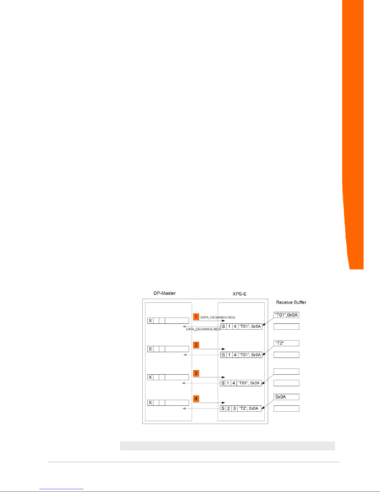
Illustration4: Empfang im Seriell getriggerten–Modus(Endezeichen:0x0A)
x= Receive request number S= Status
Data exchange
Page 18

XPS-E
18 / 36
NOTICE
Please note, that it is not necessary to set the receive request number (X)
in polling/serial Mode
1. The data_exchange.req is transmitted to the XPS-E. XPS-E has already
received data via the serial interface. This data are transmitted with
data_exchange.res back to the DP-Master. The receive confirmation
number is incremented and data length and status are updated.
¬
2. Next data_exchange.req service. XPS-E responds with the old data.
New data are in fact received, but they do not contain the trigger
character.
¬
3. Next data_exchange.req service. XPS-E responds with the old data,
because no further serial data were received.
¬
4. Next data_exchange.req service. XPS-E has received in the meantime
the serial trigger character. The receive confirmation number is
incremented, data length, status and data_exchange.res buffer are
updated with the actual data.
¬
Request-Mode
In the request mode the XPS-E only sends receive data if a modified
receive-request number is contained in the request telegram. The
data are not returned in the first response telegram but in the
response telegram of the subsequent data_exchange service. This
means that the data are returned always only in the subsequent
cycle of the request. If the response telegram contains received data,
the XPS-E confirmation number is incremented by one and returned
in the response telegram (as in the poll mode).
NOTICE
If this mode is used while the master is automatically polling the slaves
according to the poll list, the data that have been received last remain in the
process image
Data exchange
Page 19

XPS-E 19 / 36
Illustration5: Data Reception in Request Mode
S= Status
Data exchange
Page 20

XPS-E
20 / 36
1. The data_exchange.req telegram is sent to the XPS-E which already
has received the first characters. It returns them, however, only in the
subsequent response telegram data_exchange.res.
¬
2. New data_exchange.req telegram with increased receive-request
number (further reception command). XPS-E returns the data received
at point in time. The confirmation number is increased by one.
¬
3. Another reception command to XPS-E (receive-request number has
been increased). The data that are returned are the data received at
point in time.
¬
4. No further reception command to XPS-E. XPS-E returns again the last
sent data. XPS-E has already received new data.
¬
5. No further reception command to XPS-E. XPS-E returns again the last
sent data.
¬
6. This data_exchange.req contains another reception command. The
data are returned, however, only at the next cycle.
¬
7. No further reception command because the request number has not
been increased. The data that are returned are the data received until
the point in time of the last read command.
¬
Data exchange
Page 21

XPS-E 21 / 36
Modbus RTU Master
XPS-E works in Modbus RTU Mode as Modbus Master. Modbus
Slave is not supported. In Modbus RTU Mode the parameters Baud
Rate, Data Mode, XOFF/Modbus timeout, Async. hardware mode
and Baud Rate Multiplier apply. The parameter XOFF/Modbus
timeout is adjusted in multiples of 100 ms and determines the timeout
period for a non-responding Modbus Slave.
The configured PROFIBUS DP IO data sizes (see XPS-E GSD file)
limit the max. size of the Modbus request and response telegrams
exchanged with the PROFIBUS DP Master. The max. possible size
of a Modbus RTU telegram is 237 Bytes (240 Bytes – 3 Byte header
information).
Transmit of a Modbus RTU
request telegram
Byte Telegram Element Value Range (dec)
1 Reserved
2 Send request number
0 – 255 (See Chapter
„S
end Data" [}15] )
3 Data length N of the following user
data
0 – 237 (See
Chapter„Send Data“,
Section „Modbus RTU-
Master“)
4 Adress Modbus RTU Slave 0 – 255
5 Modbus RTU Command 0 – 255
6+n Modbus RTU Data 0 – 255
Table9: Structure of a Modbus RTU Request-Telegram
The telegram buffer consists of 3 byte header and successive
Modbus specific application data (from byte 4).
By the header bytes the transmitting of the request telegram is
controlled. The header bytes are not transmitted to the Modbus
Slave.
– Byte 1
Reserved
–
Byte 2
The transmitting of the Modbus request telegram is triggered by
changing the Send request number in Byte 2. The Modbus RTU request
telegram is automatically generated incl. CRC and transmitted to the
Modbus slave.
– Byte 3
Byte 3 must be set to the size of the Modbus specific application data
from byte 4
For the detailed structure of the specific Modbus request telegrams
please refer to the Modbus slave user documentation.
Data exchange
Page 22

XPS-E
22 / 36
Reception of a Modbus RTU
response telegram
After transmitting a Modbus RTU request telegram, XPS-E waits for
a response of the addressed Modbus slave. After the correct
reception of the response telegram it is forwarded without CRC to the
PROFIBUS DP Master. If no response is received within the
configured timeout (See Chapter„Send Data“ [}15], Section „Modbus
RTU-Master) XPS-E reports via the receive status byte a timeout
error to the PROFIBUS DP Master.
Byte Telegram Element Value Range (dec)
1 Receive status 0 – 255
2 Receive confirmation number of
XPS-E
0 – 255 (See Chapter„
Receive Data“ [}15])
3
Data size N of the following user data 0 – 237 (See Chapter
Receive Data“,[}15]
Section „Modbus RTU
Master“).
4..4+N Modbus Data 0 – 255
Table10: Structure of a Modbus RTU Response-Telegramm
The telegram buffer consists of 3 byte header and successive
Modbus specific application data (from byte 4).
– Byte 1:Receive status of the Modbus RTU response telegram (Bit set =
status active):
Bit Meaning
0 Reserved
1 Reserved
2 Paritiy error
3 Receive data available
4 Reserved
5 Modbus request too large (max. PROFIBUS Output size-3)
6 Modbus response too large (max. PROFIBUS Input size - 3)
7 Modbus Timeout
Table11: Receive status of a Response-Telegram
Data exchange
Page 23

XPS-E 23 / 36
Status Meaning
0x02: Timeout expired. The Modbus slave did not respond within the
configured timeout period
0x08: Modbus response telegram correctly received
0x20: Modbus request too large (> configured PROFIBUS Output
size-3)
0x40: Modbus response too large (> configured PROFIBUS Input
size-3)
Table12: Status Codes
– Byte 2:If a correct Modbus response telegram is received, the receive
confirmation number is incremented (+1).
– Byte 3:Stores the data size of the Modbus response telegram
Modbus ASCII Master
The transmit and reception of Modbus ASCII telegrams complies with
the mechanism for the Modbus RTU Master described in detail in
chapter „R [}15]eceive Data“, Section „Modbus RTU Master.
Every request telegram received from the PROFIBUS DP Master is
automatically extended by a colon (:) as well as the calculated LRC
and a CR LF string.
Received response telegrams are checked and forwarded without
colon (:), LRC and CR LF string to the PROFIBUS DP Master.
Data exchange
Page 24

XPS-E
24 / 36
4.3 Send and Receive Data
It is generally possible in both modes to send and receive data
simultaneously. The request telegrams described in the previous
chapters then have to be completed only by the entries of the
transmission command (transmission command number, length of
transmission data, data).
Please note that the data are only accepted and transmitted by the
XPS-E if the transmission command number in the
data_exchange.req telegram to the XPS-E has changed.
Illustration6: Combined Send- and Receive Request
Data exchange
Page 25

XPS-E 25 / 36
5 Status and Error Messages
5.1 External Device Diagnostics
External device diagnostics can be realised by means of the service
slave_diag Octet 8 of the response telegram contains the device
status and is encoded as follows:
Illustration7: Byte Definition of external Device Diagnostics
1 RS_PORT_CFG_ERROR
Invalid parameter at parametrization of serial interface.
2 Not significant
Status and Error Messages
Page 26

XPS-E
26 / 36
5.2 Communication Status
In the status of the confirmation telegram of the service
data_exchange the status of the serial interface is encoded as
follows:
Illustration8: Byte Definition of Communication Status
0 RS_PORT_TX_DATA
Data are being transmitted.
1 Modbus_TIMEOUT
2 RS_PORT_PARITY_ERROR
Parity error of receive data of serial interface.
3 RS_PORT_RX_DATA_AVAIL
XPS-E has data in receive buffer.
4 XOFF_CTS_
XOFF was received or CTS is inactive.
5 OUTPUT_DATA_LEN_FAILURE
user data length exceeds maximal data_exchange length minus 3 (on
part of PROFIBUS)
6 RS_PORT_RX_OVERFLOW
Receive buffer overflow
7 XOFF_TOMEOUT
No XON received after XOFF- Timeout. Sending process was restar-
ted.
Status and Error Messages
Page 27

XPS-E 27 / 36
6 Connector Assignment and Cabling
6.1 PROFIBUS
Connector Assignment
The PROFIBUS connection is executed according to EN50170 as 9pin female D-SUB with the following assignment:
Pin RS422
Ref.
Signal Function Direction
1 - - Shielding 2 - - NC 3 B/B´ RxD/TxD-P Data (+) I/O
4 - CNTR-P Control character (+) O
5 C/C´ DGND Data Ground 6 - VP Supply for Terminator (+5V) 7 - - NC 8 A/A´ RxD/TxD-N Data (-) I/O
9 - CNTR-N Control character l (-) O
Table13: Connector Assignment PROFIBUS
O = Output I= Input
PROFIBUS Terminating Resistor
For correct operation of XPS-E both bus terminations of the line
segment must be provided with a terminator. This terminator must
match with the impedance level of the line. Typically, in case of new
PROFIBUS installations, Type A will be used. The assignment of the
individual terminating resistors of the terminator is depicted in the
following figure.
Illustration9: Assignment of PROFIBUS Terminator Type A
Connector Assignment and Cabling
Page 28
XPS-E
28 / 36
Cabling
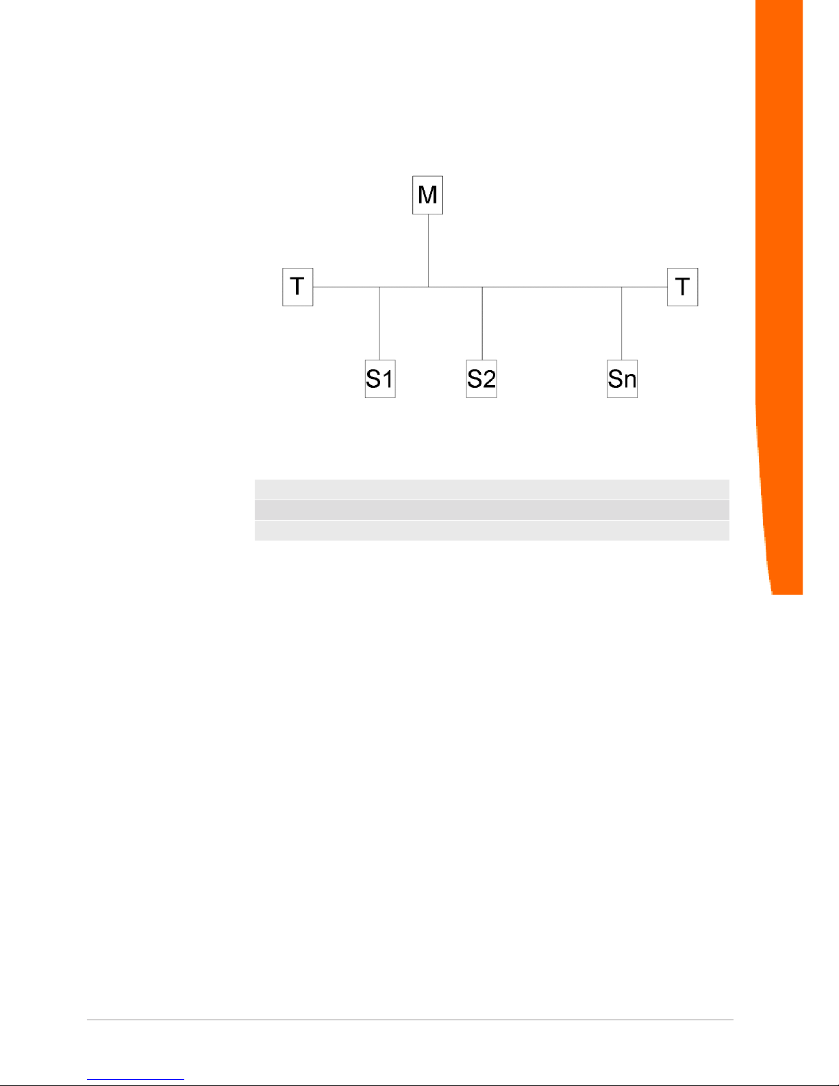
Illustration10: Connection of a PROFIBUS-DP Slave within a Segment
T= Terminator
M= Master
S= Slave n<31
If no terminator with independent power supply shall be used (active
terminator), the termination must be realised directly at the last
stations of the bus. This station must then supply the terminator with
power. For details regarding the PROFIBUS installation please refer
to the PROFIBUS Installation Guidelines of the PROFIBUS User
Organisation (PNO, Order No.: 2.112).
Connector Assignment and Cabling
Page 29

XPS-E 29 / 36
6.2 Serial Interface
Connector Assignment RS232
The connection is realised via a 9-pin D-SUB plug.
Pin Signal FNI CCITT Function Direction
1 DCD M5 109 Data Carrier Detect I
2 RxD D2 104 Receive Data I
3 TxD D1 103 Transmit Data O
4 DTR S1 108.2 Data Terminal Ready O
5 GND E2 102 Ground 6 DSR M1 107 Data Set Ready I
7 RTS S2 105 Request to Send O
8 CTS M2 106 Clear To Send I
9 - - - Not connected -
Table14: Pin Assignment RS232 Interface
O= Output I= Input
Cabling RS232
RS232-Cabling without
Hardware Handshake
Illustration11: RS232 Cabling without Hardware Handshake
Connector Assignment and Cabling
Page 30

XPS-E
30 / 36
RS232-Cabling with
Hardware Handshake
Illustration12: RS232 Cabling with Hardware Handshake
RS422 Interface
The connection is realised via a 9-pin D-SUB plug.
Pin Signal Function Direction
1 I(B) Indicate (-) I
2 R(A) Receive Data (+) I
3 T(A) Transmit Data (+) O
4 T(B) Transmit Data (-) O
5 G Ground 6 R(B) Receive data (-) I
7 C(A) Control (+) O
8 I(A) Indicate (+) I
9 C(B) Control (-) O
Table15: Pin Assignment RS422 Interface
O = Output I= Input
Connector Assignment and Cabling
Page 31

XPS-E 31 / 36
RS422 Cabling without
Hardware Handshake
Illustration13: RS422 Cabling without Hardware Handshake
RS422 Cabling with
Hardware Handshake
Illustration14: RS422 Cabling with Hardware Handshake
Connector Assignment and Cabling
Page 32

XPS-E
32 / 36
7 FAQ
This section is treating the most frequent application problems and
their solutions.The most current questions and answers can be found
under
http://www.kunbus.de
DP-Master Status Message: Status 0xC2 (SAP/Service not
activated)
Make sure that the parametrization sequence of the parametrization
described in chapter „Parametrization“ [}9] has correctly been
executed. If necessary, repeat parametrization.
DP-Master Status Message: Status 0xC3 (no acknowledge)
Check the following points:
– Does the station address of the XPS-E correspond to the setting of the
PROFIBUS Master device?
– Are the bus parameters set correctly?
– Is the bus terminated correctly (switch position of the terminator
integrated in XPS-E)?
– Has XPS-E been connected correctly?
DP-Master Status Message: Status 0xC4 (bad telegram)
Check the terminating resistors at the bus. Pay attention to the switch
position of the terminating resistor at the XPS-E.
FAQ
Page 33

XPS-E 33 / 36
8 Technical Data
PROFIBUS-DP-Interface
Transmission protocol PROFIBUS-DP acc. to EN50170-3
Slave coupler
Transmission rates 9.6Kbit/s, 19.2Kbit/s, 93.75Kbit/s, 187.5Kbit/s,
500Kbit/s, 1.5Mbit/s, 3Mbit/s, 6Mbit/s, 12Mbit/s,
automatic adjustment
Potential segregation: Opto-coupler interface and DC/DC transducer
Isolation voltage U>500V
Terminator TYP A
Operating modes Sync_Req and Freeze_Req are not supported.
Addressing 1 - 99 Sync_Req and Freeze_Req are not sup-
ported.
Ident-Number 0x9510
Parametrization data: 23 Byte ( 16 Byte User Parameter)
Diagnostic information 6 Byte system diagnostics acc. to standard
8 Byte device-specific diagnostics
Data_Exchange Buffer 4 - 240 Byte I/O selectable (3 Bytes with
header functionality).
RS232-Interface
Interface RS232 interface with Handshake signals (RTS,
CTS).
RS422/485 interface with Handshake signals
(CONTROL, INDICATION).
Interface physics can be adjusted via
PROFIBUS by means of User_Parameter.
Transmission rates 150bit/s, 300bit/s, 600bit/s, 1.200bit/s, 2.400bit/
s,4.800bit/s, 9.600bit/s, 19.200bit/s
Character Transmission 8N1, 7N2, 7E1, 7O1
Handshake HW (RTS/CTS, CONTROL/INDICATION),
SW(XON/XOFF), no
XOFF Timeout adjustable to max. 25,5 seconds
Data transmission modes Poll mode, Request mode, serial triggered
mode
Receive buffer 2 KByte
Potential segregation optional
Connection
Power Supply 2-pin spring clip 2,5mm
2 without ferrule 1,5mm
2 with ferrule
PROFIBUS-DP 9-pin female D-SUB (DIN 41652)
RS-Port 9-pin male D-SUB (DIN 41652)
Technical Data
Page 34

XPS-E
34 / 36
Operating Indicators and Controls
PROFIBUS Status LED “green” means RUN
“red” means BUSFAIL
RS-PORT Status LED RxD “red” corresponds to: data will be re-
ceived
TxD “red“ corresponds to: data will be sent
Hardware physics “red” corresponds to:
RS232 mode
PROFIBUS address window at coding switch
Technical Data
Case synthetic profile with aluminium front panel,
lacquered
Dimensions 126mm x 90mm x 38mm (LxWxH)
Weight 190g
Voltage range 18 – 30VDC
Power assumption 100mA (24VDC)
Storage temperature -25C .. +70C
Operation temperature 0C .. +55C non condensing
Protection class 1
Protection kind IP52
Standards CE, EN60950, EN50081-2, EN50082-2
Technical Data
Page 35

XPS-E 35 / 36
List of Figures
Illustration 1 Typical Connection................................................................................................... 6
Illustration 2 Connectors and Interfaces of the XPS-E ................................................................. 7
Illustration 3 Data Reception in Poll Mode.................................................................................... 16
Illustration 4 Empfang im Seriell getriggerten–Modus(Endezeichen:0x0A).................................. 17
Illustration 5 Data Reception in Request Mode ............................................................................ 19
Illustration 6 Combined Send- and Receive Request................................................................... 24
Illustration 7 Byte Definition of external Device Diagnostics......................................................... 25
Illustration 8 Byte Definition of Communication Status................................................................. 26
Illustration 9 Assignment of PROFIBUS Terminator Type A ........................................................ 27
Illustration 10 Connection of a PROFIBUS-DP Slave within a Segment ........................................ 28
Illustration 11 RS232 Cabling without Hardware Handshake ......................................................... 29
Illustration 12 RS232 Cabling with Hardware Handshake .............................................................. 30
Illustration 13 RS422 Cabling without Hardware Handshake ......................................................... 31
Illustration 14 RS422 Cabling with Hardware Handshake .............................................................. 31
List of Figures
Page 36

XPS-E
36 / 36
List of Tables
Table 1 set_prm .......................................................................................................................... 10
Table 2 slave_diag ...................................................................................................................... 11
Table 3 Baud Rate of Serial Interface Oktet 12 .......................................................................... 12
Table 4 Character Transmisson Mode Oktet 13 ......................................................................... 13
Table 5 Handshake-Modi Oktet 14 ............................................................................................. 13
Table 6 Data Transmission Mode Oktet 16 ................................................................................ 14
Table 7 Extended configuration byte Oktet 17............................................................................ 14
Table 8 Trigger character Oktet 18 ............................................................................................. 14
Table 9 Structure of a Modbus RTU Request-Telegram ............................................................ 21
Table 10 Structure of a Modbus RTU Response-Telegramm....................................................... 22
Table 11 Receive status of a Response-Telegram....................................................................... 22
Table 12 Status Codes ................................................................................................................. 23
Table 13 Connector Assignment PROFIBUS ............................................................................... 27
Table 14 Pin Assignment RS232 Interface ................................................................................... 29
Table 15 Pin Assignment RS422 Interface ................................................................................... 30
List of Tables
 Loading...