

Page 1

User Manual
Gateway component for DeviceNet
PR100071 • 1/7/2016
TM
Page 2

Table of Contents KUNBUS GmbH
Table of Contents
1 General Information ........................................................................................................................3
1.1 Disclaimer..................................................................................................................................3
1.2 Notes Regarding this User Manual............................................................................................4
1.3 Validity .......................................................................................................................................4
1.4 Limitation of Liability ..................................................................................................................4
1.5 Customer Service ......................................................................................................................4
2 Safe Use ...........................................................................................................................................5
2.1 User ...........................................................................................................................................5
2.2 Symbols.....................................................................................................................................5
3 Overview ..........................................................................................................................................6
3.1 Functionality ..............................................................................................................................6
3.2 Control Elements .......................................................................................................................7
3.3 Status LEDs.............................................................................................................................10
4 Installation .....................................................................................................................................12
4.1 Preparations for Trouble-free Operation..................................................................................12
4.2 Requirements .........................................................................................................................14
4.3 Connecting Gateway Components..........................................................................................15
4.4 Installing a Gateway in the Control Cabinet ............................................................................16
4.5 Connecting a Power Supply ....................................................................................................17
4.6 Connecting a Gateway to the Fieldbus....................................................................................18
5 Configuration.................................................................................................................................19
5.1 Supported Size of the Process Data ......................................................................................19
5.2 Setting MAC-ID and bitrate......................................................................................................19
5.3 DeviceNet Objects...................................................................................................................20
6 Technical Data...............................................................................................................................37
6.1 Technical Data.........................................................................................................................37
ii Gateway component for DeviceNetTM
Page 3

1 General Information
1.1 Disclaimer
© 2015 KUNBUS GmbH, Denkendorf (Germany)
The contents of this user manual have been prepared by KUNBUS
GmbH with the utmost care. Due to technical development, KUNBUS
GmbH reserves the right to change or replace the contents of this
user manual without prior notice. You can always obtain the latest
version of the user manual at our homepage: www.kunbus.de
KUNBUS GmbH shall be liable exclusively to the extent specified in
General Terms and Conditions (www.kunbus.de/agb.html).
The contents published in this user manual are protected by
copyright. Any reproduction or use for the in-house requirements of
the user is permitted. Reproduction or use for other purposes is not
permitted without the express, written consent of KUNBUS GmbH.
Contraventions shall result in compensation for damages.
General Information
Trademark protection
– KUNBUS is a registered trademark of KUNBUS GmbH
– Windows® and Microsoft® are registered trademarks of Microsoft Corp.
KUNBUS GmbH
Heerweg 15 c
73770 Denkendorf
Germany
www.kunbus.de
Gateway component for DeviceNetTM 3 / 38
Page 4

1.2 Notes Regarding this User Manual
This user manual provides important technical information that can
enable you as a user to integrate the Gateways into your applications
and systems efficiently, safely and conveniently. It is intended for
trained, qualified personnel, whose sound knowledge in the field of
electronic circuits and expertise in DeviceNetTM is assumed.
As an integral part of the module, the information provided here
should be kept and made available to the user.
1.3 Validity
This document describes the application of the KUNBUS Gateway
with the product number:
– PR100071, release 00
1.4 Limitation of Liability
Warranty and liability claims will lapse if:
General Information
– the product has been used incorrectly,
– damage is due to non-observance of the operating manual,
– damage is caused by inadequately qualified personnel,
– damage is caused by technical modification to the product (e.g.
soldering).
1.5 Customer Service
If you have any questions or suggestions concerning this product,
please do not hesitate to contact us:
KUNBUS GmbH
Heerweg 15 C
73770 Denkendorf
+49 (0)711 3409 7077
[email protected]
www.kunbus.de
Gateway component for DeviceNetTM
4 / 38
Page 5

2 Safe Use
2.1 User
The Gateway may only be assembled, installed and put into
operation by trained, qualified personnel. Before assembly, it is
absolutely essential that this documentation has been read carefully
and understood. Expertise in the following fields is assumed:
– electronic circuits,
– basic knowledge of DeviceNet,
– work in electrostatic protected areas,
– locally applicable rules and regulations for occupational safety.
2.2 Symbols
The symbols used have the following meaning:
Safe Use
DANGER
CAUTION
NOTICE
Danger
Always observe this information!
There is a safety hazard that can lead to serious injuries and death.
Caution
There is a safety hazard that can result in minor injuries and material
damage.
Note
There is a safety hazard that can result in material damage.
Gateway component for DeviceNetTM 5 / 38
Page 6

3 Overview
3.1 Functionality
The KUNBUS Gateway is a protocol converter. It allows
communication between networks with different protocols.
Overview
Illustration1: Functionality
A Gateway consists of 2 gateway components that master one
specific protocol each. You can combine these gateway components
as you wish. This design offers you a high degree of flexibility, since
you can exchange the individual gateway components at any time.
The following gateway components are currently available as slaves:
– CANopen
– CC-Link
– DeviceNet
– EtherCAT
– EtherNet/IP
– Modbus RTU
– Modbus TCP
– POWERLINK
– PROFIBUS
– PROFINET
– Sercos III
Gateway component for DeviceNetTM
6 / 38
Page 7

3.2 Control Elements
1
2
3
Front view
Overview
Illustration2: Front view DeviceNet
1 Status LEDs
2 DIP Switches
3 Fieldbus connection
Gateway component for DeviceNetTM 7 / 38
Page 8

Top
1
1
2
Overview
Illustration3: Top
1 Interconnect ports
for interconnecting the gateway components.
2 Locking clamps
for securely attaching the gateway component to the DIN rail.
Gateway component for DeviceNetTM
8 / 38
Page 9

Bottom
1
2
Overview
Illustration4: Bottom
1 Mains connection
with 24 V power supply
2 Locking clamps
for securely attaching the gateway component to the DIN rail.
Gateway component for DeviceNetTM 9 / 38
Page 10

3.3 Status LEDs
The signals of the status LEDs for DeviceNet have the following
meaning:
Overview
LED
designation
Power off Gateway not running
NS off Device is offline
Signal Meaning
blinks, green Initialization phase not yet completed
on, green All system components are functioning
perfectly
flashes, red Correctable error (e.g. second gateway
component missing)
on, red Serious error/defect in the gateway
Possible causes:
– The Dup_MAC_ID-Test has not yet been
completed
– No voltage present (s. module status LED)
No network connection
blinks, green Online, no connection was established
green Connection established
flashes, red At least one I/0 connection is in timeout
state.
red Critical error
An error has occurred preventing the
connection to the network (e.g. dupli-
cate MAC ID, fieldbus is offline).
flashes red and
green
Communication error
A network access error was detected.
Gateway component for DeviceNetTM
10 / 38
Page 11

LED
designation
MS off The gateway component is not in oper-
Signal Meaning
ation. Check the power supply.
green, flashes Start-up
At least one system component has not
yet finished its initialization. This also
includes the automatic bitrate detec-
tion.
green, on Normal operation
All system components are running
perfectly. The partner gateway compo-
nent is connected correctly.
red, flashes At least one system component is not
running due to a configuration error or
the partner gateway component is not
connected.
red, on Internal system error
A fatal internal system error has oc-
curred. Please contact our support.
flashes green
and red
Self-test
Overview
Gateway component for DeviceNetTM 11 / 38
Page 12

4 Installation
4.1 Preparations for Trouble-free Operation
In the following section we have compiled some general information
for you that is important for trouble-free operation. If you are already
acquainted with this topic, you can skip to the next section. There,
you will learn about which conditions are necessary for installing the
gateway.
Cable routing
Route your cables separately in cable groups. This will protect your
gateway from any unintended electromagnetic interferences.
The following groups should be routed separately from each other:
Group Line
A Data and power supply lines for:
DC voltage below 60V
AC voltage below 25V
B Data and power supply lines for:
DC voltage between 60V and 400V
AC voltage between 25 and 400V
C Power supply lines above 400V
Installation
– You can route cables of the same group together in cable ducts or
bundles.
– Cables of group A and B:
– Route the groups in separate bundles or
– in cable ducts at a minimum distance of 10 cm from each other.
– Cables of group C
– Route the groups in separate bundles or
– in cable ducts at a minimum distance of 50 cm from the other
groups.
Gateway component for DeviceNetTM
12 / 38
Page 13

Shielding
Shield your cables. This will reduce any unintended electromagnetic
interferences.
Potential equalization
Potential differences occur when devices are connected to different
earths. These potential differences cause malfunctions.
To prevent malfunctions, you have to route an equipotential
equalization conductor.
When doing so, bear in mind the following points:
– Select an equipotential equalization conductor with low impedance.
– Select the following as a reference value for the cross-section of the
potential equalization cable:
– 16 mm2 for potential equalization cables of up to 200 m in length
– 25 mm2 for potential equalization cables of more than 200 m in
length
– Use potential equalization cables made of copper or galvanized steel.
– Connect potential equalization cables extensively with the earth rail.
– The smallest surfaces possible should be sandwiched between
potential equalization cables and signal cables.
Installation
If the devices of the control system are connected by shielded signal
cables that are earthed on both sides, the impedance must be 10%
of the shielding impedance.
Gateway component for DeviceNetTM 13 / 38
Page 14
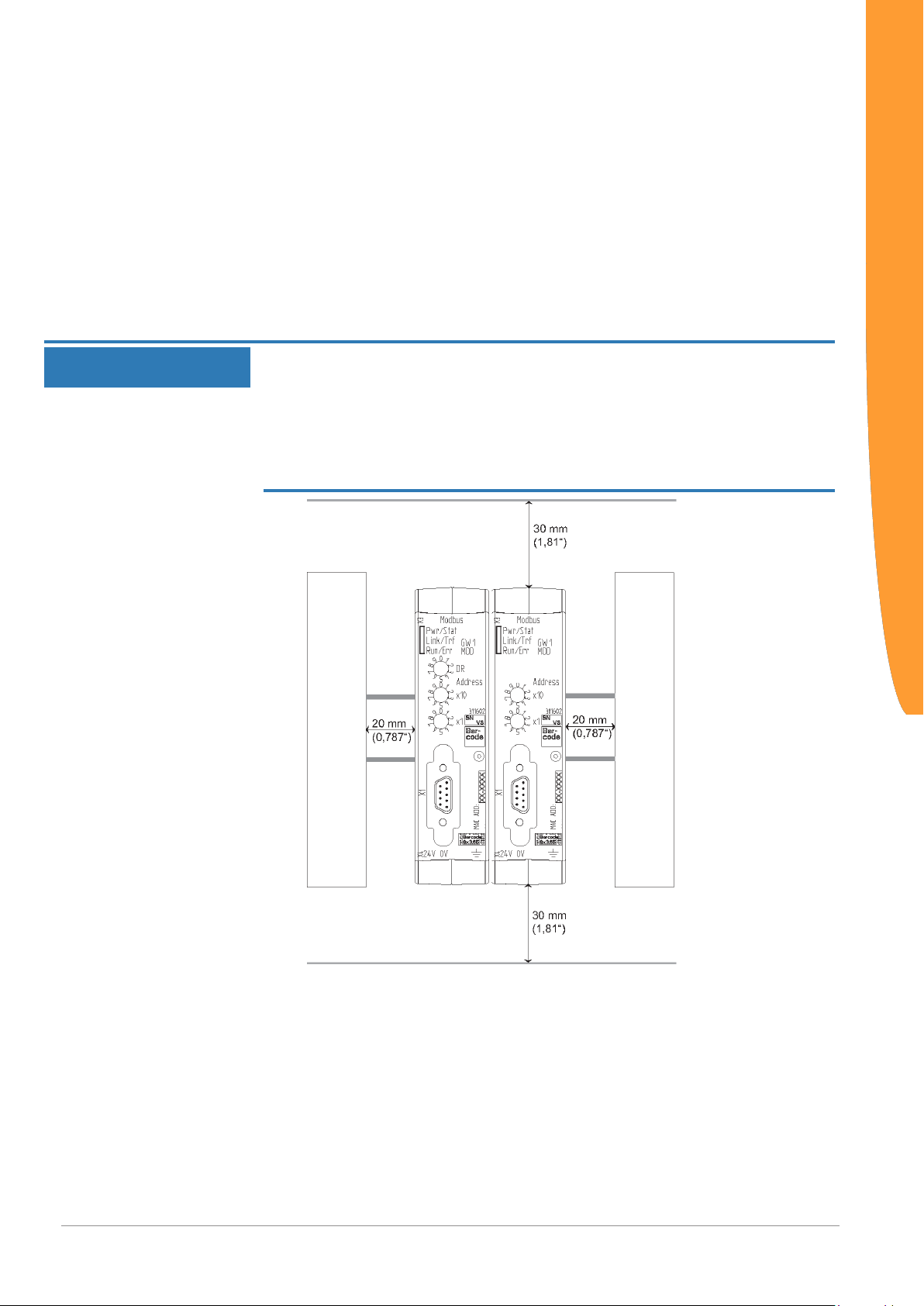
4.2 Requirements
The Gateway was designed for use in a control cabinet.
NOTICE
ü The protection class of the control cabinet must be equivalent to at least
IP54.
ü For installation in the control cabinet you need a DIN rail 35 x 7.5mm
(EN50022).
◦ Install the DIN rail horizontally in the control cabinet according to the
manufacturers' specifications. When doing so, make sure that the
Gateway is at a sufficient distance from other devices.
Your gateway could be damaged if temperatures are too high.
èMake sure that the ambient temperature in the control cabinet is less
than 60°C.
èKeep the ventilation slots unobstructed. These must not be covered by
cables etc.
èMaintain sufficient distance from other devices.
Installation
Illustration5: Distances for installation
◦ Connect each gateway component individually to functional earth.
ð Your control cabinet now meets all requirements for installing the
Gateway component for DeviceNetTM
When doing so, make sure that the power supplies of both gateway
components have the same ground.
gateway.
14 / 38
Page 15
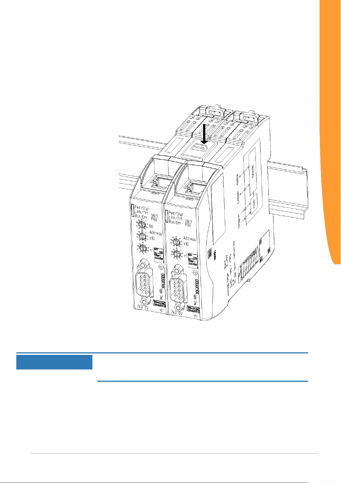
4.3 Connecting Gateway Components
In order to attain a fully functional gateway, you have to interconnect
both gateway components.
◦ Connect an interconnect port to each gateway component using the
plug-in jumper (product number PR100204).
◦
Installation
Illustration6: Connecting gateway components
ð You can now install the gateway in the control cabinet.
Only ever interconnect 2 gateway components.
NOTICE
If you connect additional components, severe defects could result on all
devices.
Gateway component for DeviceNetTM 15 / 38
Page 16
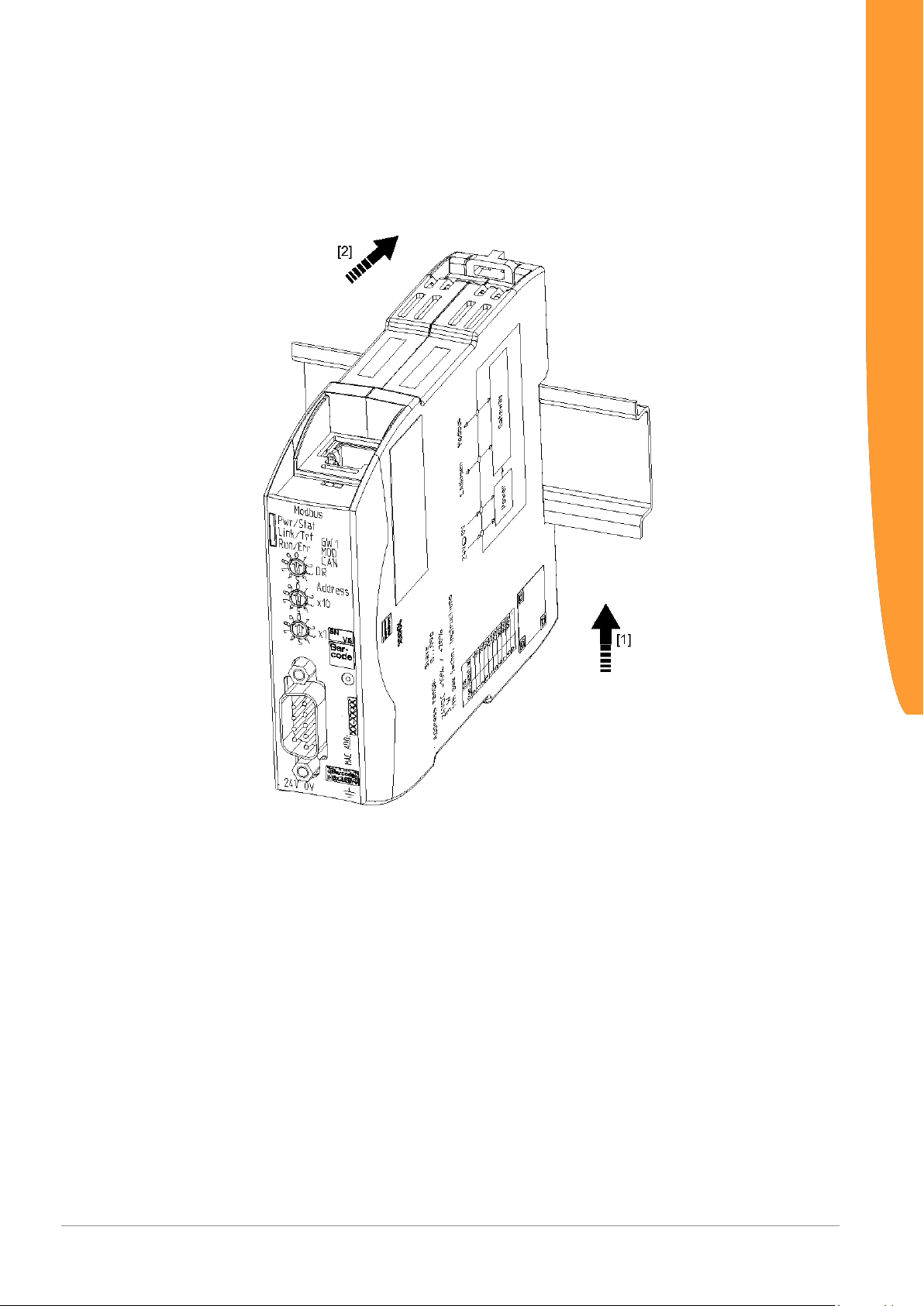
4.4 Installing a Gateway in the Control Cabinet
◦ Hold the raster element of the gateway on the DIN rail.
◦ Press down the locking elements towards the gateway.
◦ Make sure that the gateway is firmly attached to the DIN rail.
Installation
Gateway component for DeviceNetTM
16 / 38
Page 17
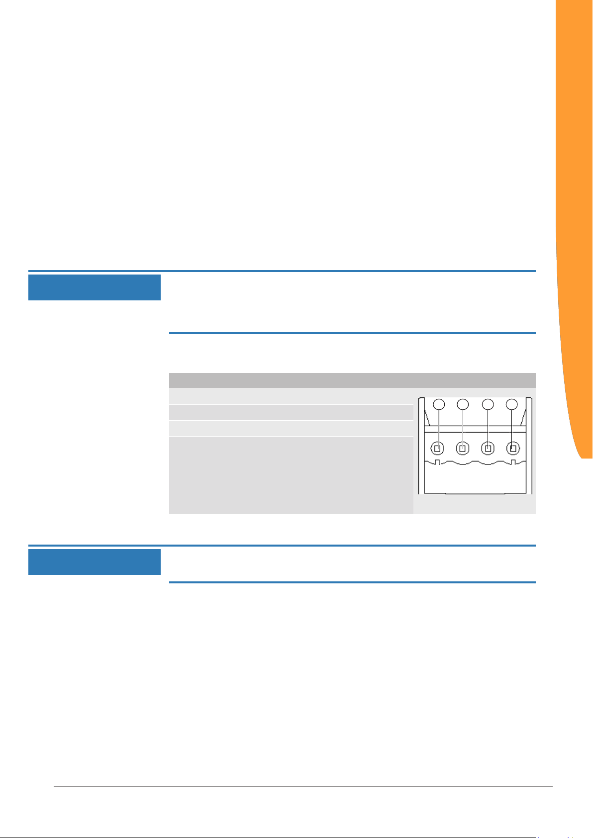
4.5 Connecting a Power Supply
3
1
2
4
To connect the gateway component to the power supply, you need a
spring-loaded terminal (e.g. Metz-Connect SP995xxVBNC).
You have to connect each gateway component separately to a power
supply. Never interconnect functional earth and GND, otherwise the
galvanic isolation between gateway GND and fieldbus ground will be
removed. Instead, connect the functional earth with low impedance to
the potential equalization. You can then dispense with this
connection if the shield of the fieldbus cable is connected to the
potential equalization with lower impedance when entering the
control cabinet.
Installation
NOTICE
NOTICE
Connect each of the two gateway components to its own power
supply
èEnsure in particular that no potential differences occur between the
GND pins (2).
Pin assignment:
Pin Assignment
1 24V for module supply
2 GND
3 Do not connect!
4 Functional earth
Do not connect GND to PE
This connection could cause unintended malfunctions.
Gateway component for DeviceNetTM 17 / 38
Page 18

4.6 Connecting a Gateway to the Fieldbus
To connect the gateway component to DeviceNet, you need One 5pin Combicon connector.
The pin assignment complies with the specifications of the ODVA.
Cable color Signal
White CAN_H
Blue CAN_L
Not isolated drain
Black VRed V+
Installation
Gateway component for DeviceNetTM
18 / 38
Page 19
5 Configuration
5.1 Supported Size of the Process Data
NOTICE
The gateway component for DeviceNet supports process data of a
length up to 64 bytes.
An additional 448 bytes are available for the asynchronous data
traffic.
Bear in mind that the maximum length of the process data is always
determined by the fieldbus with the shorter data length.
5.2 Setting MAC-ID and bitrate
The MAC-ID and bitrate are assigned in binary format.
You can set the MAC ID via the DIP switches 1-32, and via switches
S1 and S2 you can set the bitrate.
Set an address switch to "OFF" to switch bit value 0 or to "ON" to
switch bit value 1.
Valid value range for the bitrate:
Valid value range for the MAC-ID: 0-63
Configuration
Example: Here, you can see the switch setting for the MAC address
42 and the bitrate 500 kBit/s.
Designation S2 S1 32 16 8 4 2 1
Switch setting on off on off on off on off
Gateway component for DeviceNetTM 19 / 38
Page 20

5.3 DeviceNet Objects
To configure the gateway component, you have to make the
appropriate settings in the DeviceNet objects with the configuration
software of your Device master.
Object structure
DeviceNetTM uses the application layer CIPTM (Common Industrial
Protocol) that was specified by the ODVA (Open DeviceNet Vendor
Association - http://www.odva.org). Physically based DeviceNet on
CAN (Controller Area Network).
CIP is a connection oriented protocol. It allows the exchange of I/O
data via cyclical I/O messages and the exchange of general data for
configuration, diagnosis and Management via explicit messages. For
this purpose, CIP defines 4 essential functions:
– Uniform object model for addressing data
– Uniform communication model for exchanging data
– Uniform configuration methods
– Uniform device profiles
Configuration
Each DeviceNet device is characterized by a collection of objects.
Each object has a defined behavior. Each object belongs to a class.
Objects belonging to the same class are called instances of this
class. Data elements within an object are called attributes. All
attributes can be addressed with class, instance and attribute IDs.
Services are explicit tasks that an object can execute.
The following sections describe which objects, attributes and
services are supported by the gateway component.
Gateway component for DeviceNetTM
20 / 38
Page 21

Class Code 0x01Hex
This class contains information about the identification of the module.
The gateway component supports the following functions in this
class:
– Get Attribute Single (0x0e): This function returns the content of certain
attributes.
– Reset Service (0x05)
– Type 0: The module restarts the DeviceNet software.
– Type 1: The module is reset to the original settings.
The Gateway supports the following services in the instances:
Configuration
Instance 0
Instance 1
# Name Access Type Value
1 Revision Get UINT 0x1
# Name Access Type Description
1 Vendor ID Get UINT 1168 (KUNBUS GmbH
Industrial Communication)
2 Device Type Get UINT 0x00c
3 Product Code Get UINT 0x0049 (73)
4 Revision Get STRUCTof: Version number
Major USINT Main version
Minor USINT Sub-version number
5 Status Get WORD s. Table Device Status
6 Serial number Get UDINT Assigned by KUNBUS dur-
ing the production process.
7 Product Name Get SHORT_
STRING
KUNBUS-mGate DeviceNet
Gateway component for DeviceNetTM 21 / 38
Page 22

Bit(s) Name
0 These is a connection to the master/scanner
1 Reserved (set to 0)
2 Configured (always set to 0)
3 Reserved (set to 0)
4-7
0000b
0010b
0011b
0100b
0110b
0111b
Others
8 A recoverable error has occurred
9 An unrecoverable error has occurred
10 A serious recoverable error has occurred
11 A serious unrecoverable error has occurred
12-15 Reserved (set to 0)
Extended Device Status
Unknown
Timeout
No IO connection established
Not implemented
Connection in Run mode
Connection in idle mode
Reserved
Configuration
Table1: Device Status
Class Code 0x02 Hex
This class represents a communication connecting point. This allows
a service to be triggered in any class or instance.
Gateway component for DeviceNetTM
22 / 38
Page 23

Class Code 0x03 Hex
In this class you will find information about the configuration and
status of a DeviceNet port.
The gateway component supports the following functions in this
class:
Class Services
– Get Attribute Single (0x0e)
Instance Services
– Get Attribute Single (0x0e)
– Set Attribute Single (0x10)
– Allocate Master/Slave Connection Set (0x4b)
– Release Master/Slave Connection Set (0x4c)
The gateway component supports the following data in this class:
Configuration
Instance 0
Instance 1
# Name Access Type Value
1 Revision Get UINT 0x2
# Name Access Type Description
1 MAC ID Get USINT Value range 0–63.
Default value: 63
You can set the MAC-ID on
the DIP switches.
2 Bitrate Get USINT Value Range
– 0: 125 kBit/s
– 1: 250 kBit/s
– 2: 500 kBit/s
– 3: Automatic bitrate detection
Default value: 125 kBit/s
You can set the bitrate on the
DIP switches.
3 BOI Get/Set BOOL Bus–Off Interrupt
4 Bus–Off
Counter
5 Allocation In-
formation
Allocation
Choice Byte
Get/Set USINT This value indicates how often
the module changes to the Off
state.
Value range 0–255
Get STRUCT
of:
BYTE
You can find further informa-
tion in the DeviceNet specifi-
cations volume 3, in section
5.11.
Gateway component for DeviceNetTM 23 / 38
Page 24

Master’s MAC
ID
6 MAC ID Switch
Changed
7 Bit Rate Switch
Changed
8 MAC ID Switch
Value
9 Bit Rate Switch
Value
10 Quick_Connect Get/Set BOOL Activates or deactivates Quick
Get BOOL This value indicates whether
Get BOOL This value indicates whether
Get USINT Current values of the switches
Get USINT Current values of the switches
USINT Value range 0–63, 255 MAC
ID from the master Change is
only possible by allocation
from the master.
the node ID has been
changed since the last restart.
0 = No change
1 = Change since the last start
the bitrate has been changed
since the last restart.
0 = No change
1 = Change since the last start
for the node ID
Value range 0-99
for the bitrate.
Value range 0–9
Connect.
0 = Deactivated
1 =Activated
Configuration
Gateway component for DeviceNetTM
24 / 38
Page 25

Class Code 0x04 Hex
This object enables you to access the input and output data.
The gateway component supports the following functions in this
class:
Class Services
– Get Attribute Single (0x0e)
Instance Services
– Get Attribute Single (0x0e)
– Set Attribute Single (0x10)
The gateway component supports the following data in this class:
Configuration
Instance 0
Instance 0x64
Instance 0x96
# Name Access Type Value
1 Version Get UINT 0x0001
# Name Access Type Value
3 Data Get Array of
BYTE
4 Length Get UNIT Length of the input and out-
# Name Access Type Value
3 Data Get/Set Array of
BYTE
Enables access to the input
data area
put data area
Enables access to the output
data area
Gateway component for DeviceNetTM 25 / 38
Page 26
Class Code 0x05 Hex
The gateway component supports the following functions in this
class:
Class Services
– Get Attribute Single (0x0e)
Instance Services
– Get Attribute Single (0x0e)
– Set Attribute Single (0x10)
The gateway component supports the following data in this class:
Configuration
Instance 0
# Name Access Type Value
1 Version Get UINT 0x0002
Gateway component for DeviceNetTM
26 / 38
Page 27

Instance 1
# Name Access Type Description
1 State Get USINT State of the object
3: Established
5: Delete latent objects
2 Instance type Get USINT Indicates whether it is an
I/O connection or explicit
connection.
3 Transport-
Class
trigger
4 DeviceNet
produced
connection id
5 DeviceNet
consumed
connection id
6 DeviceNet
initial comm
characteristics
7 Produced
connection
size
8 Consumed
connection
size
9 Expected
packet rate
12 Watchdog
timeout action
13 Produced
connection
path length
14 Produced
connection
path
15 Consumed
connection
path length
16 Consumed
connection
path
Get BYTE Defines the behavior of the
connection
Get UINT Positioned in CAN identifier
field if data is transmitted via
the existing connection in a
DeviceNet- Subnet.
Get UINT Value is in the CAN Identifier
field. It signals that messages can be received.
Get BYTE Defines the message group
of this connection based on
production and consumption.
Get UINT Maximum number of bytes
that were transmitted via this
connection
Get UINT Maximum number of bytes
that were received via this
connection
Get/Set UINT Defines the timing of the cur-
rent connection
Get/Set USINT Controls the behavior during
inactivity and Watchdog
Timeouts
UINT Number of bytes of the at-
tribute "Produced_connection_path"
Packed
EPATH
UINT Number of bytes of the at-
Packed
EPATH
Displays the application object(s) whose data was produced in the current connection.
tribute "Consumed_connection_path"
Displays the application object(s) whose data was used
in the current connection.
Configuration
Gateway component for DeviceNetTM 27 / 38
Page 28

Instance 2
# Name Access Type Description
1 State Get USINT State of the object
3: Established
5: Delete latent objects
2 Instance type Get USINT Indicates whether it is an I/O
connection or explicit
connection.
3 Transport-
Class trigger
4 DeviceNet
produced
connection id
5 DeviceNet
consumed
connection id
6 DeviceNet
initial comm
characteristics
7 Produced
connection
size
8 Consumed
connection
size
9 Expected
packet rate
12 Watchdog
timeout action
13 Produced
connection
path length
14 Produced
connection
path
15 Consumed
connection
path length
16 Consumed
connection
path
Get BYTE Defines the behavior of the
connection
Get UINT Positioned in CAN identifier
field if data is transmitted via
the existing connection in a
DeviceNet- Subnet.
Get UINT Value is in the CAN Identifier
field. It signals that messages can be received.
Get BYTE Defines the message group
of this connection based on
consumption and production.
Get UINT Maximum number of bytes
that were transmitted via this
connection
Get UINT Maximum number of bytes
that were received via this
connection
Get/Set UINT Defines the timing of the cur-
rent connection
Get/Set USINT Controls the behavior during
inactivity and Watchdog
Timeouts
UINT Number of bytes of the at-
tribute "Produced_connection_path"
Packed
EPATH
UINT Number of bytes of the at-
Packed
EPATH
Displays the application object(s) whose data was produced in the current connection.
tribute "Consumed_connection_path"
Displays the application object(s) whose data was used
in the current connection.
Configuration
Gateway component for DeviceNetTM
28 / 38
Page 29

Instance 3
# Name Access Type Description
1 State Get USINT State of the object
3: Established
5: Delete latent objects
2 Instance type Get USINT Indicates whether it is an I/O
connection or explicit
connection.
3 Transport-
Class trigger
4 DeviceNet
produced
connection id
5 DeviceNet
consumed
connection id
6 DeviceNet ini-
tial comm
characteristics
7 Produced
connection
size
8 Consumed
connection
size
9 Expected
packet rate
12 Watchdog
timeout action
13 Produced
connection
path length
14 Produced
connection
path
15 Consumed
connection
path length
16 Consumed
connection
path
Get BYTE Defines the behavior of the
connection
Get UINT Positioned in CAN identifier
field if data is transmitted via
the existing connection in a
DeviceNet- Subnet.
Get UINT Value is in the CAN Identifier
field. It signals that messages can be received.
Get BYTE Defines the message group
of this connection based on
consumption and production.
Get UINT Maximum number of bytes
that were transmitted via this
connection
Get UINT Maximum number of bytes
that were received via this
connection
Get/Set UINT Defines the timing of the cur-
rent connection
Get/Set USINT Controls the behavior during
inactivity and Watchdog
Timeouts
UINT Number of bytes of the at-
tribute "Produced_connection_path"
Packed
EPATH
UINT Number of bytes of the at-
Packed
EPATH
Displays the application object(s) whose data was produced in the current connection.
tribute "Consumed_connection_path"
Displays the application object(s) whose data was used
in the current connection.
Configuration
Gateway component for DeviceNetTM 29 / 38
Page 30

Instance 4
# Name Access Type Description
1 State Get USINT State of the object
3: Established
5: Delete latent objects
2 Instance type Get USINT Indicates whether it is an
I/O connection or explicit
connection.
3 Transport-
Class trigger
4 DeviceNet
produced
connection id
5 DeviceNet
consumed
connection id
6 DeviceNet
initial comm
characteristics
7 Produced
connection
size
8 Consumed
connection
size
9 Expected
packet rate
12 Watchdog
timeout action
13 Produced
connection
path length
14 Produced
connection
path
15 Consumed
connection
path length
16 Consumed
connection
path
Get BYTE Defines the behavior of the
connection
Get UINT Positioned in CAN identifier
field if data is transmitted via
the existing connection in a
DeviceNet- Subnet.
Get UINT Value is in the CAN Identifier
field. It signals that messages can be received.
Get BYTE Defines the message group
of this connection based on
consumption and production.
Get UINT Maximum number of bytes
that were transmitted via this
connection
Get UINT Maximum number of bytes
that were received via this
connection
Get/Set UINT Defines the timing of the cur-
rent connection
Get/Set USINT Controls the behavior during
inactivity and Watchdog
Timeouts
UINT Number of bytes of the
attribute "Produced_connection_path"
Packed
EPATH
UINT Number of bytes of the at-
Packed
EPATH
Displays the application object(s) whose data was produced in the current connection.
tribute "Consumed_connection_path"
Displays the application object(s) whose data was used
in the current connection.
Configuration
Gateway component for DeviceNetTM
30 / 38
Page 31

17 Production
inhibit time
UINT Defines the minimum time
between the data productions.
This attribute is necessary
for all I/O client connections.
Excluded from this are connections with cyclical production triggers.
Configuration
Instance 10…12
# Name Access Type Description
1 State Get USINT State of the object
3: Established
5: Delete latent objects
2 Instance type Get USINT Indicates whether it is an I/
O connection or explicit
connection.
3 Transport-
Class trigger
4 DeviceNet
produced
connection id
5 DeviceNet
consumed
connection id
6 DeviceNet
initial comm
characteristics
7 Produced
connection
size
8 Consumed
connection
size
9 Expected
packet rate
12 Watchdog
timeout action
Get BYTE Defines the behavior of the
connection
Get UINT Positioned in CAN identifier
field if data is transmitted
via the existing connection
in a DeviceNet- Subnet.
Get UINT Value is in the CAN Identi-
fier field. It signals that
messages can be received.
Get BYTE Defines the message group
of this connection based on
consumption and production.
Get UINT Maximum number of bytes
that were transmitted via
this connection
Get UINT Maximum number of bytes
that were received via this
connection
Get/Set UINT Defines the timing of the
current connection
Get/Set USINT Controls the behavior
during inactivity and
Watchdog Timeouts
Gateway component for DeviceNetTM 31 / 38
Page 32

Class Code 0x2b Hex - Acknowledge Handler Object
The gateway component supports the following functions in this
class:
Class Services
– Get Attribute Single (0x0e): This function resets the content of certain
attributes.
Instance Services
– Get Attribute Single (0x0e): This function resets the content of certain
attributes.
– Set Attribute Single (0x10): This function changes the value of an
attribute
The gateway component supports the following data in this class:
Configuration
Instance 0
Instance 1
# Name Access Type Value
1 Version Get UINT 0x0001
2 Max Instance Get UINT 0x0001
# Name Access Type Description Value
1 Acknowledge
Timer
2 Retry Limit Get/Set USINT Number of timeouts
3 Producing
Connection
Instance
4 Ack List Size Get BYTE Maximum number
5 Ack List Get Array of
Get/Set UINT Waiting time for the
acknowledgement
to be expected. Afterwards, a message is sent to the
controller reporting
that the repetition
limit was exceeded
Get/Set UINT Connection in-
stance containing
the path of the production data which
have sent an acknowledge to the
controller.
of participating instances in the acknowledge list.
List of all active
USINT
connection instances containing
acknowledges.
Value range
1-65, 535 ms
0=invalid
default value:
16
Default value:
1
Default value:
4
1
N/A
Gateway component for DeviceNetTM
32 / 38
Page 33

6 Data with Ack
Path List Size
7 Data with Ack
Path List
Get BYTE Maximum number
of participants from
the attribute "Data
with Ack Path List"
Get Array of
USINT
List of all connection participants.
Used to forward
data that was received with an acknowledge
1
N/A
Configuration
Gateway component for DeviceNetTM 33 / 38
Page 34

Class Code Hex 0xa0 - I/O Data Input Mapping
In this object you have the option to access the I/O data. The process
data input area is distributed here to the various attributes in instance
1 of this class.
Instance 0
Instance 1
You can also access these values via class 3, instance 0x96-0x9a.
The gateway component supports the following functions in this
class:
Class Services
– Get Attribute Single (0x0e): This function resets the content of certain
attributes.
Instance Services
– Get Attribute Single (0x0e): This function resets the content of certain
attributes.
The gateway component supports the following data in this class:
# Name Access Type Value
1 Version Get UINT 0x0001
# Name Access Type Description
1 Data Get Array of USINT The first 64 bytes of the
process data input area
Also available in instance 0x64
2-8 Data Get Array of USINT Not used
Configuration
Gateway component for DeviceNetTM
34 / 38
Page 35

Class Code Hex 0xa1 - I/O Data Input Mapping
In this object you have the option to access the I/O data. The process
data output area is distributed here to the various attributes in
instance 1 of this class.
Instance 0
Instance 1
You can also access these values via the assembly object.
The gateway component supports the following functions in this
class:
Class Services
– Get Attribute Single (0x0e): This function resets the content of certain
attributes.
Instance Services
– Get Attribute Single (0x0e): This function resets the content of certain
attributes.
The gateway component supports the following data in this class:
# Name Access Type Value
1 Version Get UINT 0x0001
# Name Access Type Description
1 Data Get/Set Array of USINT The first 64 bytes of the
process data input area
Also available in instance 0x64
2-8 Data Get/Set Array of USINT Not used
Configuration
Gateway component for DeviceNetTM 35 / 38
Page 36

Class 0xa2 - I/O Data Output Mapping
With this object you can poll data via the partner gateway
component.
The gateway component supports the following functions in this
class:
Class Services
– Get Attribute Single (0x0e)
Instance Services
– Get Attribute Single (0x0e)
– Set Attribute Single (0x10)
The gateway component supports the following data in this class:
Configuration
Instance 0
Instance 1
# Name Access Type Value
1 Version Get UINT 0x0001
# Name Access Type Description
1 Type ID Get Array of
USINT
2 Input Size Get Array of
USINT
3 Output Size Get Array of
USINT
4 Bus State Get Array of
USINT
Type ID of the partner
gateway component
Input size of the partner
gateway component
Output size of the partner
gateway component
State of the fieldbus connection of the partner
gateway component
Gateway component for DeviceNetTM
36 / 38
Page 37

6 Technical Data
6.1 Technical Data
Dimensions
Width 22.5 mm
Height 96 mm
Depth 110.4 mm
Weight 90 g
Electrical data
Power supply 24 V DC
Power consumption during operation
(cyclical data exchange)
Status display LED
Environmental conditions
Ambient temperature 0 – 60 °C
Storage temperature - 25 – 60 °C
Humidity 93 % (at 40 °C)
Condensing Not allowed
Protection class
Control cabinet
Housing
Terminal area
Technical Data
100mA
IP54
IP20
IP20
Assembly data
DIN rail 35 x 7.5 mm
Height 96 mm
Depth 110.4 mm
Gateway component for DeviceNetTM 37 / 38
Page 38
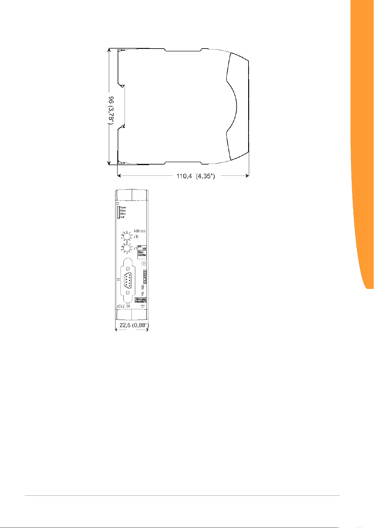
Illustration7: Side dimensions
Technical Data
Illustration8: Front dimensions
Gateway component for DeviceNetTM
38 / 38
 Loading...