

Page 1

User Manual
Gateway component for DMX
DO0262R00 • 1/26/2017
Page 2

Table of Contents KUNBUS GmbH
Table of Contents
1 General Information ........................................................................................................................3
1.1 Disclaimer..................................................................................................................................3
1.2 Notes Regarding this User Manual............................................................................................3
1.3 Validity .......................................................................................................................................3
1.4 Limitation of Liability ..................................................................................................................4
1.5 Customer Service ......................................................................................................................4
2 Safe Use ...........................................................................................................................................5
2.1 User ...........................................................................................................................................5
2.2 Symbols.....................................................................................................................................5
3 Overview ..........................................................................................................................................6
3.1 Functionality ..............................................................................................................................6
3.2 Control Elements .......................................................................................................................8
3.3 Status LEDs.............................................................................................................................11
4 Installation .....................................................................................................................................12
4.1 Preparations for Trouble-free Operation..................................................................................12
4.2 Requirements .........................................................................................................................14
4.3 Connecting Gateway Components..........................................................................................15
4.4 Installing a Gateway in the Control Cabinet ............................................................................16
4.5 Connecting a Power Supply ....................................................................................................17
4.6 Connecting a Gateway to the Fieldbus....................................................................................18
5 Configuration.................................................................................................................................19
5.1 Supported Size of the Process Data ......................................................................................19
5.2 Make the setting via the rotary switches..................................................................................20
5.3 Making the settings via the partner gateway component ........................................................22
6 Technical Data...............................................................................................................................24
6.1 Technical Data.........................................................................................................................24
ii DO0262R00-MGW-UM-DMX-EN
Page 3

1 General Information
1.1 Disclaimer
© 2016 KUNBUS GmbH, Denkendorf (Germany)
The contents of this user manual have been prepared by KUNBUS
GmbH with the utmost care. Due to technical development, KUNBUS
GmbH reserves the right to change or replace the contents of this
user manual without prior notice. You can always obtain the latest
version of the user manual at our homepage: www.kunbus.de
KUNBUS GmbH shall be liable exclusively to the extent specified in
General Terms and Conditions (www.kunbus.de/agb.html).
The contents published in this user manual are protected by
copyright. Any reproduction or use for the in-house requirements of
the user is permitted. Reproduction or use for other purposes is not
permitted without the express, written consent of KUNBUS GmbH.
Contraventions shall result in compensation for damages.
General Information
Trademark protection
– KUNBUS is a registered trademark of KUNBUS GmbH
– Windows® and Microsoft® are registered trademarks of Microsoft Corp.
KUNBUS GmbH
Heerweg 15 c
73770 Denkendorf
Germany
www.kunbus.de
1.2 Notes Regarding this User Manual
This user manual provides important technical information that can
enable you as a user to integrate the Gateway into your applications
and systems efficiently, safely and conveniently. It is intended for
trained, qualified personnel, whose sound knowledge in the field of
electronic circuits and expertise of DMX is assumed.
As an integral part of the module, the information provided here
should be kept and made available to the user.
1.3 Validity
This document describes the application of the KUNBUS Gateway
with the product number:
– PR100237, release 00
DO0262R00-MGW-UM-DMX-EN 3 / 25
Page 4

1.4 Limitation of Liability
Warranty and liability claims will lapse if:
– the product has been used incorrectly,
– damage is due to non-observance of the operating manual,
– damage is caused by inadequately qualified personnel,
– damage is caused by technical modification to the product (e.g.
soldering).
1.5 Customer Service
If you have any questions or suggestions concerning this product,
please do not hesitate to contact us:
KUNBUS GmbH
Heerweg 15 C
73770 Denkendorf
Germany
+49 (0)711 3409 7077
General Information
[email protected]
www.kunbus.de
DO0262R00-MGW-UM-DMX-EN
4 / 25
Page 5

2 Safe Use
2.1 User
The Gateway may only be assembled, installed and put into
operation by trained, qualified personnel. Before assembly, it is
absolutely essential that this documentation has been read carefully
and understood. Expertise in the following fields is assumed:
– electronic circuits,
– basic knowledge of DMX,
– work in electrostatic protected areas,
– locally applicable rules and regulations for occupational safety.
2.2 Symbols
The symbols used have the following meaning:
Safe Use
DANGER
CAUTION
NOTICE
Danger
Always observe this information!
There is a safety hazard that can lead to serious injuries and death.
Caution
There is a safety hazard that can result in minor injuries and material
damage.
Note
There is a safety hazard that can result in material damage.
DO0262R00-MGW-UM-DMX-EN 5 / 25
Page 6

3 Overview
3.1 Functionality
The KUNBUS Gateway is a protocol converter. It allows
communication between networks with different protocols.
Overview
Illustration1: Functionality as a slave
DO0262R00-MGW-UM-DMX-EN
6 / 25
Page 7

A Gateway consists of 2 gateway components that master one
specific protocol each. You can combine these gateway components
as you wish. This design offers you a high degree of flexibility, since
you can exchange the individual gateway components at any time.
The following gateway components are currently available as slaves:
– CANopen
– DeviceNet
– EtherCAT
– EtherNet/IP
– Modbus RTU
– Modbus TCP
– POWERLINK
– PROFIBUS
– PROFINET
– Sercos III
The gateway component for DMX can be operated as a master or
slave.
Overview
In addition, you can combine the gateway components with the
RevPi Core.
DO0262R00-MGW-UM-DMX-EN 7 / 25
Page 8

3.2 Control Elements
1
2
3
Front view
Overview
Illustration2: Front view
1 Status LEDs
2 Rotary coding switch
3 DMX connection
DO0262R00-MGW-UM-DMX-EN
8 / 25
Page 9
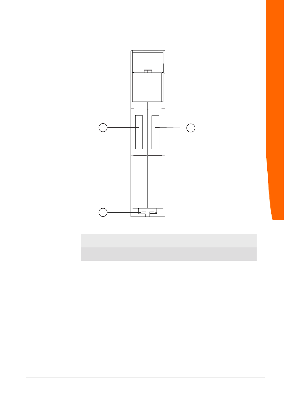
Top
1
1
2
Overview
Illustration3: Top
1 Interconnect ports
for interconnecting the gateway components.
2 Locking clamps
for securely attaching the gateway component to the DIN rail.
DO0262R00-MGW-UM-DMX-EN 9 / 25
Page 10
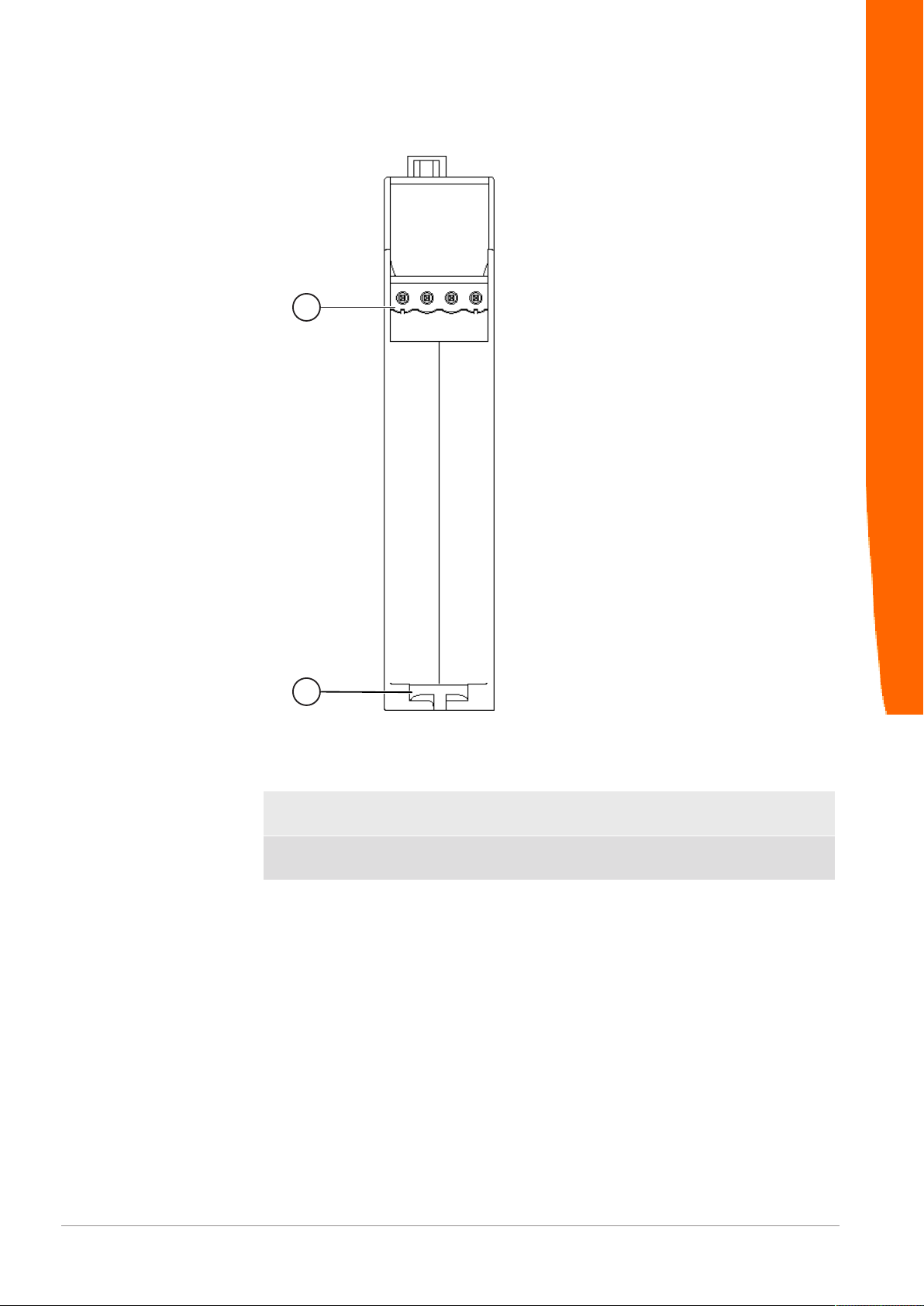
Bottom
1
2
Overview
Illustration4: Bottom
1 Mains connection
with 24 V power supply
2 Locking clamps
for securely attaching the gateway component to the DIN rail.
DO0262R00-MGW-UM-DMX-EN
10 / 25
Page 11

3.3 Status LEDs
The signals of the status LEDs for DMX have the following meaning:
Overview
LED
designation
Power off Gateway not running
Term on, green Bus termination not active
Traffic green, flashes DMX data active (master and slave
Signal Meaning
flashes, green Initialization phase not yet completed
on, green All system components are functioning
perfectly
flashes, red Correctable error (e.g. second gateway
component missing)
on, red Serious error/defect in the gateway
off Bus termination not active
mode)
red, on Slave mode: DMX data inactive
DO0262R00-MGW-UM-DMX-EN 11 / 25
Page 12

4 Installation
4.1 Preparations for Trouble-free Operation
In the following section we have compiled some general information
for you that is important for trouble-free operation. If you are already
acquainted with this topic, you can skip to the next section. There,
you will learn about which conditions are necessary for installing the
gateway.
Cable routing
Route your cables separately in cable groups. This will protect your
gateway from any unintended electromagnetic interferences.
The following groups should be routed separately from each other:
Group Line
A Data and power supply lines for:
DC voltage below 60V
AC voltage below 25V
B Data and power supply lines for:
DC voltage between 60V and 400V
AC voltage between 25 and 400V
C Power supply lines above 400V
Installation
– You can route cables of the same group together in cable ducts or
bundles.
– Cables of group A and B:
– Route the groups in separate bundles or
– in cable ducts at a minimum distance of 10 cm from each other.
– Cables of group C
– Route the groups in separate bundles or
– in cable ducts at a minimum distance of 50 cm from the other
groups.
Shielding
Shield your cables. This will reduce any unintended electromagnetic
interferences.
DO0262R00-MGW-UM-DMX-EN
12 / 25
Page 13

Potential equalization
Potential differences occur when devices are connected to different
earths. These potential differences cause malfunctions.
To prevent malfunctions, you have to route an equipotential
equalization conductor.
When doing so, bear in mind the following points:
– Select an equipotential equalization conductor with low impedance.
– Select the following as a reference value for the cross-section of the
potential equalization cable:
– 16 mm2 for potential equalization cables of up to 200 m in length
– 25 mm2 for potential equalization cables of more than 200 m in
length
– Use potential equalization cables made of copper or galvanized steel.
– Connect potential equalization cables extensively with the earth rail.
– The smallest surfaces possible should be sandwiched between
potential equalization cables and signal cables.
If the devices of the control system are connected by shielded signal
cables that are earthed on both sides, the impedance must be 10%
of the shielding impedance.
Installation
DO0262R00-MGW-UM-DMX-EN 13 / 25
Page 14
4.2 Requirements
The Gateway was designed for use in a control cabinet.
NOTICE
ü The protection class of the control cabinet must be equivalent to at least
IP54.
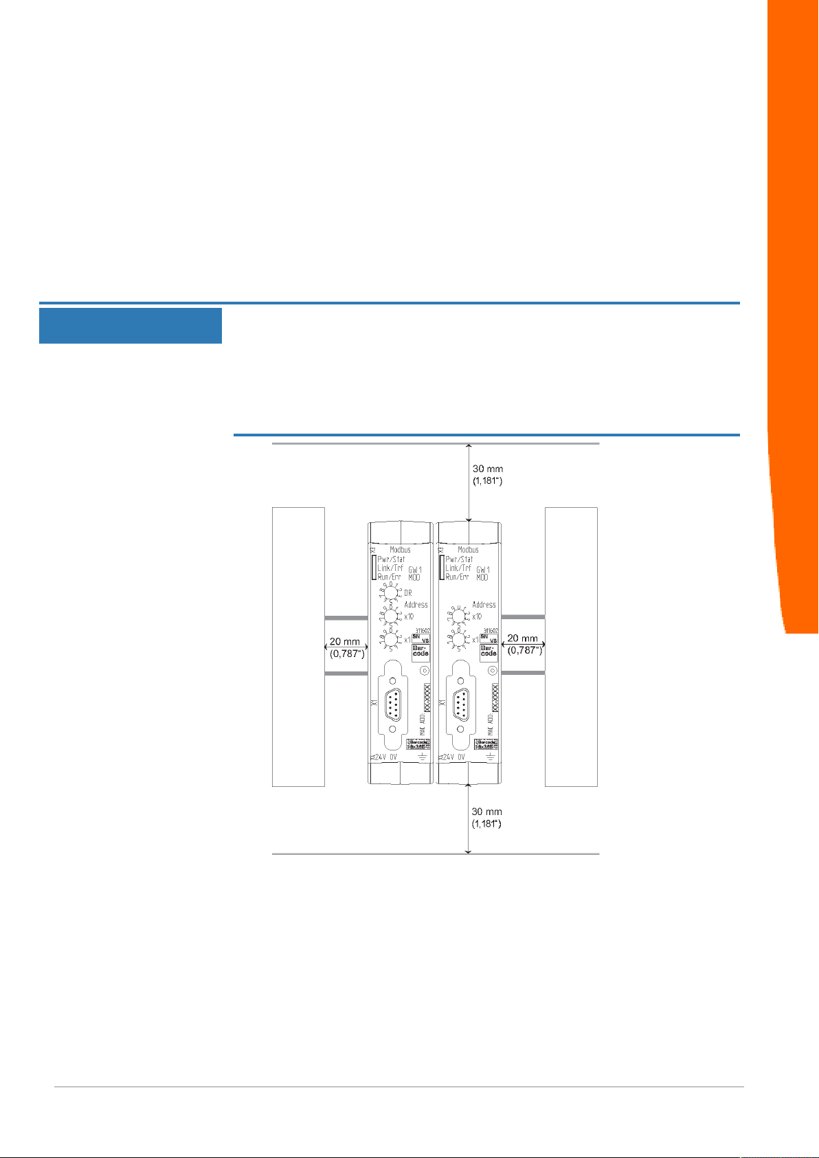
ü For installation in the control cabinet you need a DIN rail 35 x 7.5mm
(EN50022).
◦ Install the DIN rail horizontally in the control cabinet according to the
manufacturers' specifications. When doing so, make sure that the
Gateway is at a sufficient distance from other devices.
Your gateway could be damaged if temperatures are too high.
èMake sure that the ambient temperature in the control cabinet is less
than 60°C.
èKeep the ventilation slots unobstructed. These must not be covered by
cables etc.
èMaintain sufficient distance from other devices.
Installation
DO0262R00-MGW-UM-DMX-EN
Illustration5: Distances for installation
◦ Connect each gateway component individually to functional earth.
When doing so, make sure that the power supplies of both gateway
components have the same ground.
ð Your control cabinet now meets all requirements for installing the
gateway.
14 / 25
Page 15
4.3 Connecting Gateway Components
In order to attain a fully functional gateway, you have to interconnect
both gateway components.
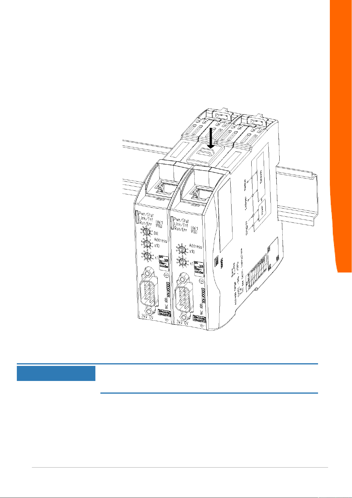
◦ Connect an interconnect port to each gateway component using the
plug-in jumper (product number PR100204).
◦
Installation
Illustration6: Connecting gateway components
ð You can now install the gateway in the control cabinet.
Only ever interconnect 2 gateway components.
NOTICE
If you connect additional components, severe defects could result on all
devices.
DO0262R00-MGW-UM-DMX-EN 15 / 25
Page 16
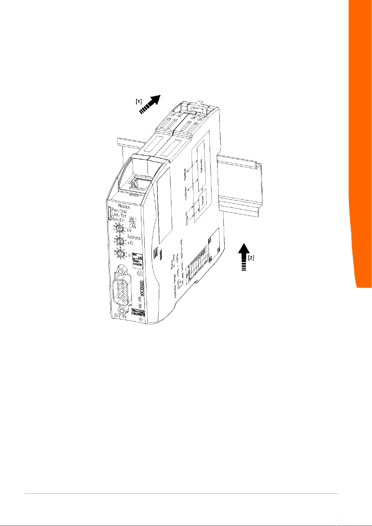
4.4 Installing a Gateway in the Control Cabinet
◦ Hold the raster element of the gateway on the DIN rail.
◦ Press down the locking elements towards the gateway.
◦ Make sure that the gateway is firmly attached to the DIN rail.
Installation
DO0262R00-MGW-UM-DMX-EN
16 / 25
Page 17
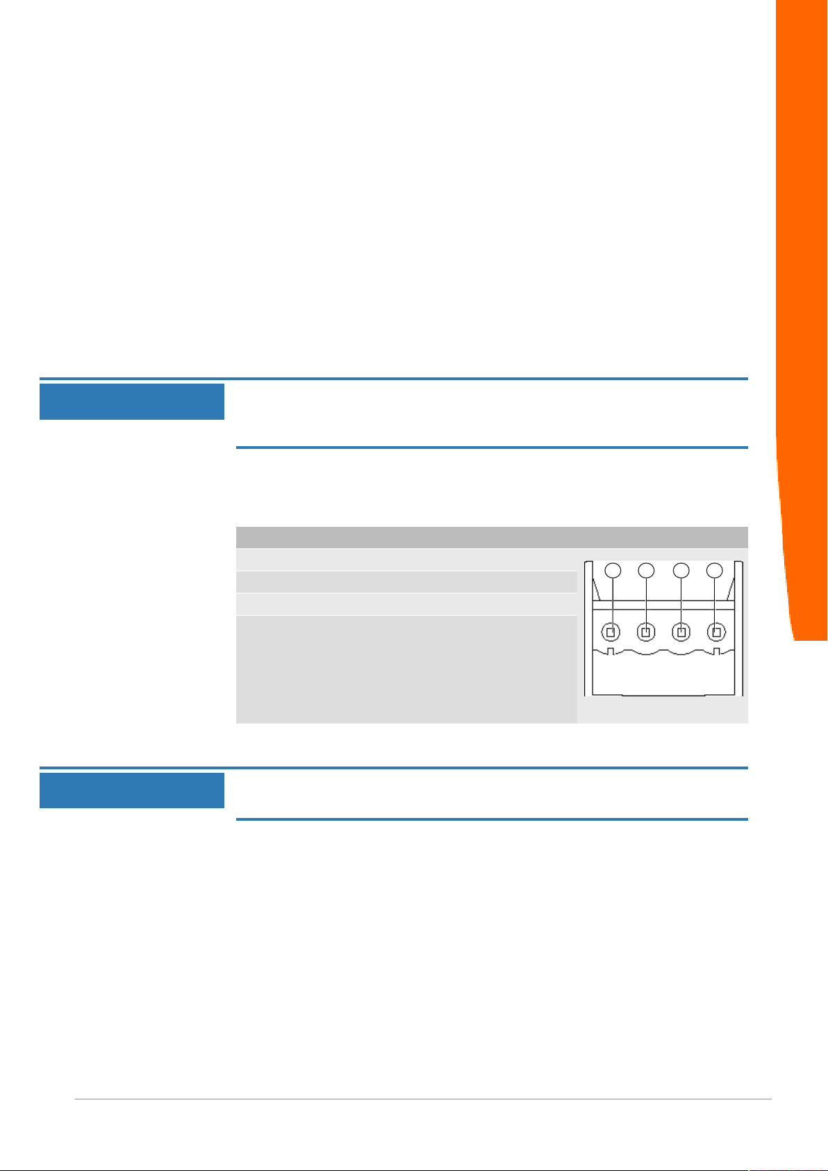
4.5 Connecting a Power Supply
3
1
2
4
To connect the gateway component to the power supply, you need a
spring-loaded terminal (e.g. Metz-Connect SP995xxVBNC).
You have to connect each gateway component separately to a power
supply. Never interconnect functional earth and GND, otherwise the
galvanic isolation between gateway GND and fieldbus ground will be
removed. Instead, connect the functional earth with low impedance to
the potential equalization. You can then dispense with this
connection if the shield of the fieldbus cable is connected to the
potential equalization with lower impedance when entering the
control cabinet.
Installation
NOTICE
NOTICE
Connect each of the two gateway components to the power supply
èEnsure in particular that no potential differences occur between the
GND pins (2).
Pin assignment:
Pin Assignment
1 24V for module supply
2 GND
3 Do not connect!
4 Functional earth
Do not connect GND to PE
This connection could cause unintended malfunctions.
DO0262R00-MGW-UM-DMX-EN 17 / 25
Page 18

4.6 Connecting a Gateway to the Fieldbus
To connect the gateway component to DMX, you need an adapter.
The table below shows an example connection to a 3-pole XLR plug.
Connection Function Pin assignment for
XLR plug
1 - 2 - 3 - 4 Earth (screen) 1
5 DMX + 3
6 DMX - 2
7 - 8 - -
Installation
DO0262R00-MGW-UM-DMX-EN
18 / 25
Page 19
5 Configuration
You can operate the gateway component as a master or a slave.
In "Sender" function mode, the gateway component sends data to
slaves and performs the function of a bus master (as for a DMX
lighting control desk, for example).
In "Receiver" function mode, the gateway component receives data
from a bus master and performs the function of an actuator (as for a
lighting control, for example).
You have 2 options for configuration of the gateway components:
– Make the setting via the rotary switches
– Making the settings via the partner gateway component
5.1 Supported Size of the Process Data
The gateway component for DMX supports process data up to a
length of 512 bytes per direction.
Configuration
NOTICE
Bear in mind that the maximum length of the process data is always
determined by the fieldbus with the shorter data length.
Example:
CANopen supports 512 bytes
PROFIBUS supports 244 bytes per direction
In conjunction with PROFIBUS/ CANopen, this means that 488 bytes
are transmitted and updated cyclically.
DO0262R00-MGW-UM-DMX-EN 19 / 25
Page 20
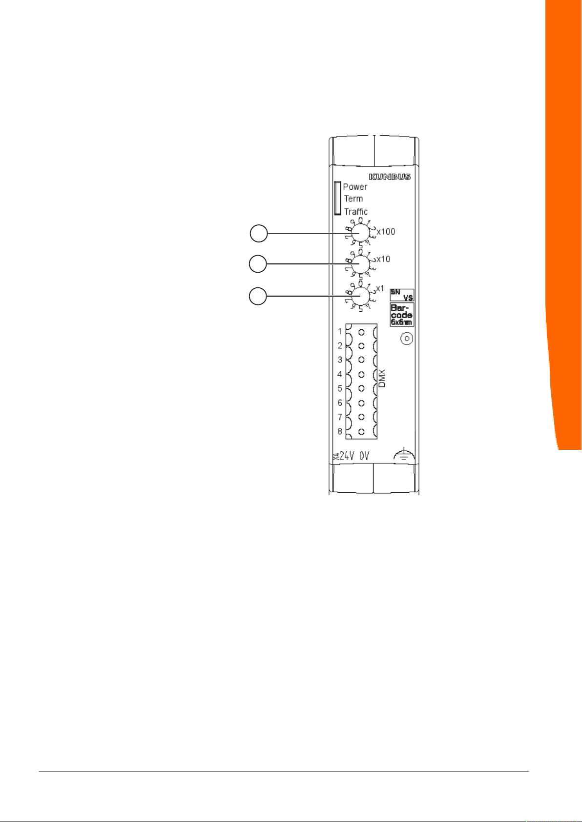
5.2 Make the setting via the rotary switches
1
2
3
You can set the function mode and the addressing at the rotary
switches.
Configuration
DO0262R00-MGW-UM-DMX-EN
Illustration7: Rotary switch
With each rotary switch, you can set a decimal from 0-9. These 3
values together allow you to set a value range of 0-999.
– Switch 0x100 (1) determines the hundreds digit
– Switch 0x10 (2) determines the tens digit
– Switch 0x1 (3) determines the ones digit
Example: You want to set the value 234.
Switch setting:
– Switch 1: 2
– Switch 2: 3
– Switch 3: 4
The values are interpreted accordingly in the following table:
20 / 25
Page 21

Value Switch setting
at the switch
1 2 3
0 0 0 0 Configuration is via the partner gateway component
1 0 0 1 Receiver mode, bus termination inactive, start
[…]
512 5 1 2 Receiver mode, bus termination inactive, start
513 5 1 3 Sender mode, bus termination active, 512 bytes are
[…]
999 9 9 9 Sender mode, bus termination active, 512 bytes are
Function mode
address = 1
address = 512
transmitted
transmitted
Restart the gateway component to activate new settings.
Examples:
Configuration
Receiver mode, start address
73
Sender mode
Partner gateway mode
To set a DMX receiver with inactive bus termination at start address
73, you must set the switch as follows:
SW_1 = 0
SW_2 = 7
SW_3 = 3
To set a DMX sender with activated bus termination, which transmits
512 channels, you must set the switch as follows:
SW_1 = 5
SW_2 = 1
SW_3 = 3
To configure via a partner gateway, you must set the switch as
follows:
SW_1 = 0
SW_2 = 0
SW_3 = 0
DO0262R00-MGW-UM-DMX-EN 21 / 25
Page 22

5.3 Making the settings via the partner gateway component
You can also make the settings for the DMX gateway component
also via a partner gateway component.
In this configuration mode, you as a "sender" can send a maximum
510 bytes, since 2 bytes are required for the configuration.
To make the settings:
◦ Set the rotary switch of the DMX gateway component to "0, 0, 0"
◦ Use the master software to configure the individual bits of the first 2
bytes of the DMX data.
They are assigned as follows:
ByteBit Function Setting options
Configuration
0 0
(LSB)
1
2
3
4
5
6
7
1 0
1
(MSB)
2 - 3 - 4 - 5 Zero data
6 Mode 0= Sender
7 Termination 0=Termination active
Number
A 9-Bit value range can be set
here. The meaning of this value
differs depending on the mode.
determine the behavior with a
communication interruption.
"Sender" function mode
Number of channels to be
sent
: 1-510
Default value: 510
! Since the first two bytes are
occupied by the configuration data, a maximum 510
bytes of DMX data can be
transmitted in sender mode.
"Receiver" function mode
Receiver address: 1-512
default value: 1
0= inactive
Last received data are retained
1= active
After 1s communication interruption, all data bytes are
set to 0
1= Receiver
1= Termination inactive
DO0262R00-MGW-UM-DMX-EN
22 / 25
Page 23
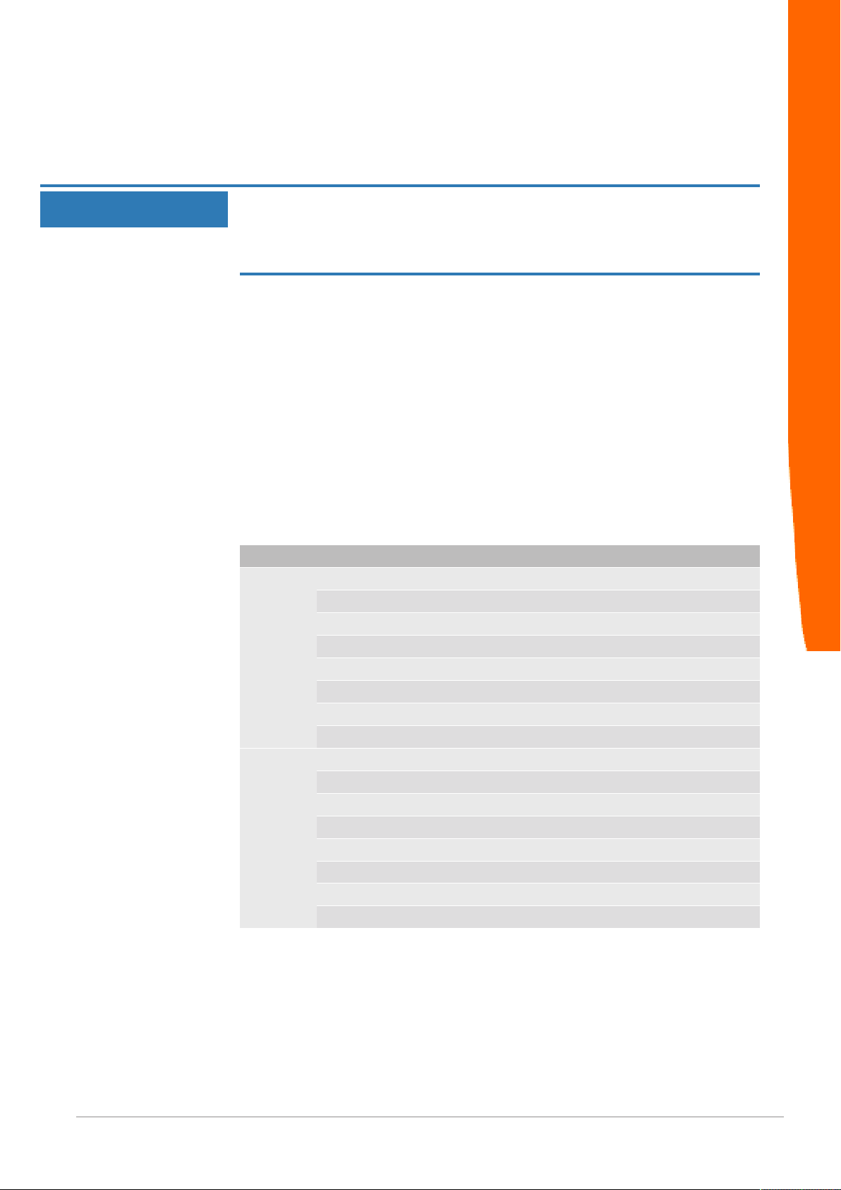
Termination
The termination resistor prevents reflexions from occurring at the end
of the connection that could cause errors in the data communication.
The integrated termination resistor is 120 Ω.
NOTICE
Activate the termination resistor only if the module is the first or last
subscriber of the connection.
Errors in the data communication may occur if the termination resistor is
activated while the module is connected at a central position in the network.
Example:
– Mode
– Sender, Byte 2, do not set Bit 6
– Send data (number)
– Send 73 channels, channels 7310 := 49
– Termination
– Inactive: Byte 2, set Bit 7
– Zero data
– Inactive: Byte 2, do not set Bit 5
Byte Bit Setting
0 0 1
1 0
2 0
3 1
4 0
5 0
6 1
7 0
1 0 0
1 0
2 0
3 0
4 0
5 0
6 0
7 1
16
Configuration
DO0262R00-MGW-UM-DMX-EN 23 / 25
Page 24

6 Technical Data
6.1 Technical Data
Dimensions
Width 22.5 mm
Height 96 mm
Depth 110.4 mm
Weight 90 g
Electrical data
Power supply 24 V DC
Power consumption during operation
(cyclical data exchange)
Status display LED
Environmental conditions
Ambient temperature 0 – 60 °C
Storage temperature - 25 – 60 °C
Humidity 93% (at 40 °C)
Condensing Not allowed
Protection class
Control cabinet
Housing
Terminal area
Technical Data
100mA
IP54
IP20
IP20
Assembly data
DIN rail 35 x 7.5 mm
Height 96 mm
Depth 110.4 mm
DMX protocol
Protocol DMX 512
Communication type Unidirectional
A sender sends the data without receiving feedback. A receiver accepts
the data on the bus without feed-
back.
Baudrate 250 kBaud
Transmission RS 485
Byte transmission 8N2 (8 data bits, no parity, 2 stop
bits)
Special feature A DMX package starts with 88 us (22
bit lengths) low level (logical 0). This
section is called "break".
DO0262R00-MGW-UM-DMX-EN
24 / 25
Page 25
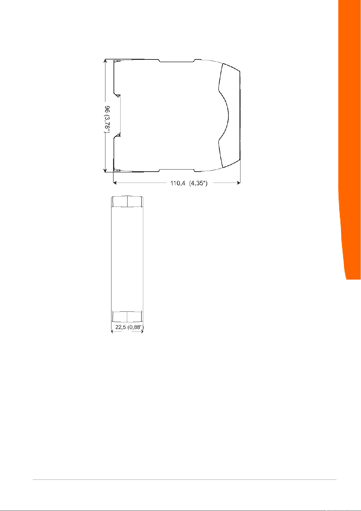
Illustration8: Side dimensions
Technical Data
Illustration9: Front dimensions
DO0262R00-MGW-UM-DMX-EN 25 / 25
 Loading...