


User manual
Gateway component Modbus TCP
PR100088 • 1/17/2019

Table of Contents KUNBUS
Table of Contents
1 General Information ........................................................................................................................3
1.1 Disclaimer..................................................................................................................................3
1.2 Notes Regarding this User Manual............................................................................................3
1.3 Validity .......................................................................................................................................4
1.4 Limitation of Liability ..................................................................................................................4
1.5 Customer Service ......................................................................................................................4
2 Safe Use ...........................................................................................................................................5
2.1 User ...........................................................................................................................................5
2.2 Symbols.....................................................................................................................................5
2.3 Data safety ................................................................................................................................6
3 Overview ..........................................................................................................................................7
3.1 Functionality ..............................................................................................................................7
3.2 Control Elements .......................................................................................................................8
3.3 Status LEDs.............................................................................................................................11
4 Installation .....................................................................................................................................12
4.1 Preparations for Trouble-free Operation..................................................................................12
4.2 Requirements .........................................................................................................................14
4.3 Connecting Gateway Components..........................................................................................15
4.4 Installing a Gateway in the Control Cabinet ............................................................................16
4.5 Connecting a Power Supply ....................................................................................................17
4.6 Connecting a Gateway to the Fieldbus....................................................................................18
5 Configuration.................................................................................................................................19
5.1 Supported size of Process Data ..............................................................................................19
5.2 Address Assignment................................................................................................................19
5.3 Configure Modbus TCP ..........................................................................................................20
6 Integrated servers .........................................................................................................................22
6.1 FTP-Server ..............................................................................................................................22
6.2 Webserver ...............................................................................................................................22
6.3 Install firmware update ............................................................................................................24
7 Technical Data...............................................................................................................................29
7.1 Technical Data.........................................................................................................................29
ii Gateway component ModbusTCP

1 General Information
1.1 Disclaimer
© 2019 KUNBUS GmbH, Denkendorf (Deutschland)
The contents of this user manual have been compiled by KUNBUS
GmbH with the greatest possible care. Due to technical
developments, KUNBUS GmbH reserves the right to change or
exchange the contents of this user manual without prior notice. You
can always obtain the latest version of the user manual from our
homepage: www.kunbus.com
KUNBUS GmbH shall be liable exclusively to the extent specified in
the General Terms and Conditions (www.kunbus.de/agb.html).
The contents published in this user manual are protected by
copyright. Reproduction or use is permitted for the internal use of the
user. Duplication or use for other purposes is not permitted without
the express written consent of KUNBUS GmbH. Contraventions will
result in damages.
General Information
Trademark protection
– KUNBUS is a registered trademark of KUNBUS GmbH.
– Windows® und Microsoft® are registered trademark of Microsoft, Corp.
KUNBUS GmbH
Heerweg 15 c
73770 Denkendorf
Germany
www.kunbus.de
1.2 Notes Regarding this User Manual
This user manual provides important technical information that can
enable you as a user to integrate the Gateway into your applications
and systems efficiently, safely and conveniently. It is intended for
trained, qualified personnel, whose sound knowledge in the field of
electronic circuits and expertise of Modbus TCP is assumed.
As an integral part of the module, the information provided here
should be kept and made available to the user.
Gateway component ModbusTCP 3 / 30

1.3 Validity
This document describes the application of the KUNBUS Gateway
with the product number:
– PR100088, Release 00
– PR100088, Release 01
1.4 Limitation of Liability
Warranty and liability claims will lapse if:
– the product has been used incorrectly,
– damage is due to non-observance of the operating manual,
– damage is caused by inadequately qualified personnel,
– damage is caused by technical modification to the product (e.g.
soldering).
1.5 Customer Service
General Information
If you have any questions or suggestions concerning this product,
please do not hesitate to contact us:
KUNBUS GmbH
Heerweg 15 C
73770 Denkendorf
Germany
+49 (0)711 3409 7077
support@kunbus.de
www.kunbus.de
Gateway component ModbusTCP
4 / 30

2 Safe Use
2.1 User
The Gateway may only be assembled, installed and put into
operation by trained, qualified personnel. Before assembly, it is
absolutely essential that this documentation has been read carefully
and understood. Expertise in the following fields is assumed:
– electronic circuits,
– basic knowledge of Modbus TCP,
– work in electrostatic protected areas,
– locally applicable rules and regulations for occupational safety.
2.2 Symbols
The symbols used have the following meaning:
Safe Use
DANGER
CAUTION
NOTICE
Danger
Always observe this information!
There is a safety hazard that can lead to serious injuries and death.
Caution
There is a safety hazard that can result in minor injuries and material
damage.
Note
There is a safety hazard that can result in material damage.
Gateway component ModbusTCP 5 / 30

2.3 Data safety
Please note that Gatewayis not suitable for use in unprotected
networks (e.g. the Internet).
Use Gateway in a secured network:
.
◦ Seal off your network so that no direct access via the Internet is
allowed.
◦ Immediately change the default password for the web server. You can
find out how to do this in the chapter "Changing the password". Select a
secure new password.
◦ Check our website regularly for the latest software security alerts and
updates for your product. Install the security updates provided by us.
If you do not follow these instructions, it is possible that your module
data may be manipulated.
Safe Use
Gateway component ModbusTCP
6 / 30

3 Overview
3.1 Functionality
The KUNBUS Gateway is a protocol converter. It allows
communication between networks with different protocols.
Overview
Illustration1: Functionality as a slave
A Gateway consists of 2 gateway components that master one
specific protocol each. You can combine these gateway components
as you wish. This design offers you a high degree of flexibility, since
you can exchange the individual gateway components at any time.
The following gateway components are currently available as slaves:
– CANopen
– DeviceNet
– EtherCAT
– EtherNet/IP
– Modbus RTU
– Modbus TCP
– POWERLINK
– PROFIBUS
– PROFINET
– Sercos III
The gateway component for DMX can be operated as a master or
slave.
Gateway component ModbusTCP 7 / 30
In addition, you can combine the gateway components with the
1
2
3
RevPi Core.
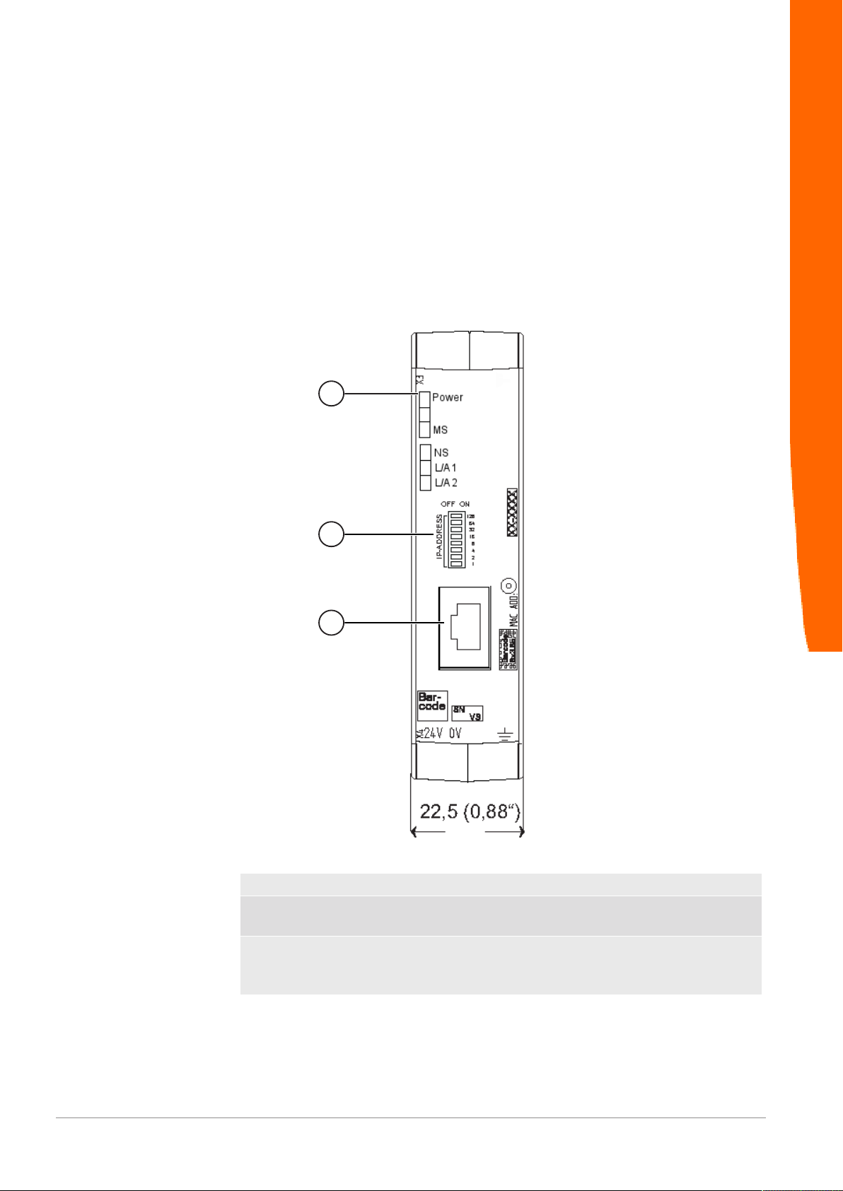
3.2 Control Elements
Front view
Overview
Gateway component ModbusTCP
Illustration2: Front view
1 Status LEDs
2 Coding switch
8-pin DIP switch for setting the IP address.
3 Fieldbus connection
RJ45 socket for the connection to the fieldbus (2 sockets in all,
s. figure top view)
8 / 30
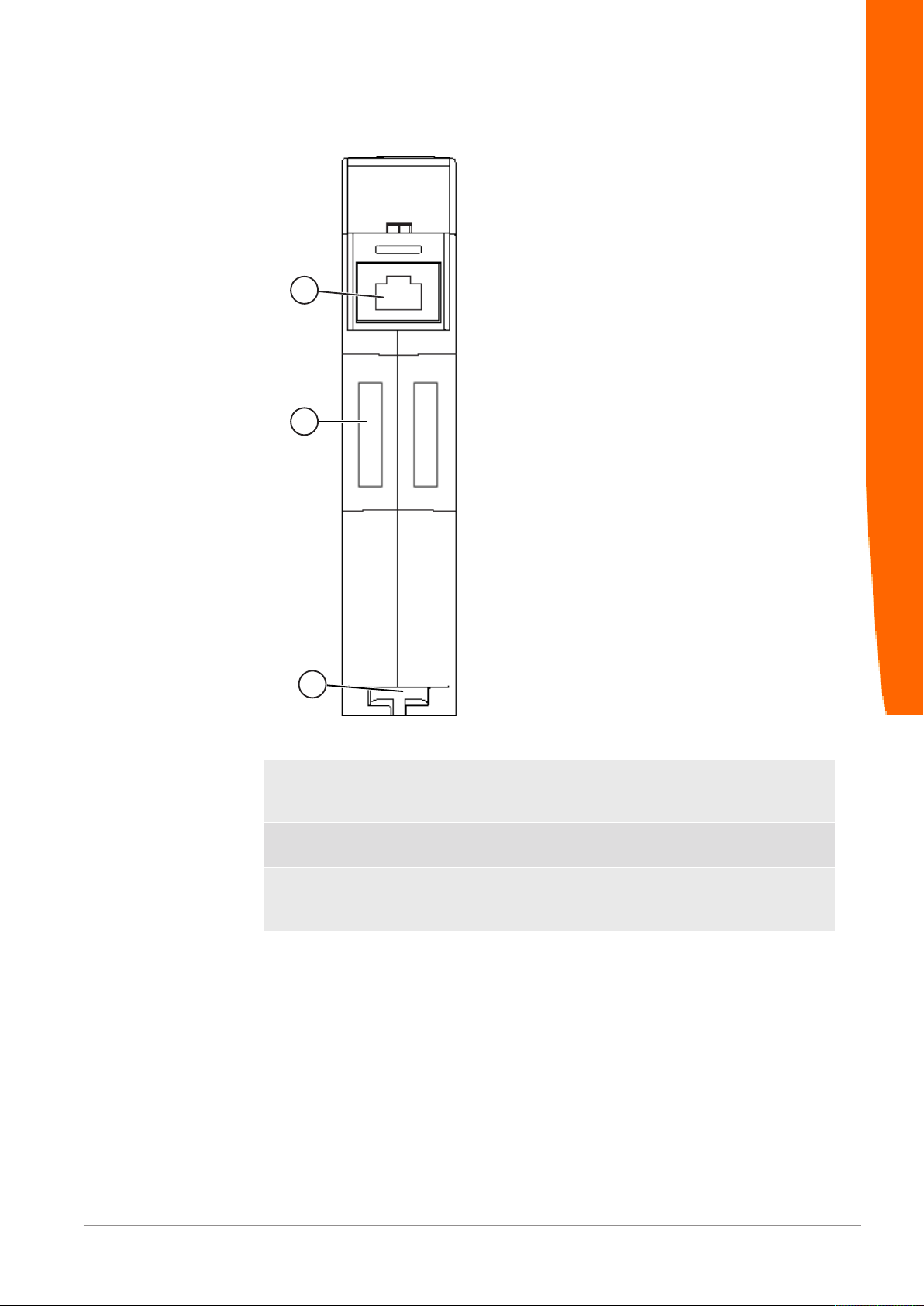
Top view
1
2
3
Overview
Illustration3: Top view
1 Fieldbus connection
RJ45 socket for the connection to the fieldbus (total 2 pieces,
see picture front view)
2 Interconnect ports
for connecting the gateway components to each other
3 Locking clamp
for secure fastening of the gateway component on the top-hat
rail
Gateway component ModbusTCP 9 / 30
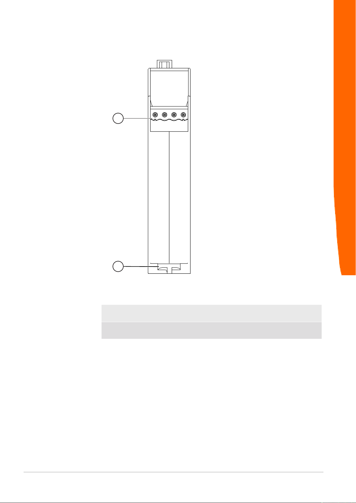
Bottom view
1
2
Overview
Illustration4: Bottom view
1 Power supply
with 24 V supply voltage
2 Locking clamp
for secure mounting of the gateway component on the top-hat rail
Gateway component ModbusTCP
10 / 30

3.3 Status LEDs
The signals of the status LEDs for Modbus TCP have the following
meaning:
LED designation Signal Meaning
Power off Gateway component not running
blinks, green Initialization phase not yet completed
on, green Operational
flashes, red Correctable error (e.g. second gateway
on, red Serious error/defect in the gateway
MS off Gateway component is not running
blinks, green Configuration not completed
on, green Operation, gateway component runs
NS off Gateway component is not running
blinks, green Standby mode, no data exchange via
on, green Connection is established, data is ex-
L/A 1 + 2 off No connection
green Connection to another device. No data
blinks, green Connection established. Data ex-
Overview
component missing)
without errors
Modbus/TCP
changed
exchange takes place.
change takes place.
Gateway component ModbusTCP 11 / 30

4 Installation
4.1 Preparations for Trouble-free Operation
In the following section we have compiled some general information
for you that is important for trouble-free operation. If you are already
acquainted with this topic, you can skip to the next section. There,
you will learn about which conditions are necessary for installing the
gateway.
Cable routing
Route your cables separately in cable groups. This will protect your
gateway from any unintended electromagnetic interferences.
The following groups should be routed separately from each other:
Group Line
A Data and power supply lines for:
DC voltage below 60V
AC voltage below 25V
B Data and power supply lines for:
DC voltage between 60V and 400V
AC voltage between 25 and 400V
C Power supply lines above 400V
Installation
– You can route cables of the same group together in cable ducts or
bundles.
– Cables of group A and B:
– Route the groups in separate bundles or
– in cable ducts at a minimum distance of 10 cm from each other.
– Cables of group C
– Route the groups in separate bundles or
– in cable ducts at a minimum distance of 50 cm from the other
groups.
Shielding
Shield your cables. This will reduce any unintended electromagnetic
interferences.
Potential equalization
Potential differences occur when devices are connected to different
earths. These potential differences cause malfunctions.
Gateway component ModbusTCP
12 / 30

To prevent malfunctions, you have to route an equipotential
equalization conductor.
When doing so, bear in mind the following points:
– Select an equipotential equalization conductor with low impedance.
– Select the following as a reference value for the cross-section of the
potential equalization cable:
– 16 mm2 for potential equalization cables of up to 200 m in length
– 25 mm2 for potential equalization cables of more than 200 m in
length
– Use potential equalization cables made of copper or galvanized steel.
– Connect potential equalization cables extensively with the earth rail.
– The smallest surfaces possible should be sandwiched between
potential equalization cables and signal cables.
If the devices of the control system are connected by shielded signal
cables that are earthed on both sides, the impedance must be 10%
of the shielding impedance.
Installation
Gateway component ModbusTCP 13 / 30

4.2 Requirements
NOTICE
The Gateway was designed for use in a control cabinet.
Installation
ü The protection class of the control cabinet must be equivalent to at least
IP54.
ü For installation in the control cabinet you need a DIN rail 35 x 7.5mm
(EN50022).
◦ Install the DIN rail horizontally in the control cabinet according to the
manufacturers' specifications. When doing so, make sure that the
Gateway is at a sufficient distance from other devices.
Your gateway could be damaged if temperatures are too high.
èMake sure that the ambient temperature in the control cabinet is less
than 60°C.
èKeep the ventilation slots unobstructed. These must not be covered by
cables etc.
èMaintain sufficient distance from other devices.
Gateway component ModbusTCP
Illustration5: Distances for installation
◦ Connect each gateway component individually to functional earth.
When doing so, make sure that the power supplies of both gateway
components have the same ground.
ð Your control cabinet now meets all requirements for installing the
gateway.
14 / 30

4.3 Connecting Gateway Components
In order to attain a fully functional gateway, you have to interconnect
both gateway components.
◦ Connect an interconnect port to each gateway component using the
plug-in jumper (product number PR100204).
◦
Installation
Illustration6: Connecting gateway components
ð You can now install the gateway in the control cabinet.
Only ever interconnect 2 gateway components.
NOTICE
If you connect additional components, severe defects could result on all
devices.
Gateway component ModbusTCP 15 / 30

4.4 Installing a Gateway in the Control Cabinet
◦ Hold the raster element of the gateway on the DIN rail.
◦ Press down the locking elements towards the gateway.
◦ Make sure that the gateway is firmly attached to the DIN rail.
Installation
Gateway component ModbusTCP
16 / 30

4.5 Connecting a Power Supply
3
1
2
4
NOTICE
To connect the gateway component to the power supply, you need a
spring-loaded terminal (e.g. Metz-Connect SP995xxVBNC).
You have to connect each gateway component separately to a power
supply. Never interconnect functional earth and GND, otherwise the
galvanic isolation between gateway GND and fieldbus ground will be
removed. Instead, connect the functional earth with low impedance to
the potential equalization. You can then dispense with this
connection if the shield of the fieldbus cable is connected to the
potential equalization with lower impedance when entering the
control cabinet.
Connect each of the two gateway components to the power supply
èEnsure in particular that no potential differences occur between the
GND pins (2).
Pin assignment:
Pin Assignment
1 24V for module supply
2 GND
3 Do not connect!
4 Functional earth
Installation
NOTICE
Do not connect GND to PE
This connection could cause unintended malfunctions.
Gateway component ModbusTCP 17 / 30

4.6 Connecting a Gateway to the Fieldbus
To connect the gateway component to Modbus TCP, you need Two
RJ45 connectors.
The pin assignment complies with the Ethernet standard.
Installation
Gateway component ModbusTCP
18 / 30

5 Configuration
5.1 Supported size of Process Data
The gateway component for Modbus TCP supports process data up
to a length of 512 bytes per direction.
Configuration
NOTICE
5.2 Address Assignment
Assign IP address manually:
Get IP address from DHCP
server
Setting the IP address via the
master software
Bear in mind that the maximum length of the process data is always
determined by the fieldbus with the shorter data length.
Set IP address
With the 8-pole address switch you can set the IP address of the
Gateways.
You can set values in binary format between 0-255.
◦ Stellen Sie eine beliebige Adresse zwischen 1-254 ein
ð The gateway component uses the address 192.168.0.X , the Netork
mask 255.255.255.0 and the Gateway 192.168.0.1
◦ Open the website http://192.168.0.X
◦ Log in:
Login data for initial logon:
User: Admin
Password: 1701
◦ Click on the "Change Configuration" button.
◦ Set the desired IP address.
◦ Confirm the entry with the "Apply" button.“
◦ Set all address switches to "0".
◦ Restart the gateway component by switching it off and on again.
ð The set IP address is now used.
◦ Set the value "255" (all switches in the direction of the numbers) to
activate the DHCP mode.
ð The IP address is automatically assigned by the DHCP server.
◦ Set the value to "0" (all switches to "Off").
ð The gateway component uses the IP address that was last set via
the software.
◦ You can change this IP address at any time via the Modbus/TCP
protocol or the website.
◦ Restart the gateway component by switching it off and on again.
ð The set IP address is now used.
Gateway component ModbusTCP 19 / 30

Memory areas
5.3 Configure Modbus TCP
Modbus TCP - Addresses and access functions
Predefined memory areas are available for addressing the process
data. Optionally, you can access the input and output data areas bit
by bit (using coils) or word by word.
Register area for word by word access
Configuration
Address area Use Access Access
type
1 - 256 Input Register Read Only Holding/In-
put *
1025 - 1280 Output Register Read/Write Holding Values that are delivered to the other
4097/0x1001 Gateway-Status Read Only Holding Displays the connection status to the
4098/0x1002 Fieldbus status
of the other
gateway component.
4099/0x1003 IP address Read/Write Holding IP address High Word
4100/0x1004 IP address Read/Write Holding IP address Low Word
4101/0x1005 Network mask Read/Write Holding Network mask High Word
4102/0x1006 Network mask Read/Write Holding Network mask Low Word
4103/0x1007 Gateway ad-
dress
4104/0x1008 Gateway ad-
dress
4105/0x1009 Max. number of
Modbus/TCP
connections
4106/0x100a Current number
of Modbus/TCP
connections.
Read Only Holding 0x00 Fieldbus not connected. Make
Read/Write Holding Gateway address High Word
Read/Write Holding Gateway address Low Word
Read/Write Holding Displays the maximum number of Mod-
Read Only Holding Shows how many Modbus/TCP connec-
Meaning
Values provided by the other gateway
component
gateway component.
other gateway component.
0x01 Initialization, hardware is
checked.
0x02 Connection to the other gateway
component is checked.
0x03 Other gateway component de-
tected.
0x04 Communication to the other
gateway component established.
check all connections.
0x01 Fieldbus connected, no data
communication. Check whether
an IP address is set.
0x02 Gateway component configured,
no data communication.
0x03 Cyclic data exchange.
bus/TCP connections that can be
present at the same time.
value range: 2-20
tions are currently available.
Gateway component ModbusTCP
20 / 30

4107/0x101b Write Timeout Read/Write Holding The Write-Timeout function is active if
this register contains a value > 0. It indicates the time interval at which at least
one of the output registers must be written. As soon as the time has passed
since the last write, all output registers
are set to the default value 0..
4108/0x100c Reset Read/Write Holding Restarts the gateway component if
0x4b42 is written here.
*Input and holding registers are not distinguished. They can be read via function code 0x04.
Register ranges for bitwise access:
Configuration
Address area Use Access Access
type
1 - 3840 Input Bits (Coil) Read Only Holding/In-
put*
16385 - 20224 Output Bits
(Coil)
Read/Write Holding Values that are supplied to the other
*Input and Holding Register are not differentiated. They can be read using function code 0x004.
Meaning
Values that the other gateway component supplies.
gateway component..
Functions
You can access the data area of the gateway component using the
following functions:
Function
code
0x01 Read data bit by bit read coils 2000 Bit
0x02 read discrete inputs
0x05 Write data bit by bit write single coil 1 Bit
0x0f write multiple coils 1968 Bit
0x03 Read data word by word read holding registers 125 Words
0x04 read input registers
0x06 Write data word by word write single register 123 Words
0x10 write multiple registers
0x16 mask write register
0x17 Read and rite data word by
Use Description Max. size per telegram
word
read/write multiple registers
read 125 Words
write 121 Words
Gateway component ModbusTCP 21 / 30

6 Integrated servers
6.1 FTP-Server
The FTP server is necessary to update HTML files of the web server
and to transfer firmware updates to the module.
You can access the FTP server from user level 2. The same
credentials are valid as for the web server. The "Level" is defined in
the file "password.xml". You can find out how to do this in the section
„Logging on to the web server“. [}22]
Integrated servers
Web server files
The user can:
The files for the web server can be found in the subfolder "Web"“.
6.2 Webserver
The Gateway has a web server. You can access it from any browser.
Access web server
◦ Verbinden Sie das Gateway mit dem PC.
◦ Open your browser.
◦ Enter the IP address as URI(e.g.: http://192.168.0.8)
ð You can log in now.
Log on to web server
You can log on to the web server as an administrator or as a user..
– Read process data of the Gateway.
Logon data (default):
The administrator can:
Gateway component ModbusTCP
Username: User
Password: 1111
– Change passord
– Change network settings
Logon data (default):
Username: Admin
Password: 1701
22 / 30

Create user
To be able to check and manage login data, you must create a file
named "password.xml" in the main directory of the module.
In this file, define the following 3 XML elements for each user:
– <UserX>,
– <PasswordX>,
– <LevelX>.
X represents a digit between 0 and 9. Assign a digit to each user.
Make sure that the digit is not already used for another user.
User name and password may consist of up to 20 characters.
Spaces are allowed. At "Level" you have to enter a positive integer. If
this is at least 2, then the user is an "administrator".
Example for a "password.xml“:
<?xml version=“1.0“ encoding=“UTF-8“?>
<Passwords>
<User0>NutzerEins</User0>
<Password0>93h31m</Password0>
Integrated servers
<Level0>1</Level0>
<User1>NutzerZwei</User1>
<Password1>53cr3t</Password1>
<Level1>3</Level1>
</Passwords>
Tip! As admin you can change the password directly in the web
server.
Display process data
The transmitted data can be displayed cyclically for the interfaces
available in the selected mode..
Click on the "Show" buttons to view the process data of the desired
input and output area. The following example shows the process
data of the fieldbus.
Gateway component ModbusTCP 23 / 30
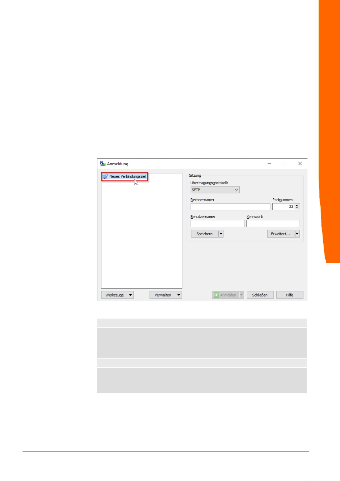
6.3 Install firmware update
The following pages describe how to install a firmware update on a
gateway component with a web server. We use the program
"WinSCP" for this purpose: However, you can also use another FTP
program for this purpose..
Conditions:
ü Your gateway is on your network.
ü The network interface is correctly configured.
ü You have installed an FTP program on your PC.
◦ Open your FTP program.
◦ Click on "New connection destination"..
Integrated servers
Gateway component ModbusTCP
◦ Enter the following values:
Transmission protocol FTP
Computer name IP address of the gateway compo-
nent.
The following address is used on de-
livery: 192.168.0.8
Port number
User name Username for the web server.
21
The following user name is used on
delivery: "Admin“
24 / 30
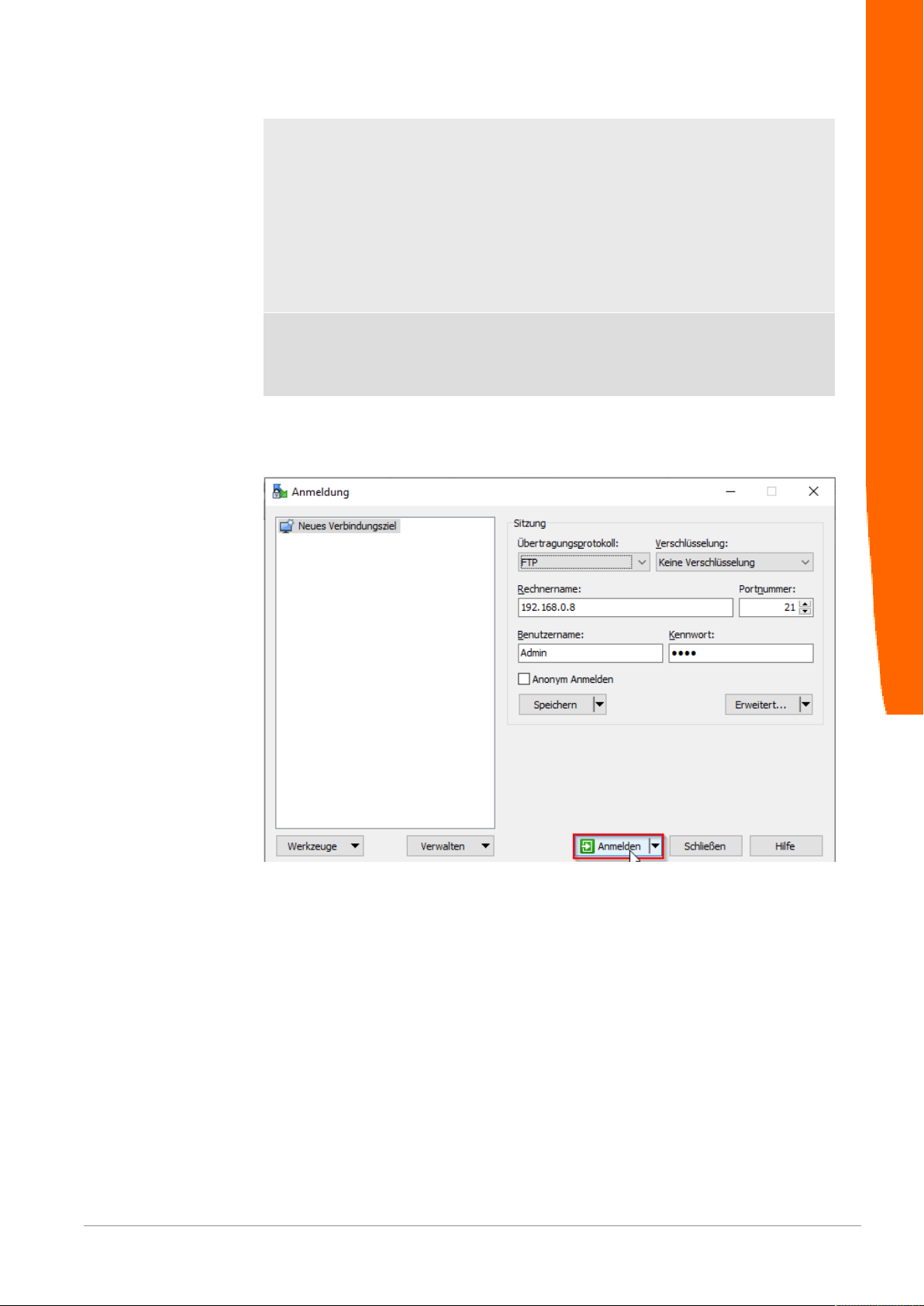
Password Password for the web server.
The following password is used on
delivery: „1701“
For reasons of data security, we rec-
ommend that you change your pass-
word as quickly as possible and do
not continue to use the stored val-
ues. You can change your password
via the web server.
Safe You can optionally save these set-
tings. This allows you to access the
gateway component more quickly via
FTP in the future.
◦ Click on "Login“
Integrated servers
Gateway component ModbusTCP 25 / 30
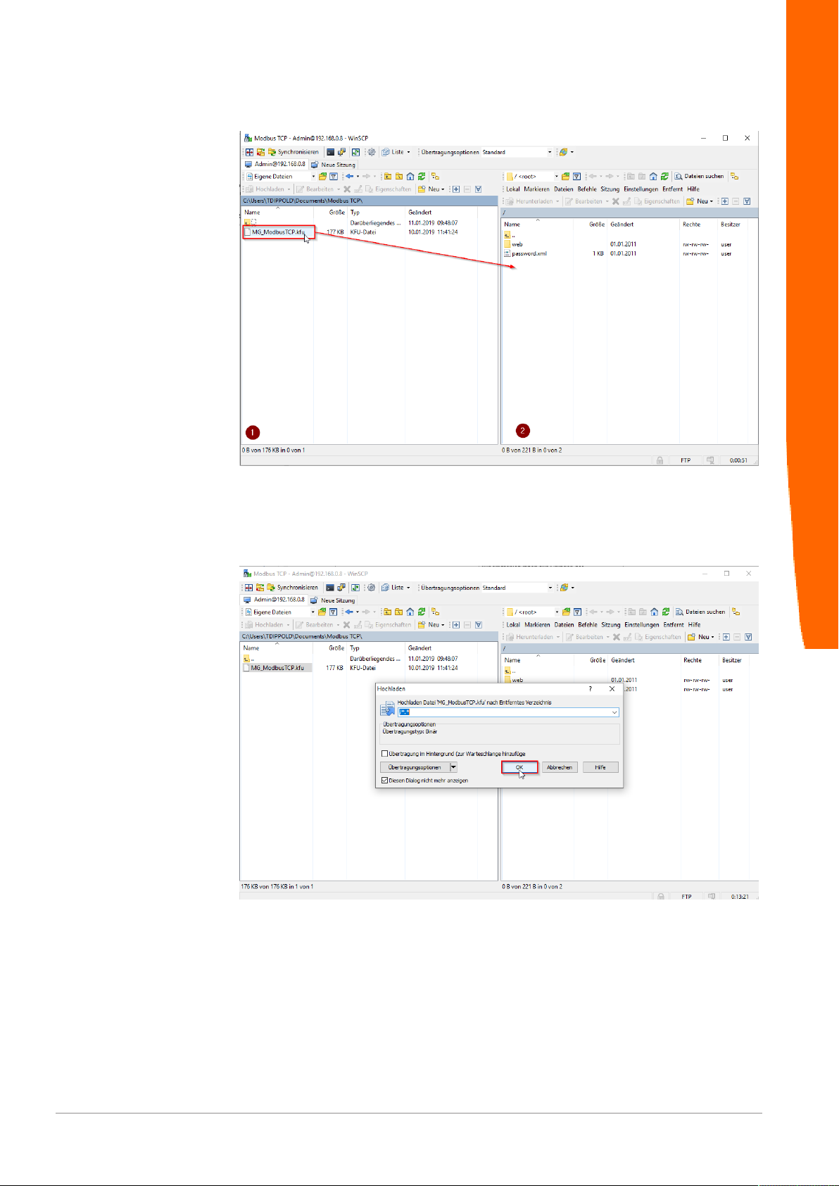
◦ Select in the kfu file from your local resources (window 1).
◦ Drag and drop the kfu file into the root directory of your gateway
component (window 2).
Integrated servers
The following window opens:
◦ Click on ok.
Gateway component ModbusTCP
26 / 30

The update file will now be copied.
After successful copying, the file appears in the root directory of the
gateway component..
Integrated servers
◦ Restart the gateway component.
Gateway component ModbusTCP 27 / 30
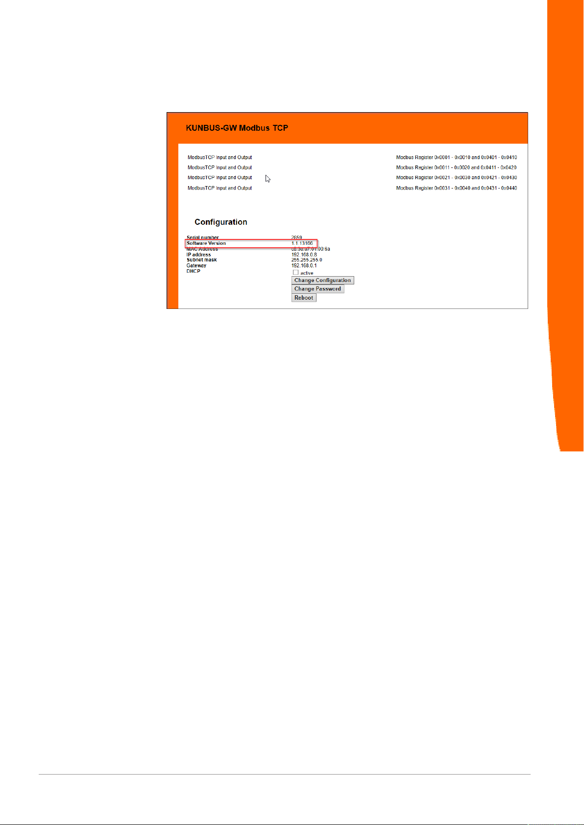
◦ Log on to the web server.
Here you can check whether the software version has changed.
Integrated servers
Gateway component ModbusTCP
28 / 30

7 Technical Data
7.1 Technical Data
Dimensions
Width 22.5 mm
Height 96 mm
Depth 110.4 mm
Weight 90 g
Electrical data
Power supply 24 V DC
Power consumption during operation
(cyclical data exchange)
Status display LED
Environmental conditions
Ambient temperature 0 – 60 °C
Storage temperature - 25 – 60 °C
Humidity 93% (at 40 °C)
Condensing Not allowed
Protection class
Control cabinet
Housing
Terminal area
100mA
IP54
IP20
IP20
Technical Data
Assembly data
DIN rail 35 x 7.5 mm
Height 96 mm
Depth 110.4 mm
Gateway component ModbusTCP 29 / 30
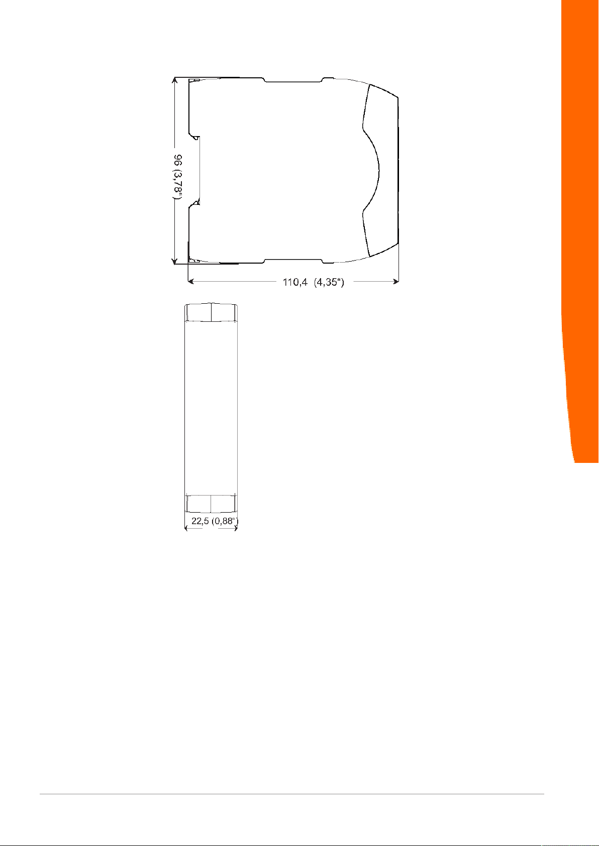
Illustration7: Side dimensions
Technical Data
Gateway component ModbusTCP
Illustration8: Front dimensions
30 / 30
 Loading...